WO2012105019A1 - 車両および車両の制御方法 - Google Patents
車両および車両の制御方法 Download PDFInfo
- Publication number
- WO2012105019A1 WO2012105019A1 PCT/JP2011/052224 JP2011052224W WO2012105019A1 WO 2012105019 A1 WO2012105019 A1 WO 2012105019A1 JP 2011052224 W JP2011052224 W JP 2011052224W WO 2012105019 A1 WO2012105019 A1 WO 2012105019A1
- Authority
- WO
- WIPO (PCT)
- Prior art keywords
- vehicle
- output shaft
- electric motor
- internal combustion
- switch
- Prior art date
Links
Images


Classifications
-
- B—PERFORMING OPERATIONS; TRANSPORTING
- B60—VEHICLES IN GENERAL
- B60K—ARRANGEMENT OR MOUNTING OF PROPULSION UNITS OR OF TRANSMISSIONS IN VEHICLES; ARRANGEMENT OR MOUNTING OF PLURAL DIVERSE PRIME-MOVERS IN VEHICLES; AUXILIARY DRIVES FOR VEHICLES; INSTRUMENTATION OR DASHBOARDS FOR VEHICLES; ARRANGEMENTS IN CONNECTION WITH COOLING, AIR INTAKE, GAS EXHAUST OR FUEL SUPPLY OF PROPULSION UNITS IN VEHICLES
- B60K6/00—Arrangement or mounting of plural diverse prime-movers for mutual or common propulsion, e.g. hybrid propulsion systems comprising electric motors and internal combustion engines ; Control systems therefor, i.e. systems controlling two or more prime movers, or controlling one of these prime movers and any of the transmission, drive or drive units Informative references: mechanical gearings with secondary electric drive F16H3/72; arrangements for handling mechanical energy structurally associated with the dynamo-electric machine H02K7/00; machines comprising structurally interrelated motor and generator parts H02K51/00; dynamo-electric machines not otherwise provided for in H02K see H02K99/00
- B60K6/20—Arrangement or mounting of plural diverse prime-movers for mutual or common propulsion, e.g. hybrid propulsion systems comprising electric motors and internal combustion engines ; Control systems therefor, i.e. systems controlling two or more prime movers, or controlling one of these prime movers and any of the transmission, drive or drive units Informative references: mechanical gearings with secondary electric drive F16H3/72; arrangements for handling mechanical energy structurally associated with the dynamo-electric machine H02K7/00; machines comprising structurally interrelated motor and generator parts H02K51/00; dynamo-electric machines not otherwise provided for in H02K see H02K99/00 the prime-movers consisting of electric motors and internal combustion engines, e.g. HEVs
- B60K6/42—Arrangement or mounting of plural diverse prime-movers for mutual or common propulsion, e.g. hybrid propulsion systems comprising electric motors and internal combustion engines ; Control systems therefor, i.e. systems controlling two or more prime movers, or controlling one of these prime movers and any of the transmission, drive or drive units Informative references: mechanical gearings with secondary electric drive F16H3/72; arrangements for handling mechanical energy structurally associated with the dynamo-electric machine H02K7/00; machines comprising structurally interrelated motor and generator parts H02K51/00; dynamo-electric machines not otherwise provided for in H02K see H02K99/00 the prime-movers consisting of electric motors and internal combustion engines, e.g. HEVs characterised by the architecture of the hybrid electric vehicle
- B60K6/44—Series-parallel type
- B60K6/445—Differential gearing distribution type
-
- B—PERFORMING OPERATIONS; TRANSPORTING
- B60—VEHICLES IN GENERAL
- B60W—CONJOINT CONTROL OF VEHICLE SUB-UNITS OF DIFFERENT TYPE OR DIFFERENT FUNCTION; CONTROL SYSTEMS SPECIALLY ADAPTED FOR HYBRID VEHICLES; ROAD VEHICLE DRIVE CONTROL SYSTEMS FOR PURPOSES NOT RELATED TO THE CONTROL OF A PARTICULAR SUB-UNIT
- B60W10/00—Conjoint control of vehicle sub-units of different type or different function
- B60W10/04—Conjoint control of vehicle sub-units of different type or different function including control of propulsion units
- B60W10/06—Conjoint control of vehicle sub-units of different type or different function including control of propulsion units including control of combustion engines
-
- B—PERFORMING OPERATIONS; TRANSPORTING
- B60—VEHICLES IN GENERAL
- B60W—CONJOINT CONTROL OF VEHICLE SUB-UNITS OF DIFFERENT TYPE OR DIFFERENT FUNCTION; CONTROL SYSTEMS SPECIALLY ADAPTED FOR HYBRID VEHICLES; ROAD VEHICLE DRIVE CONTROL SYSTEMS FOR PURPOSES NOT RELATED TO THE CONTROL OF A PARTICULAR SUB-UNIT
- B60W10/00—Conjoint control of vehicle sub-units of different type or different function
- B60W10/04—Conjoint control of vehicle sub-units of different type or different function including control of propulsion units
- B60W10/08—Conjoint control of vehicle sub-units of different type or different function including control of propulsion units including control of electric propulsion units, e.g. motors or generators
-
- B—PERFORMING OPERATIONS; TRANSPORTING
- B60—VEHICLES IN GENERAL
- B60W—CONJOINT CONTROL OF VEHICLE SUB-UNITS OF DIFFERENT TYPE OR DIFFERENT FUNCTION; CONTROL SYSTEMS SPECIALLY ADAPTED FOR HYBRID VEHICLES; ROAD VEHICLE DRIVE CONTROL SYSTEMS FOR PURPOSES NOT RELATED TO THE CONTROL OF A PARTICULAR SUB-UNIT
- B60W20/00—Control systems specially adapted for hybrid vehicles
-
- B—PERFORMING OPERATIONS; TRANSPORTING
- B60—VEHICLES IN GENERAL
- B60W—CONJOINT CONTROL OF VEHICLE SUB-UNITS OF DIFFERENT TYPE OR DIFFERENT FUNCTION; CONTROL SYSTEMS SPECIALLY ADAPTED FOR HYBRID VEHICLES; ROAD VEHICLE DRIVE CONTROL SYSTEMS FOR PURPOSES NOT RELATED TO THE CONTROL OF A PARTICULAR SUB-UNIT
- B60W2710/00—Output or target parameters relating to a particular sub-units
- B60W2710/06—Combustion engines, Gas turbines
- B60W2710/0644—Engine speed
-
- Y—GENERAL TAGGING OF NEW TECHNOLOGICAL DEVELOPMENTS; GENERAL TAGGING OF CROSS-SECTIONAL TECHNOLOGIES SPANNING OVER SEVERAL SECTIONS OF THE IPC; TECHNICAL SUBJECTS COVERED BY FORMER USPC CROSS-REFERENCE ART COLLECTIONS [XRACs] AND DIGESTS
- Y02—TECHNOLOGIES OR APPLICATIONS FOR MITIGATION OR ADAPTATION AGAINST CLIMATE CHANGE
- Y02T—CLIMATE CHANGE MITIGATION TECHNOLOGIES RELATED TO TRANSPORTATION
- Y02T10/00—Road transport of goods or passengers
- Y02T10/60—Other road transportation technologies with climate change mitigation effect
- Y02T10/62—Hybrid vehicles
-
- Y—GENERAL TAGGING OF NEW TECHNOLOGICAL DEVELOPMENTS; GENERAL TAGGING OF CROSS-SECTIONAL TECHNOLOGIES SPANNING OVER SEVERAL SECTIONS OF THE IPC; TECHNICAL SUBJECTS COVERED BY FORMER USPC CROSS-REFERENCE ART COLLECTIONS [XRACs] AND DIGESTS
- Y10—TECHNICAL SUBJECTS COVERED BY FORMER USPC
- Y10S—TECHNICAL SUBJECTS COVERED BY FORMER USPC CROSS-REFERENCE ART COLLECTIONS [XRACs] AND DIGESTS
- Y10S903/00—Hybrid electric vehicles, HEVS
- Y10S903/902—Prime movers comprising electrical and internal combustion motors
- Y10S903/903—Prime movers comprising electrical and internal combustion motors having energy storing means, e.g. battery, capacitor
- Y10S903/93—Conjoint control of different elements
Definitions
- the present invention relates to a vehicle and a vehicle control method, and more particularly to a technique for starting an internal combustion engine mounted on a vehicle.
- Patent Document 1 Japanese Patent Application Laid-Open No. 2007-23919
- the brake pedal is depressed when the push switch is pressed.
- a technique for restarting the engine even if it is not disclosed is disclosed.
- a hybrid vehicle equipped with a motor generator and an engine has attracted attention as one of countermeasures for environmental problems.
- a hybrid vehicle for example, a vehicle in which elements of a drive wheel, an engine, and a motor generator are mechanically connected is known.
- the output shaft of the motor generator may be negatively rotated even when the engine is stopped.
- the motor generator when the motor generator is driven to crank the engine, the motor generator can generate power.
- the power generation at this time is not intended. Therefore, electric power can be generated more than necessary.
- the purpose of the present invention is to limit the power generated.
- the vehicle includes a switch that is operated by a driver, an internal combustion engine that is started when the switch is operated, and an electric motor that is coupled to an output shaft of the internal combustion engine.
- the electric motor increases the output shaft rotation speed of the internal combustion engine with lower torque as the output shaft rotation speed of the electric motor is higher.
- a control method for a vehicle equipped with a switch operated by a driver, an internal combustion engine started by operating the switch, and an electric motor connected to an output shaft of the internal combustion engine is provided as a switch.
- the vehicle includes a switch operated by the driver, an internal combustion engine that starts when the switch is operated, and an electric motor coupled to the output shaft of the internal combustion engine.
- the electric motor increases the output shaft rotation speed of the internal combustion engine at a lower speed as the output shaft rotation speed of the electric motor is higher.
- a control method for a vehicle on which a switch operated by a driver, an internal combustion engine that starts when the switch is operated, and an electric motor that is coupled to an output shaft of the internal combustion engine are mounted.
- the electric motor increases the output shaft rotational speed of the internal combustion engine with a lower torque as the output shaft rotational speed of the electric motor increases.
- the output shaft rotation speed of the internal combustion engine is increased at a lower change speed (change rate) as the output shaft rotation speed of the electric motor is higher, the torque of the electric motor is reduced to reduce the change speed. Therefore, in any case, the torque is reduced as the output shaft rotational speed of the electric motor is higher. Therefore, when the output shaft of the electric motor is rotating negatively, the electric power generated by the electric motor is limited.
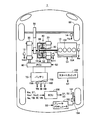
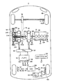
- FIG. 1 is an overall block diagram of a vehicle. It is a figure (the 1) which shows the alignment chart of a power split device. It is a functional block diagram of ECU. It is a figure which shows the flowchart of the process which ECU performs. It is a whole block diagram of vehicles of other embodiments. It is a figure which shows the operation
- FIG. 4 is a diagram (No. 4) illustrating a nomographic chart of the power split device; It is a figure (the 5) which shows an alignment chart of a power split device. It is a figure (the 6) which shows an alignment chart of a power split device.
- the vehicle 1 includes an engine 10, a drive shaft 16, a first motor generator (hereinafter referred to as a first MG) 20, a second motor generator (hereinafter referred to as a second MG) 30, and a power split device 40. , A reduction gear 58, a PCU (Power Control Unit) 60, a battery 70, a drive wheel 80, a start switch 150, a braking device 151, and an ECU (Electronic Control Unit) 200.
- the vehicle 1 travels by driving force output from at least one of the engine 10 and the second MG 30.
- the power generated by the engine 10 is divided into two paths by the power split device 40.
- One of the two routes is a route transmitted to the drive wheel 80 via the speed reducer 58, and the other route is a route transmitted to the first MG 20.
- the first MG 20 and the second MG 30 are, for example, three-phase AC rotating electric machines.
- First MG 20 and second MG 30 are driven by PCU 60.
- the first MG 20 has a function as a generator that generates power using the power of the engine 10 divided by the power split device 40 and charges the battery 70 via the PCU 60. Further, first MG 20 receives electric power from battery 70 and rotates a crankshaft that is an output shaft of engine 10. Thus, the first MG 20 has a function as a starter for starting the engine 10.
- the second MG 30 has a function as a driving motor that applies driving force to the driving wheels 80 using at least one of the electric power stored in the battery 70 and the electric power generated by the first MG 20. Second MG 30 also has a function as a generator for charging battery 70 via PCU 60 using electric power generated by regenerative braking.
- the engine 10 is an internal combustion engine such as a gasoline engine or a diesel engine.
- the engine 10 includes a plurality of cylinders 102 and a fuel injection device 104 that supplies fuel to each of the plurality of cylinders 102. Based on the control signal S1 from the ECU 200, the fuel injection device 104 injects an appropriate amount of fuel to each cylinder at an appropriate time, or stops fuel injection to each cylinder.
- the engine 10 is provided with an engine rotation speed sensor 11 for detecting the rotation speed of the crankshaft of the engine 10 (hereinafter referred to as engine rotation speed) Ne.
- the engine rotation speed sensor 11 transmits a signal indicating the detected engine rotation speed Ne to the ECU 200.
- the power split device 40 mechanically connects each of the three elements of the drive shaft 16 for rotating the drive wheel 80, the output shaft of the engine 10, and the rotation shaft (output shaft) of the first MG 20.
- the power split device 40 enables transmission of power between the other two elements by using any one of the three elements described above as a reaction force element.
- the rotation shaft (output shaft) of second MG 30 is connected to drive shaft 16.
- the power split device 40 is a planetary gear mechanism including a sun gear 50, a pinion gear 52, a carrier 54, and a ring gear 56.
- Pinion gear 52 meshes with each of sun gear 50 and ring gear 56.
- the carrier 54 supports the pinion gear 52 so as to be capable of rotating, and is connected to the crankshaft of the engine 10.
- Sun gear 50 is coupled to the rotation shaft of first MG 20.
- Ring gear 56 is coupled to the rotation shaft of second MG 30 and reduction gear 58 via drive shaft 16.
- first MG 20 and second MG 30 are connected by power split device 40, rotation speed Nm1 of first MG 20, engine rotation speed Ne, and rotation speed Nm2 of second MG 30 are on the collinear diagram of FIG.
- the rotational speeds Nm1, Ne, and Nm2 of each element change so as to maintain the relationship connected by one straight line.
- the left vertical axis of the three vertical axes in the nomograph shows the rotational speed of the sun gear 50, that is, the rotational speed Nm1 of the first MG 20.
- the vertical axis at the center of the alignment chart shown in FIG. 2 indicates the rotational speed of the carrier 54, that is, the engine rotational speed Ne.
- the vertical axis on the right side of the alignment chart shown in FIG. 2 indicates the rotational speed of the ring gear 56, that is, the rotational speed Nm2 of the second MG 30.
- shaft of the alignment chart of FIG. 2 shows a normal rotation direction, and the direction opposite to the arrow direction shows a negative rotation direction.
- the vehicle 1 has a rotation speed Nm1 of the first MG 20 of Nm1 (0), an engine rotation speed Ne of Ne (0), and a rotation of the second MG 30. Assume that the speed Nm2 is Nm2 (0).
- Power split device 40 rotates the rotating shaft of first MG 20 even when the vehicle travels and engine 10 stops.
- the engine rotational speed Ne is reduced to zero.
- the rotation speed Nm1 of the first MG 20 increases in the negative rotation direction from Nm1 (0) to Nm1 (1). Therefore, the higher the vehicle speed, the higher the rotational speed Nm1 of the first MG 20 when the engine rotational speed Ne becomes zero (when the rotation of the engine 10 stops).
- the first MG 20 In order to increase the rotation speed of the first MG 20 from Nm1 (1) to Nm1 (0), when a torque in the positive rotation direction opposite to the rotation direction (negative rotation direction) of the first MG 20 is generated, the first MG 20 moves in the negative rotation direction. Since it is rotating, the first MG 20 generates power. In the present embodiment, as will be described later, the power generated by first MG 20 when cranking engine 10 is limited.
- the speed reducer 58 transmits the power from the power split device 40 and the second MG 30 to the drive wheels 80. Reducer 58 transmits the reaction force from the road surface received by drive wheels 80 to power split device 40 and second MG 30.
- PCU 60 converts the DC power stored in battery 70 into AC power for driving first MG 20 and second MG 30.
- PCU 60 includes a converter and an inverter (both not shown) controlled based on control signal S2 from ECU 200.
- the converter boosts the voltage of the DC power received from battery 70 and outputs it to the inverter.
- the inverter converts the DC power output from the converter into AC power and outputs the AC power to first MG 20 and / or second MG 30.
- first MG 20 and / or second MG 30 are driven using the electric power stored in battery 70.
- the inverter converts AC power generated by the first MG 20 and / or the second MG 30 into DC power and outputs the DC power to the converter.
- the converter steps down the voltage of the DC power output from the inverter and outputs the voltage to battery 70. Thereby, battery 70 is charged using the electric power generated by first MG 20 and / or second MG 30.
- the converter may be omitted.
- the battery 70 is a power storage device and a rechargeable DC power source.
- a secondary battery such as nickel metal hydride or lithium ion is used.
- the voltage of the battery 70 is about 200V, for example.
- Battery 70 may be charged using electric power supplied from an external power source (not shown) in addition to being charged using electric power generated by first MG 20 and / or second MG 30 as described above.
- the battery 70 is not limited to a secondary battery, but may be a battery capable of generating a DC voltage, such as a capacitor, a solar battery, or a fuel battery.
- the battery 70 includes a battery temperature sensor 156 for detecting the battery temperature TB of the battery 70, a current sensor 158 for detecting the current IB of the battery 70, and a voltage sensor 160 for detecting the voltage VB of the battery 70. And are provided.
- the battery temperature sensor 156 transmits a signal indicating the battery temperature TB to the ECU 200.
- Current sensor 158 transmits a signal indicating current IB to ECU 200.
- Voltage sensor 160 transmits a signal indicating voltage VB to ECU 200.
- the start switch 150 is, for example, a push-type switch.
- the start switch 150 may be configured to insert a key into a key cylinder and rotate it to a predetermined position.
- Start switch 150 is connected to ECU 200.
- the start switch 150 transmits a signal ST to the ECU 200.
- the ECU200 judges that it received the start instruction, for example, when signal ST is received when the system of vehicle 1 is a stop state, and makes the system of vehicle 1 shift from a stop state to a start state. Further, when the signal ST is received when the system of the vehicle 1 is in the activated state, the ECU 200 determines that the stop instruction has been received, and shifts the system of the vehicle 1 from the activated state to the stopped state.
- the operation of the start switch 150 by the driver when the system of the vehicle 1 is in the activated state is referred to as an IG off operation, and the driver operates the start switch 150 when the system of the vehicle 1 is in the stopped state.
- the operation is called IG on operation.
- the vehicle 1 becomes operable by supplying power to a plurality of devices necessary for the vehicle 1 to travel.
- the system of the vehicle 1 shifts to the stop state, the supply of power to a part of the plurality of devices necessary for the vehicle 1 to travel is stopped, so that the operation stop state Become.
- the first resolver 12 detects the rotational speed Nm1 of the first MG 20.
- the first resolver 12 transmits a signal indicating the detected rotation speed Nm1 to the ECU 200.
- the second resolver 13 detects the rotational speed Nm2 of the second MG 30.
- the second resolver 13 transmits a signal indicating the detected rotation speed Nm2 to the ECU 200.
- the wheel speed sensor 14 detects the rotational speed Nw of the drive wheel 80.
- the wheel speed sensor 14 transmits a signal indicating the detected rotation speed Nw to the ECU 200.
- ECU 200 calculates vehicle speed V based on the received rotational speed Nw.
- ECU 200 may calculate vehicle speed V based on rotation speed Nm2 of second MG 30 instead of rotation speed Nw.
- the braking device 151 includes a brake actuator 152 and a disc brake 154.
- the disc brake 154 includes a brake disc that rotates integrally with the wheel, and a brake caliper that restricts rotation of the brake disc using hydraulic pressure.
- the brake caliper includes a brake pad provided so as to sandwich the brake disc in a direction parallel to the rotation shaft, and a wheel cylinder for transmitting hydraulic pressure to the brake pad.
- the brake actuator 152 Based on the control signal S3 received from the ECU 200, the brake actuator 152 adjusts the hydraulic pressure generated when the driver depresses the brake pedal and the hydraulic pressure generated using a pump, a solenoid valve, and the like, and supplies the hydraulic pressure to the wheel cylinder. Adjust the hydraulic pressure.
- the braking device 151 is illustrated only on the right side of the rear wheel, but the braking device 151 is provided for each wheel.
- the ECU 200 generates a control signal S1 for controlling the engine 10 and outputs the generated control signal S1 to the engine 10.
- ECU 200 also generates a control signal S2 for controlling PCU 60 and outputs the generated control signal S2 to PCU 60.
- ECU 200 generates a control signal S3 for controlling brake actuator 152, and outputs the generated control signal S3 to brake actuator 152.
- the ECU 200 controls the entire hybrid system, that is, the charging / discharging state of the battery 70 and the operating states of the engine 10, the first MG 20 and the second MG 30 so that the vehicle 1 can operate most efficiently by controlling the engine 10, the PCU 60, and the like. .
- ECU 200 calculates the required driving force corresponding to the amount of depression of an accelerator pedal (not shown) provided in the driver's seat. ECU 200 determines the torque of first MG 20 and second MG 30 according to the calculated required driving force. And the output of the engine 10 is controlled.
- the vehicle 1 when the engine 10 is inefficient at the time of starting or running at a low speed, the vehicle 1 travels only by the second MG 30. Further, during normal travel, for example, the power split device 40 divides the power of the engine 10 into two paths of power.
- the drive wheel 80 is directly driven by one power.
- the first MG 20 is driven with the other power to generate power.
- ECU 200 drives second MG 30 using the generated electric power. In this way, driving of the driving wheel 80 is performed by driving the second MG 30.
- the second MG 30 driven by the rotation of the drive wheel 80 functions as a generator to perform regenerative braking.
- the electric power recovered by regenerative braking is stored in the battery 70.
- ECU 200 increases the output of engine 10 to increase the first MG 20 when the remaining capacity of the power storage device (described in the following description as SOC (State of Charge)) decreases and charging is particularly necessary. Increase the amount of power generated by Thereby, the SOC of the battery 70 is increased.
- the ECU 200 may perform control to increase the driving force from the engine 10 as necessary even during low-speed traveling. For example, the battery 70 needs to be charged as described above, an auxiliary machine such as an air conditioner is driven, or the temperature of the cooling water of the engine 10 is raised to a predetermined temperature.
- the ECU 200 determines the input power allowed when the battery 70 is charged based on the battery temperature TB and the current SOC (in the following description, “charging power upper limit value”). Output power (to be described as “discharge power upper limit value Wout” in the following description). For example, when the current SOC decreases, discharge power upper limit Wout is set to be gradually lower. On the other hand, when the current SOC increases, charging power upper limit value Win is set to gradually decrease.
- the secondary battery used as the battery 70 has a temperature dependency in which the internal resistance increases at a low temperature. Further, at a high temperature, it is necessary to prevent the temperature from excessively rising due to further heat generation. For this reason, it is preferable to reduce each of the discharge power upper limit value Wout and the charge power upper limit value Win when the battery temperature TB is low and high. ECU 200 sets charge power upper limit value Win and discharge power upper limit value Wout by using, for example, a map or the like according to battery temperature TB and the current SOC.
- the torque of first MG 20 is limited so that the power generated by first MG 20 is smaller than charging power upper limit Win. Is done.
- FIG. 3 shows a functional block diagram of ECU 200 mounted on vehicle 1 according to the present embodiment.
- ECU 200 includes a determination unit 202 and a first MG control unit 204.
- the determination unit 202 determines whether or not the IG on operation has been performed.
- the determination unit 202 determines that the IG ON operation has been performed when the signal ST is received from the start switch 150 when the system of the vehicle 1 is in a stopped state, for example. Note that the determination unit 202 may turn on the IG ON determination flag when, for example, an IG ON operation is performed.
- the determination unit 202 determines whether or not the vehicle 1 is traveling. The determination unit 202 determines that the vehicle 1 is traveling when the vehicle speed V is higher than the predetermined vehicle speed V (0). Note that the determination unit 202 may turn on the travel determination flag when it is determined that the vehicle 1 is traveling.
- the first MG control unit 204 When it is determined by the determination unit 202 that the IG ON operation has been performed, that is, when the start switch 150 is operated by the driver, the first MG control unit 204 has a lower torque as the rotational speed Nm1 of the rotation shaft of the first MG 20 is higher.
- the first MG 20 is controlled so as to increase the engine rotational speed Ne.
- the first MG 20 increases the engine rotation speed Ne at a lower speed as the rotation speed Nm1 of the rotation shaft of the first MG 20 is higher. More specifically, the first MG 20 is controlled so that lower torque is generated in the forward rotation direction as the vehicle speed is higher. As described above, the torque of first MG 20 is limited so that the power generated by first MG 20 is smaller than charging power upper limit Win.
- Tm1 (v0) be the torque of the first MG 20 when cranking the engine 10 in a state where the vehicle speed is zero.
- Tm1 (v0) the torque of the first MG 20 when cranking the engine 10 in a state where the vehicle speed is zero.
- the torque of the first MG 20 is also lowered by Tm1 (v0). The torque of the first MG 20 is reduced until the power generated by the first MG 20 becomes smaller than the charging power upper limit Win.
- the electric power generated by first MG 20 may be calculated using a known technique such as calculating from a map having torque and rotational speed as parameters, and therefore detailed description of the calculation method will not be repeated here. .
- the method for controlling the torque of the first MG 20 may similarly use a known technique.
- both the determination unit 202 and the first MG control unit 204 are described as functioning as software realized by the CPU of the ECU 200 executing a program stored in the memory. It may be realized by hardware. Such a program is recorded on a storage medium and mounted on the vehicle.
- step (hereinafter, step is referred to as S) 100 ECU 200 determines whether or not an IG on operation has been performed. If the IG-on operation has been performed (YES in S100), ECU 200 determines in S102 whether vehicle 1 is traveling.
- ECU 200 causes first MG 20 to increase engine rotational speed Ne with a lower torque as rotational speed Nm1 of the rotating shaft of first MG 20 is higher. Control.
- the electric power generated by the first MG 20 is limited as the engine rotational speed Ne is increased. Therefore, it is possible to protect the electric device such as the first MG 20 from heat generation or to protect the battery 70 from overcharging.
- the ECU 200 controls the engine 10 so as to start fuel injection and ignition. That is, the engine 10 is started.
- the first MG 20 increases the engine rotation speed with a lower torque as the rotation speed Nm1 of the first MG 20 is higher. Therefore, when the first MG 20 is rotating negatively when starting the engine 10, the electric power generated by the first MG 20 is limited.
- planetary gear mechanism including sun gear 310, pinion gear 312, carrier 314, and ring gear 316 is mounted on vehicle 1 of the present embodiment as power split device 300.
- Sun gear 310 is connected to the rotation shaft of second MG 30.
- Pinion gear 312 meshes with each of sun gear 310 and ring gear 316.
- the carrier 314 supports the pinion gear 312 so that it can rotate, and is connected to the speed reducer 58 via the drive shaft 18.
- FIG. 6 shows an operation table of the C1 clutch 321, the C2 clutch 322, and the C3 clutch 323.
- “1 motor” in FIG. 6 means a control mode in which only one motor generator runs as a drive source. “Two motors” means a control mode in which two motor generators are used as driving sources. “Series” means a control mode that gives the vehicle 1 a function as a series hybrid vehicle. “Series + Parallel” means a control mode that gives the vehicle 1 a function as a series hybrid vehicle and a function as a parallel hybrid vehicle. “X” means “engaged state”.
- the ring gear 316 is fixed to be non-rotatable when the C1 clutch 321 is engaged, the C2 clutch 322 is released, and the C3 clutch 323 is released. That is, as shown in the alignment chart of FIG. 7, the rotational speed of the ring gear 316 is zero. In this state, the vehicle 1 travels using only the second MG 30 as a drive source.
- the vehicle 1 When the C1 clutch 321 is engaged, the C2 clutch 322 is released, and the C3 clutch 323 is engaged, as shown in the collinear diagram of FIG. 8, the vehicle 1 generates the second MG 30 while generating power with the first MG 20. It can run as a drive source.
- the ring gear 316 is connected to the first MG 20 when the C1 clutch 321 is released, the C2 clutch 322 is engaged, and the C3 clutch 323 is released. As shown in the nomograph of FIG. 9, in this state, the vehicle 1 can travel using the first MG 20 and the second MG 30 as drive sources.
- Ring gear 316 is connected to first MG 20 and engine 10 when C1 clutch 321 is released, C2 clutch 322 is engaged, and C3 clutch 323 is engaged. As shown in the alignment chart of FIG. 10, in this state, the vehicle 1 can travel using the engine 10 and the second MG 30 as drive sources while generating power with the first MG 20.
- the left vertical axis among the three vertical axes represents the rotational speed of the sun gear 310, that is, the rotational speed Nm2 of the second MG 20.
- the central vertical axis indicates the rotational speed of the carrier 314, that is, the rotational speed Nout of the drive shaft 18.
- the right vertical axis indicates the rotational speed of the ring gear 316.
- the rotation speed of the ring gear 316 may be the same as the rotation speed Ne of the engine 10 or the rotation speed Nm1 of the first MG 20.
- the second MG 30 outputs torque in the negative rotation direction, as shown in FIG.
- the engine speed Ne can be increased from zero.
- the engine speed Ne can be increased in order to start the engine 10.
- the rotational speed Nm2 of the second MG 30 is higher as the rotational speed of the drive shaft 18, that is, the vehicle speed is higher.
- the second MG 30 is controlled to increase the engine rotational speed Ne with a lower torque as the vehicle speed is higher. That is, the second MG 30 increases the engine rotation speed Ne with a lower torque as the rotation speed Nm1 of the second MG 30 is higher. Thereby, the electric power generated by the second MG 30 is limited.
Abstract
Description
以下、前述した動力分割装置40とは異なる形態の動力分割装置300を用いた実施の形態について説明する。図5に示すように、本実施の形態の車両1には、動力分割装置300として、サンギヤ310と、ピニオンギヤ312と、キャリア314と、リングギヤ316とを含む遊星歯車機構が搭載される。
Claims (8)
- 運転者が操作するスイッチ(150)と、
前記スイッチ(150)が操作されることによって始動する内燃機関(10)と、
前記内燃機関(10)の出力軸に連結される電動モータ(20,30)とを備え、
前記電動モータ(20,30)は、前記スイッチ(150)が操作されると、前記電動モータ(20,30)の出力軸回転速度が高いほどより低いトルクで前記内燃機関(10)の出力軸回転速度を上昇させる、車両。 - 前記内燃機関(10)の出力軸と前記電動モータ(20,30)の出力軸とを連結する連結装置(40,300)をさらに備え、前記連結装置(40,300)は、前記車両が走行し、かつ前記内燃機関(10)が停止した状態において前記電動モータ(20,30)の出力軸を回転させる、請求項1に記載の車両。
- 前記連結装置(40,300)は、車速が高いほど前記電動モータ(20,30)の出力軸回転速度を高くし、
前記電動モータ(20,30)は、前記スイッチ(150)が操作されると、車速が高いほどより低いトルクで前記内燃機関(10)の出力軸回転速度を上昇させる、請求項2に記載の車両。 - 前記連結装置(40)は、サンギヤ(50)、キャリア(54)、およびリングギヤ(56)を含み、
前記サンギヤ(50)は前記電動モータ(20)の出力軸に連結され、
前記キャリア(54)は前記内燃機関(10)の出力軸に連結され、
前記リングギヤ(56)は車輪(80)に連結される、請求項3に記載の車両。 - 前記電動モータ(20,30)のトルクは、前記電動モータ(20,30)が発生する電力が予め定められた上限値よりも小さくなるように制限される、請求項1に記載の車両。
- 運転者が操作するスイッチ(150)と、前記スイッチ(150)が操作されることによって始動する内燃機関(10)と、前記内燃機関(10)の出力軸に連結される電動モータ(20,30)とが搭載された車両の制御方法であって、
前記スイッチ(150)が操作されたか否かを判断するステップと、
前記スイッチ(150)が操作されると、前記電動モータ(20,30)により、前記電動モータ(20,30)の出力軸回転速度が高いほどより低いトルクで前記内燃機関(10)の出力軸回転速度を上昇させるステップとを備える、車両の制御方法。 - 運転者が操作するスイッチ(150)と、
前記スイッチ(150)が操作されることによって始動する内燃機関(10)と、
前記内燃機関(10)の出力軸に連結される電動モータ(20,30)とを備え、
前記電動モータ(20,30)は、前記スイッチ(150)が操作されると、前記電動モータ(20,30)の出力軸回転速度が高いほどより低い速度で前記内燃機関(10)の出力軸回転速度を上昇させる、車両。 - 運転者が操作するスイッチ(150)と、前記スイッチ(150)が操作されることによって始動する内燃機関(10)と、前記内燃機関(10)の出力軸に連結される電動モータ(20,30)とが搭載された車両の制御方法であって、
前記スイッチ(150)が操作されたか否かを判断するステップと、
前記スイッチ(150)が操作されると、前記電動モータ(20,30)により、前記電動モータ(20,30)の出力軸回転速度が高いほどより低い速度で前記内燃機関(10)の出力軸回転速度を上昇させるステップとを備える、車両の制御方法。
Priority Applications (3)
| Application Number | Priority Date | Filing Date | Title |
|---|---|---|---|
| JP2011554005A JPWO2012105019A1 (ja) | 2011-02-03 | 2011-02-03 | 車両および車両の制御方法 |
| US13/518,959 US20130311015A1 (en) | 2011-02-03 | 2011-02-03 | Vehicle and control method for vehicle |
| PCT/JP2011/052224 WO2012105019A1 (ja) | 2011-02-03 | 2011-02-03 | 車両および車両の制御方法 |
Applications Claiming Priority (1)
| Application Number | Priority Date | Filing Date | Title |
|---|---|---|---|
| PCT/JP2011/052224 WO2012105019A1 (ja) | 2011-02-03 | 2011-02-03 | 車両および車両の制御方法 |
Publications (1)
| Publication Number | Publication Date |
|---|---|
| WO2012105019A1 true WO2012105019A1 (ja) | 2012-08-09 |
Family
ID=46602260
Family Applications (1)
| Application Number | Title | Priority Date | Filing Date |
|---|---|---|---|
| PCT/JP2011/052224 WO2012105019A1 (ja) | 2011-02-03 | 2011-02-03 | 車両および車両の制御方法 |
Country Status (3)
| Country | Link |
|---|---|
| US (1) | US20130311015A1 (ja) |
| JP (1) | JPWO2012105019A1 (ja) |
| WO (1) | WO2012105019A1 (ja) |
Families Citing this family (2)
| Publication number | Priority date | Publication date | Assignee | Title |
|---|---|---|---|---|
| CN103442926A (zh) * | 2011-03-24 | 2013-12-11 | 丰田自动车株式会社 | 车辆及车辆用控制方法 |
| JP7188274B2 (ja) * | 2019-05-14 | 2022-12-13 | トヨタ自動車株式会社 | ハイブリッド車両 |
Citations (1)
| Publication number | Priority date | Publication date | Assignee | Title |
|---|---|---|---|---|
| JP2010188800A (ja) * | 2009-02-17 | 2010-09-02 | Nissan Motor Co Ltd | ハイブリッド車両の制御装置 |
-
2011
- 2011-02-03 US US13/518,959 patent/US20130311015A1/en not_active Abandoned
- 2011-02-03 WO PCT/JP2011/052224 patent/WO2012105019A1/ja active Application Filing
- 2011-02-03 JP JP2011554005A patent/JPWO2012105019A1/ja active Pending
Patent Citations (1)
| Publication number | Priority date | Publication date | Assignee | Title |
|---|---|---|---|---|
| JP2010188800A (ja) * | 2009-02-17 | 2010-09-02 | Nissan Motor Co Ltd | ハイブリッド車両の制御装置 |
Also Published As
| Publication number | Publication date |
|---|---|
| US20130311015A1 (en) | 2013-11-21 |
| JPWO2012105019A1 (ja) | 2014-07-03 |
Similar Documents
| Publication | Publication Date | Title |
|---|---|---|
| US9796375B2 (en) | Control system for hybrid vehicle | |
| JP5725037B2 (ja) | 車両および車両用制御方法 | |
| JP5652479B2 (ja) | 車両および車両用制御方法 | |
| JP5648984B2 (ja) | ハイブリッド車両 | |
| JP5949731B2 (ja) | ハイブリッド車両 | |
| JP2020089180A (ja) | 電動車両およびその制御方法 | |
| JP5598555B2 (ja) | 車両および車両用制御方法 | |
| JP5729475B2 (ja) | 車両および車両の制御方法 | |
| JP2010058579A (ja) | ハイブリッド車両 | |
| JP5644868B2 (ja) | 車両および車両の制御方法 | |
| JP2013141858A (ja) | ハイブリッド車両の制御装置 | |
| JP5780314B2 (ja) | 車両の制御装置 | |
| JP2011097666A (ja) | 自動車およびその制御方法 | |
| JP5765419B2 (ja) | 車両および車両用制御方法 | |
| JP2012224215A (ja) | ハイブリッド車 | |
| JP5652546B2 (ja) | 車両および車両用制御方法 | |
| JP2012162097A (ja) | 車両 | |
| WO2012105019A1 (ja) | 車両および車両の制御方法 | |
| JP2012224304A (ja) | 車両の制振制御装置 | |
| JP5810580B2 (ja) | 車両および車両用制御方法 | |
| JP5981119B2 (ja) | 車両 | |
| JP2012236470A (ja) | 車両の制振制御装置 | |
| JP2013032096A (ja) | ハイブリッド車両 |
Legal Events
| Date | Code | Title | Description |
|---|---|---|---|
| WWE | Wipo information: entry into national phase |
Ref document number: 2011554005 Country of ref document: JP |
|
| WWE | Wipo information: entry into national phase |
Ref document number: 13518959 Country of ref document: US |
|
| 121 | Ep: the epo has been informed by wipo that ep was designated in this application |
Ref document number: 11857795 Country of ref document: EP Kind code of ref document: A1 |
|
| NENP | Non-entry into the national phase |
Ref country code: DE |
|
| 122 | Ep: pct application non-entry in european phase |
Ref document number: 11857795 Country of ref document: EP Kind code of ref document: A1 |