WO2013011939A1 - 電動モータ及びターボ圧縮機 - Google Patents
電動モータ及びターボ圧縮機 Download PDFInfo
- Publication number
- WO2013011939A1 WO2013011939A1 PCT/JP2012/067914 JP2012067914W WO2013011939A1 WO 2013011939 A1 WO2013011939 A1 WO 2013011939A1 JP 2012067914 W JP2012067914 W JP 2012067914W WO 2013011939 A1 WO2013011939 A1 WO 2013011939A1
- Authority
- WO
- WIPO (PCT)
- Prior art keywords
- electric motor
- refrigerant
- injection nozzle
- space
- rotor
- Prior art date
Links
Images


Classifications
-
- F—MECHANICAL ENGINEERING; LIGHTING; HEATING; WEAPONS; BLASTING
- F04—POSITIVE - DISPLACEMENT MACHINES FOR LIQUIDS; PUMPS FOR LIQUIDS OR ELASTIC FLUIDS
- F04D—NON-POSITIVE-DISPLACEMENT PUMPS
- F04D29/00—Details, component parts, or accessories
- F04D29/58—Cooling; Heating; Diminishing heat transfer
- F04D29/5806—Cooling the drive system
-
- H—ELECTRICITY
- H02—GENERATION; CONVERSION OR DISTRIBUTION OF ELECTRIC POWER
- H02K—DYNAMO-ELECTRIC MACHINES
- H02K9/00—Arrangements for cooling or ventilating
- H02K9/19—Arrangements for cooling or ventilating for machines with closed casing and closed-circuit cooling using a liquid cooling medium, e.g. oil
- H02K9/20—Arrangements for cooling or ventilating for machines with closed casing and closed-circuit cooling using a liquid cooling medium, e.g. oil wherein the cooling medium vaporises within the machine casing
-
- H—ELECTRICITY
- H02—GENERATION; CONVERSION OR DISTRIBUTION OF ELECTRIC POWER
- H02K—DYNAMO-ELECTRIC MACHINES
- H02K5/00—Casings; Enclosures; Supports
- H02K5/04—Casings or enclosures characterised by the shape, form or construction thereof
- H02K5/16—Means for supporting bearings, e.g. insulating supports or means for fitting bearings in the bearing-shields
- H02K5/173—Means for supporting bearings, e.g. insulating supports or means for fitting bearings in the bearing-shields using bearings with rolling contact, e.g. ball bearings
- H02K5/1732—Means for supporting bearings, e.g. insulating supports or means for fitting bearings in the bearing-shields using bearings with rolling contact, e.g. ball bearings radially supporting the rotary shaft at both ends of the rotor
Definitions
- the present invention relates to an electric motor including a rotor and a stator provided around the rotor, and cooling the stator with a liquid coolant, and a turbo compressor using the electric motor.
- Patent Document 1 discloses an electric motor that supplies liquid refrigerant into a rotating bottomed cylindrical rotor. In this electric motor, the rotor is cooled by the heat of vaporization of the liquid refrigerant.
- Patent Document 2 discloses an electric motor in which the refrigerant supply amount is controlled. In this electric motor, by controlling the refrigerant supply amount, poor cooling due to supercooling or mixing of liquid refrigerant into the lubricating oil is prevented.
- the rotor is cooled, but the stator is not sufficiently cooled.
- the liquid refrigerant that has not been vaporized by the rotor falls on the stator in the middle of falling into the drain, and the stator is only cooled by this liquid refrigerant.
- the coil end on the bottom side of the rotor is cooled only by heat conduction, and thus is not sufficiently cooled. For this reason, the possibility of burning of the electric motor could not be resolved.
- An object of the present invention is to provide an electric motor capable of sufficiently cooling a coil end of a stator coil.
- a first feature of the present invention is an electric motor, which is provided around a motor case, a rotor housed in the motor case and rotatable about a rotation shaft, and the rotor in the motor case.
- a stator that is formed by winding a stator coil around a stator core, and a first injection nozzle that is provided in the motor case and that injects a liquid coolant toward the inner peripheral surface of the motor case.
- the stator coil has a first coil end projecting from the stator core in the direction of the rotation axis, and the first injection nozzle repels the coolant on the inner peripheral surface to form a mist
- an electric motor characterized in that the electric motor is configured to be diffused in a shape and fall on the first coil end.
- the coolant is sprayed from the first injection nozzle toward the inner peripheral surface of the motor case, and the coolant is bounced off the inner peripheral surface and diffuses in a mist form.
- the diffused mist-like coolant falls on the first coil end and cools the coil end with the heat of vaporization. For this reason, rather than cooling the coil end by heat conduction, the first coil end can be sufficiently cooled, and the possibility of burning due to a temperature rise of the electric motor can be eliminated. As a result, the reliability of the electric motor is improved. Further, since the generated mist-like coolant falls on the first coil end at a low speed, damage to the insulating coating film of the stator coil can be prevented.
- a second feature of the present invention is a turbo compressor that drives an impeller by the electric motor of the first feature described above, wherein the interior of the motor case is located on one side of the rotor and the stator.
- the space is divided into a second space located on the other side of the rotor and the stator, the first coil end projects into the first space, and the first injection nozzle is the first injection nozzle.
- the electric motor Provided in the space, injecting the coolant into the first space, the electric motor further comprising a gas injection nozzle for injecting a high-pressure gas into the second space, the high-pressure gas,
- a turbo compressor characterized in that it is the gaseous refrigerant compressed by an impeller.
- FIG. 3 is a sectional view taken along line III-III in FIG. 2.
- FIG. 4 is a longitudinal sectional view taken along line IV-IV in FIG. 3. It is a top view of the injection nozzle of the said electric motor.
- FIG. 6 is a sectional view taken along line VI-VI in FIG. 5.
- FIG. 9 is a cross-sectional view taken along line IX-IX in FIG.
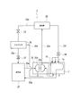
- the electric motor 1 is provided as a drive source for the turbo compressor 20 in the refrigeration cycle of the turbo chiller 2.
- the turbo refrigerator 2 is an apparatus for generating cooling water for air conditioning (coolant for air conditioning).
- the turbo refrigerator 2 includes a compressor 20, an evaporator 21, a condenser 22, and an economizer 26. These devices are connected by refrigerant pipes 25a to 25e for circulating a refrigerant (refrigerant: chlorofluorocarbon).
- the condenser 22 is connected to the compressor 20 via a flow path 25a, and is connected to an economizer 26 via a flow path 25b in which an expansion valve (pressure reducer [pressure reducer]) 23 is disposed.
- the condenser 22 is supplied with the gas refrigerant (refrigerant gas) compressed by the compressor 20 via the flow path 25a.
- the condenser 22 condenses the compressed gas refrigerant into a liquid refrigerant (a part remains as a gas refrigerant).
- the liquid refrigerant condensed in the condenser 22 (or refrigerant in a gas-liquid mixed state) is decompressed by the expansion valve 23 via the flow path 25b and then supplied to the economizer 26.
- the economizer 26 is connected to the evaporator 21 via a flow path 25c in which an expansion valve (decompressor) 27 is disposed, and is connected to the compressor 20 via a flow path 25d.
- the economizer 26 temporarily stores liquid refrigerant (partially gas refrigerant) decompressed by the expansion valve (pressure reducing valve) 23 on the flow path 25c.
- the gas-phase component [gas-phase component] (gas-refrigerant) of the refrigerant (gas-liquid mixed state) stored in the economizer 26 is supplied to the second compression stage [second compression stage] (first 2 impeller) 20b.
- liquid-phase component (liquid refrigerant) of the refrigerant (gas-liquid mixed state) stored in the economizer 26 is supplied to the evaporator 21 after being decompressed by the expansion valve 27 on the flow path 25c.
- the evaporator 21 is connected to a first compression stage (first impeller) 20a of the compressor 20 through a flow path 25e.
- the evaporator 21 evaporates the liquid refrigerant decompressed by the expansion valve 27 on the flow path 25c into a gas refrigerant.
- the gas refrigerant evaporated in the evaporator 21 is supplied to the first compression stage 20a of the compressor 20 through the flow path 21e.
- the compressor 20 is connected to the condenser 22 through a flow path 25a, and includes the first compression stage 20a and the second compression stage 20b described above.
- the compressor 20 compresses the gas refrigerant supplied through the flow path 25e by the first compression stage 20a and discharges it to the flow path 25d, and also supplies the gas refrigerant (first compression stage) through the flow path 25d.
- the gas refrigerant (including the gas refrigerant discharged from 20a) is compressed by the second compression stage 20b and discharged to the flow path 25a as a gas refrigerant.
- the gas refrigerant compressed by the compressor 20 is supplied to the condenser 22 via the flow path 25a.
- the cooling water for air conditioning is cooled by heat exchange with the refrigerant in the evaporator 21.
- the turbo chiller 2 of the present embodiment also includes a cooling system for the electric motor 1 using a refrigerant of the refrigeration cycle in addition to the above-described refrigeration cycle.
- the liquid refrigerant condensed in the condenser 22 (or the gas-liquid mixed state refrigerant) is supplied to the electric motor 1 through the flow path 25f.
- the supply amount of the liquid refrigerant to the electric motor 1 is controlled by a controller [regulator] 24 (flow control valve, orifice, etc.) on the flow path 25f.
- the liquid refrigerant supplied to the electric motor 1 cools the electric motor 1 and then returns to the evaporator 21 (refrigeration cycle).
- a part of the liquid refrigerant circulates around the stator 5 (see FIG. 4), and the remaining part is injected into the electric motor 1 from a first injection nozzle 7a described later.
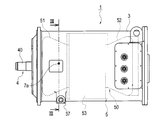
- the electric motor 1 will be described in detail. As shown in FIGS. 2 to 4, the electric motor 1 includes a cast motor case 3, a rotor 4 that can rotate around a rotating shaft 40, and a stator 5 provided around the rotor 4. .
- the motor case 3 includes a cylindrical peripheral wall 31, an end wall 32 that closes both ends of the peripheral wall 31, and a through-wall 33.
- An inner space [inner ⁇ chamber] 34 is formed inside the motor case 3 (the peripheral wall 31, the end wall 32, and the through wall 33).
- the stator 5 is fixed to the inner surface of the peripheral wall 31. From the center of the end wall 32, a support cylinder part [support cylinder] 32 a protrudes toward the internal space 34.
- a ball bearing [ball bearing] 60 ⁇ / b> A and a labyrinth seal 61 ⁇ / b> A are provided at the end of the bearing tube portion 32 a.
- a cylindrical hole 33a is provided in the center of the through wall 33.
- the cylindrical hole 33a is provided with a roller bearing [Bearing] 60B and a labyrinth seal 61B.
- the ball bearing 60A and the roller bearing 60B support the rotating shaft 40 so as to be rotatable.
- the internal space 34 is divided into a first space [first5chamber] 34A located on one side (left side in FIG. 4) by the rotor 4 and the stator 5, and a second space located on the other side (right side in FIG. 4). It is partitioned into a space [second chamber] 34B.
- the motor case 3 is provided with a first injection nozzle 7 a that injects the liquid refrigerant 8 toward the inner peripheral surface 30 in the first space 34 ⁇ / b> A.
- the first injection nozzle 7a is disposed along the radial direction of the motor case 3 toward the first coil end 51 protruding into the first space 34A.
- the first injection nozzle 7a will be described in detail later. In FIG. 4, since the first injection nozzle 7a is in front of the cross section, it is indicated by a dotted line.
- the stator 5 includes a cylindrical stator core 53 in which a plurality of electromagnetic steel plates are laminated, and a stator coil 50 wound around the teeth of the stator core 53.
- An insulating coating film such as varnish is formed on the surface of the stator coil 50.
- the stator coil 50 includes a first coil end protruding into the first space 34A along the axial direction of the rotating shaft 40 and a second coil protruding into the second space 34B along the axial direction of the rotating shaft 40. It has an end 52.
- the rotor 4 includes a rotating shaft 40, a cylindrical rotor core 41 in which a plurality of electromagnetic steel plates are laminated, and a rotor coil wound around the rotor core 41.
- the rotating shaft 40 passes through the rotor core 41 and is fixed to the rotor core 41.
- the rotor 4 is disposed inside the stator 5 and is rotatably supported by the end wall 32 and the through wall 33 via the rotary shaft 40 and the bearings 60A and 60B. That is, the stator 5 is provided around the rotor 4 in the motor case 3.
- the electric motor 1 is provided with a refrigerant flow path 35.
- the refrigerant flow path 35 circulates the liquid refrigerant 8 supplied from the outside inside the electric motor 1.
- the refrigerant flow path 35 is configured by a spiral groove formed on the inner peripheral surface 30 of the peripheral wall 31 so as to face the stator coil 53.
- the stator coil 53 is cooled by the liquid refrigerant 8 while the liquid refrigerant 8 flows through the refrigerant flow path 35.
- the first injection nozzle 7 a has a supply passage 70 extending in the axial direction inside thereof, and a discharge port 71 formed as a slit at the tip thereof. Yes.
- the supply path 70 supplies the liquid refrigerant 8 supplied from the outside of the motor case 3 to the discharge port 71.
- the supplied liquid refrigerant 8 is jetted from the discharge port 71 toward the inner peripheral surface 30 of the motor case 3.
- the opening direction of the discharge port 71 is set to a predetermined inclination angle A1 with respect to the axial direction of the first injection nozzle 7a.
- the liquid refrigerant 8 is injected toward the inner peripheral surface 30 of the motor case 3 at the inclination angle A1.
- the injected liquid refrigerant 8 maintains the inclination angle A1, and the thickness of the injection range is substantially constant.
- the discharge port 71 of the first injection nozzle 7 a is formed as a slit extending in the axial direction of the rotating shaft 40. Therefore, as shown in FIG. 5, the injected liquid refrigerant 8 diffuses in a fan shape along a plane parallel to the axial direction of the rotating shaft 40 [spread like a fan] (the fan-shaped central angle is a predetermined value). Diffusion angle A2).
- the mounting position of the first injection nozzle 7 a to the motor case 3, the inclination angle A 1, and the diffusion angle A 2 are mist-like (droplet-like) that has diffused the liquid refrigerant 8 in a wider range and bounced off the inner peripheral surface 30.
- the refrigerant 8 [refrigerant mists (refrigerant droplets) 8 splashed by the internal circumferential surface 30] is set according to the size of the electric motor 1 and the injection pressure of the liquid refrigerant 8 so that it falls on the entire first coil end 51. .
- the cooling operation will be described. First, cooling by the refrigerant passage 35 will be described with reference to FIG.
- the liquid refrigerant 8 supplied to the refrigerant passage 35 from the outside of the motor case 3 is vaporized by the heat of the stator coil 53 while flowing through the refrigerant passage 35, and the stator coil 53 is cooled by the heat of vaporization.
- the gas-liquid mixed refrigerant 8 that has passed through the refrigerant passage 35 is discharged into the second space 34B.
- the liquid refrigerant 8 discharged to the second space 34B falls on the second coil end 52, vaporizes with the heat of the second coil end 52, and cools the second coil end 52 with the heat of vaporization.
- the pressure in the second space 34B is increased by the gas refrigerant 8 generated by the vaporization of the liquid refrigerant 8, and the gas refrigerant 8 passes through the gap between the stator coil 53 and the rotor coil 41, and the first space has a low pressure.
- 34A Note that the liquid refrigerant (mist refrigerant) 8 discharged from the refrigerant passage 35 to the second space 34B and a part of the liquid refrigerant 8 stored in the lower portion of the second space 34B are also the stator coil 53 and the rotor coil. It moves to the first space 34 ⁇ / b> A through the gap with the space 41.
- the rotor 4 (and the stator 5) is cooled by the refrigerant 8 as the refrigerant 8 moves from the second space 34B to the first space 34A.
- the first injection nozzle 7a is provided to cool the first coil end 51 in the first space 34 ⁇ / b> A with the liquid refrigerant 8.
- the liquid refrigerant 8 is ejected from the discharge port 71 of the first injection nozzle 7a toward the inner peripheral surface 30 of the first space 34A, the liquid refrigerant 8 is bounced back on the inner peripheral surface 30 to form a mist (droplet shape). It becomes refrigerant 8 and diffuses over a wide area.
- the surface pattern of the mold of the casting motor case 3 is transferred onto the inner peripheral surface 30, and the inner peripheral surface 30 has fine asperities. For this reason, the inner peripheral surface 30 preferably rebounds the liquid refrigerant 8 as a mist (droplet-like) refrigerant 8.
- the diffused mist refrigerant 8 falls by gravity and falls onto the first coil end 51, vaporizes with the heat of the first coil end 51, and cools the first coil end 51 with the heat of vaporization.
- the first injection nozzle 7 a discharge port 71
- the liquid refrigerant 8 is injected from the first injection nozzle 7a (discharge port 71) in the rotation direction of the rotor 4 (counterclockwise in FIG. 2).
- a rotating flow that flows in the rotation direction is formed in the motor case 3 by the rotation of the rotor 4.
- the mist refrigerant 8 bounced off the inner peripheral surface 30 is carried to the entire first coil end 51 by the rotational flow, and the entire first coil end 51 (and the first coil end 51).
- the other part in one space 34A) can be cooled. Therefore, the cooling effect of the first coil end 51 is further improved.
- the liquid refrigerant 8 that has been ejected from the first injection nozzle 7a and has not been vaporized flows down through the groove 36 provided in the lower portion of the peripheral wall 31 together with the gas refrigerant 8 from the outlet [drain] 37 to the flow path 25g. (Refer to FIG. 1) and returned to the evaporator 21 (refrigeration cycle).
- the liquid refrigerant 8 is injected from the first injection nozzle 7 a toward the inner peripheral surface 30 to generate the mist refrigerant 8, and the first coil end 51 is moved by the mist refrigerant 8. Cool directly. For this reason, the 1st coil end 51 can fully be cooled rather than cooling a coil end mainly by heat conduction like the past. As a result, it is possible to prevent burnout and seizure due to the temperature rise of the electric motor 1.
- the mist refrigerant 8 reaches the first coil end 51 at a low speed. Therefore, damage to the insulating coating film of the first coil end 51 can be prevented. Furthermore, the mist refrigerant 8 can be diffused in a wide range by causing the liquid refrigerant 8 to rebound by the inner peripheral surface 30, and the entire first coil end 51 can be cooled by the mist refrigerant 8. Further, since the liquid refrigerant 8 is diffused and ejected in a fan shape from the discharge port 71 formed as a slit, the mist refrigerant 8 can be diffused over a wide range along the protruding direction of the first coil end 51. The coil end 51 can be effectively cooled.
- the first space in which the first injection nozzle 7 a for generating the mist refrigerant 8 falling on the first coil end 51 is provided is the output side of the driving force of the electric motor 1 (the rotation shaft 40 is It was a space 34A on the side protruding from the motor case 3 (left side in FIG. 4).
- the first injection nozzle 7a may be provided in the space 34B opposite to the output side of the electric motor 1 (that is, the space 34B is the first space).
- the 1st injection nozzle for producing the mist-like refrigerant which falls to the 1st coil end 51 may be provided in both spaces.
- the liquid refrigerant 8 from the refrigerant flow path 35 is discharged into the space (second space 34B) opposite to the output side of the electric motor 1.
- the refrigerant flow path 35 may be formed so that the liquid refrigerant 8 is discharged into the space 34 ⁇ / b> A on the output side of the electric motor 1.
- a mist refrigerant falling on the coil end 52 is generated in the opposite space 34B.
- a first injection nozzle is provided for the purpose (that is, the space 34B is the first space).
- the present embodiment has a configuration in which the cooling performance is further improved as compared with the first embodiment described above.
- a second injection nozzle 7b and a gas injection nozzle 9 are added to the configuration of the first embodiment in order to improve the cooling performance. Since the other configuration is the same as that of the first embodiment, the same or equivalent configuration is denoted by the same reference numeral, and redundant description thereof is omitted.
- the flow of the refrigerant 8 (gas refrigerant and mist refrigerant) from the second space 34B to the first space 34A is generated in the motor case 3, and the rotor 4 (and the stator 5) is caused by this flow.
- high pressure gas is injected into the second space 34B.
- FIG. 9 which is a sectional view taken along line IX-IX in FIG. 8, the gas injection nozzle 9 for injecting high-pressure gas into the second space 34B is provided in the motor case 3.
- the gas injection nozzle 9 since the gas injection nozzle 9 is behind the support cylinder portion 32a, it is indicated by a dotted line.
- the gas injection nozzle 9 is supplied with the high-pressure gas refrigerant 8 from the downstream side of the second compression stage (second impeller) 20b of the compressor 20.
- the pressure of the gas refrigerant 8 on the downstream side of the second compression stage (second impeller) 20b is high, which is suitable as a high-pressure gas.
- the high-pressure gas injected into the second space 34B is preferably the same refrigerant (high-pressure gas refrigerant) 8. Note that the high-pressure gas refrigerant 8 injected into the second space 34B has a high temperature, but the injection amount is small, and there is a decrease in temperature due to volume expansion in the second space 34B after injection. Does not affect the cooling performance.
- the pressure in the second space 34B increases, and the flow of the refrigerant 8 (gas refrigerant and mist refrigerant) from the second space 34B to the first space 34A is promoted. Is done.
- the amount of heat exchange between the refrigerant 8 and the rotor 4 (and the stator 5) is increased, and the cooling performance is improved.
- the configuration of the gas injection nozzle 9 is basically the same as that of the first injection nozzle 7a described above, and detailed description thereof will be omitted.
- the first injection nozzle 7a injects liquid refrigerant
- the gas injection nozzle 9 injects high-pressure gas (high-pressure gas refrigerant).
- the cross-sectional area of the internal flow path of the gas injection nozzle 9 and the shape of the discharge port are optimized for the high-pressure gas.
- the discharge port 71 of the first injection nozzle 7a is formed as a slit in order to diffuse and inject the liquid refrigerant.
- the discharge port of the gas injection nozzle 9 is not a slit but a round hole. It may be formed.
- the first embodiment of the first embodiment in order to further improve the cooling performance, in order to increase the amount of mist refrigerant 8 included in the flow of the refrigerant 8 from the second space 34B to the first space 34A, the first embodiment of the first embodiment.
- a second injection nozzle 7b having the same configuration as the one injection nozzle 7a is provided.
- the second injection nozzle 7b is provided on the opposite side of the gas injection nozzle 9 with respect to the rotation shaft 40 (the same side as the first injection nozzle 7a).
- the second injection nozzle 7b has the same configuration as the first injection nozzle 7a (see FIGS. 5 and 6), and injects the liquid refrigerant 8 toward the inner peripheral surface 30 of the second space 34B.
- the injected liquid refrigerant 8 bounces off the inner peripheral surface 30 to become a mist-like (droplet-like) refrigerant 8, and diffuses into the second space 34B.
- the diffused mist refrigerant 8 is moved from the second space 34B to the first space 34A by the flow of the refrigerant 8 promoted by the gas refrigerant 8 (high pressure gas) injected from the gas injection nozzle 9, and the rotor 4 (and Heat exchange with the stator 5) improves the cooling performance.
- the second injection nozzle 7b also injects the liquid refrigerant 8 in the rotation direction of the rotor 4 (counterclockwise in FIG. 9).
- the liquid refrigerant 8 is injected in the rotation direction of the rotor 4
- the generated mist refrigerant 8 is rotated. Therefore, it is stirred and easily included in the flow of the refrigerant 8 from the second space 34B to the first space 34A.
- the gas injection nozzle 9 also injects the gas refrigerant 8 (high pressure gas) in the rotation direction of the rotor 4.
- the rotational flow is promoted and the generated mist refrigerant 8 is further agitated.
- the mist refrigerant 8 is more easily contained by the flow of the refrigerant 8 from the second space 34B to the first space 34A.
- the mist-like refrigerant 8 is more uniformly diffused, the entire rotor 4 can be cooled.
- the refrigerant 8 discharged from the refrigerant flow path 35 is also diffused by the promotion of the rotational flow by the gas injection nozzle 9, and the entire second coil end 52 can be cooled more effectively.
- the gas injection nozzle 9 is outside the end edge of the second coil end 52 (projecting outside: It is preferable that the gas refrigerant 8 (high pressure gas) is injected into the right side in FIG.
- the gas injection nozzle 9 is configured to inject the gas refrigerant 8 (high-pressure gas) outside the edge of the second coil end 52, whereby the gas refrigerant 8 (injected from the gas injection nozzle 9) ( It is possible to prevent the insulating coating film of the second coil end 52 from being damaged by the high pressure gas.
- the gas injection nozzle 9 itself is disposed outside the end edge of the second coil end 52 (in the IX-IX cross section in FIG. 8).
- the first injection nozzle 7 a is arranged at substantially the center position of the protruding length of the first coil end 51 in order to efficiently sprinkle the generated mist refrigerant 8 on the first coil end 51.
- the second injection nozzle 7b diffuses the generated mist refrigerant 8 into the second space 34B in order to be included in the flow of the refrigerant 8 from the second space 34B to the first space 34A.
- the second injection nozzle 7b is provided at the same position as the gas injection nozzle 9 along the axial direction of the rotating shaft 40 (position on the IX-IX cross section in FIG. 8).
- mist refrigerant 8 generated by the second injection nozzle 7 b is rebounded by the inner peripheral surface 30 and sufficiently diffused into the second space 34 ⁇ / b> B, so that it is inside the edge of the second coil end 52. May be provided.
- the second coil end 52 may be cooled by sprinkling a part of the mist refrigerant 8 generated by the second injection nozzle 7 b on the second coil end 52.
- the gas refrigerant 8 as the high-pressure gas injected from the gas injection nozzle 9 is acquired from the downstream side of the second compression stage (second impeller) 20b of the compressor 20.
- the pressure may be acquired from the downstream side of the first compression stage (first impeller) 20a (that is, the upstream side of the second compression stage 20b).
- this embodiment is provided with all the structures of 1st Embodiment, and all the effects implement
- the piping for the gas injection nozzle 9 and the 2nd injection nozzle 7b increases, cooling performance (especially cooling of the rotor 5) can further be improved.
- the necessity of installing the injection nozzle 9 and the second injection nozzle 7 b may be examined.
Landscapes
- Engineering & Computer Science (AREA)
- Power Engineering (AREA)
- Physics & Mathematics (AREA)
- Thermal Sciences (AREA)
- Mechanical Engineering (AREA)
- General Engineering & Computer Science (AREA)
- Motor Or Generator Cooling System (AREA)
- Structures Of Non-Positive Displacement Pumps (AREA)
Abstract
電動モータは、モータケースと、モータケース内に収容された、回転軸を中心に回転可能なロータと、モータケース内のロータの周囲に設けられた、ステータコアにステータコイルが巻かれて構成されたステータと、モータケース内に設けられ、モータケースの内周面に向けて液状の冷却剤を噴射する第1噴射ノズルとを備えている。ステータコイルは、ステータコアから回転軸の方向に突出された第1コイルエンドを有している。第1噴射ノズルは、冷却剤を内周面で跳ね返らせて霧状に拡散させて第1コイルエンドに降り掛けるよう構成されている。第1コイルエンドは、降り掛かった霧状冷媒の気化熱によって十分に冷却される。
Description
本発明は、ロータと該ロータの周囲に設けられたステータとを備え、前記ステータを液状の冷却剤で冷却する電動モータと、この電動モータを用いたターボ圧縮機とに関する。
電動モータの長時間運転時のステータやロータの温度上昇によるコイルや絶縁材の焼損やロータの熱変形を防止するために、液状冷却剤(冷媒)を用いて内部を冷却する電動モータが従来から知られている。下記特許文献1は、回転する有底円筒状のロータの内部に液冷媒を供給する電動モータを開示している。この電動モータでは、液冷媒の気化熱によってロータが冷却される。また、下記特許文献2は、冷媒供給量が制御される電動モータを開示している。この電動モータでは、冷媒供給量を制御することで、過冷却や、潤滑油への液冷媒の混入による潤滑不良が防止される。
上述した電動モータでは、ロータは冷却されるが、ステータは十分に冷却されない。ロータで気化しなかった液冷媒がドレンへと落下する途中でステータに降りかかり、ステータはこの液冷媒で冷却されるだけである。特に、特許文献1に開示された電動モータでは、ロータの底側のコイルエンドは熱伝導によってのみ冷却されるので、十分に冷却されない。このため、電動モータの焼損の可能性を解消できなかった。
本発明の目的は、ステータコイルのコイルエンドを十分に冷却することができる電動モータを提供することにある。
本発明の第1の特徴は、電動モータであって、モータケースと、前記モータケース内に収容された、回転軸を中心に回転可能なロータと、前記モータケース内の前記ロータの周囲に設けられた、ステータコアにステータコイルが巻かれて構成されたステータと、前記モータケース内に設けられ、前記モータケースの内周面に向けて液状の冷却剤を噴射する第1噴射ノズルとを備えており、前記ステータコイルが、前記ステータコアから前記回転軸の方向に突出された第1コイルエンドを有しており、前記第1噴射ノズルが、前記冷却剤を前記内周面で跳ね返らせて霧状に拡散させて前記第1コイルエンドに降り掛けるよう構成されている、ことを特徴とする電動モータを提供する。
上記第1の特徴では、第1噴射ノズルからモータケースの内周面に向けて冷却剤が噴射され、冷却剤は内周面にて跳ね返らされて霧状に拡散する。拡散した霧状の冷却剤は、第1コイルエンドに降り掛かり、その気化熱でコイルエンドを冷却する。このため、熱伝導によってコイルエンドを冷却するよりも、第1コイルエンドを十分に冷却でき、電動モータの温度上昇による焼損の可能性を解消できる。この結果、電動モータの信頼性が向上する。また、生成された霧状の冷却剤は低速で第1コイルエンドに降り掛かるので、ステータコイルの絶縁被覆膜の損傷を防止できる。
本発明の第2の特徴は、上述した第1の特徴の電動モータによってインペラを駆動するターボ圧縮機であって、前記モータケースの内部が、前記ロータ及び前記ステータの一側に位置する第1空間と、前記ロータ及び前記ステータの他側に位置する第2空間とに区画されており、前記第1コイルエンドが、前記第1空間内に突出され、前記第1噴射ノズルが、前記第1空間内に設けられて、前記第1空間内に前記冷却剤を噴射し、前記電動モータが、前記第2空間に高圧ガスを噴射するガス噴射ノズルをさらに備えており、前記高圧ガスが、前記インペラで圧縮されたガス状の前記冷却剤である、ことを特徴とするターボ圧縮機を提供する。
以下、実施形態を図面を参照しつつ説明する。まず、第1実施形態の電動モータ1(ターボ圧縮機20)について、図1~図6を参照しつつ説明する。
図1に示されるように、電動モータ1は、ターボ冷凍機2の冷凍サイクルにおけるターボ圧縮機20の駆動源として設けられている。ターボ冷凍機2は、空調用冷却水[coolant for air conditioning]を生成するための装置である。ターボ冷凍機2は、圧縮機20と、蒸発器[evaporator]21と、凝縮器[condenser]22と、エコノマイザ[economizer]26と、を備えている。これらの機器は、冷媒[refrigerant](冷却剤[cooling fluid]:フロン[chlorofluorocarbon])を循環させる冷媒パイプ25a~25eで接続されている。
凝縮器22は、流路25aを介して圧縮機20と接続されると共に、膨張弁(減圧器[pressure reducer])23が配置された流路25bを介してエコノマイザ26と接続されている。凝縮器22には、圧縮機20で圧縮された気冷媒[refrigerant gas]が流路25aを介して供給される。凝縮器22は、圧縮された気冷媒を液冷媒[refrigerant liquid]に凝縮する(気冷媒として一部残る)。凝縮器22で凝縮された液冷媒(又は、気液混合状態の冷媒)は、流路25bを介して、膨張弁23によって減圧された後、エコノマイザ26に供給される。
エコノマイザ26は、膨張弁(減圧器)27が配置された流路25cを介して蒸発器21と接続されると共に、流路25dを介して圧縮機20と接続されている。エコノマイザ26は、流路25c上で膨張弁(減圧弁)23によって減圧された液冷媒(一部は気冷媒)を一時的に貯留する。エコノマイザ26に貯留された冷媒(気液混合状態)の気相成分[gas-phase component](気冷媒)は、流路25dを介して圧縮機20の第2圧縮段[second compression stage](第2インペラ)20bに供給される。一方、エコノマイザ26に貯留された冷媒(気液混合状態)の液相成分[liquid-phase component](液冷媒)は、流路25c上で膨張弁27によって減圧された後に蒸発器21に供給される。
蒸発器21は、流路25eを介して圧縮機20の第1圧縮段[first compression stage](第1インペラ)20aと接続されている。蒸発器21は、流路25c上で膨張弁27によって減圧された液冷媒を気冷媒へと蒸発させる。蒸発器21で蒸発された気冷媒は、流路21eを介して圧縮機20の第1圧縮段20aに供給される。
圧縮機20は、流路25aを介して凝縮器22と接続されており、上述した第1圧縮段20a及び第2圧縮段20bを有している。圧縮機20は、流路25eを介して供給された気冷媒を第1圧縮段20aによって圧縮して流路25dに排出すると共に、流路25dを介して供給された気冷媒(第1圧縮段20aから排出された気冷媒を含む)を第2圧縮段20bによって圧縮して気冷媒として流路25aに排出する。圧縮機20で圧縮された気冷媒は、流路25aを介して凝縮器22に供給される。空調用冷却水は、蒸発器21での冷媒との熱交換によって冷却される。
本実施形態のターボ冷凍機2は、上述した冷凍サイクルに加えて、冷凍サイクルの冷媒を用いた、電動モータ1の冷却系統も備えている。凝縮器22で凝縮された液冷媒(又は、気液混合状態の冷媒)は、流路25fを介して電動モータ1に供給される。液冷媒は、流路25f上において、制御器[regulator]24(流量制御弁やオリフィスなど)によって電動モータ1への供給量が制御される。電動モータ1に供給された液冷媒は、電動モータ1を冷却した後、蒸発器21(冷凍サイクル)へと戻される。電動モータ1では、液冷媒の一部はステータ5(図4参照)の周囲を循環し、残りの一部は後述する第1噴射ノズル7aから電動モータ1の内部に噴射される。
電動モータ1について詳しく説明する。図2~図4に示されるように、電動モータ1は、鋳造モータケース3と、回転軸40を中心に回転可能なロータ4と、ロータ4の周囲に設けられたステータ5とを備えている。
モータケース3は、円筒状の周壁[circumferential wall]31と、周壁31の両端を塞ぐ端壁[end wall]32及び貫通壁[pass-through wall]33とで構成されている。モータケース3(周壁31、端壁32及び貫通壁33)の内部には、内部空間[inner chamber]34が形成されている。周壁31の内面にステータ5が固定されている。端壁32の中心からは、内部空間34に向けて支承筒部[support cylinder]32aが突設されている。支承筒部32aの端部には、玉軸受[ball bearing]60Aとラビリンスシール61Aとが設けられている。一方、貫通壁33の中心には、筒孔[cylindrical hole]33aが設けられている。筒孔33aには、コロ軸受[roller bearing]60Bとラビリンスシール61Bとが設けられている。玉軸受60A及びコロ軸受60Bは、回転軸40を回転可能に支持している。
内部空間34は、ロータ4及びステータ5によって、ロータ4及びステータ5の一側(図4左側)に位置する第1空間[first chamber]34Aと、他側(図4右側)に位置する第2空間[second chamber]34Bとに区画されている。図3及び図4に示されるように、モータケース3には、第1空間34A内の内周面30に向けて液冷媒8を噴射する第1噴射ノズル7aが設けられている。第1噴射ノズル7aは、第1空間34A内に突出された第1コイルエンド51へ向けてモータケース3の径方向に沿って配置されている。第1噴射ノズル7aについては、追って詳しく説明する。なお、図4において、第1噴射ノズル7aは断面の手前にあるので、点線で示されている。
ステータ5は、複数の電磁鋼板が積層された筒状のステータコア53と、ステータコア53のティースに巻かれたステータコイル50とを備えている。ステータコイル50の表面にはワニス[varnish]などの絶縁被覆膜が形成されている。また、ステータコイル50は、回転軸40の軸方向に沿って第1空間34Aに突出された第1コイルエンドと、回転軸40の軸方向に沿って第2空間34Bに突出された第2コイルエンド52を有している。
ロータ4は、回転軸40と、複数の電磁鋼板が積層された筒状のロータコア41と、ロータコア41に巻かれたロータコイルとを備えている。回転軸40は、ロータコア41を貫通し、ロータコア41に固定されている。また、ロータ4はステータ5の内部に配されており、回転軸40及び軸受60A,60Bを介して、端壁32及び貫通壁33に回転可能に支持されている。つまり、ステータ5は、モータケース3内で、ロータ4の周囲に設けられている。
また、電動モータ1には、冷媒流路35が設けられている。冷媒流路35は、外部から供給された液冷媒8を電動モータ1の内部に循環させる。冷媒流路35は、周壁31の内周面30上に、ステータコイル53に面して形成された螺旋状の溝によって構成されている。液冷媒8が冷媒流路35を流れる間に、ステータコイル53は液冷媒8によって冷却される。
図5及び図6に示されるように、第1噴射ノズル7aは、その内部に軸方向に延びる供給路70を有していると共に、その先端にスリットとして形成された吐出口71を有している。供給路70は、モータケース3の外部から供給された液冷媒8を吐出口71へと供給する。供給された液冷媒8は、吐出口71からモータケース3の内周面30に向けて噴射される。
吐出口71の開口方向は、図6に示されるように、第1噴射ノズル7aの軸方向に対して所定の傾斜角度A1に設定されている。液冷媒8は、この傾斜角度A1によって、モータケース3の内周面30に向けて噴射される。この際、噴射された液冷媒8は、傾斜角度A1を保ち、噴射範囲の厚さはほぼ一定である。また、第1噴射ノズル7aの吐出口71は、回転軸40の軸方向に延びるスリットとして形成されている。このため、図5に示されるように、噴射された液冷媒8は、回転軸40の軸方向に平行な面に沿って扇状に拡散する[spread like a fan](扇状の中心角は所定の拡散角度A2)。
モータケース3への第1噴射ノズル7aの取付位置、傾斜角度A1、及び、拡散角度A2は、液冷媒8をより広範囲に拡散させて、内周面30で跳ね返った霧状(液滴状)冷媒8[refrigerant mists (refrigerant droplets) 8 splashed by the internal circumferential surface 30]が第1コイルエンド51全体に降りかかるように、電動モータ1のサイズや液冷媒8の噴射圧などに応じて、設定される。
冷却動作について説明する。まず、冷媒通路35による冷却について、図4を参照しつつ説明する。モータケース3の外部から冷媒通路35に供給された液冷媒8は、冷媒流路35を流れる間にステータコイル53の熱で気化し、その気化熱によってステータコイル53を冷却する。冷媒通路35を通過した気液混合状態の冷媒8は、第2空間34Bに排出される。第2空間34Bに排出された液冷媒8は、第2コイルエンド52に降りかかり、第2コイルエンド52の熱で気化し、その気化熱によって第2コイルエンド52を冷却する。
液冷媒8の気化によって発生する気冷媒8によって第2空間34B内の圧力が上昇し、気冷媒8は、ステータコイル53とロータコイル41との間の隙間を通って、圧力が低い第1空間34Aへと移動する。なお、冷媒通路35から第2空間34Bへと排出された液冷媒(霧状冷媒)8や、第2空間34Bの下部に貯留されている液冷媒8の一部も、ステータコイル53とロータコイル41との間の隙間を通って第1空間34Aへと移動する。上述した冷媒8の第2空間34Bから第1空間34Aへの移動に伴って、ロータ4(及びステータ5)が冷媒8によって冷却される。
次に、第1噴射ノズル7aによる冷却について説明する。上述したように、第2空間34B内の第2コイルエンド52(及びステータ5)は、冷媒通路35を通る冷媒8によって冷却される。一方、第1噴射ノズル7aは、第1空間34A内の第1コイルエンド51を液冷媒8で冷却するために設けられている。第1噴射ノズル7aの吐出口71から第1空間34Aの内周面30に向けて液冷媒8が噴射されると、液冷媒8は内周面30で跳ね返されて霧状(液滴状)冷媒8となって広範囲に拡散する。
鋳造モータケース3の鋳型の表面模様[surface pattern of a casting mold]が内周面30に転写されており、内周面30は、細かい凹凸[fine asperity]を有している。このため、内周面30は、好適に液冷媒8を霧状(液滴状)冷媒8として跳ね返す。拡散された霧状冷媒8は、重力によって落下して第1コイルエンド51へ降りかかり、第1コイルエンド51の熱で気化し、その気化熱によって第1コイルエンド51を冷却する。なお、霧状冷媒8を第1コイルエンド51に効率よく振り掛けるために、第1噴射ノズル7a(吐出口71)は、第1コイルエンド51の突出長さのほぼ中央位置に配されるのが好ましい。
また、液冷媒8は、第1噴射ノズル7a(吐出口71)からロータ4の回転方向(図2中の反時計方向)に噴射される。モータケース3内にはロータ4の回転によって回転方向に流れる回転流が形成される。このため、液冷媒8をロータ4の回転方向に噴射すると、内周面30で跳ね返った霧状冷媒8が回転流よって第1コイルエンド51全体に運ばれ、第1コイルエンド51全体(及び第1空間34A内の他の部位)が冷却され得る。従って、第1コイルエンド51の冷却効果がさらに向上する。なお、第1噴射ノズル7aから噴射されて気化しなかった液冷媒8は、流下して周壁31下部に設けられた溝36を介して、気冷媒8と共に排出口[drain]37から流路25g(図1参照)に排出されて蒸発機21(冷凍サイクル)に戻される。
本実施形態の電動モータ1によれば、第1噴射ノズル7aから内周面30に向けて液冷媒8を噴射して霧状冷媒8を生成させ、霧状冷媒8で第1コイルエンド51を直接冷却する。このため、従来のように主として熱伝導によってコイルエンドを冷却するよりも、第1コイルエンド51を十分に冷却できる。この結果、電動モータ1の温度上昇による焼損や焼付きを防止できる。
また、霧状冷媒8は、低速で第1コイルエンド51に達する。従って、第1コイルエンド51の絶縁被覆膜の損傷を防止できる。さらに、液冷媒8を内周面30によって跳ね返らせることで霧状冷媒8を広範囲に拡散させることができ、霧状冷媒8によって第1コイルエンド51全体を冷却できる。さらに、液冷媒8をスリットとして形成された吐出口71から扇状に拡散させて噴射するので、霧状冷媒8を第1コイルエンド51の突出方向に沿って広範囲に拡散させることができ、第1コイルエンド51を効果的に冷却できる。
なお、上記実施形態では、第1コイルエンド51に降りかかる霧状冷媒8を生成するための第1噴射ノズル7aが設けられる第1空間は、電動モータ1の駆動力の出力側(回転軸40がモータケース3から突出されている側:図4の左側)の空間34Aであった。しかし、必要に応じて、電動モータ1の出力側とは反対側の空間34Bに第1噴射ノズル7aが設けられても良い(即ち、空間34Bが第1空間)。あるいは、両方の空間に、第1コイルエンド51に降りかかる霧状冷媒を生成するための第1噴射ノズルが設けられてもよい。
また、上記実施形態では、電動モータ1の出力側とは反対側の空間(第2空間34B)に冷媒流路35からの液冷媒8が排出された。しかし、電動モータ1の出力側の空間34Aに液冷媒8が排出されるように冷媒流路35が形成されても良い。この場合は、上記出力側の空間34A内のコイルエンド51は、冷媒流路35からの液冷媒8で冷却されるので、上記反対側の空間34Bに、コイルエンド52に降りかかる霧状冷媒を生成するための第1噴射ノズルが設けられることが好ましい(即ち、空間34Bが第1空間)。
次に、第2実施形態の電動モータ1(ターボ圧縮機20)について、図7~図9を参照しつつ説明する。本実施形態は、上述した第1実施形態よりも冷却性能をさらに向上させた構成を有している。図7に示されるように、冷却性能向上のために、第2噴射ノズル7b及びガス噴射ノズル9が第1実施形態の構成に追加されている。その他の構成は第1実施形態と同様であるため、同一又は同等の構成には同一符号を付して、それらの重複する説明は省略する。
上述したように、モータケース3の内部には、第2空間34Bから第1空間34Aへの冷媒8(気冷媒及び霧状冷媒)の流れが生じ、この流れによってロータ4(及びステータ5)が冷却される。本実施形態では、この冷媒8の流量を増加させるために、第2空間34Bに高圧ガスを噴射する。本実施形態では、図8中のIX-IX線断面図である図9に示されるように、高圧ガスを第2空間34Bに噴射するガス噴射ノズル9が、モータケース3に設けられている。なお、図8において、ガス噴射ノズル9は支承筒部32aの背後にあるので、点線で示されている。
図7に示されるように、ガス噴射ノズル9には、圧縮機20の第2圧縮段(第2インペラ)20b下流側から高圧の気冷媒8が供給される。ターボ冷凍機2の冷凍サイクルの中で、第2圧縮段(第2インペラ)20b下流側の気冷媒8の圧力は高く、高圧ガスとして好適である。また、モータケース3の内部には冷媒8で満たされているので、第2空間34Bの内部に噴射する高圧ガスは同じ冷媒(高圧の気冷媒)8が好ましい。なお、第2空間34Bに噴射される高圧の気冷媒8は高温度であるが、噴射量も少なく、かつ、噴射後に第2空間34B内での体積膨張に伴う温度低下もあり、電動モータ1の冷却性能に影響を与えない。
高圧の気冷媒8を第2空間34Bに噴射することで、第2空間34Bの圧力が高まり、第2空間34Bから第1空間34Aへの冷媒8(気冷媒及び霧状冷媒)の流れが促進される。冷媒8の流れが促進されることで、冷媒8とロータ4(及びステータ5)との熱交換量が増えて冷却性能が向上する。
ガス噴射ノズル9の構成は、基本的には、上述した第1噴射ノズル7aと同様の構成を有しているので、詳しい説明を省略する。ただし、第1噴射ノズル7aは液冷媒を噴射するのに対して、ガス噴射ノズル9は高圧ガス(高圧の気冷媒)を噴射する。従って、ガス噴射ノズル9の内部流路の断面積や吐出口の形状などは、高圧ガスに最適化される。例えば、第1噴射ノズル7aの吐出口71は、液冷媒を拡散噴射するためにスリットとして形成された。これに対して、ガス噴射ノズル9からの高圧ガスの噴射hは第2空間34B内の冷媒の流れを促進することが目的であるため、ガス噴射ノズル9の吐出口はスリットではなく丸孔として形成されても良い。
また、本実施形態では、更なる冷却性能の向上のために、第2空間34Bから第1空間34Aへの冷媒8の流れに含まれる霧状冷媒8を増やすために、第1実施形態の第1噴射ノズル7aと同じ構成の第2噴射ノズル7bが設けられている。冷媒8の流れに含まれる霧状冷媒8が増えると、気化熱が増加するため、冷媒8とロータ4(及びステータ5)との熱交換量がさらに増えて冷却性能がさらに向上する。
図9に示されるように、回転軸40に対してガス噴射ノズル9の反対側(第1噴射ノズル7aと同じ側)に、第2噴射ノズル7bが設けられている。第2噴射ノズル7bは、第1噴射ノズル7aと同一の構成を有しており(図5及び図6参照)、第2空間34Bの内周面30に向けて液冷媒8を噴射させる。噴射された液冷媒8は、内周面30で跳ね返って霧状(液滴状)冷媒8となり、第2空間34B内に拡散する。拡散した霧状冷媒8は、ガス噴射ノズル9から噴射された気冷媒8(高圧ガス)によって促進された冷媒8の流れによって、第2空間34Bから第1空間34Aに移動し、ロータ4(及びステータ5)と熱交換して冷却性能を向上させる。
ここで、第2噴射ノズル7bも、ロータ4の回転方向(図9中の反時計方向)に液冷媒8を噴射する。上述したように、モータケース3内にはロータ4の回転方向に沿って回転流が形成されるので、液冷媒8をロータ4の回転方向に噴射すると、生成された霧状冷媒8が回転流よって攪拌され、第2空間34Bから第1空間34Aへの冷媒8の流れに含まれやすくなる。
さらに、ガス噴射ノズル9も、ロータ4の回転方向に気冷媒8(高圧ガス)を噴射する。この結果、回転流が促進され、生成された霧状冷媒8がより攪拌される。この結果、霧状冷媒8が、第2空間34Bから第1空間34Aへの冷媒8の流れにより一層含まれやすくなる。また、霧状冷媒8がより均一に拡散されるので、ロータ4全体を冷却することができる。なお、ガス噴射ノズル9による回転流の促進によって冷媒流路35から排出される冷媒8も拡散され、第2コイルエンド52全体もより効果的に冷却できる。
ここで、ガス噴射ノズル9は、第2空間34Bから第2コイルエンドの内部へ向かう冷媒8の流れを効果的に生成するために、第2コイルエンド52の端縁よりも外側(突出外側:図8中の右側)に気冷媒8(高圧ガス)を噴射するように構成されることが好ましい。第2空間34Bから第2コイルエンドの内部へ向かう冷媒8の流れを効果的に生成することで、第2空間34Bから第1空間34Aへの冷媒8の流量を効果的に増やすことができる。
また、ガス噴射ノズル9が、第2コイルエンド52の端縁よりも外側に気冷媒8(高圧ガス)を噴射するように構成されることで、ガス噴射ノズル9から噴射された気冷媒8(高圧ガス)による第2コイルエンド52の絶縁被覆膜の損傷を防止できる。なお、本実施形態では、ガス噴射ノズル9自体が、第2コイルエンド52の端縁よりも外側(図8におけるIX-IX断面の位置)に配設されている。
上述したように、第1噴射ノズル7aは、生成した霧状冷媒8を第1コイルエンド51に効率よく振り掛けるために、第1コイルエンド51の突出長さのほぼ中央位置に配されるのが好ましい。これに対して、第2噴射ノズル7bは、生成した霧状冷媒8を第2空間34Bから第1空間34Aへの冷媒8の流れに含ませるために、第2空間34B内に拡散させることが主目的である。このため、本実施形態では、第2噴射ノズル7bは、回転軸40の軸方向に沿ってガス噴射ノズル9と同位置(図8におけるIX-IX断面の位置)に設けられている。
しかし、第2噴射ノズル7bによって生成された霧状冷媒8は、内周面30によって跳ね返らされて第2空間34B内に十分に拡散されるため、第2コイルエンド52の端縁よりも内側に設けられても良い。また、第2噴射ノズル7bによって生成された霧状冷媒8の一部を第2コイルエンド52に振り掛けて第2コイルエンド52を冷却しても良い。
なお、本実施形態では、ガス噴射ノズル9から噴射する高圧ガスとしての気冷媒8は、圧縮機20の第2圧縮段(第2インペラ)20b下流側から取得された。しかし、圧力が十分であれば、第1圧縮段(第1インペラ)20a下流側(即ち、第2圧縮段20b上流側)から取得されても良い。
なお、本実施形態は第1実施形態の構成は全て備えており、第1実施形態によって実現される効果は全て本実施形態によって実現され得る。さらに、本実施形態によれば、ガス噴射ノズル9及び第2噴射ノズル7bのための配管は増えるものの、冷却性能(特に、ロータ5の冷却)をさらに向上させることができる。電動モータ1の発熱特性を考慮して、噴射ノズル9及び第2噴射ノズル7bの設置の要否が検討されれば良い。
Claims (9)
- 電動モータであって、
モータケースと、
前記モータケース内に収容された、回転軸を中心に回転可能なロータと、
前記モータケース内の前記ロータの周囲に設けられた、ステータコアにステータコイルが巻かれて構成されたステータと、
前記モータケース内に設けられ、前記モータケースの内周面に向けて液状の冷却剤を噴射する第1噴射ノズルとを備えており、
前記ステータコイルが、前記ステータコアから前記回転軸の方向に突出された第1コイルエンドを有しており、
前記第1噴射ノズルが、前記冷却剤を前記内周面で跳ね返らせて霧状に拡散させて前記第1コイルエンドに降り掛けるよう構成されている、ことを特徴とする電動モータ。 - 請求項1に記載された電動モータであって、
前記第1噴射ノズルが、前記ロータの回転方向に前記冷却剤を噴射するよう構成されている、ことを特徴とする電動モータ。 - 請求項1又は2に記載された電動モータであって、
前記モータケースの内部が、前記ロータ及び前記ステータの一側に位置する第1空間と、前記ロータ及び前記ステータの他側に位置する第2空間とに区画されており、
前記第1コイルエンドが、前記第1空間内に突出され、
前記第1噴射ノズルが、前記第1空間内に設けられて、前記第1空間内に前記冷却剤を噴射し、
前記電動モータが、前記第2空間に高圧ガスを噴射するガス噴射ノズルをさらに備えている、ことを特徴とする電動モータ。 - 請求項3に記載された電動モータであって、
前記電動モータが、前記モータケースの内周面に向けて液状の前記冷却剤を噴射する第2噴射ノズルを前記第2空間内にさらに備えており、
前記第2噴射ノズルが、前記冷却剤を前記モータケースの内周面で跳ね返させることで前記第2空間内に霧状に拡散させるよう構成されている、ことを特徴とする電動モータ。 - 請求項4に記載された電動モータであって、
前記第2噴射ノズルが、前記ロータの回転方向に前記冷却剤を噴射するよう構成されている、ことを特徴とする電動モータ。 - 請求項5に記載された電動モータであって、
前記ガス噴射ノズルが、前記ロータの回転方向に前記高圧ガスを噴射するよう構成されている、ことを特徴とする電動モータ。 - 請求項4~6の何れか一項に記載された電動モータであって、
前記ステータコイルが、前記ステータコアから前記第2空間に向けて、前記回転軸の方向に突出された第2コイルエンドを有しており、
前記ガス噴射ノズルが、前記第2空間内に突出された第2コイルエンドの端縁よりも外側に前記高圧ガスを噴射するよう構成されている、ことを特徴とする電動モータ。 - 請求項3~7の何れか一項に記載された電動モータであって、
前記高圧ガスが、前記冷却剤が気化したものである、ことを特徴とする電動モータ。 - 請求項8に記載された前記電動モータによってインペラを駆動するターボ圧縮機であって、
前記高圧ガスが、前記インペラで圧縮されたガス状の前記冷却剤である、ことを特徴とするターボ圧縮機。
Priority Applications (4)
| Application Number | Priority Date | Filing Date | Title |
|---|---|---|---|
| JP2013525665A JP5648819B2 (ja) | 2011-07-21 | 2012-07-13 | 電動モータ及びターボ圧縮機 |
| EP12815158.6A EP2736152B1 (en) | 2011-07-21 | 2012-07-13 | Electric motor and turbo compressor |
| CN201280035177.4A CN103650301B (zh) | 2011-07-21 | 2012-07-13 | 电动马达及涡轮压缩机 |
| US14/155,984 US20140127050A1 (en) | 2011-07-21 | 2014-01-15 | Electrical motor and turbo compressor |
Applications Claiming Priority (2)
| Application Number | Priority Date | Filing Date | Title |
|---|---|---|---|
| JP2011159641 | 2011-07-21 | ||
| JP2011-159641 | 2011-07-21 |
Related Child Applications (1)
| Application Number | Title | Priority Date | Filing Date |
|---|---|---|---|
| US14/155,984 Continuation US20140127050A1 (en) | 2011-07-21 | 2014-01-15 | Electrical motor and turbo compressor |
Publications (1)
| Publication Number | Publication Date |
|---|---|
| WO2013011939A1 true WO2013011939A1 (ja) | 2013-01-24 |
Family
ID=47558117
Family Applications (1)
| Application Number | Title | Priority Date | Filing Date |
|---|---|---|---|
| PCT/JP2012/067914 WO2013011939A1 (ja) | 2011-07-21 | 2012-07-13 | 電動モータ及びターボ圧縮機 |
Country Status (5)
| Country | Link |
|---|---|
| US (1) | US20140127050A1 (ja) |
| EP (1) | EP2736152B1 (ja) |
| JP (1) | JP5648819B2 (ja) |
| CN (1) | CN103650301B (ja) |
| WO (1) | WO2013011939A1 (ja) |
Cited By (9)
| Publication number | Priority date | Publication date | Assignee | Title |
|---|---|---|---|---|
| JP2014159923A (ja) * | 2013-02-20 | 2014-09-04 | Ebara Refrigeration Equipment & Systems Co Ltd | ターボ冷凍機 |
| JP2014163624A (ja) * | 2013-02-27 | 2014-09-08 | Ebara Refrigeration Equipment & Systems Co Ltd | ターボ冷凍機 |
| US20150267709A1 (en) * | 2014-03-19 | 2015-09-24 | Kabushiki Kaisha Toyota Jidoshokki | Motor-driven turbo compressor |
| EP2897259A3 (en) * | 2014-01-20 | 2016-04-27 | Hitachi, Ltd. | Rotating electric machine |
| WO2016147585A1 (ja) * | 2015-03-19 | 2016-09-22 | 三菱重工業株式会社 | 圧縮機駆動用モータおよびその冷却方法 |
| JP2018189079A (ja) * | 2017-05-09 | 2018-11-29 | 株式会社神戸製鋼所 | 圧縮機 |
| WO2019049202A1 (ja) * | 2017-09-05 | 2019-03-14 | 株式会社Ihi | 流体機械 |
| JP2020112080A (ja) * | 2019-01-10 | 2020-07-27 | エドワーズ株式会社 | 真空ポンプ |
| WO2023190259A1 (ja) | 2022-03-30 | 2023-10-05 | ダイキン工業株式会社 | 圧縮機、および冷凍装置 |
Families Citing this family (9)
| Publication number | Priority date | Publication date | Assignee | Title |
|---|---|---|---|---|
| US10443619B2 (en) * | 2014-12-31 | 2019-10-15 | Hamilton Sundstrand Corporation | Motor housing assembly for a cabin air compressor |
| JP2017172444A (ja) * | 2016-03-23 | 2017-09-28 | 株式会社豊田自動織機 | 電動圧縮機、及び、冷却システム |
| US20170279329A1 (en) * | 2016-03-28 | 2017-09-28 | Ford Global Technologies, Llc | Electric machine thermal management |
| KR101888156B1 (ko) * | 2016-11-14 | 2018-08-13 | ㈜티앤이코리아 | 분리된 냉각 기로를 구비한 터보 압축기 |
| CN107196462B (zh) * | 2017-07-17 | 2024-01-19 | 珠海格力电器股份有限公司 | 离心式冷水机组、中央空调及防凝露方法 |
| CN108494173B (zh) * | 2018-06-12 | 2024-08-16 | 中国科学院电工研究所 | 一种立式电机的转子蒸发冷却装置 |
| CN113107430B (zh) * | 2021-04-22 | 2021-12-14 | 大庆山勃电器有限公司 | 一种抽油机最佳冲次智能变频控制装置及工艺 |
| WO2022241092A1 (en) * | 2021-05-12 | 2022-11-17 | Magna International Inc. | Tangential jet cooling for electric motors |
| CN114251251B (zh) * | 2021-11-22 | 2024-09-13 | 青岛海尔空调电子有限公司 | 用于压缩机的散热结构及压缩机 |
Citations (6)
| Publication number | Priority date | Publication date | Assignee | Title |
|---|---|---|---|---|
| JPS52123610U (ja) * | 1976-03-18 | 1977-09-20 | ||
| JPH0636363U (ja) * | 1992-10-09 | 1994-05-13 | 神鋼電機株式会社 | 回転電機における冷却装置 |
| JP2003324901A (ja) * | 2002-04-26 | 2003-11-14 | Nippon Soken Inc | 電動機 |
| JP2009017700A (ja) * | 2007-07-05 | 2009-01-22 | Toyota Motor Corp | 回転電機の冷却装置 |
| JP2009118693A (ja) | 2007-11-08 | 2009-05-28 | Kawasaki Heavy Ind Ltd | 回転機ロータ冷却装置および方法 |
| JP2009300008A (ja) | 2008-06-13 | 2009-12-24 | Mitsubishi Heavy Ind Ltd | 冷凍機 |
Family Cites Families (14)
| Publication number | Priority date | Publication date | Assignee | Title |
|---|---|---|---|---|
| US2793506A (en) * | 1955-03-28 | 1957-05-28 | Trane Co | Refrigerating apparatus with motor driven centrifugal compressor |
| US3158009A (en) * | 1963-01-23 | 1964-11-24 | Worthington Corp | Refrigeration apparatus including compressor motor cooling means |
| US3217193A (en) * | 1963-03-08 | 1965-11-09 | Worthington Corp | Liquid cooled motor arrangement |
| US3241331A (en) * | 1963-04-17 | 1966-03-22 | Carrier Corp | Apparatus for and method of motor cooling |
| DE2145126A1 (de) * | 1971-09-09 | 1973-03-22 | Siemens Ag | Elektrische maschine mit oelspruehkuehlung |
| US5519269A (en) * | 1994-06-10 | 1996-05-21 | Westinghouse Electric Corp. | Electric induction motor and related method of cooling |
| JPH0819219A (ja) * | 1994-06-29 | 1996-01-19 | Fuji Electric Co Ltd | 冷媒冷却式回転電機 |
| US6355995B1 (en) * | 1999-03-10 | 2002-03-12 | J. W. I. Of Howell, Ltd | Motor cooling system |
| CN1191668C (zh) * | 2001-10-31 | 2005-03-02 | 中国科学院电工研究所 | 汽轮发电机定子全浸式蒸发冷却自循环回路 |
| US6639334B2 (en) * | 2001-11-30 | 2003-10-28 | Ballard Power Systems Corporation | Jet impingement cooling of electric motor end-windings |
| JP4441340B2 (ja) * | 2004-06-23 | 2010-03-31 | 本田技研工業株式会社 | モータ冷却システムおよびハイブリッド車 |
| US7181928B2 (en) * | 2004-06-29 | 2007-02-27 | York International Corporation | System and method for cooling a compressor motor |
| US7704056B2 (en) * | 2007-02-21 | 2010-04-27 | Honeywell International Inc. | Two-stage vapor cycle compressor |
| DE102008001622A1 (de) * | 2008-05-07 | 2009-11-12 | Robert Bosch Gmbh | Elektrische Maschine mit Sprüh- und Sumpfkühlung |
-
2012
- 2012-07-13 JP JP2013525665A patent/JP5648819B2/ja not_active Expired - Fee Related
- 2012-07-13 WO PCT/JP2012/067914 patent/WO2013011939A1/ja active Application Filing
- 2012-07-13 CN CN201280035177.4A patent/CN103650301B/zh active Active
- 2012-07-13 EP EP12815158.6A patent/EP2736152B1/en active Active
-
2014
- 2014-01-15 US US14/155,984 patent/US20140127050A1/en not_active Abandoned
Patent Citations (6)
| Publication number | Priority date | Publication date | Assignee | Title |
|---|---|---|---|---|
| JPS52123610U (ja) * | 1976-03-18 | 1977-09-20 | ||
| JPH0636363U (ja) * | 1992-10-09 | 1994-05-13 | 神鋼電機株式会社 | 回転電機における冷却装置 |
| JP2003324901A (ja) * | 2002-04-26 | 2003-11-14 | Nippon Soken Inc | 電動機 |
| JP2009017700A (ja) * | 2007-07-05 | 2009-01-22 | Toyota Motor Corp | 回転電機の冷却装置 |
| JP2009118693A (ja) | 2007-11-08 | 2009-05-28 | Kawasaki Heavy Ind Ltd | 回転機ロータ冷却装置および方法 |
| JP2009300008A (ja) | 2008-06-13 | 2009-12-24 | Mitsubishi Heavy Ind Ltd | 冷凍機 |
Non-Patent Citations (1)
| Title |
|---|
| See also references of EP2736152A4 |
Cited By (16)
| Publication number | Priority date | Publication date | Assignee | Title |
|---|---|---|---|---|
| JP2014159923A (ja) * | 2013-02-20 | 2014-09-04 | Ebara Refrigeration Equipment & Systems Co Ltd | ターボ冷凍機 |
| JP2014163624A (ja) * | 2013-02-27 | 2014-09-08 | Ebara Refrigeration Equipment & Systems Co Ltd | ターボ冷凍機 |
| US9893593B2 (en) | 2014-01-20 | 2018-02-13 | Hitachi, Ltd. | Rotating electric machine having a cooling frame with a plurality of coolants |
| EP2897259A3 (en) * | 2014-01-20 | 2016-04-27 | Hitachi, Ltd. | Rotating electric machine |
| US20150267709A1 (en) * | 2014-03-19 | 2015-09-24 | Kabushiki Kaisha Toyota Jidoshokki | Motor-driven turbo compressor |
| JP2015178790A (ja) * | 2014-03-19 | 2015-10-08 | 株式会社豊田自動織機 | 電動ターボ式圧縮機 |
| US20180073521A1 (en) * | 2015-03-19 | 2018-03-15 | Mitsubishi Heavy Industries Thermal Systems, Ltd. | Compressor driving motor and cooling method for same |
| CN107407269A (zh) * | 2015-03-19 | 2017-11-28 | 三菱重工制冷空调系统株式会社 | 压缩机驱动用马达及其冷却方法 |
| JP2016176359A (ja) * | 2015-03-19 | 2016-10-06 | 三菱重工業株式会社 | 圧縮機駆動用モータおよびその冷却方法 |
| WO2016147585A1 (ja) * | 2015-03-19 | 2016-09-22 | 三菱重工業株式会社 | 圧縮機駆動用モータおよびその冷却方法 |
| CN107407269B (zh) * | 2015-03-19 | 2019-09-27 | 三菱重工制冷空调系统株式会社 | 压缩机驱动用马达及其冷却方法以及制冷剂回路 |
| JP2018189079A (ja) * | 2017-05-09 | 2018-11-29 | 株式会社神戸製鋼所 | 圧縮機 |
| WO2019049202A1 (ja) * | 2017-09-05 | 2019-03-14 | 株式会社Ihi | 流体機械 |
| US11261879B2 (en) | 2017-09-05 | 2022-03-01 | Ihi Corporation | Fluid machine |
| JP2020112080A (ja) * | 2019-01-10 | 2020-07-27 | エドワーズ株式会社 | 真空ポンプ |
| WO2023190259A1 (ja) | 2022-03-30 | 2023-10-05 | ダイキン工業株式会社 | 圧縮機、および冷凍装置 |
Also Published As
| Publication number | Publication date |
|---|---|
| CN103650301B (zh) | 2016-10-12 |
| US20140127050A1 (en) | 2014-05-08 |
| EP2736152B1 (en) | 2020-10-14 |
| EP2736152A1 (en) | 2014-05-28 |
| EP2736152A4 (en) | 2016-10-26 |
| JP5648819B2 (ja) | 2015-01-07 |
| JPWO2013011939A1 (ja) | 2015-02-23 |
| CN103650301A (zh) | 2014-03-19 |
Similar Documents
| Publication | Publication Date | Title |
|---|---|---|
| JP5648819B2 (ja) | 電動モータ及びターボ圧縮機 | |
| US10047631B2 (en) | Turbine engine cooling system with an open loop circuit | |
| US8959950B2 (en) | High capacity chiller compressor | |
| EP2933498B1 (en) | Turbomachine and refrigeration cycle apparatus | |
| JP2019210929A (ja) | 速度型圧縮機及び冷凍サイクル装置 | |
| JP2009019601A (ja) | ターボ圧縮機およびターボ冷凍機 | |
| JP6799792B2 (ja) | 流体機械及び冷凍サイクル装置 | |
| US9625191B2 (en) | Condensing apparatus | |
| CN106870373B (zh) | 旋转压缩机及具有其的制冷循环装置 | |
| US20180252233A1 (en) | Turbo compressor and turbo chilling apparatus equipped with the turbo compressor | |
| JP5234580B2 (ja) | 回転機ロータ冷却装置および方法 | |
| JP2014190616A (ja) | ターボ冷凍機の圧縮機用電動機 | |
| CN105736372B (zh) | 旋转式压缩机 | |
| CN109412351B (zh) | 一种半封离心式压缩机的电机冷却系统 | |
| JP2018066308A (ja) | ターボ機械 | |
| JP2011163142A (ja) | 密閉型圧縮機及び冷凍サイクル装置 | |
| JP5627270B2 (ja) | 吸気冷却装置およびその運転方法 | |
| JP2018123759A (ja) | ターボ圧縮機 | |
| KR102276420B1 (ko) | 냉동시스템의 실외기 냉각장치 | |
| WO2023190259A1 (ja) | 圧縮機、および冷凍装置 | |
| JP2004300928A (ja) | 多段圧縮機、ヒートポンプ、並びに熱利用装置 | |
| JP2011137402A (ja) | 密閉型圧縮機及び冷凍サイクル装置 | |
| JP2018048764A (ja) | 冷凍サイクル装置 | |
| CN110520623A (zh) | 涡旋压缩机及其控制方法以及空调装置 | |
| JP2020186705A (ja) | 速度型圧縮機、冷凍サイクル装置及び速度型圧縮機の運転方法 |
Legal Events
| Date | Code | Title | Description |
|---|---|---|---|
| 121 | Ep: the epo has been informed by wipo that ep was designated in this application |
Ref document number: 12815158 Country of ref document: EP Kind code of ref document: A1 |
|
| ENP | Entry into the national phase |
Ref document number: 2013525665 Country of ref document: JP Kind code of ref document: A |
|
| NENP | Non-entry into the national phase |
Ref country code: DE |
|
| WWE | Wipo information: entry into national phase |
Ref document number: 2012815158 Country of ref document: EP |