EP2736152A1 - Electric motor and turbo compressor - Google Patents
Electric motor and turbo compressor Download PDFInfo
- Publication number
- EP2736152A1 EP2736152A1 EP12815158.6A EP12815158A EP2736152A1 EP 2736152 A1 EP2736152 A1 EP 2736152A1 EP 12815158 A EP12815158 A EP 12815158A EP 2736152 A1 EP2736152 A1 EP 2736152A1
- Authority
- EP
- European Patent Office
- Prior art keywords
- refrigerant
- chamber
- rotor
- stator
- electrical motor
- Prior art date
- Legal status (The legal status is an assumption and is not a legal conclusion. Google has not performed a legal analysis and makes no representation as to the accuracy of the status listed.)
- Granted
Links
- 239000007788 liquid Substances 0.000 claims abstract description 63
- 239000007921 spray Substances 0.000 claims abstract description 57
- 239000003595 mist Substances 0.000 claims abstract description 38
- 239000002826 coolant Substances 0.000 claims abstract description 27
- 238000005507 spraying Methods 0.000 claims abstract description 6
- 238000004804 winding Methods 0.000 claims abstract description 3
- 238000002347 injection Methods 0.000 claims description 40
- 239000007924 injection Substances 0.000 claims description 40
- 239000003507 refrigerant Substances 0.000 abstract description 155
- 238000009834 vaporization Methods 0.000 abstract description 8
- 230000008016 vaporization Effects 0.000 abstract description 8
- 238000001816 cooling Methods 0.000 description 16
- 230000006835 compression Effects 0.000 description 13
- 238000007906 compression Methods 0.000 description 13
- 238000005057 refrigeration Methods 0.000 description 9
- 239000011248 coating agent Substances 0.000 description 4
- 238000000576 coating method Methods 0.000 description 4
- 238000009413 insulation Methods 0.000 description 4
- 229910000831 Steel Inorganic materials 0.000 description 2
- 238000004378 air conditioning Methods 0.000 description 2
- 239000003638 chemical reducing agent Substances 0.000 description 2
- 238000010586 diagram Methods 0.000 description 2
- 238000005461 lubrication Methods 0.000 description 2
- 239000010959 steel Substances 0.000 description 2
- 206010010904 Convulsion Diseases 0.000 description 1
- 238000005266 casting Methods 0.000 description 1
- KYKAJFCTULSVSH-UHFFFAOYSA-N chloro(fluoro)methane Chemical compound F[C]Cl KYKAJFCTULSVSH-UHFFFAOYSA-N 0.000 description 1
- 239000012809 cooling fluid Substances 0.000 description 1
- 230000000694 effects Effects 0.000 description 1
- 230000005484 gravity Effects 0.000 description 1
- 230000020169 heat generation Effects 0.000 description 1
- 239000011810 insulating material Substances 0.000 description 1
- 239000007791 liquid phase Substances 0.000 description 1
- 239000000203 mixture Substances 0.000 description 1
- 239000012071 phase Substances 0.000 description 1
- 238000011144 upstream manufacturing Methods 0.000 description 1
- 239000002966 varnish Substances 0.000 description 1
Images


Classifications
-
- F—MECHANICAL ENGINEERING; LIGHTING; HEATING; WEAPONS; BLASTING
- F04—POSITIVE - DISPLACEMENT MACHINES FOR LIQUIDS; PUMPS FOR LIQUIDS OR ELASTIC FLUIDS
- F04D—NON-POSITIVE-DISPLACEMENT PUMPS
- F04D29/00—Details, component parts, or accessories
- F04D29/58—Cooling; Heating; Diminishing heat transfer
- F04D29/5806—Cooling the drive system
-
- H—ELECTRICITY
- H02—GENERATION; CONVERSION OR DISTRIBUTION OF ELECTRIC POWER
- H02K—DYNAMO-ELECTRIC MACHINES
- H02K9/00—Arrangements for cooling or ventilating
- H02K9/19—Arrangements for cooling or ventilating for machines with closed casing and closed-circuit cooling using a liquid cooling medium, e.g. oil
- H02K9/20—Arrangements for cooling or ventilating for machines with closed casing and closed-circuit cooling using a liquid cooling medium, e.g. oil wherein the cooling medium vaporises within the machine casing
-
- H—ELECTRICITY
- H02—GENERATION; CONVERSION OR DISTRIBUTION OF ELECTRIC POWER
- H02K—DYNAMO-ELECTRIC MACHINES
- H02K5/00—Casings; Enclosures; Supports
- H02K5/04—Casings or enclosures characterised by the shape, form or construction thereof
- H02K5/16—Means for supporting bearings, e.g. insulating supports or means for fitting bearings in the bearing-shields
- H02K5/173—Means for supporting bearings, e.g. insulating supports or means for fitting bearings in the bearing-shields using bearings with rolling contact, e.g. ball bearings
- H02K5/1732—Means for supporting bearings, e.g. insulating supports or means for fitting bearings in the bearing-shields using bearings with rolling contact, e.g. ball bearings radially supporting the rotary shaft at both ends of the rotor
Definitions
- the present invention relates to an electrical motor that includes a rotor and a stator provided around the rotor to cool the stator by liquid coolant, and to a turbo compressor using the electrical motor.
- Patent Document 1 discloses an electrical motor in which refrigerant liquid is supplied to an inside of its rotating cylindrical bottomed rotor. In this electrical motor, the rotor is cooled by vaporization heat of the refrigerant liquid.
- Patent Document 2 listed below discloses an electrical motor in which a refrigerant supply amount is controlled. In this electrical motor, excessive cooling and lubrication failure caused by mixture of refrigerant liquid into lubrication oil can be prevented by controlling the refrigerant supply amount.
- the rotor is cooled, but the stator is not cooled sufficiently.
- Refrigerant liquid that isn't vaporized at the rotor falls over the stator while it drips down to a drain, and the stator is cooled only by this refrigerant liquid.
- a coil end on a bottom side of the rotor is cooled only by heat conduction, so that it can't be cooled sufficiently. Therefore, burnout possibility of the electrical motor cannot be resolved.
- An object of the present invention is to provide an electrical motor that can cool a coil end(s) of a stator coil sufficiently.
- a first aspect of the present invention provides an electrical motor comprising: a motor case; a rotor that is housed in the motor case and rotatable about a rotor shaft; a stator that is provided around the rotor in the motor case and configured by winding a stator coil around a stator core; and a first spray nozzle that is provided in the motor case for spraying liquid coolant toward an inner circumferential surface of the motor case, wherein the stator coil has a first coil end protruded from the stator core along a direction of the rotor shaft, and the first spray nozzle is configured to spread the coolant as mist by splashing the coolant on the inner circumferential surface to make the spread mist over the first coil end.
- the coolant is sprayed from the first spray nozzle toward the inner circumferential surface of the motor case, and the coolant is splashed on the inner circumferential surface to be spread as mist.
- the spread mist coolant falls over the first coil end, and cools the coil end by its vaporization heat. Therefore, the first coil end can be cooled more sufficiently than in a case of cooling the coil end by heat conduction, and thereby burnouts possibility caused by temperature increase of the electrical motor can be prevented. As a result, reliability of the electrical motor can be improved.
- the generated mist coolant falls over the first coil end at low speed, so that an insulation coating of the first coil end can be prevented from being damaged.
- a second aspect of the present invention provides a turbo compressor for driving an impeller by the electrical according to the above first aspect, wherein an inside of the motor case is segmented into a first chamber located on one side of the rotor and the stator and a second chamber on another side of the rotor and the stator, the first coil end is protruded into the first chamber, the first spray nozzle is provided in the first chamber to spray the coolant into the first chamber, the electrical motor further comprises a gas injection nozzle for injecting high-pressure gas into the second chamber, and the high-pressure gas is the gas coolant compressed by the impeller.
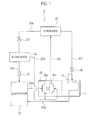
- the electrical motor 1 is provided as a drive source for a turbo compressor 20 in a refrigeration cycle of a turbo refrigerator 2.
- the turbo refrigerator 2 is an apparatus for preparing coolant for air conditioning.
- the turbo refrigerator 2 includes an evaporator 21, a condenser 22 and an economizer 26. These components are connected with each other by refrigerant pipes 25a to 25e to circulate refrigerant (cooling fluid: chlorofluorocarbon).
- the condenser 22 is connected with the compressor 20 via a flow path 25a, and connected with the economizer 26 via a flow path 25b on which an expansion valve (pressure reducer) 23 is provided.
- Refrigerant gas compressed by the compressor 20 is supplied to the condenser 22 through the flow path 25a.
- the condenser 22 condenses the compressed refrigerant gas into refrigerant liquid (some remains as refrigerant gas).
- the refrigerant liquid condensed by the condenser 22 (or refrigerant in a gas-liquid mixed state) is decompressed by the expansion valve 23 through the flow path 25b, and then supplied to the economizer 26.
- the economizer 26 is connected with the evaporator 21 via a flow path 25c on which an expansion valve (pressure reducer) 27 is provided, and connected with the compressor 20 via a flow path 25d.
- the economizer 26 temporarily accumulates the refrigerant liquid (part thereof is refrigerant gas) decompressed by the expansion valve (pressure reduction valve) 23 on the flow path 25c.
- Gas-phase component (refrigerant gas) of the refrigerant liquid (gas-liquid mixed state) accumulated by the economizer 26 is supplied to a second compression stage (second impeller) 20b of the compressor 20 via the flow path 25d.
- liquid-phase component of the refrigerant liquid (gas-liquid mixed state) accumulated by the economizer 26 is decompressed by the expansion valve 27 on the flow path 25c, and then supplied to the evaporator 21.
- the evaporator 21 is connected with a first compression stage (first impeller) 20a of the compressor 20 via a flow path 25e.
- the evaporator 21 evaporates the refrigerant liquid decompressed by the expansion valve 27 on the flow path 25c into refrigerant gas.
- the refrigerant gas evaporated by the evaporator 21 is supplied to the first compression stage 20a of the compressor 20 via the flow path 21e.
- the compressor 20 is connected with the condenser 22 via the flow path 25a, and has the first compression stage 20a and the second compression stage 20b that are explained above.
- the compressor 20 compresses the refrigerant gas supplied via the flow path 25e by the first compression stage 20a and then discharges it to the flow path 25d, and concurrently compresses the refrigerant gas supplied via the flow path 25d (containing the refrigerant gas discharged from the first compression stage 20a) by the second compression stage 20b and then discharges it to the flow path 25a.
- the refrigerant gas compressed by the compressor 20 is supplied to the condenser 22 via the flow path 25a.
- the coolant for air conditioning is cooled by heat-exchanging with the refrigerant at the evaporator 21.
- the turbo refrigerator 2 in the present embodiment includes, in addition to the above-explained refrigeration cycle, a cooling system for the electrical motor 1 that utilizes the refrigerant of the refrigeration cycle.
- the refrigerant liquid (or the refrigerant in a gas-liquid mixed state) condensed by the condenser 22 is supplied to the electrical motor 1 via a flow path 25f.
- a supply amount of the refrigerant liquid to the electrical motor 1 is controlled by a regulator 24 (such as a flow control valve and an orifice).
- the refrigerant liquid supplied to the electrical motor 1 cools the electrical motor 1, and then is returned to the evaporator 21 (the refrigeration cycle).
- part of the refrigerant liquid circulates around a stator 5 (see Fig. 4 ), and remaining part thereof is sprayed to an inside of the electrical motor 1 from an after-explained first spray nozzle 7a.
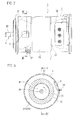
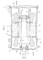
- the electrical motor 1 will be explained in detail. As shown in Fig. 2 to Fig. 4 , the electrical motor 1 includes a die-cast motor case 3, a rotor 4 rotatable about a rotor shaft 40, and a stator 5 provided around the rotor 4.
- the motor case 3 is configured of a cylindrical circumferential wall 31, and an end wall 32 and a pass-through wall 33 that close both ends of the circumferential wall 31, respectively.
- An inner chamber 34 is formed within the motor case 3 (the circumferential wall 31, the end wall 32 and the pass-through wall 33).
- the stator 5 is fixed with an inner surface of the circumferential wall 31.
- a support cylinder 32a is protruded from the center of the end wall 32 toward the inner chamber 34.
- a ball bearing 60A and a labyrinth seal 61A are provided at an end of the support cylinder 32a.
- a cylindrical hole 33a is formed at the center of the pass-through wall 33.
- a roller bearing 60B and a labyrinth seal 61B are provided at the cylindrical hole 33a.
- the ball bearing 60A and the roller bearing 60B supports the rotor shaft 40 rotatably.
- the inner chamber 34 is segmented, by the rotor 4 and the stator 5, into a first chamber 34A located on one side (left side in Fig. 4 ) of the rotor 4 and the stator 5, and a second chamber 34B located on another side (right side in Fig. 4 ) thereof.
- a first spray nozzle 7a for spraying refrigerant liquid 8 toward an inner circumferential surface 30 of the first chamber 34A is provided on the motor case 3.
- the first spray nozzle 7a is disposed along a radial direction of the motor case 3 toward a first coil end 51 protruded into the first chamber 34A.
- the first spray nozzle 7a will be explained later in detail. Note that, in Fig. 4 , the first spray nozzle 7a is indicated by dotted lines, because it locates on a near side from a cross-sectional plane.
- the stator 5 includes a cylindrical stator core 53 in which plural magnetic steel sheets are stacked and a stator coil 50 wound around teeth of the stator core 53. An insulation coating such as varnish is formed on a surface of the stator coil 50.
- the stator coil 50 has a first coil end protruded into the first chamber 34A along an axial direction of the rotor shaft 40, and a second coil end 52 protruded into the second chamber 34B along the axial direction of the rotor shaft 40.
- the rotor 4 includes a rotor shaft 40, a cylindrical rotor core 41 in which plural magnetic steel sheets are stacked, and a rotor coil wound around the rotor core 41.
- the rotor shaft 40 penetrates the rotor core 41, and is fixed with the rotor core 41.
- the rotor 4 is disposed within the stator 5, and rotatably supported by the end wall 32 and the pass-through wall 33 with the rotor shaft 40 and the bearings 60A and 60B interposed therebetween.
- the stator 5 is provided around the rotor 4 in the motor case 3.
- a refrigerant flow passage 35 is provided in the electrical motor 1.
- the refrigerant flow passage 35 circulates the refrigerant liquid 8 supplied from outside through the inside of the electrical motor 1.
- the refrigerant flow passage 35 is configured of a spiral groove formed on the inner circumferential surface 30 of the circumferential wall 31 so as to face the stator coil 53.
- the stator coil 53 is cooled by the refrigerant liquid 8 while the refrigerant liquid 8 flows through the refrigerant flow passage 35.
- the first spray nozzle 7a has, in its inside, a supply passage 70 extended along its axial direction, and an injection port 71 formed at its end as a slit.
- the supply passage 70 supplies, to the injection port 71, the refrigerant liquid 8 supplied from an outside of the motor case 3.
- the supplied refrigerant liquid 8 is sprayed out from the injection port 71 toward the inner circumferential surface 30 of the motor case 3.
- an open direction of the injection port 71 is set to a predetermined inclination angle A1 with respect to the axial direction of the first spray nozzle 7a.
- the refrigerant liquid 8 is sprayed out toward the inner circumferential surface 30 of the motor case 3 by the inclination angle A1.
- the sprayed refrigerant liquid 8 keeps the inclination angle A1 and a thickness of its sprayed range is made almost constant.
- the injection port 71 of the first spray nozzle 7a is formed as the slit extended along an axial direction of the rotor shaft 40. Therefore, the sprayed refrigerant liquid 8 spreads like a fan along a plane parallel to the axial direction of the rotor shaft 40 (a central angle of the fan is a spread angle A2).
- An attachment position to the motor case 3, the inclination angle A1 and the spread angle A2 of the first spray nozzle 7a are set according to a size of the electrical motor 1 and an injection pressure of the refrigerant liquid 8 so that the refrigerant liquid 8 is spread to a wide range and refrigerant mists (refrigerant droplets) 8 splashed by the internal circumferential surface 30 falls over an entire of the first coil end 51.
- cooling by the refrigerant flow passage 35 is explained with reference to Fig. 4 .
- the refrigerant liquid 8 supplied form an outside of the motor case 3 to the refrigerant flow passage 35 is evaporated by heat of the stator coil 53 while flowing through the refrigerant flow passage 35, and thereby cools the stator coil 53 by its vaporization heat.
- the refrigerant liquid 8 passing through the refrigerant flow passage 35 is discharged into the second chamber 34B.
- the refrigerant liquid 8 discharged into the second chamber 34B falls over the second coil end 52 and vaporized by heat of the second coil end 52, and thereby cools the second coil end 52 by its vaporization heat.
- Inner pressure of the second chamber 34B rises due to the refrigeration gas 8 generated by vaporization of the refrigerant liquid 8, and the refrigeration gas 8 transfers to the low-pressure first chamber 34A through a gap between the stator coil 53 and the rotor coil 41.
- part of the refrigerant liquid (refrigerant mist) 8 discharged into the second chamber 34B and the refrigerant liquid 8 accumulated at a lower portion in the second chamber 34B also transfers to the first chamber 34A through the gap between the stator coil 53 and the rotor coil 41.
- the rotor 4 (and the stator 5) is cooled by the refrigerant 8 along with the above-explained transfer of the refrigerant 8 from the second chamber 34B to the first chamber 34A.
- the first spray nozzle 7a is provided in order to cool the first coil end 51 in the first chamber 34A by the refrigerant liquid 8.
- the refrigerant liquid 8 is sprayed out from the injection port 71 of the first spray nozzle 7a toward the inner circumferential surface 30 of the first chamber 34A, the refrigerant liquid 8 is splashed by the inner circumferential surface 30 and then spread to a wide range as the refrigerant mist (refrigerant droplets) 8.
- a surface pattern of a casting mold for the die-cast motor case 3 is transferred to the inner circumferential surface 30, so that the inner circumferential surface 30 has fine asperity. Therefore, the inner circumferential surface 30 can splash the refrigerant liquid 8 preferably as the refrigerant mist (refrigerant droplets) 8.
- the spread refrigerant mist 8 falls downward due to gravity to fall over the first coil end 51 and is vaporized by heat of the first coil end 51, and thereby cools the first coil end 51 by its vaporization heat.
- the first spray nozzle 7a (the injection port 71) is located at almost a middle position of a protrusion length of the first coil end 51.
- the refrigerant liquid 8 is sprayed along a rotational direction of the rotor 4 (counter-clockwise direction in Fig. 2 ) from the first spray nozzle 7a (the injection port 71).
- a rotating flow flowing to the rotational direction is formed in the motor case 3 by rotations of the rotor 4. Therefore, the refrigerant mist 8 splashed by the inner circumferential surface 30 is carried to an entire of the first coil end 51 by the rotating flow when the refrigerant liquid is sprayed in the rotational direction of the rotor 4, so that the entire of the first coil end 51 (and other portions in the first chamber 34A) can be cooled.
- cooling effect to the first coil end 51 can be further improved.
- the refrigerant liquid 8 that is sprayed from the first spray nozzle 7a and not vaporized is flows downward, and then discharged to the flow path 25g (see Fig. 1 ) from a drain 37 together with the refrigerant gas 8 via a groove 36 provided at a lower portion of the circumferential wall 31.
- the refrigerant mist 8 is generated by spraying the refrigerant liquid 8 from the first spray nozzle 7a toward the inner circumferential surface 30 to cool the first coil end 51 directly by the refrigerant mist 8. Therefore, the first coil end 51 can be cooled more sufficiently than a conventional way in which a coil end is cooled mainly by heat conduction. As a result, burnouts and seizures caused by temperature increase of the electrical motor 1 can be prevented.
- the refrigerant mist 8 reaches the first coil end 51 at low speed. Therefore, the insulation coating of the first coil end 51 can be prevented from being damaged. Further, the refrigerant mist 8 can be spread to a wide range by splashing the refrigerant liquid 8 by using the inner circumferential surface 30, so that an entire of the first coil end 51 can be cooled by the refrigerant mist 8. Furthermore, since the refrigerant liquid 8 is sprayed from the injection port 71 formed as a slit and spread like a fan, the refrigerant mist 8 can be made spread to a wide range along the protrusion direction of the first coil end 51 and thereby the first coil end 51 can be cooled efficiently.
- a first chamber in which the first spray nozzle 7a is provided for generating the refrigerant mist 8 to be fallen over the first coil end 51 is the first chamber 34A on an output side of a drive force of the electrical motor 1 (a side on which the rotor shaft 40 is extended out from the motor case 3: left side in Fig. 4 ).
- the first spray nozzle 7a may be provided in the chamber 34B on an opposite side to the output side of the electrical motor 1 (i.e. the chamber 34B is the first chamber).
- the first spray nozzle for generating the refrigerant mist 8 to be fallen over the first coil end 51 may be provided in each of both chambers.
- the refrigerant liquid 8 from the refrigerant flow passage 35 is discharged into the chamber (second chamber 34B) on an opposite side to the output side of the electrical motor 1.
- the refrigerant flow passage 35 may be formed so that the refrigerant liquid 8 is discharged into the chamber 34A on the output side of the electrical motor 1.
- the first spray nozzle for generating refrigerant mist it is preferable that the first spray nozzle for generating refrigerant mist to be fallen over the coil end 52 (i.e. the chamber 34B is the first chamber).
- an electrical motor 1 (a turbo compressor 20) according to a second embodiment will be explained with reference to Fig. 7 to Fig. 9 .
- the present embodiment has a configuration whose cooling performance is further improved than that in the above-explained first embodiment.
- a second spray nozzle 7b and a gas injection nozzle 9 are added to the configuration of the first embodiment in order to improve the cooling performance. Since other components are similar to those in the first embodiment, identical and equivalent components will be labeled by identical reference numbers and their redundant explanations will be omitted.
- a flow of the refrigerant 8 (refrigerant gas and refrigerant liquid) from the second chamber 34B to the first chamber 34A is generated in the inside of the motor case 3, and the rotor 4 (and the stator 5) is cooled by the flow.
- high-pressure gas is injected into the second chamber 34B in order to increase an amount of the flow of the refrigerant 8.
- the gas injection nozzle 9 for injecting high-pressure gas into the second chamber 34B is provided on the motor case 3. Note that, in Fig. 8 , the gas injection nozzle 9 is indicated by dotted lines, because it locates behind the support cylinder 32a.
- the high-pressure refrigerant gas 8 is supplied to the gas injection nozzle 9 from a downstream side of the second compression stage (second impeller) 20b of the compressor 20. Pressure of the refrigerant gas 8 on the downstream side of the second compression stage (second impeller) 20b is high in the refrigeration cycle of the turbo refrigerator 2, so that it is preferable as the high-pressure gas.
- the high-pressure gas injected into the inside of the second chamber 34B is the identical refrigerant (high-pressure refrigerant gas) 8.
- Pressure in the second chamber 34B is made high by the injection of the high-pressure refrigerant gas 8 into the second chamber 34b, so that the flow of the refrigerant 8 (refrigerant gas and refrigerant liquid) from the second chamber 34B to the first chamber 34A is made predominant.
- the flow of the refrigerant predominant a heat-exchanging amount between the refrigerant 8 and the rotor 4 (and the stator 5) increases and thereby the cooling performance increases.
- configuration of the gas injection nozzle 9 is basically identical to configuration of the above-explained first spray nozzle 7a, its detailed explanations are omitted here.
- the first spray nozzle 7a injects refrigerant liquid
- the gas injection nozzle 9 injects high-pressure gas (high-pressure refrigerant gas). Therefore, a cross-sectional area of an inner flow passage and a shape of an injection port of the gas injection nozzle 9 are optimized for high-pressure gas.
- the injection port 71 of the first spray nozzle 7a is formed as a slit in order to spread refrigerant liquid to a wide range.
- the injection port of the gas injection nozzle 9 may not be formed as a slit but as a circular hole.
- the second spray nozzle 7b having an identical configuration to that of the first spray nozzle 7a is provided in order to increase the refrigerant mist 8 contained in the flow of the refrigerant 8 from the second chamber 34B to the first chamber 34A. Since vaporization heat becomes increased when the refrigerant mist 8 contained in the flow of the refrigerant 8 increases, the heat-exchanging amount between the refrigerant 8 and the rotor 4 (and the stator 5) further increases and thereby the cooling performance further improves.
- the second spray nozzle 7b is provided on an opposite side to the gas injection nozzle 9 with respect to the rotor shaft 40 (on the same side as the first spray nozzle 7a).
- the second spray nozzle 7b has an identical configuration to that of the first spray nozzle 7a (see Fig. 5 and Fig. 6 ), and sprays the refrigerant liquid 8 toward the inner circumferential surface 30 of the second chamber 34B.
- the sprayed refrigerant liquid 8 is splashed by the inner circumferential surface 30 to become the refrigerant mist 8, and then spread in the second chamber 34B.
- the spread refrigerant mist 8 is moved from the second chamber 34B to the first chamber 34A due to the flow of the refrigerant 8 made predominant by the refrigerant gas 8 (high-pressure gas) injected from the gas injection nozzle 9, and thereby exchanges heats with the rotor 4 (and the stator 5) to improve the cooling performance.
- the refrigerant gas 8 high-pressure gas
- the second spray nozzle 7b also spray the refrigerant liquid 8 along the rotational direction of the rotor 4 (counter-clockwise direction in Fig. 9 ). Since the rotating flow is formed along the rotational direction of the rotor 4 in the motor case 3 as explained above, the generated refrigerant mist 8 is agitated by the rotating flow when the refrigerant liquid 8 is sprayed in the rotational direction of the rotor 4 and thereby it becomes easily contained in the flow of the refrigerant 8 from the second chamber 34B to the first chamber 34A.
- the gas injection nozzle 9 also injects the refrigerant gas 8 (high-pressure gas) along the rotational direction of the rotor 4. Therefore, the rotating flow is made predominant, and thereby the generated refrigerant mist 8 is further agitated. As a result, the refrigerant mist 8 becomes easily contained in the flow of the refrigerant 8 from the second chamber 34B to the first chamber 34A further. In addition, since the refrigerant mist 8 is spread further uniformly, an entire of the rotor 4 can be cooled. Note that the refrigerant 8 discharged from the refrigerant flow passage 35 is also spread due to the predominant rotating flow by the gas injection nozzle 9 and thereby the second coil end 52 can be also cooled effectively.
- the refrigerant gas 8 high-pressure gas
- the gas injection nozzle 9 is configured to inject the refrigerant gas 8 (high-pressure gas) toward an outside from an end edge of the second coil end 52 (outer side from its protrusion: right side in Fig. 8 ) in order to generate the flow of the refrigerant 8 from the second chamber 34B toward an inside of the second coil end effectively.
- the flow amount of the refrigerant 8 from the second chamber 34B to the first chamber 34A can be increased effectively.
- the gas injection nozzle 9 is configured to inject the refrigerant gas 8 (high-pressure gas) toward the outside from the end edge of the second coil end 52, so that prevented can be damages of the insulation coating of the second coil end 52 caused by the refrigerant gas 8 (high-pressure gas) injected from the gas injection nozzle 9.
- the gas injection nozzle 9 itself is disposed outside the end edge of the second coil end 52 (at a position of the cross-sectional plane IX-IX in Fig. 8 ).
- the first spray nozzle 7a is located at almost the middle position of a protrusion length of the first coil end 51.
- principal purpose of the second spray nozzle 7b is spreading the generated refrigerant mist 8 in the second chamber 34B in order to make it contained into the flow of the refrigerant 8 from the second chamber 34B to the first chamber 34A. Therefore, in the present embodiment, the second spray nozzle 7b is disposed, along the axial direction of the rotor shaft 40, at the same position as the gas injection nozzle 9 (at the position of the cross-sectional plane IX-IX in Fig. 8 ).
- the refrigerant mist 8 generated by the second spray nozzle 7b can be sufficiently spread into the second chamber 34B by being splashed by the inner circumferential surface 30, it may be disposed inside the end edge of the second coil end 52. In addition, part of the refrigerant mist 8 generated by the second spray nozzle 7b may be made fallen over the second coil end 52 to cool the second coil end 52.
- the refrigerant gas 8 as high-pressure gas injected from the gas inj ection nozzle 9 is taken from a downstream side of the second compression stage (second impeller) 20b of the compressor 20.
- pressure may be taken from a downstream side of the first compression stage (first impeller) 20a (i.e. from an upstream side of the second compression stage 20b).
- the present embodiment includes all the configurations of the first embodiment, and all the advantages achieved by the first embodiment can be achieved by the present embodiment. Further, according to the present embodiment, pipes for the gas injection nozzle 9 and the second spray nozzle 7b increases, but the cooling performance (especially, cooling of the rotor 5) can be further improved. It may be determined in consideration of heat generation property of the electrical motor 1 whether or not the gas injection nozzle 9 and the second spray nozzle 7b are required.
Landscapes
- Engineering & Computer Science (AREA)
- Power Engineering (AREA)
- Physics & Mathematics (AREA)
- Thermal Sciences (AREA)
- Mechanical Engineering (AREA)
- General Engineering & Computer Science (AREA)
- Motor Or Generator Cooling System (AREA)
- Structures Of Non-Positive Displacement Pumps (AREA)
Abstract
Description
- The present invention relates to an electrical motor that includes a rotor and a stator provided around the rotor to cool the stator by liquid coolant, and to a turbo compressor using the electrical motor.
- Conventionally, known is an electrical motor whose inside is cooled by using liquid coolant (refrigerant) in order to prevent burnouts of coils or insulating materials and thermal deformation of its rotor caused by temperature increase of its stator or its rotor at a long time operation of the electrical motor. A
Patent Document 1 listed below discloses an electrical motor in which refrigerant liquid is supplied to an inside of its rotating cylindrical bottomed rotor. In this electrical motor, the rotor is cooled by vaporization heat of the refrigerant liquid. In addition, aPatent Document 2 listed below discloses an electrical motor in which a refrigerant supply amount is controlled. In this electrical motor, excessive cooling and lubrication failure caused by mixture of refrigerant liquid into lubrication oil can be prevented by controlling the refrigerant supply amount. -
- Patent Document 1: Japanese Patent Application Publication No.
2009-118693 - Patent Document 2: Japanese Patent Application Publication No.
2009-300008 - In the above electrical motors, the rotor is cooled, but the stator is not cooled sufficiently. Refrigerant liquid that isn't vaporized at the rotor falls over the stator while it drips down to a drain, and the stator is cooled only by this refrigerant liquid. Especially in the electrical motor disclosed by the
Patent Document 1, a coil end on a bottom side of the rotor is cooled only by heat conduction, so that it can't be cooled sufficiently. Therefore, burnout possibility of the electrical motor cannot be resolved. - An object of the present invention is to provide an electrical motor that can cool a coil end(s) of a stator coil sufficiently.
- A first aspect of the present invention provides an electrical motor comprising: a motor case; a rotor that is housed in the motor case and rotatable about a rotor shaft; a stator that is provided around the rotor in the motor case and configured by winding a stator coil around a stator core; and a first spray nozzle that is provided in the motor case for spraying liquid coolant toward an inner circumferential surface of the motor case, wherein the stator coil has a first coil end protruded from the stator core along a direction of the rotor shaft, and the first spray nozzle is configured to spread the coolant as mist by splashing the coolant on the inner circumferential surface to make the spread mist over the first coil end.
- In the above first aspect, the coolant is sprayed from the first spray nozzle toward the inner circumferential surface of the motor case, and the coolant is splashed on the inner circumferential surface to be spread as mist. The spread mist coolant falls over the first coil end, and cools the coil end by its vaporization heat. Therefore, the first coil end can be cooled more sufficiently than in a case of cooling the coil end by heat conduction, and thereby burnouts possibility caused by temperature increase of the electrical motor can be prevented. As a result, reliability of the electrical motor can be improved. In addition, the generated mist coolant falls over the first coil end at low speed, so that an insulation coating of the first coil end can be prevented from being damaged.
- A second aspect of the present invention provides a turbo compressor for driving an impeller by the electrical according to the above first aspect, wherein an inside of the motor case is segmented into a first chamber located on one side of the rotor and the stator and a second chamber on another side of the rotor and the stator, the first coil end is protruded into the first chamber, the first spray nozzle is provided in the first chamber to spray the coolant into the first chamber, the electrical motor further comprises a gas injection nozzle for injecting high-pressure gas into the second chamber, and the high-pressure gas is the gas coolant compressed by the impeller.
-
- [
Fig. 1 ] It is a block diagram of a refrigeration cycle including an electrical motor (a turbo compressor) according to a first embodiment. - [
Fig. 2 ] It is a side view of the electrical motor. - [
Fig. 3 ] It is a cross-sectional view taken along a line III-III shown inFig. 2 . - [
Fig. 4 ] It is a cross-sectional view taken along a line IV-IV shown inFig. 3 . - [
Fig. 5 ] It is a plan view of a nozzle in the electrical motor. - [
Fig. 6 ] It is a cross-sectional view taken along a line VI-VI shown inFig. 5 . - [
Fig. 7 ] It is a block diagram of a refrigeration cycle including an electrical motor (a turbo compressor) according to a second embodiment. - [
Fig. 8 ] It is a vertical cross-sectional view of the electrical motor. - [
Fig. 9 ] It is a cross-sectional view taken along a line IX-IX shown inFig. 8 . - Hereinafter, embodiments will be explained with reference to the drawings. First, an electrical motor 1 (a turbo compressor 20) according to a first embodiment will be explained with reference to
Fig. 1 to Fig. 6 . - As shown in
Fig. 1 , theelectrical motor 1 is provided as a drive source for aturbo compressor 20 in a refrigeration cycle of aturbo refrigerator 2. Theturbo refrigerator 2 is an apparatus for preparing coolant for air conditioning. Theturbo refrigerator 2 includes anevaporator 21, acondenser 22 and aneconomizer 26. These components are connected with each other byrefrigerant pipes 25a to 25e to circulate refrigerant (cooling fluid: chlorofluorocarbon). - The
condenser 22 is connected with thecompressor 20 via aflow path 25a, and connected with theeconomizer 26 via aflow path 25b on which an expansion valve (pressure reducer) 23 is provided. Refrigerant gas compressed by thecompressor 20 is supplied to thecondenser 22 through theflow path 25a. Thecondenser 22 condenses the compressed refrigerant gas into refrigerant liquid (some remains as refrigerant gas). The refrigerant liquid condensed by the condenser 22 (or refrigerant in a gas-liquid mixed state) is decompressed by theexpansion valve 23 through theflow path 25b, and then supplied to theeconomizer 26. - The
economizer 26 is connected with theevaporator 21 via aflow path 25c on which an expansion valve (pressure reducer) 27 is provided, and connected with thecompressor 20 via aflow path 25d. Theeconomizer 26 temporarily accumulates the refrigerant liquid (part thereof is refrigerant gas) decompressed by the expansion valve (pressure reduction valve) 23 on theflow path 25c. Gas-phase component (refrigerant gas) of the refrigerant liquid (gas-liquid mixed state) accumulated by theeconomizer 26 is supplied to a second compression stage (second impeller) 20b of thecompressor 20 via theflow path 25d. On the other hand, liquid-phase component of the refrigerant liquid (gas-liquid mixed state) accumulated by theeconomizer 26 is decompressed by theexpansion valve 27 on theflow path 25c, and then supplied to theevaporator 21. - The
evaporator 21 is connected with a first compression stage (first impeller) 20a of thecompressor 20 via aflow path 25e. Theevaporator 21 evaporates the refrigerant liquid decompressed by theexpansion valve 27 on theflow path 25c into refrigerant gas. The refrigerant gas evaporated by theevaporator 21 is supplied to thefirst compression stage 20a of thecompressor 20 via the flow path 21e. - The
compressor 20 is connected with thecondenser 22 via theflow path 25a, and has thefirst compression stage 20a and thesecond compression stage 20b that are explained above. Thecompressor 20 compresses the refrigerant gas supplied via theflow path 25e by thefirst compression stage 20a and then discharges it to theflow path 25d, and concurrently compresses the refrigerant gas supplied via theflow path 25d (containing the refrigerant gas discharged from thefirst compression stage 20a) by thesecond compression stage 20b and then discharges it to theflow path 25a. The refrigerant gas compressed by thecompressor 20 is supplied to thecondenser 22 via theflow path 25a. The coolant for air conditioning is cooled by heat-exchanging with the refrigerant at theevaporator 21. - The
turbo refrigerator 2 in the present embodiment includes, in addition to the above-explained refrigeration cycle, a cooling system for theelectrical motor 1 that utilizes the refrigerant of the refrigeration cycle. The refrigerant liquid (or the refrigerant in a gas-liquid mixed state) condensed by thecondenser 22 is supplied to theelectrical motor 1 via aflow path 25f. On theflow path 25f, a supply amount of the refrigerant liquid to theelectrical motor 1 is controlled by a regulator 24 (such as a flow control valve and an orifice). The refrigerant liquid supplied to theelectrical motor 1 cools theelectrical motor 1, and then is returned to the evaporator 21 (the refrigeration cycle). In theelectrical motor 1, part of the refrigerant liquid circulates around a stator 5 (seeFig. 4 ), and remaining part thereof is sprayed to an inside of theelectrical motor 1 from an after-explainedfirst spray nozzle 7a. - The
electrical motor 1 will be explained in detail. As shown inFig. 2 to Fig. 4 , theelectrical motor 1 includes a die-cast motor case 3, arotor 4 rotatable about arotor shaft 40, and a stator 5 provided around therotor 4. - The
motor case 3 is configured of a cylindricalcircumferential wall 31, and anend wall 32 and a pass-throughwall 33 that close both ends of thecircumferential wall 31, respectively. Aninner chamber 34 is formed within the motor case 3 (thecircumferential wall 31, theend wall 32 and the pass-through wall 33). The stator 5 is fixed with an inner surface of thecircumferential wall 31. Asupport cylinder 32a is protruded from the center of theend wall 32 toward theinner chamber 34. Aball bearing 60A and alabyrinth seal 61A are provided at an end of thesupport cylinder 32a. On the other hand, acylindrical hole 33a is formed at the center of the pass-throughwall 33. Aroller bearing 60B and alabyrinth seal 61B are provided at thecylindrical hole 33a. The ball bearing 60A and theroller bearing 60B supports therotor shaft 40 rotatably. - The
inner chamber 34 is segmented, by therotor 4 and the stator 5, into afirst chamber 34A located on one side (left side inFig. 4 ) of therotor 4 and the stator 5, and asecond chamber 34B located on another side (right side inFig. 4 ) thereof. As shown inFig. 3 andFig. 4 , afirst spray nozzle 7a for sprayingrefrigerant liquid 8 toward an innercircumferential surface 30 of thefirst chamber 34A is provided on themotor case 3. Thefirst spray nozzle 7a is disposed along a radial direction of themotor case 3 toward afirst coil end 51 protruded into thefirst chamber 34A. Thefirst spray nozzle 7a will be explained later in detail. Note that, inFig. 4 , thefirst spray nozzle 7a is indicated by dotted lines, because it locates on a near side from a cross-sectional plane. - The stator 5 includes a
cylindrical stator core 53 in which plural magnetic steel sheets are stacked and astator coil 50 wound around teeth of thestator core 53. An insulation coating such as varnish is formed on a surface of thestator coil 50. In addition, thestator coil 50 has a first coil end protruded into thefirst chamber 34A along an axial direction of therotor shaft 40, and asecond coil end 52 protruded into thesecond chamber 34B along the axial direction of therotor shaft 40. - The
rotor 4 includes arotor shaft 40, acylindrical rotor core 41 in which plural magnetic steel sheets are stacked, and a rotor coil wound around therotor core 41. Therotor shaft 40 penetrates therotor core 41, and is fixed with therotor core 41. In addition, therotor 4 is disposed within the stator 5, and rotatably supported by theend wall 32 and the pass-throughwall 33 with therotor shaft 40 and thebearings rotor 4 in themotor case 3. - In addition, a
refrigerant flow passage 35 is provided in theelectrical motor 1. Therefrigerant flow passage 35 circulates therefrigerant liquid 8 supplied from outside through the inside of theelectrical motor 1. Therefrigerant flow passage 35 is configured of a spiral groove formed on the innercircumferential surface 30 of thecircumferential wall 31 so as to face thestator coil 53. Thestator coil 53 is cooled by therefrigerant liquid 8 while therefrigerant liquid 8 flows through therefrigerant flow passage 35. - As shown in
Fig. 5 and Fig. 6 , thefirst spray nozzle 7a has, in its inside, asupply passage 70 extended along its axial direction, and aninjection port 71 formed at its end as a slit. Thesupply passage 70 supplies, to theinjection port 71, therefrigerant liquid 8 supplied from an outside of themotor case 3. The suppliedrefrigerant liquid 8 is sprayed out from theinjection port 71 toward the innercircumferential surface 30 of themotor case 3. - As shown in
Fig. 6 , an open direction of theinjection port 71 is set to a predetermined inclination angle A1 with respect to the axial direction of thefirst spray nozzle 7a. Therefrigerant liquid 8 is sprayed out toward the innercircumferential surface 30 of themotor case 3 by the inclination angle A1. Here, the sprayedrefrigerant liquid 8 keeps the inclination angle A1 and a thickness of its sprayed range is made almost constant. In addition, theinjection port 71 of thefirst spray nozzle 7a is formed as the slit extended along an axial direction of therotor shaft 40. Therefore, the sprayedrefrigerant liquid 8 spreads like a fan along a plane parallel to the axial direction of the rotor shaft 40 (a central angle of the fan is a spread angle A2). - An attachment position to the
motor case 3, the inclination angle A1 and the spread angle A2 of thefirst spray nozzle 7a are set according to a size of theelectrical motor 1 and an injection pressure of therefrigerant liquid 8 so that therefrigerant liquid 8 is spread to a wide range and refrigerant mists (refrigerant droplets) 8 splashed by the internalcircumferential surface 30 falls over an entire of thefirst coil end 51. - Cooling operations will be explained. First, cooling by the
refrigerant flow passage 35 is explained with reference toFig. 4 . Therefrigerant liquid 8 supplied form an outside of themotor case 3 to therefrigerant flow passage 35 is evaporated by heat of thestator coil 53 while flowing through therefrigerant flow passage 35, and thereby cools thestator coil 53 by its vaporization heat. Therefrigerant liquid 8 passing through therefrigerant flow passage 35 is discharged into thesecond chamber 34B. Therefrigerant liquid 8 discharged into thesecond chamber 34B falls over thesecond coil end 52 and vaporized by heat of thesecond coil end 52, and thereby cools thesecond coil end 52 by its vaporization heat. - Inner pressure of the
second chamber 34B rises due to therefrigeration gas 8 generated by vaporization of therefrigerant liquid 8, and therefrigeration gas 8 transfers to the low-pressurefirst chamber 34A through a gap between thestator coil 53 and therotor coil 41. Note that part of the refrigerant liquid (refrigerant mist) 8 discharged into thesecond chamber 34B and therefrigerant liquid 8 accumulated at a lower portion in thesecond chamber 34B also transfers to thefirst chamber 34A through the gap between thestator coil 53 and therotor coil 41. The rotor 4 (and the stator 5) is cooled by therefrigerant 8 along with the above-explained transfer of the refrigerant 8 from thesecond chamber 34B to thefirst chamber 34A. - Next, cooling by the
first spray nozzle 7a is explained. As explained above, thesecond coil end 52 in thesecond chamber 34B (and the stator 5) is cooled by therefrigerant 8 flowing through therefrigerant flow passage 35. On the other hand, thefirst spray nozzle 7a is provided in order to cool thefirst coil end 51 in thefirst chamber 34A by therefrigerant liquid 8. When therefrigerant liquid 8 is sprayed out from theinjection port 71 of thefirst spray nozzle 7a toward the innercircumferential surface 30 of thefirst chamber 34A, therefrigerant liquid 8 is splashed by the innercircumferential surface 30 and then spread to a wide range as the refrigerant mist (refrigerant droplets) 8. - A surface pattern of a casting mold for the die-
cast motor case 3 is transferred to the innercircumferential surface 30, so that the innercircumferential surface 30 has fine asperity. Therefore, the innercircumferential surface 30 can splash therefrigerant liquid 8 preferably as the refrigerant mist (refrigerant droplets) 8. The spread refrigerantmist 8 falls downward due to gravity to fall over thefirst coil end 51 and is vaporized by heat of thefirst coil end 51, and thereby cools thefirst coil end 51 by its vaporization heat. Note that, in order to make therefrigerant mist 8 fallen over thefirst coil end 51 efficiently, it is preferable that thefirst spray nozzle 7a (the injection port 71) is located at almost a middle position of a protrusion length of thefirst coil end 51. - In addition, the
refrigerant liquid 8 is sprayed along a rotational direction of the rotor 4 (counter-clockwise direction inFig. 2 ) from thefirst spray nozzle 7a (the injection port 71). A rotating flow flowing to the rotational direction is formed in themotor case 3 by rotations of therotor 4. Therefore, therefrigerant mist 8 splashed by the innercircumferential surface 30 is carried to an entire of thefirst coil end 51 by the rotating flow when the refrigerant liquid is sprayed in the rotational direction of therotor 4, so that the entire of the first coil end 51 (and other portions in thefirst chamber 34A) can be cooled. As a result, cooling effect to thefirst coil end 51 can be further improved. Note that therefrigerant liquid 8 that is sprayed from thefirst spray nozzle 7a and not vaporized is flows downward, and then discharged to theflow path 25g (seeFig. 1 ) from adrain 37 together with therefrigerant gas 8 via agroove 36 provided at a lower portion of thecircumferential wall 31. - According to the
electrical motor 1 in the present embodiment, therefrigerant mist 8 is generated by spraying therefrigerant liquid 8 from thefirst spray nozzle 7a toward the innercircumferential surface 30 to cool thefirst coil end 51 directly by therefrigerant mist 8. Therefore, thefirst coil end 51 can be cooled more sufficiently than a conventional way in which a coil end is cooled mainly by heat conduction. As a result, burnouts and seizures caused by temperature increase of theelectrical motor 1 can be prevented. - In addition, the
refrigerant mist 8 reaches thefirst coil end 51 at low speed. Therefore, the insulation coating of thefirst coil end 51 can be prevented from being damaged. Further, therefrigerant mist 8 can be spread to a wide range by splashing therefrigerant liquid 8 by using the innercircumferential surface 30, so that an entire of thefirst coil end 51 can be cooled by therefrigerant mist 8. Furthermore, since therefrigerant liquid 8 is sprayed from theinjection port 71 formed as a slit and spread like a fan, therefrigerant mist 8 can be made spread to a wide range along the protrusion direction of thefirst coil end 51 and thereby thefirst coil end 51 can be cooled efficiently. - Note that, in the above embodiment, a first chamber in which the
first spray nozzle 7a is provided for generating therefrigerant mist 8 to be fallen over thefirst coil end 51 is thefirst chamber 34A on an output side of a drive force of the electrical motor 1 (a side on which therotor shaft 40 is extended out from the motor case 3: left side inFig. 4 ). However, as necessary, thefirst spray nozzle 7a may be provided in thechamber 34B on an opposite side to the output side of the electrical motor 1 (i.e. thechamber 34B is the first chamber). Or, the first spray nozzle for generating therefrigerant mist 8 to be fallen over thefirst coil end 51 may be provided in each of both chambers. - In addition, in the above embodiment, the
refrigerant liquid 8 from therefrigerant flow passage 35 is discharged into the chamber (second chamber 34B) on an opposite side to the output side of theelectrical motor 1. However, therefrigerant flow passage 35 may be formed so that therefrigerant liquid 8 is discharged into thechamber 34A on the output side of theelectrical motor 1. In this case, since thecoil end 51 in thechamber 34A on the output side is cooled by therefrigerant liquid 8 from therefrigerant flow passage 35, it is preferable that the first spray nozzle for generating refrigerant mist to be fallen over the coil end 52 (i.e. thechamber 34B is the first chamber). - Next, an electrical motor 1 (a turbo compressor 20) according to a second embodiment will be explained with reference to
Fig. 7 to Fig. 9 . The present embodiment has a configuration whose cooling performance is further improved than that in the above-explained first embodiment. As shown inFig. 7 , asecond spray nozzle 7b and agas injection nozzle 9 are added to the configuration of the first embodiment in order to improve the cooling performance. Since other components are similar to those in the first embodiment, identical and equivalent components will be labeled by identical reference numbers and their redundant explanations will be omitted. - As explained above, a flow of the refrigerant 8 (refrigerant gas and refrigerant liquid) from the
second chamber 34B to thefirst chamber 34A is generated in the inside of themotor case 3, and the rotor 4 (and the stator 5) is cooled by the flow. In the present embodiment, high-pressure gas is injected into thesecond chamber 34B in order to increase an amount of the flow of therefrigerant 8. In the present embodiment, as shown inFig. 9 that is a cross-sectional view taken along a line IX-IX inFig. 8 , thegas injection nozzle 9 for injecting high-pressure gas into thesecond chamber 34B is provided on themotor case 3. Note that, inFig. 8 , thegas injection nozzle 9 is indicated by dotted lines, because it locates behind thesupport cylinder 32a. - As shown in
Fig. 7 , the high-pressurerefrigerant gas 8 is supplied to thegas injection nozzle 9 from a downstream side of the second compression stage (second impeller) 20b of thecompressor 20. Pressure of therefrigerant gas 8 on the downstream side of the second compression stage (second impeller) 20b is high in the refrigeration cycle of theturbo refrigerator 2, so that it is preferable as the high-pressure gas. In addition, since the inside of themotor case 3 is filled with therefrigerant 8, it is preferable that the high-pressure gas injected into the inside of thesecond chamber 34B is the identical refrigerant (high-pressure refrigerant gas) 8. Note that, although temperature of the high-pressurerefrigerant gas 8 injected into thesecond chamber 34B is high, its injected amount is small and its temperature reduces due to its volume expansion in thesecond chamber 34B, and thereby it doesn't affect the cooling performance for theelectrical motor 1. - Pressure in the
second chamber 34B is made high by the injection of the high-pressurerefrigerant gas 8 into the second chamber 34b, so that the flow of the refrigerant 8 (refrigerant gas and refrigerant liquid) from thesecond chamber 34B to thefirst chamber 34A is made predominant. By making the flow of the refrigerant predominant, a heat-exchanging amount between the refrigerant 8 and the rotor 4 (and the stator 5) increases and thereby the cooling performance increases. - Since configuration of the
gas injection nozzle 9 is basically identical to configuration of the above-explainedfirst spray nozzle 7a, its detailed explanations are omitted here. However, thefirst spray nozzle 7a injects refrigerant liquid, but thegas injection nozzle 9 injects high-pressure gas (high-pressure refrigerant gas). Therefore, a cross-sectional area of an inner flow passage and a shape of an injection port of thegas injection nozzle 9 are optimized for high-pressure gas. For example, theinjection port 71 of thefirst spray nozzle 7a is formed as a slit in order to spread refrigerant liquid to a wide range. On the other hand, since an injection h of high-pressure gas from thegas injection nozzle 9 aims to made refrigerant flow in thesecond chamber 34B predominant, the injection port of thegas injection nozzle 9 may not be formed as a slit but as a circular hole. - In addition, in the present embodiment, for further improvements of the cooling performance, the
second spray nozzle 7b having an identical configuration to that of thefirst spray nozzle 7a is provided in order to increase therefrigerant mist 8 contained in the flow of the refrigerant 8 from thesecond chamber 34B to thefirst chamber 34A. Since vaporization heat becomes increased when therefrigerant mist 8 contained in the flow of the refrigerant 8 increases, the heat-exchanging amount between the refrigerant 8 and the rotor 4 (and the stator 5) further increases and thereby the cooling performance further improves. - As shown in
Fig. 9 , thesecond spray nozzle 7b is provided on an opposite side to thegas injection nozzle 9 with respect to the rotor shaft 40 (on the same side as thefirst spray nozzle 7a). Thesecond spray nozzle 7b has an identical configuration to that of thefirst spray nozzle 7a (seeFig. 5 and Fig. 6 ), and sprays therefrigerant liquid 8 toward the innercircumferential surface 30 of thesecond chamber 34B. The sprayedrefrigerant liquid 8 is splashed by the innercircumferential surface 30 to become therefrigerant mist 8, and then spread in thesecond chamber 34B. The spread refrigerantmist 8 is moved from thesecond chamber 34B to thefirst chamber 34A due to the flow of the refrigerant 8 made predominant by the refrigerant gas 8 (high-pressure gas) injected from thegas injection nozzle 9, and thereby exchanges heats with the rotor 4 (and the stator 5) to improve the cooling performance. - Here, the
second spray nozzle 7b also spray therefrigerant liquid 8 along the rotational direction of the rotor 4 (counter-clockwise direction inFig. 9 ). Since the rotating flow is formed along the rotational direction of therotor 4 in themotor case 3 as explained above, the generatedrefrigerant mist 8 is agitated by the rotating flow when therefrigerant liquid 8 is sprayed in the rotational direction of therotor 4 and thereby it becomes easily contained in the flow of the refrigerant 8 from thesecond chamber 34B to thefirst chamber 34A. - Further, the
gas injection nozzle 9 also injects the refrigerant gas 8 (high-pressure gas) along the rotational direction of therotor 4. Therefore, the rotating flow is made predominant, and thereby the generatedrefrigerant mist 8 is further agitated. As a result, therefrigerant mist 8 becomes easily contained in the flow of the refrigerant 8 from thesecond chamber 34B to thefirst chamber 34A further. In addition, since therefrigerant mist 8 is spread further uniformly, an entire of therotor 4 can be cooled. Note that the refrigerant 8 discharged from therefrigerant flow passage 35 is also spread due to the predominant rotating flow by thegas injection nozzle 9 and thereby thesecond coil end 52 can be also cooled effectively. - Here, it is preferable that the
gas injection nozzle 9 is configured to inject the refrigerant gas 8 (high-pressure gas) toward an outside from an end edge of the second coil end 52 (outer side from its protrusion: right side inFig. 8 ) in order to generate the flow of the refrigerant 8 from thesecond chamber 34B toward an inside of the second coil end effectively. By effectively generating the flow of the refrigerant 8 from thesecond chamber 34B toward the inside of thesecond coil end 52, the flow amount of the refrigerant 8 from thesecond chamber 34B to thefirst chamber 34A can be increased effectively. - In addition, the
gas injection nozzle 9 is configured to inject the refrigerant gas 8 (high-pressure gas) toward the outside from the end edge of thesecond coil end 52, so that prevented can be damages of the insulation coating of thesecond coil end 52 caused by the refrigerant gas 8 (high-pressure gas) injected from thegas injection nozzle 9. Note that, in the present embodiment, thegas injection nozzle 9 itself is disposed outside the end edge of the second coil end 52 (at a position of the cross-sectional plane IX-IX inFig. 8 ). - As explained above, in order to make the generated
refrigerant mist 8 fallen over thefirst coil end 51 efficiently, it is preferable that thefirst spray nozzle 7a is located at almost the middle position of a protrusion length of thefirst coil end 51. On the other hand, principal purpose of thesecond spray nozzle 7b is spreading the generatedrefrigerant mist 8 in thesecond chamber 34B in order to make it contained into the flow of the refrigerant 8 from thesecond chamber 34B to thefirst chamber 34A. Therefore, in the present embodiment, thesecond spray nozzle 7b is disposed, along the axial direction of therotor shaft 40, at the same position as the gas injection nozzle 9 (at the position of the cross-sectional plane IX-IX inFig. 8 ). - However, since the
refrigerant mist 8 generated by thesecond spray nozzle 7b can be sufficiently spread into thesecond chamber 34B by being splashed by the innercircumferential surface 30, it may be disposed inside the end edge of thesecond coil end 52. In addition, part of therefrigerant mist 8 generated by thesecond spray nozzle 7b may be made fallen over thesecond coil end 52 to cool thesecond coil end 52. - Note that, in the present embodiment, the
refrigerant gas 8 as high-pressure gas injected from the gas inj ectionnozzle 9 is taken from a downstream side of the second compression stage (second impeller) 20b of thecompressor 20. However, if pressure is sufficient, it may be taken from a downstream side of the first compression stage (first impeller) 20a (i.e. from an upstream side of thesecond compression stage 20b). - Note that the present embodiment includes all the configurations of the first embodiment, and all the advantages achieved by the first embodiment can be achieved by the present embodiment. Further, according to the present embodiment, pipes for the
gas injection nozzle 9 and thesecond spray nozzle 7b increases, but the cooling performance (especially, cooling of the rotor 5) can be further improved. It may be determined in consideration of heat generation property of theelectrical motor 1 whether or not thegas injection nozzle 9 and thesecond spray nozzle 7b are required.
Claims (9)
- An electrical motor comprising:a motor case;a rotor that is housed in the motor case and rotatable about a rotor shaft;a stator that is provided around the rotor in the motor case and configured by winding a stator coil around a stator core; anda first spray nozzle that is provided in the motor case for spraying liquid coolant toward an inner circumferential surface of the motor case, whereinthe stator coil has a first coil end protruded from the stator core along a direction of the rotor shaft, andthe first spray nozzle is configured to spread the coolant as mist by splashing the coolant on the inner circumferential surface to make the spread mist over the first coil end.
- An electrical motor according to claim 1, wherein the first spray nozzle is configured to spray the coolant in a rotational direction of the rotor.
- An electrical motor according to claim 1 or 2, wherein
an inside of the motor case is segmented into a first chamber located on one side of the rotor and the stator and a second chamber on another side of the rotor and the stator,
the first coil end is protruded into the first chamber,
the first spray nozzle is provided in the first chamber to spray the coolant into the first chamber, and
the electrical motor further comprises a gas injection nozzle for injecting high-pressure gas into the second chamber. - An electrical motor according to claim 3, wherein
the electrical motor further comprises a second spray nozzle in the second chamber for spraying the liquid coolant toward an inner circumferential surface of the motor case, and
the second spray nozzle is configured to spread the coolant as mist in the second chamber by splashing the coolant on an inner circumferential surface. - An electrical motor according to claim 4, wherein
the second spray nozzle is configured to spray the coolant in a rotational direction of the rotor. - An electrical motor according to claim 5, wherein
the gas injection nozzle is configured to inject the high-pressure gas in a rotational direction of the rotor. - An electrical motor according to any one of claims 4 to 6, wherein
the stator coil has a second coil end protruded from the stator core into the second chamber along a direction of the rotor shaft, and
the gas injection nozzle is configured to inject the high-pressure gas toward an outside from an end edge of the second coil end protruded into the second chamber. - An electrical motor according to any one of claims 3 to 7, wherein
the high-pressure gas is vaporized gas of the coolant. - A turbo compressor for driving an impeller by the electrical according to claim 8, wherein
the high-pressure gas is the gas coolant compressed by the impeller.
Applications Claiming Priority (2)
| Application Number | Priority Date | Filing Date | Title |
|---|---|---|---|
| JP2011159641 | 2011-07-21 | ||
| PCT/JP2012/067914 WO2013011939A1 (en) | 2011-07-21 | 2012-07-13 | Electric motor and turbo compressor |
Publications (3)
| Publication Number | Publication Date |
|---|---|
| EP2736152A1 true EP2736152A1 (en) | 2014-05-28 |
| EP2736152A4 EP2736152A4 (en) | 2016-10-26 |
| EP2736152B1 EP2736152B1 (en) | 2020-10-14 |
Family
ID=47558117
Family Applications (1)
| Application Number | Title | Priority Date | Filing Date |
|---|---|---|---|
| EP12815158.6A Active EP2736152B1 (en) | 2011-07-21 | 2012-07-13 | Electric motor and turbo compressor |
Country Status (5)
| Country | Link |
|---|---|
| US (1) | US20140127050A1 (en) |
| EP (1) | EP2736152B1 (en) |
| JP (1) | JP5648819B2 (en) |
| CN (1) | CN103650301B (en) |
| WO (1) | WO2013011939A1 (en) |
Cited By (1)
| Publication number | Priority date | Publication date | Assignee | Title |
|---|---|---|---|---|
| CN113107430A (en) * | 2021-04-22 | 2021-07-13 | 大庆山勃电器有限公司 | Intelligent variable frequency control device and process for optimal stroke frequency of oil pumping unit |
Families Citing this family (18)
| Publication number | Priority date | Publication date | Assignee | Title |
|---|---|---|---|---|
| JP2014159923A (en) * | 2013-02-20 | 2014-09-04 | Ebara Refrigeration Equipment & Systems Co Ltd | Turbo refrigerator |
| JP2014163624A (en) * | 2013-02-27 | 2014-09-08 | Ebara Refrigeration Equipment & Systems Co Ltd | Turbo refrigerator |
| EP2979936A4 (en) * | 2013-03-29 | 2017-01-11 | Mitsuba Corporation | Brushless wiper motor |
| JP6368492B2 (en) * | 2014-01-20 | 2018-08-01 | 株式会社日立製作所 | Rotating electric machine |
| JP6011571B2 (en) * | 2014-03-19 | 2016-10-19 | 株式会社豊田自動織機 | Electric turbo compressor |
| US10443619B2 (en) * | 2014-12-31 | 2019-10-15 | Hamilton Sundstrand Corporation | Motor housing assembly for a cabin air compressor |
| JP6453682B2 (en) * | 2015-03-19 | 2019-01-16 | 三菱重工サーマルシステムズ株式会社 | Compressor drive motor and cooling method thereof |
| JP2017172444A (en) * | 2016-03-23 | 2017-09-28 | 株式会社豊田自動織機 | Electric compressor and cooling system |
| US20170279329A1 (en) * | 2016-03-28 | 2017-09-28 | Ford Global Technologies, Llc | Electric machine thermal management |
| KR101888156B1 (en) * | 2016-11-14 | 2018-08-13 | ㈜티앤이코리아 | turbo compressor with separated paths for cooling air |
| JP6860456B2 (en) * | 2017-05-09 | 2021-04-14 | 株式会社神戸製鋼所 | Compressor |
| CN107196462B (en) * | 2017-07-17 | 2024-01-19 | 珠海格力电器股份有限公司 | Centrifugal water chilling unit, central air conditioner and condensation prevention method |
| CA3074822A1 (en) * | 2017-09-05 | 2019-03-14 | Ihi Corporation | Fluid machine |
| CN108494173B (en) * | 2018-06-12 | 2024-08-16 | 中国科学院电工研究所 | Rotor evaporative cooling device of vertical motor |
| JP2020112080A (en) * | 2019-01-10 | 2020-07-27 | エドワーズ株式会社 | Vacuum pump |
| WO2022241092A1 (en) | 2021-05-12 | 2022-11-17 | Magna International Inc. | Tangential jet cooling for electric motors |
| CN114251251B (en) * | 2021-11-22 | 2024-09-13 | 青岛海尔空调电子有限公司 | Heat radiation structure for compressor and compressor |
| JP7401801B2 (en) | 2022-03-30 | 2023-12-20 | ダイキン工業株式会社 | Compressor and refrigeration equipment |
Family Cites Families (20)
| Publication number | Priority date | Publication date | Assignee | Title |
|---|---|---|---|---|
| US2793506A (en) * | 1955-03-28 | 1957-05-28 | Trane Co | Refrigerating apparatus with motor driven centrifugal compressor |
| US3158009A (en) * | 1963-01-23 | 1964-11-24 | Worthington Corp | Refrigeration apparatus including compressor motor cooling means |
| US3217193A (en) * | 1963-03-08 | 1965-11-09 | Worthington Corp | Liquid cooled motor arrangement |
| US3241331A (en) * | 1963-04-17 | 1966-03-22 | Carrier Corp | Apparatus for and method of motor cooling |
| DE2145126A1 (en) * | 1971-09-09 | 1973-03-22 | Siemens Ag | ELECTRIC MACHINE WITH OIL SPRAY COOLING |
| JPS52123610U (en) * | 1976-03-18 | 1977-09-20 | ||
| JPH0636363U (en) * | 1992-10-09 | 1994-05-13 | 神鋼電機株式会社 | Cooling device for rotating electric machine |
| US5519269A (en) * | 1994-06-10 | 1996-05-21 | Westinghouse Electric Corp. | Electric induction motor and related method of cooling |
| JPH0819219A (en) * | 1994-06-29 | 1996-01-19 | Fuji Electric Co Ltd | Refrigerant cooled rotating electric machine |
| US6355995B1 (en) * | 1999-03-10 | 2002-03-12 | J. W. I. Of Howell, Ltd | Motor cooling system |
| CN1191668C (en) * | 2001-10-31 | 2005-03-02 | 中国科学院电工研究所 | Full immersed type self circular loop of evaporative cooling stator of steam turbine generator |
| US6639334B2 (en) * | 2001-11-30 | 2003-10-28 | Ballard Power Systems Corporation | Jet impingement cooling of electric motor end-windings |
| JP3967624B2 (en) * | 2002-04-26 | 2007-08-29 | 株式会社日本自動車部品総合研究所 | Electric motor |
| JP4441340B2 (en) * | 2004-06-23 | 2010-03-31 | 本田技研工業株式会社 | Motor cooling system and hybrid vehicle |
| US7181928B2 (en) * | 2004-06-29 | 2007-02-27 | York International Corporation | System and method for cooling a compressor motor |
| US7704056B2 (en) * | 2007-02-21 | 2010-04-27 | Honeywell International Inc. | Two-stage vapor cycle compressor |
| JP2009017700A (en) * | 2007-07-05 | 2009-01-22 | Toyota Motor Corp | Cooling device of rotating electric machine |
| JP5234580B2 (en) | 2007-11-08 | 2013-07-10 | 川崎重工業株式会社 | Rotating machine rotor cooling apparatus and method |
| DE102008001622A1 (en) * | 2008-05-07 | 2009-11-12 | Robert Bosch Gmbh | Electric machine with spray and sump cooling |
| JP5244470B2 (en) | 2008-06-13 | 2013-07-24 | 三菱重工業株式会社 | refrigerator |
-
2012
- 2012-07-13 EP EP12815158.6A patent/EP2736152B1/en active Active
- 2012-07-13 WO PCT/JP2012/067914 patent/WO2013011939A1/en active Application Filing
- 2012-07-13 JP JP2013525665A patent/JP5648819B2/en not_active Expired - Fee Related
- 2012-07-13 CN CN201280035177.4A patent/CN103650301B/en active Active
-
2014
- 2014-01-15 US US14/155,984 patent/US20140127050A1/en not_active Abandoned
Cited By (2)
| Publication number | Priority date | Publication date | Assignee | Title |
|---|---|---|---|---|
| CN113107430A (en) * | 2021-04-22 | 2021-07-13 | 大庆山勃电器有限公司 | Intelligent variable frequency control device and process for optimal stroke frequency of oil pumping unit |
| CN113107430B (en) * | 2021-04-22 | 2021-12-14 | 大庆山勃电器有限公司 | Intelligent variable frequency control device and process for optimal stroke frequency of oil pumping unit |
Also Published As
| Publication number | Publication date |
|---|---|
| JPWO2013011939A1 (en) | 2015-02-23 |
| CN103650301B (en) | 2016-10-12 |
| JP5648819B2 (en) | 2015-01-07 |
| EP2736152A4 (en) | 2016-10-26 |
| US20140127050A1 (en) | 2014-05-08 |
| WO2013011939A1 (en) | 2013-01-24 |
| CN103650301A (en) | 2014-03-19 |
| EP2736152B1 (en) | 2020-10-14 |
Similar Documents
| Publication | Publication Date | Title |
|---|---|---|
| EP2736152A1 (en) | Electric motor and turbo compressor | |
| KR101103245B1 (en) | System and method for cooling a compressor motor | |
| CA2717871C (en) | High capacity chiller compressor | |
| CN105051467B (en) | Motor cooling system for refrigeration machine | |
| CN104315738A (en) | Refrigerating device | |
| CN104823360B (en) | motor rotor and air gap cooling | |
| EP2933498B1 (en) | Turbomachine and refrigeration cycle apparatus | |
| EP3366927B1 (en) | Fluid machine and refrigeration cycle apparatus | |
| CN105992862B (en) | For running the device and method of volume expanding machine | |
| JP5234580B2 (en) | Rotating machine rotor cooling apparatus and method | |
| JP2010060202A (en) | Cooling structure in motor for refrigerator | |
| JP2018066308A (en) | Turbomachine | |
| US10234175B2 (en) | Turbo refrigerator | |
| US20220224198A1 (en) | Turbo compressor | |
| JP2011163142A (en) | Hermetic compressor and refrigeration cycle device | |
| JP2018123759A (en) | Turbocompressor | |
| EP4450824A1 (en) | Compressor and refrigeration device | |
| JP2008019772A (en) | Hermetic compressor and refrigerating cycle device | |
| CN110247513A (en) | Cooling device | |
| CN110520623A (en) | Screw compressor and its control method and air-conditioning device | |
| JP2006115652A (en) | Cooler of rotary electric machine |
Legal Events
| Date | Code | Title | Description |
|---|---|---|---|
| PUAI | Public reference made under article 153(3) epc to a published international application that has entered the european phase |
Free format text: ORIGINAL CODE: 0009012 |
|
| 17P | Request for examination filed |
Effective date: 20140130 |
|
| AK | Designated contracting states |
Kind code of ref document: A1 Designated state(s): AL AT BE BG CH CY CZ DE DK EE ES FI FR GB GR HR HU IE IS IT LI LT LU LV MC MK MT NL NO PL PT RO RS SE SI SK SM TR |
|
| DAX | Request for extension of the european patent (deleted) | ||
| RAP1 | Party data changed (applicant data changed or rights of an application transferred) |
Owner name: DAIKIN INDUSTRIES, LTD. |
|
| RA4 | Supplementary search report drawn up and despatched (corrected) |
Effective date: 20160928 |
|
| RIC1 | Information provided on ipc code assigned before grant |
Ipc: H02K 9/20 20060101AFI20160922BHEP Ipc: H02K 3/24 20060101ALI20160922BHEP |
|
| REG | Reference to a national code |
Ref country code: DE Ref legal event code: R079 Ref document number: 602012072813 Country of ref document: DE Free format text: PREVIOUS MAIN CLASS: H02K0009200000 Ipc: H02K0009190000 |
|
| STAA | Information on the status of an ep patent application or granted ep patent |
Free format text: STATUS: EXAMINATION IS IN PROGRESS |
|
| RIC1 | Information provided on ipc code assigned before grant |
Ipc: H02K 9/20 20060101ALI20190327BHEP Ipc: H02K 9/19 20060101AFI20190327BHEP Ipc: H02K 5/173 20060101ALI20190327BHEP |
|
| 17Q | First examination report despatched |
Effective date: 20190403 |
|
| GRAP | Despatch of communication of intention to grant a patent |
Free format text: ORIGINAL CODE: EPIDOSNIGR1 |
|
| STAA | Information on the status of an ep patent application or granted ep patent |
Free format text: STATUS: GRANT OF PATENT IS INTENDED |
|
| INTG | Intention to grant announced |
Effective date: 20200103 |
|
| GRAS | Grant fee paid |
Free format text: ORIGINAL CODE: EPIDOSNIGR3 |
|
| GRAJ | Information related to disapproval of communication of intention to grant by the applicant or resumption of examination proceedings by the epo deleted |
Free format text: ORIGINAL CODE: EPIDOSDIGR1 |
|
| GRAL | Information related to payment of fee for publishing/printing deleted |
Free format text: ORIGINAL CODE: EPIDOSDIGR3 |
|
| STAA | Information on the status of an ep patent application or granted ep patent |
Free format text: STATUS: EXAMINATION IS IN PROGRESS |
|
| GRAJ | Information related to disapproval of communication of intention to grant by the applicant or resumption of examination proceedings by the epo deleted |
Free format text: ORIGINAL CODE: EPIDOSDIGR1 |
|
| GRAP | Despatch of communication of intention to grant a patent |
Free format text: ORIGINAL CODE: EPIDOSNIGR1 |
|
| INTC | Intention to grant announced (deleted) | ||
| GRAJ | Information related to disapproval of communication of intention to grant by the applicant or resumption of examination proceedings by the epo deleted |
Free format text: ORIGINAL CODE: EPIDOSDIGR1 |
|
| GRAP | Despatch of communication of intention to grant a patent |
Free format text: ORIGINAL CODE: EPIDOSNIGR1 |
|
| GRAP | Despatch of communication of intention to grant a patent |
Free format text: ORIGINAL CODE: EPIDOSNIGR1 |
|
| STAA | Information on the status of an ep patent application or granted ep patent |
Free format text: STATUS: GRANT OF PATENT IS INTENDED |
|
| INTG | Intention to grant announced |
Effective date: 20200713 |
|
| GRAA | (expected) grant |
Free format text: ORIGINAL CODE: 0009210 |
|
| STAA | Information on the status of an ep patent application or granted ep patent |
Free format text: STATUS: THE PATENT HAS BEEN GRANTED |
|
| AK | Designated contracting states |
Kind code of ref document: B1 Designated state(s): AL AT BE BG CH CY CZ DE DK EE ES FI FR GB GR HR HU IE IS IT LI LT LU LV MC MK MT NL NO PL PT RO RS SE SI SK SM TR |
|
| REG | Reference to a national code |
Ref country code: GB Ref legal event code: FG4D |
|
| REG | Reference to a national code |
Ref country code: AT Ref legal event code: REF Ref document number: 1324532 Country of ref document: AT Kind code of ref document: T Effective date: 20201015 Ref country code: CH Ref legal event code: EP |
|
| REG | Reference to a national code |
Ref country code: DE Ref legal event code: R096 Ref document number: 602012072813 Country of ref document: DE |
|
| REG | Reference to a national code |
Ref country code: IE Ref legal event code: FG4D |
|
| REG | Reference to a national code |
Ref country code: AT Ref legal event code: MK05 Ref document number: 1324532 Country of ref document: AT Kind code of ref document: T Effective date: 20201014 |
|
| REG | Reference to a national code |
Ref country code: NL Ref legal event code: MP Effective date: 20201014 |
|
| PG25 | Lapsed in a contracting state [announced via postgrant information from national office to epo] |
Ref country code: GR Free format text: LAPSE BECAUSE OF FAILURE TO SUBMIT A TRANSLATION OF THE DESCRIPTION OR TO PAY THE FEE WITHIN THE PRESCRIBED TIME-LIMIT Effective date: 20210115 Ref country code: PT Free format text: LAPSE BECAUSE OF FAILURE TO SUBMIT A TRANSLATION OF THE DESCRIPTION OR TO PAY THE FEE WITHIN THE PRESCRIBED TIME-LIMIT Effective date: 20210215 Ref country code: NO Free format text: LAPSE BECAUSE OF FAILURE TO SUBMIT A TRANSLATION OF THE DESCRIPTION OR TO PAY THE FEE WITHIN THE PRESCRIBED TIME-LIMIT Effective date: 20210114 Ref country code: NL Free format text: LAPSE BECAUSE OF FAILURE TO SUBMIT A TRANSLATION OF THE DESCRIPTION OR TO PAY THE FEE WITHIN THE PRESCRIBED TIME-LIMIT Effective date: 20201014 Ref country code: RS Free format text: LAPSE BECAUSE OF FAILURE TO SUBMIT A TRANSLATION OF THE DESCRIPTION OR TO PAY THE FEE WITHIN THE PRESCRIBED TIME-LIMIT Effective date: 20201014 Ref country code: FI Free format text: LAPSE BECAUSE OF FAILURE TO SUBMIT A TRANSLATION OF THE DESCRIPTION OR TO PAY THE FEE WITHIN THE PRESCRIBED TIME-LIMIT Effective date: 20201014 |
|
| REG | Reference to a national code |
Ref country code: LT Ref legal event code: MG4D |
|
| PG25 | Lapsed in a contracting state [announced via postgrant information from national office to epo] |
Ref country code: PL Free format text: LAPSE BECAUSE OF FAILURE TO SUBMIT A TRANSLATION OF THE DESCRIPTION OR TO PAY THE FEE WITHIN THE PRESCRIBED TIME-LIMIT Effective date: 20201014 Ref country code: LV Free format text: LAPSE BECAUSE OF FAILURE TO SUBMIT A TRANSLATION OF THE DESCRIPTION OR TO PAY THE FEE WITHIN THE PRESCRIBED TIME-LIMIT Effective date: 20201014 Ref country code: IS Free format text: LAPSE BECAUSE OF FAILURE TO SUBMIT A TRANSLATION OF THE DESCRIPTION OR TO PAY THE FEE WITHIN THE PRESCRIBED TIME-LIMIT Effective date: 20210214 Ref country code: SE Free format text: LAPSE BECAUSE OF FAILURE TO SUBMIT A TRANSLATION OF THE DESCRIPTION OR TO PAY THE FEE WITHIN THE PRESCRIBED TIME-LIMIT Effective date: 20201014 Ref country code: ES Free format text: LAPSE BECAUSE OF FAILURE TO SUBMIT A TRANSLATION OF THE DESCRIPTION OR TO PAY THE FEE WITHIN THE PRESCRIBED TIME-LIMIT Effective date: 20201014 Ref country code: BG Free format text: LAPSE BECAUSE OF FAILURE TO SUBMIT A TRANSLATION OF THE DESCRIPTION OR TO PAY THE FEE WITHIN THE PRESCRIBED TIME-LIMIT Effective date: 20210114 Ref country code: AT Free format text: LAPSE BECAUSE OF FAILURE TO SUBMIT A TRANSLATION OF THE DESCRIPTION OR TO PAY THE FEE WITHIN THE PRESCRIBED TIME-LIMIT Effective date: 20201014 |
|
| PG25 | Lapsed in a contracting state [announced via postgrant information from national office to epo] |
Ref country code: HR Free format text: LAPSE BECAUSE OF FAILURE TO SUBMIT A TRANSLATION OF THE DESCRIPTION OR TO PAY THE FEE WITHIN THE PRESCRIBED TIME-LIMIT Effective date: 20201014 |
|
| REG | Reference to a national code |
Ref country code: DE Ref legal event code: R097 Ref document number: 602012072813 Country of ref document: DE |
|
| PG25 | Lapsed in a contracting state [announced via postgrant information from national office to epo] |
Ref country code: LT Free format text: LAPSE BECAUSE OF FAILURE TO SUBMIT A TRANSLATION OF THE DESCRIPTION OR TO PAY THE FEE WITHIN THE PRESCRIBED TIME-LIMIT Effective date: 20201014 Ref country code: RO Free format text: LAPSE BECAUSE OF FAILURE TO SUBMIT A TRANSLATION OF THE DESCRIPTION OR TO PAY THE FEE WITHIN THE PRESCRIBED TIME-LIMIT Effective date: 20201014 Ref country code: SK Free format text: LAPSE BECAUSE OF FAILURE TO SUBMIT A TRANSLATION OF THE DESCRIPTION OR TO PAY THE FEE WITHIN THE PRESCRIBED TIME-LIMIT Effective date: 20201014 Ref country code: CZ Free format text: LAPSE BECAUSE OF FAILURE TO SUBMIT A TRANSLATION OF THE DESCRIPTION OR TO PAY THE FEE WITHIN THE PRESCRIBED TIME-LIMIT Effective date: 20201014 Ref country code: EE Free format text: LAPSE BECAUSE OF FAILURE TO SUBMIT A TRANSLATION OF THE DESCRIPTION OR TO PAY THE FEE WITHIN THE PRESCRIBED TIME-LIMIT Effective date: 20201014 Ref country code: SM Free format text: LAPSE BECAUSE OF FAILURE TO SUBMIT A TRANSLATION OF THE DESCRIPTION OR TO PAY THE FEE WITHIN THE PRESCRIBED TIME-LIMIT Effective date: 20201014 |
|
| PLBE | No opposition filed within time limit |
Free format text: ORIGINAL CODE: 0009261 |
|
| STAA | Information on the status of an ep patent application or granted ep patent |
Free format text: STATUS: NO OPPOSITION FILED WITHIN TIME LIMIT |
|
| PG25 | Lapsed in a contracting state [announced via postgrant information from national office to epo] |
Ref country code: DK Free format text: LAPSE BECAUSE OF FAILURE TO SUBMIT A TRANSLATION OF THE DESCRIPTION OR TO PAY THE FEE WITHIN THE PRESCRIBED TIME-LIMIT Effective date: 20201014 |
|
| 26N | No opposition filed |
Effective date: 20210715 |
|
| PG25 | Lapsed in a contracting state [announced via postgrant information from national office to epo] |
Ref country code: AL Free format text: LAPSE BECAUSE OF FAILURE TO SUBMIT A TRANSLATION OF THE DESCRIPTION OR TO PAY THE FEE WITHIN THE PRESCRIBED TIME-LIMIT Effective date: 20201014 |
|
| PG25 | Lapsed in a contracting state [announced via postgrant information from national office to epo] |
Ref country code: SI Free format text: LAPSE BECAUSE OF FAILURE TO SUBMIT A TRANSLATION OF THE DESCRIPTION OR TO PAY THE FEE WITHIN THE PRESCRIBED TIME-LIMIT Effective date: 20201014 |
|
| REG | Reference to a national code |
Ref country code: CH Ref legal event code: PL |
|
| GBPC | Gb: european patent ceased through non-payment of renewal fee |
Effective date: 20210713 |
|
| PG25 | Lapsed in a contracting state [announced via postgrant information from national office to epo] |
Ref country code: MC Free format text: LAPSE BECAUSE OF FAILURE TO SUBMIT A TRANSLATION OF THE DESCRIPTION OR TO PAY THE FEE WITHIN THE PRESCRIBED TIME-LIMIT Effective date: 20201014 |
|
| REG | Reference to a national code |
Ref country code: BE Ref legal event code: MM Effective date: 20210731 |
|
| PG25 | Lapsed in a contracting state [announced via postgrant information from national office to epo] |
Ref country code: LI Free format text: LAPSE BECAUSE OF NON-PAYMENT OF DUE FEES Effective date: 20210731 Ref country code: GB Free format text: LAPSE BECAUSE OF NON-PAYMENT OF DUE FEES Effective date: 20210713 Ref country code: CH Free format text: LAPSE BECAUSE OF NON-PAYMENT OF DUE FEES Effective date: 20210731 |
|
| PG25 | Lapsed in a contracting state [announced via postgrant information from national office to epo] |
Ref country code: IS Free format text: LAPSE BECAUSE OF FAILURE TO SUBMIT A TRANSLATION OF THE DESCRIPTION OR TO PAY THE FEE WITHIN THE PRESCRIBED TIME-LIMIT Effective date: 20210214 Ref country code: LU Free format text: LAPSE BECAUSE OF NON-PAYMENT OF DUE FEES Effective date: 20210713 Ref country code: FR Free format text: LAPSE BECAUSE OF NON-PAYMENT OF DUE FEES Effective date: 20210731 |
|
| PG25 | Lapsed in a contracting state [announced via postgrant information from national office to epo] |
Ref country code: IE Free format text: LAPSE BECAUSE OF NON-PAYMENT OF DUE FEES Effective date: 20210713 Ref country code: BE Free format text: LAPSE BECAUSE OF NON-PAYMENT OF DUE FEES Effective date: 20210731 |
|
| PG25 | Lapsed in a contracting state [announced via postgrant information from national office to epo] |
Ref country code: HU Free format text: LAPSE BECAUSE OF FAILURE TO SUBMIT A TRANSLATION OF THE DESCRIPTION OR TO PAY THE FEE WITHIN THE PRESCRIBED TIME-LIMIT; INVALID AB INITIO Effective date: 20120713 Ref country code: CY Free format text: LAPSE BECAUSE OF FAILURE TO SUBMIT A TRANSLATION OF THE DESCRIPTION OR TO PAY THE FEE WITHIN THE PRESCRIBED TIME-LIMIT Effective date: 20201014 |
|
| P01 | Opt-out of the competence of the unified patent court (upc) registered |
Effective date: 20230525 |
|
| PG25 | Lapsed in a contracting state [announced via postgrant information from national office to epo] |
Ref country code: MK Free format text: LAPSE BECAUSE OF FAILURE TO SUBMIT A TRANSLATION OF THE DESCRIPTION OR TO PAY THE FEE WITHIN THE PRESCRIBED TIME-LIMIT Effective date: 20201014 |
|
| PG25 | Lapsed in a contracting state [announced via postgrant information from national office to epo] |
Ref country code: MT Free format text: LAPSE BECAUSE OF FAILURE TO SUBMIT A TRANSLATION OF THE DESCRIPTION OR TO PAY THE FEE WITHIN THE PRESCRIBED TIME-LIMIT Effective date: 20201014 |
|
| PGFP | Annual fee paid to national office [announced via postgrant information from national office to epo] |
Ref country code: IT Payment date: 20240612 Year of fee payment: 13 |
|
| PGFP | Annual fee paid to national office [announced via postgrant information from national office to epo] |
Ref country code: DE Payment date: 20240529 Year of fee payment: 13 |