WO2013005558A1 - 電池配線モジュール - Google Patents
電池配線モジュール Download PDFInfo
- Publication number
- WO2013005558A1 WO2013005558A1 PCT/JP2012/065339 JP2012065339W WO2013005558A1 WO 2013005558 A1 WO2013005558 A1 WO 2013005558A1 JP 2012065339 W JP2012065339 W JP 2012065339W WO 2013005558 A1 WO2013005558 A1 WO 2013005558A1
- Authority
- WO
- WIPO (PCT)
- Prior art keywords
- cover
- locking
- connection
- unit
- hole
- Prior art date
Links
Images


Classifications
-
- H—ELECTRICITY
- H01—ELECTRIC ELEMENTS
- H01R—ELECTRICALLY-CONDUCTIVE CONNECTIONS; STRUCTURAL ASSOCIATIONS OF A PLURALITY OF MUTUALLY-INSULATED ELECTRICAL CONNECTING ELEMENTS; COUPLING DEVICES; CURRENT COLLECTORS
- H01R11/00—Individual connecting elements providing two or more spaced connecting locations for conductive members which are, or may be, thereby interconnected, e.g. end pieces for wires or cables supported by the wire or cable and having means for facilitating electrical connection to some other wire, terminal, or conductive member, blocks of binding posts
- H01R11/11—End pieces or tapping pieces for wires, supported by the wire and for facilitating electrical connection to some other wire, terminal or conductive member
- H01R11/28—End pieces consisting of a ferrule or sleeve
- H01R11/281—End pieces consisting of a ferrule or sleeve for connections to batteries
-
- H—ELECTRICITY
- H01—ELECTRIC ELEMENTS
- H01M—PROCESSES OR MEANS, e.g. BATTERIES, FOR THE DIRECT CONVERSION OF CHEMICAL ENERGY INTO ELECTRICAL ENERGY
- H01M50/00—Constructional details or processes of manufacture of the non-active parts of electrochemical cells other than fuel cells, e.g. hybrid cells
- H01M50/20—Mountings; Secondary casings or frames; Racks, modules or packs; Suspension devices; Shock absorbers; Transport or carrying devices; Holders
- H01M50/204—Racks, modules or packs for multiple batteries or multiple cells
- H01M50/207—Racks, modules or packs for multiple batteries or multiple cells characterised by their shape
- H01M50/209—Racks, modules or packs for multiple batteries or multiple cells characterised by their shape adapted for prismatic or rectangular cells
-
- H—ELECTRICITY
- H01—ELECTRIC ELEMENTS
- H01M—PROCESSES OR MEANS, e.g. BATTERIES, FOR THE DIRECT CONVERSION OF CHEMICAL ENERGY INTO ELECTRICAL ENERGY
- H01M50/00—Constructional details or processes of manufacture of the non-active parts of electrochemical cells other than fuel cells, e.g. hybrid cells
- H01M50/50—Current conducting connections for cells or batteries
- H01M50/502—Interconnectors for connecting terminals of adjacent batteries; Interconnectors for connecting cells outside a battery casing
- H01M50/503—Interconnectors for connecting terminals of adjacent batteries; Interconnectors for connecting cells outside a battery casing characterised by the shape of the interconnectors
-
- H—ELECTRICITY
- H01—ELECTRIC ELEMENTS
- H01M—PROCESSES OR MEANS, e.g. BATTERIES, FOR THE DIRECT CONVERSION OF CHEMICAL ENERGY INTO ELECTRICAL ENERGY
- H01M50/00—Constructional details or processes of manufacture of the non-active parts of electrochemical cells other than fuel cells, e.g. hybrid cells
- H01M50/50—Current conducting connections for cells or batteries
- H01M50/502—Interconnectors for connecting terminals of adjacent batteries; Interconnectors for connecting cells outside a battery casing
- H01M50/507—Interconnectors for connecting terminals of adjacent batteries; Interconnectors for connecting cells outside a battery casing comprising an arrangement of two or more busbars within a container structure, e.g. busbar modules
-
- H—ELECTRICITY
- H01—ELECTRIC ELEMENTS
- H01R—ELECTRICALLY-CONDUCTIVE CONNECTIONS; STRUCTURAL ASSOCIATIONS OF A PLURALITY OF MUTUALLY-INSULATED ELECTRICAL CONNECTING ELEMENTS; COUPLING DEVICES; CURRENT COLLECTORS
- H01R11/00—Individual connecting elements providing two or more spaced connecting locations for conductive members which are, or may be, thereby interconnected, e.g. end pieces for wires or cables supported by the wire or cable and having means for facilitating electrical connection to some other wire, terminal, or conductive member, blocks of binding posts
- H01R11/11—End pieces or tapping pieces for wires, supported by the wire and for facilitating electrical connection to some other wire, terminal or conductive member
- H01R11/28—End pieces consisting of a ferrule or sleeve
- H01R11/281—End pieces consisting of a ferrule or sleeve for connections to batteries
- H01R11/288—Interconnections between batteries
-
- Y—GENERAL TAGGING OF NEW TECHNOLOGICAL DEVELOPMENTS; GENERAL TAGGING OF CROSS-SECTIONAL TECHNOLOGIES SPANNING OVER SEVERAL SECTIONS OF THE IPC; TECHNICAL SUBJECTS COVERED BY FORMER USPC CROSS-REFERENCE ART COLLECTIONS [XRACs] AND DIGESTS
- Y02—TECHNOLOGIES OR APPLICATIONS FOR MITIGATION OR ADAPTATION AGAINST CLIMATE CHANGE
- Y02E—REDUCTION OF GREENHOUSE GAS [GHG] EMISSIONS, RELATED TO ENERGY GENERATION, TRANSMISSION OR DISTRIBUTION
- Y02E60/00—Enabling technologies; Technologies with a potential or indirect contribution to GHG emissions mitigation
- Y02E60/10—Energy storage using batteries
Definitions
- the present invention relates to a battery wiring module attached to a unit cell group.
- a plurality of single cells having positive and negative electrode terminals are arranged side by side, and electrode terminals of adjacent single cells are connected by a connecting member (bus bar).
- a connecting member bus bar
- a plurality of single cells are connected in series or in parallel (see Patent Document 1).
- connection member in order to simplify the attachment work of the connection member, as shown in Patent Document 2, the connection member is accommodated in a plurality of resin connection units, and the connection units are connected to each other. It has been considered that the connection assembly is integrally attached to a plurality of single cells.
- each connection unit is engaged by engagement between an engagement portion provided on one side of the connection unit in the arrangement direction and an engaged portion provided on the other side of the connection unit in the arrangement direction. Units are connected.
- patent document 2 provides the locking hole of an engaging part in the one end side in the row direction of a connection unit, and makes the locking piece curved in U shape penetrate the locking hole from the upper direction, and locks it. It is like that.
- the connection strength tends to be weakened.
- the present invention has been completed based on the above-described circumstances, and an object thereof is to provide a battery wiring module capable of reliably connecting units.
- the battery wiring module according to the present invention is a battery wiring module that is attached to a unit cell group in which a plurality of unit cells having positive and negative electrode terminals are arranged, and electrically connects the electrode terminals of adjacent unit cells.
- a locking end portion formed with a locking portion to be locked to a hole edge portion of one engagement hole, and a variation regulating piece provided at one of the opening end portion and the locking end portion.
- the variation regulating piece includes the opening A second engaging hole that is opened in the connecting direction at the other of the locking portion and the locking end, and restricts the adjacent connecting units from changing in a direction different from the connecting direction. It is.
- the locking portion is only locked in the first engagement hole, for example, when one of the connecting units rotates around the distal end side of the locking portion, the locking of the locking portion may be released.
- the variation regulating piece is inserted into the second engagement hole to regulate variation in a direction different from the coupling direction. It becomes possible to suppress rotation (fluctuation) about the front end side of the locking portion. Therefore, it is possible to prevent the locking portion from being released with a simple configuration.
- the locking portion includes a plate-shaped bending piece, and a locking protrusion protruding to a side perpendicular to the connection direction on the distal end side of the bending piece and locked to a hole edge portion of the first engagement hole.
- the locking portion can be locked to the hole edge portion of the first engagement hole with a simple configuration.
- the variation regulating piece has a thick shape in the thickness direction of the bending piece.
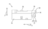
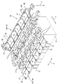
- FIG. 1 is an overall perspective view showing a battery module to which a battery wiring module according to an embodiment of the present invention is attached.
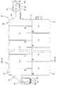
- FIG. 2 is a plan view showing a state in which the cover, the first end cover, and the second end cover of the battery module are opened.
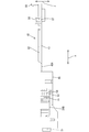
- FIG. 3 is a plan view showing the connecting unit.
- FIG. 4 is a rear view showing the connecting unit.
- FIG. 5 is a front view showing the connecting unit.
- FIG. 6 is a side view showing the connecting unit.
- 7 is a cross-sectional view taken along line VII-VII in FIG.
- FIG. 8 is an enlarged plan view of a main part showing a locking structure between the cover engaging portion and the cover engaging receiving portion.
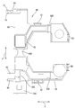
- FIG. 9 is a plan view showing the first end connecting unit.
- FIG. 10 is a front view showing the first end connecting unit.
- FIG. 11 is a side view showing the first end connecting unit.
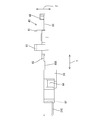
- FIG. 12 is a plan view showing the second end connecting unit.
- FIG. 13 is a front view showing the second end connecting unit.
- FIG. 14 is a side view showing the second end connecting unit.
- FIG. 15 is a rear view showing the second end connecting unit.
- FIG. 16 is a plan view showing a connecting battery wiring module.
- FIG. 17 is a plan view showing a battery wiring module for external connection.
- FIG. 18 is a perspective view showing a state in which the battery wiring module is assembled to the unit cell group.
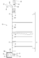
- FIG. 19 is a plan view showing a state in which the first end cover and the second end cover are opened by the sub hinge.
- FIG. 20 is a side view showing a state in which the first end cover and the second end cover are opened by the sub hinge.
- FIG. 21 is a plan view showing a state in which the first end cover and the second end cover are closed by the sub hinge.
- FIG. 22 is a side view showing a state in which the first end cover and the second end cover are closed by the sub hinge.
- the battery module 10 to which the battery wiring module 14 according to the present embodiment is attached is mounted on a vehicle (not shown) such as an electric vehicle or a hybrid vehicle, and is used as a power source for driving the vehicle.
- the battery module 10 includes a unit cell group 13 in which a plurality (twelve in the present embodiment) unit cells 12 each having an electrode terminal 11 are arranged side by side.
- the cell groups 13 are electrically connected by a battery wiring module 14.
- the direction indicated by the arrow X in FIG. Specifically, a direction toward the right front side in FIG. 1 is set to the right side, and a direction toward the left back side is set to the left side.
- the direction shown by the arrow line Y in FIG. 1 be the front-back direction.
- the direction toward the left front side in FIG. 1 is defined as the front, and the direction toward the right back side is defined as the rear.
- the direction shown by the arrow line Z in FIG. 1 be an up-down direction.
- the lower side in FIG. 1 is the lower side, and the upper side is the upper side.
- symbol may be attached
- the unit cell 12 has a flat rectangular parallelepiped shape.
- a power generation element (not shown) is accommodated inside the unit cell 12.
- a pair of electrode terminals 11, 11 are formed on the upper surface of the unit cell 12 so as to protrude upward at positions near both ends in the front-rear direction.
- One of the electrode terminals 11 is a positive terminal, and the other is a negative terminal.
- a screw thread is formed on the outer surface of the electrode terminal 11.
- the unit cells 12 are arranged so that the adjacent electrode terminals 11 have different polarities.
- the plurality of unit cells 12 are arranged in the left-right direction to form a unit cell group 13.
- the battery wiring module 14 arranged on the front side in FIG. 1 and connecting the adjacent single cells 12 is a connecting battery wiring module 14A, and the adjacent single cells 12 arranged on the back side in FIG.
- the battery wiring module 14 that connects and connects the cell group 13 to the power conductor 15 disposed in the vehicle is an external connection battery wiring module 14B.
- the connecting battery wiring module 14 ⁇ / b> A includes a plurality (six in this embodiment) of connecting units 16 connected in the left-right direction.
- the alignment direction of the connection units 16 is the same as the alignment direction of the cells 12 in the cell group 13.
- a connecting member 17 that connects the electrode terminals 11 of the adjacent unit cells 12 is attached to the connecting unit 16.
- the connecting member 17 is formed by pressing a metal plate made of copper, copper alloy, SUS, or the like into a predetermined shape.
- the connection member 17 has a rectangular shape extending in the left-right direction when viewed from above.
- the connection member 17 is formed with an electrode terminal through hole 18 ⁇ / b> A through which the electrode terminal 11 penetrates, through the connection member 17.
- the connecting unit 16 is formed with a synthetic resin accommodating portion 19 in which the connecting member 17 is accommodated.
- the accommodating portion 19 has a rectangular shape when viewed from above, and is slightly larger than the connecting member 17.
- An opening 20 ⁇ / b> A that opens upward is formed in the accommodating portion 19, and the connection member 17 is accommodated in the accommodating portion 19 from the opening 20 ⁇ / b> A.
- the electrode terminal 11 is electrically connected to the connection member 17 by screwing the nut 21 in a state of being penetrated into the electrode terminal through hole 18A of the connection member 17.
- the voltage detection terminal 22 is sandwiched between the nut 21 and the connection member 17 on one of the adjacent electrode terminals 11 connected by the connection member 17. Thereby, the voltage detection terminal 22 and the electrode terminal 11 are electrically connected.
- One end of a voltage detection line 23 is connected to the voltage detection terminal 22 by a known method such as crimping.
- the other end of the voltage detection line 23 is connected to an ECU (not shown).
- the connecting unit 16 is formed with a synthetic resin wire routing portion 24 ⁇ / b> A that accommodates the voltage detection wire 23 and is routed in the left-right direction.
- the electric wire routing portion 24A has a substantially groove shape when viewed from the left-right direction, and can accommodate the voltage detection line 23. 24 A of electric wire routing parts and the accommodating part 19 are connected (connected) by the connection part 25A made from a synthetic resin.
- the connecting portion 25A has a groove shape including a plate-like bottom portion 71 and a pair of groove walls 72A and 72B provided on the left and right sides of the bottom portion 71, and voltage detection connected to the voltage detection terminal 22 at the bottom portion 71.
- the terminal part of the line 23 is arranged.
- a pair of claw portions 73 protrudes inward from the upper ends of the pair of groove walls 72A and 72B, and the voltage detection line 23 can be held in the connecting portion 25 by the pair of claw portions 73.
- a cover 27 made of synthetic resin is integrally formed in the accommodating portion 19 through a hinge 26 from the side surface opposite to the connecting portion 25A.
- the cover 27 is rotatable about the hinge 26.
- the cover 27 has a substantially rectangular shape when viewed from above.
- the cover 27 is set to a size that can cover the accommodating portion 19, the connecting portion 25 ⁇ / b> A, and the electric wire routing portion 24 ⁇ / b> A.
- the cover 27 is elastically engaged with a cover lock portion 28 formed on the cover 27 and a cover lock receiving portion 29 formed on the electric wire routing portion 24, so that the accommodating portion 19, the connecting portion 25 ⁇ / b> A, It is held in a state of covering the electric wire routing portion 24A.
- the cover 27 is formed with ribs 30 projecting toward the accommodating portion 19 on the surface located on the accommodating portion 19 side in a state where the cover 27 is closed.
- the rib 30 is formed in a closed loop shape having a substantially rectangular shape.
- the rib 30 is formed so as to enter the housing portion 19 with the cover 27 closed. Specifically, it is formed in a shape slightly smaller than the lip of the opening 20 ⁇ / b> A of the housing portion 19.
- a locking portion 31 protruding outward is formed at the left end portion (corresponding to the locking end portion) of the connecting unit 16 (in the connecting portion 25A).
- the locking portion 31 protrudes downward at the tip of the plate-like bending piece 31 ⁇ / b> A and the bending piece 31 ⁇ / b> A and is locked to the hole edge portion of the first engagement hole 34. It consists of a protrusion 32.
- the above-mentioned downward is a direction orthogonal to the connection direction and means a direction orthogonal to the connection direction of the connection member 17.
- the bending piece 31 ⁇ / b> A is curved upward on the base end portion 31 ⁇ / b> B side, and the base end portion 31 ⁇ / b> B is integrated with the upper end portion of the groove wall 72 ⁇ / b> A of the connecting portion 25.
- the locking protrusion 32 protrudes downward in a step shape, and has a shape in which the protrusion dimension decreases in an inclined manner toward the distal end side.
- a locking receiving portion 33 that is locked to the locking portion 31 is formed at the right end portion (corresponding to the opening end portion) of the connecting unit 16.
- the latch receiving portion 33 is formed in a U shape with an upper surface opened, and the first engagement hole 34 provided in the latch receiving portion 33 penetrates in the left-right direction.
- the locking protrusion 32 penetrates through the inside of the first engagement hole 34 to the hole edge of the first engagement hole 34 (the end in the connecting direction of the locking receiving portion 33).
- the stepped portion of the locking protrusion 32 comes into contact.
- a predetermined clearance 35 ⁇ / b> A is formed between the locking receiving portion 33 (first engagement hole 34) and the locking projection 32.
- the predetermined clearance 35A is a clearance formed between the engagement hole and the locking protrusion when a locking structure in which the locking protrusion is generally locked to the hole edge of the engagement hole is adopted.
- the clearance 35A formed between the hole edge of the first engagement hole 34 and the locking projection 32 is 0.2 mm.
- the dimension range of the clearance 35A can be arbitrarily set as necessary.
- the variation regulating piece 36 has a flat plate shape in the front-rear direction (the direction indicated by the arrow Y in FIG. 3). In other words, the variation regulating piece 36 has a shape with a large thickness (thickness) in the vertical direction. Thereby, the direction (front-rear direction) in which the locking portion 31 is made thick and the direction (up-down direction) in which the variation regulating piece 36 is made thick have a perpendicular relationship.
- the front end of the variation regulating piece 36 is substantially the same position as the front end of the locking portion 31 in the connecting direction.
- the right end portion (corresponding to the opening end portion) of the connecting unit 16 is connected to the accommodating portion 19 and the wire routing portion 24, and the connected portion includes a left-right direction.
- a second engagement hole 37 with which the variation regulating piece 36 inserted in (the connection direction of the connection unit 16) is engaged is provided side by side with the first engagement hole 34.
- the second engagement hole 37 is a through-hole penetrating in the left-right direction through which the variation regulating piece 36 can be inserted.
- the rotation (with a predetermined value or more) about the front end side of the locking portion 31 is restricted between the movement restriction pieces 36 and the fluctuation restriction piece 36 and the second relation within a range in which this rotation (fluctuation) can be restricted.
- a clearance with the joint hole 37 is set.
- a cover engaging portion 38 that protrudes outward is formed at the left end portion of the cover 27 (one of the left and right side edges).
- the cover engaging portion 38 is formed by being divided into two forks, and at each tip portion, a cover engaging claw 39 is formed so as to protrude outward in the front-rear direction (direction indicated by arrow Y in FIG. 3). ing.
- a cover engagement receiving portion 40 that engages with the cover engagement portion 38 is formed on the side edge opposite to the side edge where the cover engagement portion 38 is formed.
- a cover engagement hole 41 through which the cover engagement claw 39 is penetrated is formed in the cover engagement receiving portion 40 so as to penetrate in the left-right direction.
- the cover engagement claw 39 penetrates the inside of the cover engagement hole 41 and penetrates the cover engagement hole 41 at the hole edge of the cover engagement hole 41. It comes in contact with the front side of the direction.
- a predetermined clearance 35 ⁇ / b> B is formed between the cover engagement hole 41 and the cover engagement claw 39.
- the predetermined clearance 35B generally refers to a clearance formed between the engagement hole and the engagement claw when a locking structure in which the engagement claw is locked to the hole edge of the engagement hole is employed. . This is because if the clearance 35B is not formed, there may occur a case where the engaging claw cannot be locked to the hole edge portion of the engaging hole even by a slight dimensional error.
- the clearance 35B formed between the hole edge of the cover engagement hole 41 and the cover 27 locking claw is 0.2 mm. The dimension range of the clearance 35B can be arbitrarily set as necessary.
- the connecting battery wiring module 14 ⁇ / b> A includes a locking portion 31, a first engaging hole 34 (locking receiving portion 33), a variation regulating piece 36, a second engaging hole 37, and a cover engaging portion. 38 and the cover engagement receiving part 40 engage, and the connection unit 16 is connected and formed in the left-right direction.
- the external connection battery wiring module 14 ⁇ / b> B arranged on the rear side includes a plurality of (in this embodiment, five) connection units 16 connected in the left-right direction and the left end portions of the plurality of connection units 16 connected.
- a first end connection unit 42 connected to the right end of the plurality of connection units 16 connected to the second end connection unit 43.
- the arrangement direction of the first end connection unit 42, the connection unit 16, and the second end connection unit 43 is the same as the arrangement direction of the cells 12 in the cell group 13.
- the first end connection unit 42 includes the electrode terminal 11 on the rear side of the unit cell 12 located at the left end of the unit cell group 13 and the power conductor 15 disposed in the vehicle. It has the 1st end part connection member 44 to connect.
- the first end connection member 44 is formed by pressing a metal plate made of copper, copper alloy, SUS, or the like into a predetermined shape.
- the first end connection member 44 has a bent shape elongated in the vertical direction when viewed from above.
- An electrode terminal through hole 18B through which the electrode terminal 11 passes is formed at the rear end portion of the first end connection member 44, and a bolt (not shown) is passed through the front end portion of the first end connection member 44.
- a bolt through hole 45A is formed.
- the first end connecting member 44 and the power conductor 15 are sandwiched between the bolt head and the nut by screwing a bolt inserted into the bolt through hole 45A into a nut (not shown). Fixed in state.
- the first end connecting unit 42 is formed with a first end connecting member accommodating portion 46 made of synthetic resin in which the first end connecting member 44 is accommodated.
- the first end connection member accommodating portion 46 has a shape that follows the first end connection member 44 as viewed from above, and has a slightly larger shape.
- An opening 20B that opens upward is formed in the first end connecting member accommodating portion 46, and the first end connecting member 44 is accommodated in the first end connecting member accommodating portion 46 from the opening 20B. It has come to be.
- the electrode terminal 11 is electrically connected to the first end connection member 44 by screwing the nut 21 in a state of being penetrated into the electrode terminal through hole 18B of the first end connection member 44.
- the voltage detection terminal 22 is sandwiched between the nut 21 and the first end connection member 44. Thereby, the voltage detection terminal 22 and the electrode terminal 11 are electrically connected.
- One end of a voltage detection line 23 is connected to the voltage detection terminal 22 by a known method such as crimping.
- the other end of the voltage detection line 23 is connected to an ECU (not shown).
- the first end connection unit 42 is formed with a synthetic resin wire routing portion 24B that accommodates the voltage detection wire 23 and is wired in the left-right direction.
- the electric wire routing portion 24B has a generally groove shape when viewed from the left-right direction, and can accommodate the voltage detection line 23.
- the electric wire routing portion 24B and the first end connection member accommodation portion 46 are connected by a connecting portion 25B made of synthetic resin.
- the voltage detection terminal 22 is held in the connecting portion 25B.
- a first end cover 47 made of synthetic resin is integrally formed on the first end connection member accommodating portion 46 from the side surface opposite to the connecting portion 25B via a main hinge 48A.
- the first end cover 47 is rotatable about the main hinge 48A.
- the first end cover 47 generally has a shape that follows the first end connection member accommodating portion 46, the connecting portion 25B, and the electric wire routing portion 24B as viewed from above.
- the first end cover 47 is set to a size that can cover the first end connection member accommodating portion 46, the connecting portion 25B, and the wire routing portion 24B.
- the first end cover 47 is further formed with a sub hinge 49A.
- the first end cover 47 is formed to be rotatable around the sub hinge 49A.
- this sub hinge 49A a portion of the first end cover 47 corresponding to a region where the first end connection member 44 and the power conductor 15 are connected can be opened and closed.
- the first end cover 47 includes a first end cover lock portion 50 formed in the first end cover 47 and a first end portion formed in the first end connection member accommodating portion 46.
- the first end connection member accommodating portion 46, the connecting portion 25B, and the electric wire routing portion 24B are held in a covered state. Yes.
- the first end cover 47 is connected to the first end cover 47 on the surface located on the first end connection member accommodating portion 46 side in a state where the first end cover 47 is closed.
- a first end-side rib 52 that protrudes toward the member accommodating portion 46 is formed.
- the first end side rib 52 is formed so as to enter the first end connection member accommodating portion 46 in a state where the first end cover 47 is closed.
- a first end lock receiving portion 53 that engages with a lock 31 formed on the connection unit 16 disposed on the right side of the first end connection unit 42. Is formed.
- the first end locking receiving portion 53 is formed with a first end first engaging hole 54 through which the locking protrusion 32 penetrates in the left-right direction. ing.
- the engaging structure between the engaging portion 31 and the first end portion engaging receiving portion 53 (first end first engaging hole 54) is the same as the engaging portion 31 and the engaging receiving portion 33 (shown in FIG. 7). Since it is substantially the same as the engagement structure with the first engagement hole 34), a duplicate description is omitted.
- the fluctuation regulating piece 36 formed on the connection unit 16 disposed on the right side of the first end connection unit 42 is engaged with the right edge of the first end connection unit 42.
- a first end second engagement hole 55 is formed.
- the first end second engagement hole 55 is a through-hole penetrating in the left-right direction through which the variation regulating piece 36 can penetrate.
- first end cover 47 As shown in FIGS. 9 and 11, on the right edge of the first end cover 47, a cover engaging portion 38 formed on the cover 27 of the connecting unit 16 located on the right side of the first end connecting unit 42, A first end cover engagement receiving portion 56 to be engaged is formed.
- the first end cover engagement receiving portion 56 is formed with a first end cover engagement hole 57 through which the cover engagement claw 39 penetrates in the left-right direction.
- the engagement structure between the cover engaging portion 38 and the first end cover engagement receiving portion 56 is substantially the same as the engagement structure between the cover engaging portion 38 and the cover engagement receiving portion 40 shown in FIG. Since they are the same, redundant description is omitted.
- the first end connecting unit 42 is connected to the left end of the connected multi-unit connecting unit 16. Specifically, the configuration in which the locking portion 31 and the first end portion locking receiving portion 53 are engaged, and the configuration in which the cover engaging portion 38 and the first end cover engaging receiving portion 56 are engaged, The first end connecting unit 42 and the connecting unit 16 are connected.
- the second end connection unit 43 includes a rear electrode terminal 11 of the unit cell 12 located at the right end of the unit cell group 13, a power conductor 15 disposed in the vehicle,
- the second end connection member 58 is connected.
- the second end connection member 58 is formed by pressing a metal plate made of copper, copper alloy, SUS or the like into a predetermined shape.
- the second end connection member 58 has a bent shape elongated in the left-right direction when viewed from above.
- An electrode terminal through-hole 18C through which the electrode terminal 11 passes is formed at the left end of the second end connection member 58, and a bolt (not shown) is passed through at the right end of the second end connection member 58.
- a through hole 45B is formed.
- the second end connecting member 58 and the power conductor 15 are sandwiched between the bolt head and the nut by screwing a bolt inserted into the bolt through hole 45B into a nut (not shown). Fixed in state.
- the second end connecting unit 43 is formed with a second end connecting member housing 59 made of synthetic resin in which the second end connecting member 58 is housed.
- the second end connection member accommodating portion 59 has a shape following the first end connection member 44 as viewed from above, and has a slightly larger shape.
- the second end connecting member accommodating portion 59 is formed with an opening 20C that opens upward, and the second end connecting member 58 is accommodated in the second end connecting member accommodating portion 59 from the opening 20C. It has come to be.
- the electrode terminal 11 is electrically connected to the second end connection member 58 by screwing the nut 21 in a state of being penetrated into the electrode terminal through hole 18C of the second end connection member 58.
- the voltage detection terminal 22 is sandwiched between the nut 21 and the second end connection member 58 in the electrode terminal 11. Thereby, the voltage detection terminal 22 and the electrode terminal 11 are electrically connected.
- One end of a voltage detection line 23 is connected to the voltage detection terminal 22 by a known method such as crimping.
- the other end of the voltage detection line 23 is connected to an ECU (not shown).
- the second end connecting unit 43 is formed with a synthetic resin electric wire routing portion 24 ⁇ / b> C that accommodates the voltage detection wire 23 and is routed in the left-right direction.
- the electric cable routing portion 24 ⁇ / b> C has a generally groove shape when viewed from the left-right direction, and can accommodate the voltage detection wire 23.
- 24 C of electric wire routing parts and the 2nd end part connection member accommodating part 59 are connected by the connection part 25C made from a synthetic resin.
- the voltage detection terminal 22 is held at the connecting portion 25C.
- a second end cover 60 made of synthetic resin is integrally formed on the second end connection member accommodating portion 59 from the side surface opposite to the coupling portion 25C via the main hinge 48B.
- the second end cover 60 is rotatable about the main hinge 48B.
- the second end cover 60 generally has a shape that follows the second end connection member accommodating portion 59, the connecting portion 25C, and the wire routing portion 24C as viewed from above.
- the 2nd end part cover 60 is set to the magnitude
- the second end cover 60 includes a second end cover lock part 61 formed on the second end cover 60 and a second end cover member accommodating part 59.
- the end cover lock receiving portion 62 By being elastically engaged with the end cover lock receiving portion 62, the second end connection member accommodating portion 59, the connecting portion 25C, and the wire routing portion 24C are held in a covered state. It has become.
- the second end cover 60 is further formed with a sub hinge 49B as shown in FIG.
- the second end cover 60 is formed to be rotatable around the sub hinge 49B.
- this sub hinge 49 ⁇ / b> B a portion of the second end cover 60 corresponding to a region where the second end connection member 58 and the power conductor 15 are connected can be opened and closed.
- the second end cover 60 includes a second end cover sub-lock portion 63 formed on the second end cover 60 and a second end cover member receiving portion 59 formed on the second end cover member receiving portion 59.
- the second end cover 60 protrudes toward the second end connection member accommodating portion 59 on the surface located on the second end connection member accommodating portion 59 side with the second end cover 60 closed.
- a second end portion side rib 65 is formed.
- the second end portion side rib 65 is formed so as to enter the accommodating portion 19 in a state in which the second end portion cover 60 is closed.
- the second end connecting unit 43 has a left edge that engages with a latch receiving portion 33 formed on the connecting unit 16 disposed on the left side of the second end connecting unit 43.
- a two-end locking portion 66 is formed.
- the second end locking portion 66 is formed to protrude to the left.
- a second end unit engaging claw 67 protruding downward is formed at the tip of the second end locking portion 66.
- the engagement structure between the second end locking portion 66 and the locking receiving portion 33 (first locking hole 34) is the same as the locking portion 31 and the locking receiving portion 33 (first locking shown in FIG. 7). Since it is substantially the same as the engagement structure with the hole 34), redundant description is omitted.
- a variation regulating piece 68 is formed. As shown in FIGS. 12 and 13, the second end variation regulating piece 68 has a flat plate shape in the front-rear direction (the direction indicated by the arrow Y in FIG. 12).
- the second end variation restricting piece 68 is configured to penetrate through the second engagement hole 37 formed in the connection unit 16 disposed on the left side of the second end connection unit 43.
- a second end cover engaging portion 69 protruding leftward is formed on the left edge of the second end cover 60.
- the second end cover engaging portion 69 is formed to be divided into two forks, and the second end cover engaging claws 70 are arranged in the front-rear direction (the direction indicated by the arrow Y in FIG. 12) at each tip portion. Each of them protrudes outward.
- the second end cover engaging portion 69 is adapted to engage with the cover engagement receiving portion 40 of the cover 27 formed on the connecting unit 16 disposed on the left side of the second end connecting unit 43.
- the engagement structure between the second end cover engagement portion 69 and the cover engagement receiving portion 40 is substantially the same as the engagement structure between the cover engagement portion 38 and the cover engagement receiving portion 40 shown in FIG. Since they are the same, redundant description is omitted.
- the second end connecting unit 43 is connected to the right end of the connected multi-unit connecting unit 16. Specifically, the configuration in which the second end locking portion 66 and the locking receiving portion 33 (first engaging hole 34) are engaged, and the second end cover engaging portion 69 and the cover engaging receiving portion 40 are engaged.
- the second end connecting unit 43 and the connecting unit 16 are connected to each other by the configuration in which they are engaged with each other.
- connection units 16 are prepared, and the engagement portions 31 of one connection unit 16 and the engagement receiving portions 33 of the other connection units 16 are sequentially engaged from the left and right directions.
- the cover engaging portion 38 and the cover engaging receiving portion 40 of the other connecting unit 16 are sequentially engaged from the left and right directions.
- the five connection units 16 are connected in the left-right direction.
- the locking portion 31 is locked to the hole edge portion of the first engagement hole 34, and the variation restricting piece 36 is fitted into the second engagement hole 37, so that the direction other than the connecting direction between the two units 16 is exceeded. Since relative movement is restricted, rotation (fluctuation) about the front end side of the locking portion 31 is released so that locking of the locking portion 31 to the edge of the first engagement hole 34 is released. Therefore, the connection units 16 are relatively firmly connected to each other.
- the voltage detection terminal 22 is crimped to one end of the voltage detection line 23, and the voltage detection line 23 and the voltage detection terminal 22 are connected.
- the voltage detection line 23 is routed to the wire routing portion 24A of the connected connection unit 16, each voltage detection terminal 22 is held in each connection portion 25A, and each voltage detection terminal 22 is disposed in each accommodation portion 19. To do. Thereby, as shown in FIG. 16, the connection battery wiring module 14A is completed.
- one first end connecting unit 42, five connecting units 16, and one second end connecting unit 43 are prepared. While engaging the 1st edge part latching receiving part 53 of the 1st edge part connection unit 42 and the engaging part of the connection unit 16 from the left-right direction, it is 1st edge part cover engagement of the 1st edge part connection unit 42.
- the receiving part 56 and the cover engaging part 38 of the connection unit 16 are engaged from the left-right direction.
- the engaging portion 31 of one connecting unit 16 and the engaging receiving portion 33 (first engaging hole 34) of the other connecting unit 16 are engaged from the left and right directions, and the cover member of the one connecting unit 16 is engaged.
- the joining portion 38 and the cover engagement receiving portion 40 of the other connecting unit 16 are engaged from the left and right directions.
- connection unit 16 and the second end portion engagement portion 66 of the second end connection unit 43 are engaged from the left and right directions, and the cover engagement reception portion 40 of the connection unit 16 is engaged.
- the second cover engaging unit 38 of the second end connecting unit 43 is engaged from the left and right directions.
- first end connection member 44 is accommodated inside the first end connection member accommodation portion 46 of the first end connection unit 42.
- the connecting member 17 is accommodated in the accommodating portion 19 of each coupling unit 16.
- the second end connection member 58 is accommodated inside the second end connection member accommodation portion 59 of the second end connection unit 43.
- the voltage detection terminal 22 is crimped to one end of the voltage detection line 23, and the voltage detection line 23 and the voltage detection terminal 22 are connected.
- the voltage detection line 23 is routed to the wire routing portions 24A, 24B, and 24C of the connected first end connection unit 42, connection unit 16, and second end connection unit 43, and the connection portions 25A and 25B. 25C, the respective voltage detection terminals 22 are held, and the respective voltage detection terminals 22 are arranged inside the first end connection member accommodation portion 46, the accommodation portion 19, and the second end connection member accommodation portion 59, respectively.
- the external connection battery wiring module 14B is completed.
- the connecting battery wiring module 14 ⁇ / b> A is attached to the electrode terminal 11 located on the front side of the cell group 13 from above. At this time, the electrode terminal 11 is made to penetrate through the electrode terminal through holes 18A, 18B, 18C of the connection member 17.
- the external connection battery wiring module 14B is attached to the electrode terminal 11 located on the back side of the cell group 13 from above.
- the electrode terminal 11 passes through the electrode terminal through hole 18B of the first end connection member 44, the electrode terminal through hole 18A of the connection member 17, and the electrode terminal through hole 18C of the second end connection member 58. (See FIG. 18).
- each electrode terminal 11 Thereafter, a nut 21 is screwed into each electrode terminal 11. Thereby, as shown in FIG. 2, twelve unit cells 12 are connected in series.
- the plurality of connected covers 27 are rotated about the hinge 26 and closed so as to cover the accommodating portion 19, the connecting portion 25A, and the electric wire routing portion 24A.
- the cover lock portion 28 and the cover lock receiving portion 29 are elastically engaged, whereby the cover 27 is held in a closed state.
- the connected first end cover 47, the plurality of covers 27, and the second end cover 60 are rotated around the main hinges 48A, 48B and the hinge 26. It closes so that the accommodating part 19, connecting part 25A, 25B, 25C, and electric wire routing part 24A, 24B, 24C may be covered.
- the cover lock portion 28 and the cover lock receiving portion 29 are elastically engaged, and the second end cover lock portion 61 and the second end formed in the second end connection member accommodating portion 59 are also provided.
- the first end cover 47, the plurality of covers 27, and the second end cover 60 that are connected are held in a closed state by elastically engaging with the part cover lock receiving part 62.
- the region corresponding to the portion where the part connecting member 58 and the external conductor are connected can be opened and closed around the sub hinge 49 (see FIGS. 19 and 20).
- the power conductor 15 disposed in the vehicle and the first end connecting member 44 are connected by bolting. Further, the power conductor 15 and the second end connection member 58 are connected by bolting. Thereafter, the first end cover 47 is rotated around the sub hinge 49A, and the first end cover lock portion 50 and the first end cover lock receiving portion 51 are elastically engaged. As a result, the first end cover 47 is held in a state of covering the first end connection member accommodating portion 46. Further, the second end cover 60 is rotated about the sub hinge 49B, and the second end cover sub lock portion 63 and the second end cover sub lock receiving portion 64 are elastically engaged. Thereby, the 2nd end part cover 60 is hold
- a battery wiring module 14 attached to a unit cell group 13 in which a plurality of unit cells 12 having positive and negative electrode terminals 11 are arranged, and a plurality of units electrically connecting the electrode terminals 11 of adjacent unit cells 12.
- a plurality of connecting units 16 that hold the connecting member 17, an opening end portion that is located on one side of the connecting unit 16 in the connecting direction and has a first engagement hole 34 that opens in the connecting direction; It is located on the other side of the connecting direction in the connecting unit 16, and is inserted into the first engaging hole 34 of the connecting unit 16 located adjacent to the connecting direction and locked to the hole edge of the first engaging hole 34.
- the variation regulating piece 36 has an opening end portion. And provided at the other end of the locking end in the connecting direction. It is inserted through the second engagement hole 37, the coupling unit 16 adjacent to regulate the varying to the connecting direction (insertion direction) different from directions.
- the locking portion 31 is locked to the hole edge portion of the first engagement hole 34 that opens in the connecting direction of the connecting unit 16, it is possible to reliably connect the connecting units 16. It becomes.
- the locking portion 31 when the locking portion 31 is only locked in the first engagement hole 34, for example, when one unit rotates around the distal end side of the locking portion 31, the locking of the locking portion 31 is released.
- the variation regulating piece 36 in addition to the locking portion 31, the variation regulating piece 36 is inserted into the second engagement hole 37 to regulate variation in a direction different from the coupling direction.
- the locking portion 31 includes a plate-like bending piece 31A, and a locking protrusion that protrudes to the side orthogonal to the connecting direction on the distal end side of the bending piece 31A and is locked to the hole edge portion of the first engagement hole 34. 32. If it does in this way, it will become possible to lock the latching
- the fluctuation regulating piece 36 has a thick shape in the thickness direction of the bending piece 31A. If it does in this way, it will become possible to regulate rotation centering on the tip side of locking part 31 of connecting unit 16 certainly with simple composition.
- the present invention is not limited to the embodiments described with reference to the above description and drawings.
- the following embodiments are also included in the technical scope of the present invention.
- the first engagement hole 34 and the second engagement hole 37 are provided on the right end side (one side in the connection direction, the open end) of the connection unit 16,
- the variation restricting piece 36 is provided on the left end side (the other side in the connecting direction, the engaging end portion) of the connecting unit 16, but is not limited to this, and the engaging portion 31 and the variation restricting piece 36 (the first one)
- the first engagement hole 34 and the second engagement hole 37) may be provided on different sides of the connection unit 16 in the connection direction.
- first engagement hole 34 and the variation regulating piece 36 are provided on one side (opening end side) in the connection direction of the connection unit 16, and the second engagement hole 37 and the locking portion 31 are provided. You may make it provide in the other side (locking edge part side) in the connection direction of the connection unit 16.
- connecting units 16 are connected.
- the present invention is not limited to this, and two to four, or seven or more, any, as required
- the number of connecting units 16 may be connected.
- First end connecting member accommodating portion 47 ... first end cover 48A, 48B ... main hinge 49A, 49B ... sub hinge 52 ... first end side rib 53 ... first 1 end locking receiving portion 54 ... first end first engaging hole 56 ... first end cover engaging receiving portion 57 ... first end cover engaging hole 58 ... first 2 end connection member 59 ... 2nd end connection member accommodating part 60 ... 2nd end cover 65 ... 2nd edge part side rib 66. .. Second end locking portion 67 ... Second end unit engaging claw 69 ... Second end cover engaging portion 70 ... Second end cover engaging claw 71 ... Bottom 72A, 72B ... groove wall
Abstract
電池配線モジュール14は、隣り合う単電池12の電極端子11間を電気的に接続する複数の接続部材17を保持する複数の連結ユニット16と、連結ユニット16のうち連結方向の一方の側に位置して、連結方向に開口する第1係合孔34が形成された開口端部と、連結ユニット16のうち連結方向の他方の側に位置して、連結方向について隣に位置する連結ユニット16の第1係合孔34に挿通されて第1係合孔34の孔縁部に係止される係止部31が形成された係止端部と、開口端部及び係止端部のいずれか一方に設けられた変動規制片36と、を備え、変動規制片36は、開口端部及び係止端部の他方に連結方向に開口して設けられた第2係合孔37に挿通されて、隣り合う連結ユニット16が連結方向と異なる方向へ変動することを規制する。
Description
本発明は、単電池群に取り付けられる電池配線モジュールに関する。
電気自動車やハイブリッド車用の電池モジュールは、正極及び負極の電極端子を有する複数個の単電池が並んで配列されており、隣り合う単電池の電極端子間が接続部材(バスバー)で接続されることにより複数の単電池が直列や並列に接続されるようになっている(特許文献1参照)。
ここで、接続部材の取付作業を簡素化等するために、特許文献2に示すように、複数の樹脂製の接続ユニットに接続部材を収容し、これら接続ユニット同士を連結した電池配線モジュール(電池接続アセンブリ)を複数の単電池に一体的に装着することが考えられた。
この特許文献2では、各接続ユニットの並び方向の一方の側に設けられた係合部と、各接続ユニットの並び方向の他方の側に設けられた被係合部との係合により各接続ユニットが連結されるようになっている。
ところで、特許文献2の構成は、接続ユニットの並び方向における一端側に係合部の係止孔を設け、U字状に湾曲した係止片を上方から係止孔に貫通させて係止させるようになっている。しかしながら、U字状に湾曲した係止片を係止孔の孔縁部に係止させてユニット間を連結する場合には、連結の強度が弱くなりやすいという問題があった。
本発明は上記のような事情に基づいて完成されたものであって、確実にユニット間を連結することが可能な電池配線モジュールを提供することを目的とする。
本発明に係る電池配線モジュールは、正極及び負極の電極端子を有する単電池が複数個並べられた単電池群に取付けられる電池配線モジュールであって、隣り合う前記単電池の電極端子間を電気的に接続する接続部材を保持すると共に、連結方向に連結される複数の連結ユニットと、前記連結ユニットのうち前記連結方向の一方の側に位置して、前記連結方向に開口する第1係合孔が形成された開口端部と、前記連結ユニットのうち前記連結方向の他方の側に位置して、前記連結方向について隣に位置する前記連結ユニットの前記第1係合孔に挿通されて前記第1係合孔の孔縁部に係止される係止部が形成された係止端部と、前記開口端部及び前記係止端部のいずれか一方に設けられた変動規制片と、を備え、前記変動規制片は、前記開口端部及び前記係止端部の他方に前記連結方向に開口して設けられた第2係合孔に挿通されて、隣り合う前記連結ユニットが前記連結方向と異なる方向へ変動することを規制するものである。
本構成によれば、係止部が連結ユニットの連結方向に開口する第1係合孔に係止されるため、確実に連結ユニット間を連結することが可能となる。
ここで、係止部が第1係合孔に係止されるのみでは、例えば一方の連結ユニットが係止部の先端側を軸として回転した場合に係止部の係止が解除されるおそれがあるが、本構成では、係止部の他に、変動規制片が第2係合孔に挿通されて前記連結方向と異なる方向への変動を規制するようになっているため、連結ユニットの係止部の先端側を軸とした回転(変動)を抑制することが可能となる。よって、簡易な構成で係止部の係止が解除されることを防止することができる。
上記構成に加えて以下の構成を有すればより好ましい。
前記係止部は、板状の撓み片と、前記撓み片の先端側にて前記連結方向と直交する側に突出して前記第1係合孔の孔縁部に係止される係止突部とを備える。
前記係止部は、板状の撓み片と、前記撓み片の先端側にて前記連結方向と直交する側に突出して前記第1係合孔の孔縁部に係止される係止突部とを備える。
このようにすれば、簡素な構成で、係止部を第1係合孔の孔縁部に係止させることが可能になる。
前記変動規制片は、前記撓み片の厚み方向に肉厚の形状をなす。
このようにすれば、簡素な構成で確実に連結ユニットの係止部の先端側を軸とした回転を規制することが可能となる。
本発明によれば、電池配線モジュールについて簡素な構成でユニット間を連結することが可能となる。
<実施形態1>
本発明の一実施形態を図1ないし図22を参照しつつ説明する。本実施形態に係る電池配線モジュール14が取り付けられた電池モジュール10は、電気自動車又はハイブリッド自動車等の車両(図示せず)に搭載されて、車両を駆動するための電源として使用される。
本発明の一実施形態を図1ないし図22を参照しつつ説明する。本実施形態に係る電池配線モジュール14が取り付けられた電池モジュール10は、電気自動車又はハイブリッド自動車等の車両(図示せず)に搭載されて、車両を駆動するための電源として使用される。
電池モジュール10は、電極端子11を備えた複数(本実施形態では12個)の単電池12が並べて配された単電池群13を有する。単電池群13は、電池配線モジュール14によって電気的に接続されている。
なお、以下の説明では、図1における矢線Xで示された方向を左右方向とする。詳細には、図1における右手前側に向かう方向を右方とし、左奥側に向かう方向を左方とする。また、図1における矢線Yで示された方向を前後方向とする。詳細には、図1における左手前側に向かう方向を前方とし、右奥側に向かう方向を後方とする。また、図1における矢線Zで示された方向を上下方向とする。詳細には、図1における下方を下方とし、上方を上方とする。また、以下の説明において、複数の同一部材については、一つの部材に符号を付し、他の部材については符号を省略することがある。
(単電池12)
単電池12は扁平な直方体形状をなしている。単電池12の内部には図示しない発電要素が収容されている。単電池12の上面には、前後方向の両端部寄りの位置に、一対の電極端子11,11が上方に突出して形成されている。電極端子11の一方は正極端子であり、他方は負極端子である。電極端子11の外面にはねじ山が形成されている。単電池12は、隣り合う電極端子11が異なる極性となるように配置されている。複数の単電池12は左右方向に並べられて単電池群13を構成している。
単電池12は扁平な直方体形状をなしている。単電池12の内部には図示しない発電要素が収容されている。単電池12の上面には、前後方向の両端部寄りの位置に、一対の電極端子11,11が上方に突出して形成されている。電極端子11の一方は正極端子であり、他方は負極端子である。電極端子11の外面にはねじ山が形成されている。単電池12は、隣り合う電極端子11が異なる極性となるように配置されている。複数の単電池12は左右方向に並べられて単電池群13を構成している。
(電池配線モジュール14)
図1における前側に配されて、隣り合う単電池12同士を接続する電池配線モジュール14は連結用電池配線モジュール14Aとされており、図1における後ろ側に配されて隣り合う単電池12同士を接続すると共に単電池群13を車両に配された電力導体15と接続する電池配線モジュール14は外部接続用電池配線モジュール14Bとされている。電力導体15としては、電線、バスバー等、必要に応じて任意の導体を用いることができる。
図1における前側に配されて、隣り合う単電池12同士を接続する電池配線モジュール14は連結用電池配線モジュール14Aとされており、図1における後ろ側に配されて隣り合う単電池12同士を接続すると共に単電池群13を車両に配された電力導体15と接続する電池配線モジュール14は外部接続用電池配線モジュール14Bとされている。電力導体15としては、電線、バスバー等、必要に応じて任意の導体を用いることができる。
(連結用電池配線モジュール14A)
図2に示すように、連結用電池配線モジュール14Aは、左右方向に連結された複数(本実施形態では6つ)の連結ユニット16を備える。連結ユニット16の並び方向は単電池群13における単電池12の並び方向と一致している。
図2に示すように、連結用電池配線モジュール14Aは、左右方向に連結された複数(本実施形態では6つ)の連結ユニット16を備える。連結ユニット16の並び方向は単電池群13における単電池12の並び方向と一致している。
(連結ユニット16)
連結ユニット16には、隣り合う単電池12の電極端子11間を接続する接続部材17が装着される。接続部材17は、銅、銅合金、SUS等からなる金属板材が所定の形状にプレス加工されてなる。接続部材17は上方から見て左右方向に延びる長方形状をなしている。接続部材17には、電極端子11が貫通される電極端子貫通孔18Aが、接続部材17を貫通して形成されている。
連結ユニット16には、隣り合う単電池12の電極端子11間を接続する接続部材17が装着される。接続部材17は、銅、銅合金、SUS等からなる金属板材が所定の形状にプレス加工されてなる。接続部材17は上方から見て左右方向に延びる長方形状をなしている。接続部材17には、電極端子11が貫通される電極端子貫通孔18Aが、接続部材17を貫通して形成されている。
連結ユニット16には、図3に示すように、接続部材17が収容される合成樹脂製の収容部19が形成されている。収容部19は上方から見て長方形状をなしており、接続部材17よりもやや大きな形状とされている。収容部19には上方に開口する開口部20Aが形成されており、この開口部20Aから接続部材17が収容部19内に収容されるようになっている。
電極端子11は、接続部材17の電極端子貫通孔18A内に貫通された状態でナット21が螺合されることにより、接続部材17と電気的に接続される。接続部材17によって接続される隣り合う電極端子11の一方には、ナット21と接続部材17の間に電圧検知端子22が挟まれている。これにより電圧検知端子22と電極端子11とが電気的に接続される。電圧検知端子22には電圧検知線23の一方の端部が圧着等の公知の手法により接続されている。電圧検知線23の他方の端部は図示しないECUに接続されている。
連結ユニット16には、図3に示すように、電圧検知線23が収容されて左右方向に配索される合成樹脂製の電線配索部24Aが形成されている。電線配索部24Aは左右方向から見て概ね溝状をなしており、電圧検知線23が収容可能になっている。電線配索部24Aと、収容部19とは、合成樹脂製の連結部25Aによって連結(接続)されている。
連結部25Aは、板状の底部71と底部71を挟んだ左右に設けられる一対の溝壁72A,72Bとからなる溝状をなしており、底部71に電圧検知端子22に接続される電圧検知線23の端末部が配される。一対の溝壁72A,72Bの上端部には、一対の爪部73が内方側に突出しており、この一対の爪部73により電圧検知線23を連結部25内に保持することができる。
収容部19には、連結部25Aと反対側の側面からヒンジ26を介して合成樹脂製のカバー27が一体に形成されている。カバー27は、ヒンジ26を中心として回動可能になっている。カバー27は上方から見て概ね長方形状をなしている。カバー27は、収容部19、連結部25A、及び電線配索部24Aを覆うことができる大きさに設定されている。カバー27は、カバー27に形成されたカバーロック部28と、電線配索部24に形成されたカバーロック受け部29とが弾性的に係合することにより、収容部19、連結部25A、及び電線配索部24Aを覆った状態で保持されるようになっている。
カバー27には、カバー27が閉じられた状態で収容部19側に位置する面に、収容部19側に突出するリブ30が形成されている。リブ30は、略長方形状をなす閉じたループ状形成されている。リブ30は、カバー27が閉じられた状態で収容部19内に入り込むように形成されている。詳細には、収容部19の開口部20Aの口縁よりもやや小さな形状に形成されている。
(連結ユニット16の係合構造)
連結ユニット16の(連結部25Aにおける)左端部(係止端部に相当)には、外方(連結方向)に突出する係止部31が形成されている。係止部31は、図4に示すように、板状の撓み片31Aと、撓み片31Aの先端部にて下方に突出して第1係合孔34の孔縁部に係止される係止突部32とからなる。なお、上記した下方とは、連結方向と直交する方向であって、接続部材17の接続方向と直交する方向を意味する。
連結ユニット16の(連結部25Aにおける)左端部(係止端部に相当)には、外方(連結方向)に突出する係止部31が形成されている。係止部31は、図4に示すように、板状の撓み片31Aと、撓み片31Aの先端部にて下方に突出して第1係合孔34の孔縁部に係止される係止突部32とからなる。なお、上記した下方とは、連結方向と直交する方向であって、接続部材17の接続方向と直交する方向を意味する。
撓み片31Aは、図7に示すように、その基端部31B側が上方に湾曲しており、この基端部31Bが連結部25の溝壁72Aの上端部と一体になっている。係止突部32は段差状に下方に突出し、先端側に向けて傾斜状に突出寸法が小さくなる形状をなす。
図3及び図6に示すように、連結ユニット16の右端部(開口端部に相当)には、係止部31に係止される係止受け部33が形成されている。係止受け部33は、上面側が開口するU字状に形成されており、この係止受け部33に設けられる第1係合孔34が左右方向に貫通する形状となっている。
図7に示すように、係止突部32は、第1係合孔34の内部を貫通して第1係合孔34の孔縁部(係止受け部33の連結方向の端部)に、係止突部32の段差部分が当接するようになっている。係止受け部33(第1係合孔34)と係止突部32との間には、所定のクリアランス35Aが形成されている。所定のクリアランス35Aとは、一般に係合孔の孔縁部に係止突部を係止するという係止構造を採用する場合に、係合孔と係止突部との間に形成されるクリアランスをいう。このクリアランス35Aが形成されていないと、僅かな寸法誤差によっても、係止突部が係合孔の孔縁部に係止できない場合が発生しうるからである。本実施形態においては、第1係合孔34の孔縁部と係止突部32との間に形成されたクリアランス35Aは0.2mmである。このクリアランス35Aの寸法範囲は、必要に応じて任意に設定しうる。
図3に示すように、連結ユニット16の左端部(係止端部に相当)には、係止部31と前後方向(図3における矢線Yの示す方向)に並んで外方(連結方向)に突出する変動規制片36が形成されている。図3及び図5に示すように、変動規制片36は前後方向(図3における矢線Yで示す方向)に扁平な板状をなしている。言い換えると、変動規制片36は、上下方向に厚み寸法の大きい(肉厚の)形状をなしている。これにより、係止部31の肉厚とされる方向(前後方向)と、変動規制片36の肉厚とされる方向(上下方向)とは直交する関係となっている。変動規制片36の先端は、係止部31の先端と連結方向にほぼ同じ位置とされている。
図3及び図6に示すように、連結ユニット16の右端部(開口端部に相当)は、収容部19と電線配策部24が連結されており、この連結された部分には、左右方向(連結ユニット16の連結方向)に挿通される変動規制片36が係合される第2係合孔37が第1係合孔34と前後に並んで設けられている。
第2係合孔37は、変動規制片36を挿通可能な、左右方向に貫通された貫通孔とされており、変動規制片36が挿通されると(嵌め入れられると)、隣り合う連結ユニット16の間で係止部31の先端側を軸とした(所定以上の)回転が規制されるようになっており、この回転(変動)を規制できる範囲で、変動規制片36と第2係合孔37との間のクリアランスが設定されている。
(カバー27の係合構造)
図3に示すように、カバー27の左端部(左右両側縁の一方)には、外方に突出するカバー係合部38が形成されている。カバー係合部38は、二股に分かれて形成されており、各先端部には、カバー係合爪39が前後方向(図3における矢線Yで示す方向)の外方にそれぞれ突出して形成されている。
図3に示すように、カバー27の左端部(左右両側縁の一方)には、外方に突出するカバー係合部38が形成されている。カバー係合部38は、二股に分かれて形成されており、各先端部には、カバー係合爪39が前後方向(図3における矢線Yで示す方向)の外方にそれぞれ突出して形成されている。
図3及び図6に示すように、カバー係合部38が形成された側縁と反対側の側縁には、カバー係合部38と係合するカバー係合受け部40が形成されている。カバー係合受け部40には、カバー係合爪39が貫通されるカバー係合孔41が左右方向に貫通して形成されている。
図8に示すように、カバー係合爪39は、カバー係合孔41の内部を貫通してカバー係合孔41の孔縁部に、カバー係合爪39がカバー係合孔41を貫通する方向の前側から当接するようになっている。カバー係合孔41とカバー係合爪39との間には、所定のクリアランス35Bが形成されている。所定のクリアランス35Bとは、一般に係合孔の孔縁部に係合爪を係止するという係止構造を採用する場合に、係合孔と係合爪との間に形成されるクリアランスをいう。このクリアランス35Bが形成されてないと、僅かな寸法誤差によっても、係合爪が係合孔の孔縁部に係止できない場合が発生しうるからである。本実施形態においては、カバー係合孔41の孔縁部とカバー27係止爪との間に形成されたクリアランス35Bは0.2mmである。このクリアランス35Bの寸法範囲は、必要に応じて任意に設定しうる。
図2に示すように、連結用電池配線モジュール14Aは、係止部31と第1係合孔34(係止受け部33)、変動規制片36と第2係合孔37及びカバー係合部38とカバー係合受け部40とが係合することで、連結ユニット16が左右方向に連結して形成される。
(外部接続用電池配線モジュール14B)
図2において後ろ側に配置された外部接続用電池配線モジュール14Bは、左右方向に連結された複数(本実施形態では5つ)の連結ユニット16と、連結された複数の連結ユニット16の左端部に連結された第1端部連結ユニット42と、連結された複数の連結ユニット16の右端部に連結された第2端部連結ユニット43と、を備える。第1端部連結ユニット42、連結ユニット16、及び第2端部連結ユニット43の並び方向は、単電池群13における単電池12の並び方向と同じになっている。
図2において後ろ側に配置された外部接続用電池配線モジュール14Bは、左右方向に連結された複数(本実施形態では5つ)の連結ユニット16と、連結された複数の連結ユニット16の左端部に連結された第1端部連結ユニット42と、連結された複数の連結ユニット16の右端部に連結された第2端部連結ユニット43と、を備える。第1端部連結ユニット42、連結ユニット16、及び第2端部連結ユニット43の並び方向は、単電池群13における単電池12の並び方向と同じになっている。
(第1端部連結ユニット42)
図2に示すように、第1端部連結ユニット42は、単電池群13の左端部に位置する単電池12の、後ろ側の電極端子11と、車両に配設された電力導体15とを接続する第1端部接続部材44を有する。第1端部接続部材44は、銅、銅合金、SUS等からなる金属板材が所定の形状にプレス加工されてなる。第1端部接続部材44は上方から見て上下方向に細長い屈曲した形状をなしている。第1端部接続部材44の後端部には電極端子11が貫通される電極端子貫通孔18Bが形成されており、第1端部接続部材44の前端部には図示しないボルトが貫通されるボルト貫通孔45Aが形成されている。第1端部接続部材44と電力導体15とは、ボルト貫通孔45A内に挿通されたボルトが図示しないナットに螺合されることにより、ボルトの頭部とナットとの間に挟み付けられた状態で固定される。
図2に示すように、第1端部連結ユニット42は、単電池群13の左端部に位置する単電池12の、後ろ側の電極端子11と、車両に配設された電力導体15とを接続する第1端部接続部材44を有する。第1端部接続部材44は、銅、銅合金、SUS等からなる金属板材が所定の形状にプレス加工されてなる。第1端部接続部材44は上方から見て上下方向に細長い屈曲した形状をなしている。第1端部接続部材44の後端部には電極端子11が貫通される電極端子貫通孔18Bが形成されており、第1端部接続部材44の前端部には図示しないボルトが貫通されるボルト貫通孔45Aが形成されている。第1端部接続部材44と電力導体15とは、ボルト貫通孔45A内に挿通されたボルトが図示しないナットに螺合されることにより、ボルトの頭部とナットとの間に挟み付けられた状態で固定される。
第1端部連結ユニット42には、図9に示すように、第1端部接続部材44が収容される合成樹脂製の第1端部接続部材収容部46が形成されている。第1端部接続部材収容部46は上方から見て、第1端部接続部材44に倣った形状であって、やや大きな形状をなしている。第1端部接続部材収容部46には上方に開口する開口部20Bが形成されており、この開口部20Bから第1端部接続部材44が、第1端部接続部材収容部46内に収容されるようになっている。
電極端子11は、第1端部接続部材44の電極端子貫通孔18B内に貫通された状態でナット21が螺合されることにより、第1端部接続部材44と電気的に接続される。電極端子11には、ナット21と第1端部接続部材44の間に電圧検知端子22が挟まれている。これにより電圧検知端子22と電極端子11とが電気的に接続される。電圧検知端子22には電圧検知線23の一方の端部が圧着等の公知の手法により接続されている。電圧検知線23の他方の端部は図示しないECUに接続されている。
第1端部連結ユニット42には、電圧検知線23が収容されて左右方向に配索される合成樹脂製の電線配索部24Bが形成されている。電線配索部24Bは左右方向から見て概ね溝状をなしており、電圧検知線23が収容可能になっている。電線配索部24Bと、第1端部接続部材収容部46とは、合成樹脂製の連結部25Bによって連結されている。連結部25Bには電圧検知端子22が保持されている。
第1端部接続部材収容部46には、連結部25Bと反対側の側面から主ヒンジ48Aを介して合成樹脂製の第1端部カバー47が一体に形成されている。第1端部カバー47は、主ヒンジ48Aを中心として回動可能になっている。第1端部カバー47は上方から見て概ね、第1端部接続部材収容部46、連結部25B、及び電線配索部24Bに倣った形状をなしている。第1端部カバー47は、第1端部接続部材収容部46、連結部25B、及び電線配索部24Bを覆うことができる大きさに設定されている。
第1端部カバー47には、更に副ヒンジ49Aが形成されている。第1端部カバー47は、この副ヒンジ49Aを中心として回動可能に形成されている。この副ヒンジ49Aにより、第1端部カバー47のうち第1端部接続部材44と電力導体15とが接続される領域に対応する部分が、開閉可能になっている。
図10に示すように、第1端部カバー47は、第1端部カバー47に形成された第1端部カバーロック部50と、第1端部接続部材収容部46に形成された第1端部カバーロック受け部51とが弾性的に係合することにより、第1端部接続部材収容部46、連結部25B、及び電線配索部24Bを覆った状態で保持されるようになっている。
第1端部カバー47には、図9に示すように、第1端部カバー47が閉じられた状態で、第1端部接続部材収容部46側に位置する面に、第1端部接続部材収容部46側に突出する第1端部側リブ52が形成されている。第1端部側リブ52は、第1端部カバー47が閉じられた状態で第1端部接続部材収容部46内に入り込むように形成されている。
(第1端部連結ユニット42の係合構造)
第1端部連結ユニット42の右側縁には、第1端部連結ユニット42の右側に配される連結ユニット16に形成された係止部31と係合する第1端部係止受け部53が形成されている。
第1端部連結ユニット42の右側縁には、第1端部連結ユニット42の右側に配される連結ユニット16に形成された係止部31と係合する第1端部係止受け部53が形成されている。
図9及び図11に示すように、第1端部係止受け部53には、係止突部32が貫通される第1端部第1係合孔54が左右方向に貫通して形成されている。
係止部31と、第1端部係止受け部53(第1端部第1係合孔54)との係合構造は、図7に示した係止部31と係止受け部33(第1係合孔34)との係合構造と実質的に同一であるので、重複する説明は省略する。
図9及び図11に示すように、第1端部連結ユニット42の右側縁には、第1端部連結ユニット42の右側に配される連結ユニット16に形成された変動規制片36が係合される第1端部第2係合孔55が形成されている。第1端部第2係合孔55は、変動規制片36が貫通可能な、左右方向に貫通された貫通孔とされている。
(第1端部カバー47の係合構造)
図9及び図11に示すように、第1端部カバー47の右側縁には、第1端部連結ユニット42の右側に位置する連結ユニット16のカバー27に形成されたカバー係合部38と係合する第1端部カバー係合受け部56が形成されている。第1端部カバー係合受け部56は、カバー係合爪39が貫通される第1端部カバー係合孔57が左右方向に貫通して形成されている。
図9及び図11に示すように、第1端部カバー47の右側縁には、第1端部連結ユニット42の右側に位置する連結ユニット16のカバー27に形成されたカバー係合部38と係合する第1端部カバー係合受け部56が形成されている。第1端部カバー係合受け部56は、カバー係合爪39が貫通される第1端部カバー係合孔57が左右方向に貫通して形成されている。
カバー係合部38と、第1端部カバー係合受け部56との係合構造は、図8に示したカバー係合部38とカバー係合受け部40との係合構造と実質的に同一であるので、重複する説明は省略する。
図2に示すように、第1端部連結ユニット42は、連結された複数子の連結ユニット16の左端部に連結される。詳細には、係止部31と第1端部係止受け部53とが係合する構成、及びカバー係合部38と第1端部カバー係合受け部56とが係合する構成により、第1端部連結ユニット42と連結ユニット16とが連結されている。
(第2端部連結ユニット43)
図2に示すように、第2端部連結ユニット43は、単電池群13の右端部に位置する単電池12の、後ろ側の電極端子11と、車両に配設された電力導体15と、を接続する第2端部接続部材58を有する。第2端部接続部材58は、銅、銅合金、SUS等からなる金属板材が所定の形状にプレス加工されてなる。第2端部接続部材58は上方から見て左右方向に細長い屈曲した形状をなしている。第2端部接続部材58の左端部には電極端子11が貫通される電極端子貫通孔18Cが形成されており、第2端部接続部材58の右端部には図示しないボルトが貫通されるボルト貫通孔45Bが形成されている。第2端部接続部材58と電力導体15とは、ボルト貫通孔45B内に挿通されたボルトが図示しないナットに螺合されることにより、ボルトの頭部とナットとの間に挟み付けられた状態で固定される。
図2に示すように、第2端部連結ユニット43は、単電池群13の右端部に位置する単電池12の、後ろ側の電極端子11と、車両に配設された電力導体15と、を接続する第2端部接続部材58を有する。第2端部接続部材58は、銅、銅合金、SUS等からなる金属板材が所定の形状にプレス加工されてなる。第2端部接続部材58は上方から見て左右方向に細長い屈曲した形状をなしている。第2端部接続部材58の左端部には電極端子11が貫通される電極端子貫通孔18Cが形成されており、第2端部接続部材58の右端部には図示しないボルトが貫通されるボルト貫通孔45Bが形成されている。第2端部接続部材58と電力導体15とは、ボルト貫通孔45B内に挿通されたボルトが図示しないナットに螺合されることにより、ボルトの頭部とナットとの間に挟み付けられた状態で固定される。
第2端部連結ユニット43には、図12に示すように、第2端部接続部材58が収容される合成樹脂製の第2端部接続部材収容部59が形成されている。第2端部接続部材収容部59は上方から見て、第1端部接続部材44に倣った形状であって、やや大きな形状をなしている。第2端部接続部材収容部59には上方に開口する開口部20Cが形成されており、この開口部20Cから第2端部接続部材58が、第2端部接続部材収容部59内に収容されるようになっている。
電極端子11は、第2端部接続部材58の電極端子貫通孔18C内に貫通された状態でナット21が螺合されることにより、第2端部接続部材58と電気的に接続される。電極端子11には、ナット21と第2端部接続部材58の間に電圧検知端子22が挟まれている。これにより電圧検知端子22と電極端子11とが電気的に接続される。電圧検知端子22には電圧検知線23の一方の端部が圧着等の公知の手法により接続されている。電圧検知線23の他方の端部は図示しないECUに接続されている。
第2端部連結ユニット43には、電圧検知線23が収容されて左右方向に配索される合成樹脂製の電線配索部24Cが形成されている。電線配索部24Cは左右方向から見て概ね溝状をなしており、電圧検知線23が収容可能になっている。電線配索部24Cと、第2端部接続部材収容部59とは、合成樹脂製の連結部25Cによって連結されている。連結部25Cには電圧検知端子22が保持されている。
第2端部接続部材収容部59には、連結部25Cと反対側の側面から主ヒンジ48Bを介して合成樹脂製の第2端部カバー60が一体に形成されている。第2端部カバー60は、主ヒンジ48Bを中心として回動可能になっている。第2端部カバー60は上方から見て概ね、第2端部接続部材収容部59、連結部25C、及び電線配索部24Cに倣った形状をなしている。第2端部カバー60は、第2端部接続部材収容部59、連結部25C、及び電線配索部24Cを覆うことができる大きさに設定されている。
図14に示すように、第2端部カバー60は、第2端部カバー60に形成された第2端部カバーロック部61と、第2端部接続部材収容部59に形成された第2端部カバーロック受け部62とが弾性的に係合することにより、第2端部接続部材収容部59の一部、連結部25C、及び電線配索部24Cを覆った状態で保持されるようになっている。
第2端部カバー60には、図15に示すように、更に副ヒンジ49Bが形成されている。第2端部カバー60は、この副ヒンジ49Bを中心として回動可能に形成されている。この副ヒンジ49Bにより、第2端部カバー60のうち第2端部接続部材58と電力導体15とが接続される領域に対応する部分が、開閉可能になっている。
図13に示すように、第2端部カバー60は、第2端部カバー60に形成された第2端部カバー副ロック部63と、第2端部接続部材収容部59に形成された第2端部カバー副ロック受け部64とが弾性的に係合することにより、第2端部接続部材収容部59のうち第2端部接続部材58と電力導体15とが接続される領域に対応する部分を覆った状態で保持されるようになっている。
第2端部カバー60には、第2端部カバー60が閉じられた状態で、第2端部接続部材収容部59側に位置する面に、第2端部接続部材収容部59側に突出する第2端部側リブ65が形成されている。第2端部側リブ65は、第2端部カバー60が閉じられた状態で収容部19内に入り込むように形成されている。
(第2端部連結ユニット43の係合構造)
図12に示すように、第2端部連結ユニット43の左側縁には、第2端部連結ユニット43の左側に配される連結ユニット16に形成された係止受け部33と係合する第2端部係止部66が形成されている。第2端部係止部66は、図12に示すように、左方に突出して形成されている。また、図15に示すように、第2端部係止部66の先端には、下方に突出する第2端部ユニット係合爪67が形成されている。
図12に示すように、第2端部連結ユニット43の左側縁には、第2端部連結ユニット43の左側に配される連結ユニット16に形成された係止受け部33と係合する第2端部係止部66が形成されている。第2端部係止部66は、図12に示すように、左方に突出して形成されている。また、図15に示すように、第2端部係止部66の先端には、下方に突出する第2端部ユニット係合爪67が形成されている。
第2端部係止部66と、係止受け部33(第1係止孔34)との係合構造は、図7に示した係止部31と係止受け部33(第1係止孔34)との係合構造と実質的に同一であるので、重複する説明は省略する。
図12に示すように、第2端部連結ユニット43の左側縁には、係止部31と前後方向(図12における矢線Yの示す方向)に並ぶと共に左方に突出する第2端部変動規制片68が形成されている。図12及び図13に示すように、第2端部変動規制片68は前後方向(図12における矢線Yで示す方向)に扁平な板状をなしている。第2端部変動規制片68は、第2端部連結ユニット43の左側に配された連結ユニット16に形成された第2係合孔37に貫通されるようになっている。
(第2端部カバー60の係合構造)
図12に示すように、第2端部カバー60の左側縁には、左方に突出する第2端部カバー係合部69が形成されている。第2端部カバー係合部69は、二股に分かれて形成されており、各先端部には、第2端部カバー係合爪70が前後方向(図12における矢線Yで示す方向)の外方にそれぞれ突出して形成されている。第2端部カバー係合部69は、第2端部連結ユニット43の左側に配された連結ユニット16に形成されたカバー27のカバー係合受け部40と係合するようになっている。
図12に示すように、第2端部カバー60の左側縁には、左方に突出する第2端部カバー係合部69が形成されている。第2端部カバー係合部69は、二股に分かれて形成されており、各先端部には、第2端部カバー係合爪70が前後方向(図12における矢線Yで示す方向)の外方にそれぞれ突出して形成されている。第2端部カバー係合部69は、第2端部連結ユニット43の左側に配された連結ユニット16に形成されたカバー27のカバー係合受け部40と係合するようになっている。
第2端部カバー係合部69と、カバー係合受け部40との係合構造は、図8に示したカバー係合部38とカバー係合受け部40との係合構造と実質的に同一であるので、重複する説明は省略する。
図2に示すように、第2端部連結ユニット43は、連結された複数子の連結ユニット16の右端部に連結される。詳細には、第2端部係止部66と係止受け部33(第1係合孔34)とが係合する構成、及び第2端部カバー係合部69とカバー係合受け部40とが係合する構成により、第2端部連結ユニット43と連結ユニット16とが連結されている。
(組み立て方法及び取り付け方法について)
続いて、電池配線モジュール14の組み立て方法及び取り付け方法の一例について、以下に説明する。まず、6つの連結ユニット16を用意し、一の連結ユニット16の係止部31と、他の連結ユニット16の係止受け部33とを左右方向から順に係合させると共に、一の連結ユニット16のカバー係合部38と、他の連結ユニット16のカバー係合受け部40とを左右方向から順に係合させる。これにより、5つの連結ユニット16が左右方向に連結される。このとき、係止部31が第1係合孔34の孔縁部に係止されるとともに、変動規制片36が第2係合孔37に嵌め入れられて両ユニット16間の連結方向以外の相対的な移動が規制されるため、係止部31の第1係合孔34の孔縁部への係止が解除されるような係止部31の先端側を軸とした回転(変動)が生じにくい状態となっているため、両連結ユニット16間が比較的強固に連結された状態となる。
続いて、電池配線モジュール14の組み立て方法及び取り付け方法の一例について、以下に説明する。まず、6つの連結ユニット16を用意し、一の連結ユニット16の係止部31と、他の連結ユニット16の係止受け部33とを左右方向から順に係合させると共に、一の連結ユニット16のカバー係合部38と、他の連結ユニット16のカバー係合受け部40とを左右方向から順に係合させる。これにより、5つの連結ユニット16が左右方向に連結される。このとき、係止部31が第1係合孔34の孔縁部に係止されるとともに、変動規制片36が第2係合孔37に嵌め入れられて両ユニット16間の連結方向以外の相対的な移動が規制されるため、係止部31の第1係合孔34の孔縁部への係止が解除されるような係止部31の先端側を軸とした回転(変動)が生じにくい状態となっているため、両連結ユニット16間が比較的強固に連結された状態となる。
次いで、各連結ユニット16の収容部19内に、接続部材17を収容する。
続いて、電圧検知線23の一方の端部に電圧検知端子22を圧着し、電圧検知線23と電圧検知端子22とを接続する。電圧検知線23を、連結された連結ユニット16の電線配索部24Aに配索し、各連結部25Aにおいて各電圧検知端子22を保持させ、各電圧検知端子22を各収容部19内に配置する。これにより、図16に示すように、連結用電池配線モジュール14Aが完成する。
次に、1つの第1端部連結ユニット42と、5つの連結ユニット16と、1つの第2端部連結ユニット43と、を用意する。第1端部連結ユニット42の第1端部係止受け部53と、連結ユニット16の係合部とを左右方向から係合させると共に、第1端部連結ユニット42の第1端部カバー係合受け部56と、連結ユニット16のカバー係合部38とを左右方向から係合させる。また、一の連結ユニット16の係止部31と他の連結ユニット16の係止受け部33(第1係合孔34)とを左右方向から係合させると共に、一の連結ユニット16のカバー係合部38と他の連結ユニット16のカバー係合受け部40とを左右方向から係合させる。また、連結ユニット16の係止受け部33と、第2端部連結ユニット43の第2端部係止部66とを左右方向から係合させると共に、連結ユニット16のカバー係合受け部40と、第2端部連結ユニット43の第2カバー係合部38と、を左右方向から係合させる。
次いで、第1端部連結ユニット42の第1端部接続部材収容部46の内部に、第1端部接続部材44を収容する。続いて、各連結ユニット16の収容部19内に、接続部材17を収容する。更に、第2端部連結ユニット43の第2端部接続部材収容部59の内部に、第2端部接続部材58を収容する。
続いて、電圧検知線23の一方の端部に電圧検知端子22を圧着し、電圧検知線23と電圧検知端子22とを接続する。電圧検知線23を、連結された第1端部連結ユニット42、連結ユニット16、及び第2端部連結ユニット43の電線配索部24A,24B,24Cに配索し、各連結部25A,25B,25Cにおいて各電圧検知端子22を保持させ、各電圧検知端子22をそれぞれ、第1端部接続部材収容部46、収容部19、及び第2端部接続部材収容部59の内部に配置する。これにより、図17に示すように、外部接続用電池配線モジュール14Bが完成する。
続いて、12個の単電池12を、電極端子11が形成された面を上にして並べる。単電池12は、1つの単電池12の電極端子11が前後方向にして、左右方向に12個並べて配する。次いで、単電池群13の前側に位置する電極端子11に、上方から連結用電池配線モジュール14Aを取り付ける。このとき、電極端子11が、接続部材17の電極端子貫通孔18A、18B、18Cに貫通されるようにする。
次に、単電池群13の後ろ側に位置する電極端子11に、上方から外部接続用電池配線モジュール14Bを取り付ける。このとき、電極端子11が、第1端部接続部材44の電極端子貫通孔18B、接続部材17の電極端子貫通孔18A、及び第2端部接続部材58の電極端子貫通孔18Cに貫通されるようにする(図18参照)。
その後、各電極端子11にナット21を螺合する。これにより、図2に示すように、12個の単電池12が直列に接続される。
続いて、連結用電池配線モジュール14Aについて、連結された複数のカバー27を、ヒンジ26を中心に回動させ、収容部19、連結部25A、及び電線配索部24Aを覆うようにして閉じる。このとき、カバーロック部28と、カバーロック受け部29とが弾性的に係合することにより、カバー27が閉じられた状態で保持される。
次に、外部接続用電池配線モジュール14Bについて、連結された第1端部カバー47、複数のカバー27、及び第2端部カバー60を、主ヒンジ48A,48B、及びヒンジ26を中心に回動させ、収容部19、連結部25A,25B,25C、及び電線配索部24A,24B,24Cを覆うようにして閉じる。このとき、カバーロック部28と、カバーロック受け部29とが弾性的に係合すると共に、第2端部カバーロック部61と、第2端部接続部材収容部59に形成された第2端部カバーロック受け部62とが弾性的に係合することにより、連結された第1端部カバー47、複数のカバー27、及び第2端部カバー60が閉じられた状態で保持される。
この状態では、第1端部連結ユニット42のうち、第1端部接続部材44と外部導体とが接続される部分に対応する領域、及び、第2端部連結ユニット43のうち、第2端部接続部材58と外部導体とが接続される部分に対応する領域については、副ヒンジ49を中心にして開閉可能になっている(図19及び図20参照)。
続いて、車両に配設された電力導体15と、第1端部接続部材44とをボルト締めによって接続する。また、電力導体15と、第2端部接続部材58とを、ボルト締めによって接続する。その後、副ヒンジ49Aを中心にして第1端部カバー47を回動させ、第1端部カバーロック部50と、第1端部カバーロック受け部51とを弾性的に係合させる。これにより、第1端部カバー47が、第1端部接続部材収容部46を覆った状態で保持される。また、副ヒンジ49Bを中心にして第2端部カバー60を回動させ、第2端カバー副ロック部63と、第2端部カバー副ロック受け部64とを弾性的に係合させる。これにより、第2端部カバー60が、第2端部接続部材収容部59を覆った状態で保持される(図1、図21、及び図22参照)。これにより電池モジュール10が完成する。
(本実施形態の作用、効果)
正極及び負極の電極端子11を有する単電池12が複数個並べられた単電池群13に取付けられる電池配線モジュール14であって、隣り合う単電池12の電極端子11間を電気的に接続する複数の接続部材17を保持する複数の連結ユニット16と、連結ユニット16のうち連結方向の一方の側に位置して、連結方向に開口する第1係合孔34が形成された開口端部と、連結ユニット16のうち連結方向の他方の側に位置して、連結方向について隣に位置する連結ユニット16の第1係合孔34に挿通されて第1係合孔34の孔縁部に係止される係止部31が形成された係止端部と、開口端部及び係止端部のいずれか一方に設けられた変動規制片36と、を備え、変動規制片36は、開口端部及び係止端部の他方に連結方向に開口して設けられた第2係合孔37に挿通されて、隣り合う連結ユニット16が連結方向(挿通方向)と異なる方向へ変動することを規制する。
正極及び負極の電極端子11を有する単電池12が複数個並べられた単電池群13に取付けられる電池配線モジュール14であって、隣り合う単電池12の電極端子11間を電気的に接続する複数の接続部材17を保持する複数の連結ユニット16と、連結ユニット16のうち連結方向の一方の側に位置して、連結方向に開口する第1係合孔34が形成された開口端部と、連結ユニット16のうち連結方向の他方の側に位置して、連結方向について隣に位置する連結ユニット16の第1係合孔34に挿通されて第1係合孔34の孔縁部に係止される係止部31が形成された係止端部と、開口端部及び係止端部のいずれか一方に設けられた変動規制片36と、を備え、変動規制片36は、開口端部及び係止端部の他方に連結方向に開口して設けられた第2係合孔37に挿通されて、隣り合う連結ユニット16が連結方向(挿通方向)と異なる方向へ変動することを規制する。
本実施形態によれば、係止部31が連結ユニット16の連結方向に開口する第1係合孔34の孔縁部に係止されるため、確実に連結ユニット16間を連結することが可能となる。
ここで、係止部31が第1係合孔34に係止されるのみでは、例えば一方のユニットが係止部31の先端側を軸として回転した場合に係止部31の係止が解除されるおそれがあるが、本実施形態では、係止部31の他に、変動規制片36が第2係合孔37に挿通されて連結方向と異なる方向への変動を規制するようになっており、連結ユニット16の係止部31の先端側を軸とした回転(変動)を抑制することが可能となる。よって、簡易な構成で係止部31の係止が解除されることを防止することができる。
係止部31は、板状の撓み片31Aと、撓み片31Aの先端側にて連結方向と直交する側に突出して第1係合孔34の孔縁部に係止される係止突部32とからなる。このようにすれば、簡素な構成で、係止部31を第1係合孔34の孔縁部に係止させることが可能になる。
変動規制片36は、撓み片31Aの厚み方向に肉厚の形状をなす。このようにすれば、簡素な構成で確実に連結ユニット16の係止部31の先端側を軸とした回転を規制することが可能となる。
<他の実施形態>
本発明は上記記述及び図面によって説明した実施形態に限定されるものではなく、例えば次のような実施形態も本発明の技術的範囲に含まれる。
(1)上記実施形態では、第1係合孔34及び第2係合孔37は、連結ユニット16の右端側(連結方向における一方の側、開口端部)に設けられ、係止部31と変動規制片36は、前記連結ユニット16の左端側(連結方向における他方の側、係止端部)に設けられる構成としたが、これに限られず、係止部31及び変動規制片36(第1係合孔34及び第2係合孔37)が連結ユニット16の連結方向における異なる側に設けられるようにしてもよい。具体的には、第1係合孔34と変動規制片36が連結ユニット16の連結方向における一方の側(開口端部側)に設けられ、第2係合孔37と係止部31とが連結ユニット16の連結方向における他方の側(係止端部側)に設けられるようにしてもよい。
(2)係止部31と第1係合孔34とがクリアランスを有しないで係合する構成としてもよい。例えば、係止部が第1係合孔34圧入される構成としてもよい。
(3)本実施形態においては、12個の電池が直列に接続される構成としたが、これに限られず、2~11、又は13個以上の電池が直列に接続される構成としてもよく、また、複数の電池が並列に接続される構成としてもよい。
(3)本実施形態においては、12個の電池が直列に接続される構成としたが、これに限られず、2~11、又は13個以上の電池が直列に接続される構成としてもよく、また、複数の電池が並列に接続される構成としてもよい。
(4)本実施形態においては、5つ又は6つの連結ユニット16が連結される構成とされたが、これに限られず、必要に応じて、2つ~4つ、又は7つ以上の、任意の個数の連結ユニット16が連結される構成としてもよい。
10...電池モジュール
11...電極端子
12...端電池
14A...連結用電池配線モジュール(電池配線モジュール14)
14B...外部接続用電池配線モジュール(電池配線モジュール14)
15...電力導体
16...連結ユニット
17...接続部材
19...収容部
26...ヒンジ
27...カバー
30...リブ
31...係止部
31B...基端部
32...係止突部
33...係止受け部
34...第1係合孔
36...変動規制片
38...カバー係合部
39...カバー係合爪
40...カバー係合受け部
41...カバー係合孔
42...第1端部連結ユニット
43...第2端部連結ユニット
44...第1端部接続部材
46...第1端部接続部材収容部
47...第1端部カバー
48A,48B...主ヒンジ
49A,49B...副ヒンジ
52...第1端部側リブ
53...第1端部係止受け部
54...第1端部第1係合孔
56...第1端部カバー係合受け部
57...第1端部カバー係合孔
58...第2端部接続部材
59...第2端部接続部材収容部
60...第2端部カバー
65...第2端部側リブ
66...第2端部係止部
67...第2端部ユニット係合爪
69...第2端部カバー係合部
70...第2端部カバー係合爪
71...底部
72A,72B...溝壁部
Claims (3)
- 正極及び負極の電極端子を有する単電池が複数個並べられた単電池群に取付けられる電池配線モジュールであって、
隣り合う前記単電池の電極端子間を電気的に接続する接続部材を保持すると共に、連結方向に連結される複数の連結ユニットと、
前記連結ユニットのうち前記連結方向の一方の側に位置して、前記連結方向に開口する第1係合孔が形成された開口端部と、
前記連結ユニットのうち前記連結方向の他方の側に位置して、前記連結方向について隣に位置する前記連結ユニットの前記第1係合孔に挿通されて前記第1係合孔の孔縁部に係止される係止部が形成された係止端部と、
前記開口端部及び前記係止端部のいずれか一方に設けられた変動規制片と、を備え、
前記変動規制片は、前記開口端部及び前記係止端部の他方に前記連結方向に開口して設けられた第2係合孔に挿通されて、隣り合う前記連結ユニットが前記連結方向と異なる方向へ変動することを規制するものである電池配線モジュール。 - 前記係止部は、板状の撓み片と、前記撓み片の先端側にて前記連結方向と直交する側に突出して前記第1係合孔の孔縁部に係止される係止突部と、を備える請求項1記載の電池配線モジュール。
- 前記変動規制片は、前記撓み片の厚み方向に肉厚の形状をなしている請求項2記載の電池配線モジュール。
Priority Applications (3)
| Application Number | Priority Date | Filing Date | Title |
|---|---|---|---|
| CN201280030041.4A CN103620822B (zh) | 2011-07-05 | 2012-06-15 | 电池布线模块 |
| US14/129,753 US9088040B2 (en) | 2011-07-05 | 2012-06-15 | Cell wiring module |
| EP12807244.4A EP2713421A4 (en) | 2011-07-05 | 2012-06-15 | ELEMENT WIRING MODULE |
Applications Claiming Priority (2)
| Application Number | Priority Date | Filing Date | Title |
|---|---|---|---|
| JP2011149074A JP5733061B2 (ja) | 2011-07-05 | 2011-07-05 | 電池配線モジュール |
| JP2011-149074 | 2011-07-05 |
Publications (1)
| Publication Number | Publication Date |
|---|---|
| WO2013005558A1 true WO2013005558A1 (ja) | 2013-01-10 |
Family
ID=47436915
Family Applications (1)
| Application Number | Title | Priority Date | Filing Date |
|---|---|---|---|
| PCT/JP2012/065339 WO2013005558A1 (ja) | 2011-07-05 | 2012-06-15 | 電池配線モジュール |
Country Status (5)
| Country | Link |
|---|---|
| US (1) | US9088040B2 (ja) |
| EP (1) | EP2713421A4 (ja) |
| JP (1) | JP5733061B2 (ja) |
| CN (1) | CN103620822B (ja) |
| WO (1) | WO2013005558A1 (ja) |
Cited By (1)
| Publication number | Priority date | Publication date | Assignee | Title |
|---|---|---|---|---|
| WO2014010557A1 (ja) * | 2012-07-09 | 2014-01-16 | 矢崎総業株式会社 | バスバモジュール |
Families Citing this family (15)
| Publication number | Priority date | Publication date | Assignee | Title |
|---|---|---|---|---|
| JP5803630B2 (ja) * | 2011-12-06 | 2015-11-04 | 株式会社オートネットワーク技術研究所 | 電池配線モジュール |
| JP6220547B2 (ja) * | 2013-05-08 | 2017-10-25 | 矢崎総業株式会社 | バスバモジュール |
| JP6130733B2 (ja) * | 2013-05-27 | 2017-05-17 | 矢崎総業株式会社 | バスバーモジュール |
| JP6186922B2 (ja) * | 2013-06-18 | 2017-08-30 | 住友電装株式会社 | 配線モジュール |
| FR3017023B1 (fr) * | 2014-01-29 | 2017-01-06 | Hypertac Sa | Systeme pour connecter electriquement au moins un premier equipement et un deuxieme equipement entre eux |
| US10431924B2 (en) * | 2015-09-16 | 2019-10-01 | Autonetworks Technologies, Ltd. | Terminal and wiring module |
| JP6536314B2 (ja) * | 2015-09-16 | 2019-07-03 | 株式会社オートネットワーク技術研究所 | 配線モジュール |
| JP6658122B2 (ja) * | 2016-03-10 | 2020-03-04 | 株式会社オートネットワーク技術研究所 | 蓄電モジュールと制御機器との接続構造 |
| CA3023941C (en) | 2016-06-01 | 2019-10-22 | Termaco Ltee | Battery connector |
| JP6699464B2 (ja) * | 2016-09-05 | 2020-05-27 | 株式会社オートネットワーク技術研究所 | 接続モジュール |
| JP6772937B2 (ja) * | 2017-04-10 | 2020-10-21 | 株式会社オートネットワーク技術研究所 | 蓄電パックのベースプレート構造、および蓄電パック |
| CN109390536B (zh) * | 2017-08-04 | 2021-04-23 | 莫仕连接器(成都)有限公司 | 电池连接模块 |
| US11862817B2 (en) * | 2018-02-14 | 2024-01-02 | Gs Yuasa International Ltd. | Energy storage apparatus |
| JP7184606B2 (ja) * | 2018-11-20 | 2022-12-06 | 日本メクトロン株式会社 | 支持部材及びバッテリモジュール |
| KR20230102738A (ko) * | 2021-12-30 | 2023-07-07 | 삼성에스디아이 주식회사 | 버스 바 홀더, 버스 바 조립체 및 전지 모듈 |
Citations (5)
| Publication number | Priority date | Publication date | Assignee | Title |
|---|---|---|---|---|
| JP2010225449A (ja) * | 2009-03-24 | 2010-10-07 | Autonetworks Technologies Ltd | 接続ユニット |
| JP2011067012A (ja) * | 2009-09-17 | 2011-03-31 | Yazaki Corp | 電線配索体、バスバモジュール、及び、電源装置 |
| JP2011077031A (ja) * | 2009-09-07 | 2011-04-14 | Yazaki Corp | バスバモジュール、及び、このバスバモジュールを備えた電源装置 |
| JP2011091003A (ja) * | 2009-10-26 | 2011-05-06 | Autonetworks Technologies Ltd | 電池接続アセンブリ |
| JP2011124176A (ja) * | 2009-12-14 | 2011-06-23 | Autonetworks Technologies Ltd | 電池接続アセンブリ |
Family Cites Families (6)
| Publication number | Priority date | Publication date | Assignee | Title |
|---|---|---|---|---|
| JP3523025B2 (ja) | 1997-08-22 | 2004-04-26 | 矢崎総業株式会社 | バッテリ間接続用バスバー |
| CN103943912B (zh) * | 2008-11-12 | 2018-02-27 | 江森自控帅福得先进能源动力系统有限责任公司 | 具有热交换器的电池系统 |
| US7972185B2 (en) * | 2009-03-16 | 2011-07-05 | Sb Limotive Co., Ltd. | Battery module having connector for connecting terminals |
| JP5500336B2 (ja) | 2009-06-23 | 2014-05-21 | 株式会社オートネットワーク技術研究所 | 電池接続アセンブリ |
| DE102009041894A1 (de) * | 2009-09-18 | 2011-03-31 | Bombardier Transportation Gmbh | Elektrisches Kontaktieren eines elektrischen Bauteils |
| KR101137365B1 (ko) * | 2010-05-20 | 2012-04-20 | 에스비리모티브 주식회사 | 배터리 팩 |
-
2011
- 2011-07-05 JP JP2011149074A patent/JP5733061B2/ja not_active Expired - Fee Related
-
2012
- 2012-06-15 US US14/129,753 patent/US9088040B2/en not_active Expired - Fee Related
- 2012-06-15 WO PCT/JP2012/065339 patent/WO2013005558A1/ja active Application Filing
- 2012-06-15 EP EP12807244.4A patent/EP2713421A4/en not_active Withdrawn
- 2012-06-15 CN CN201280030041.4A patent/CN103620822B/zh not_active Expired - Fee Related
Patent Citations (5)
| Publication number | Priority date | Publication date | Assignee | Title |
|---|---|---|---|---|
| JP2010225449A (ja) * | 2009-03-24 | 2010-10-07 | Autonetworks Technologies Ltd | 接続ユニット |
| JP2011077031A (ja) * | 2009-09-07 | 2011-04-14 | Yazaki Corp | バスバモジュール、及び、このバスバモジュールを備えた電源装置 |
| JP2011067012A (ja) * | 2009-09-17 | 2011-03-31 | Yazaki Corp | 電線配索体、バスバモジュール、及び、電源装置 |
| JP2011091003A (ja) * | 2009-10-26 | 2011-05-06 | Autonetworks Technologies Ltd | 電池接続アセンブリ |
| JP2011124176A (ja) * | 2009-12-14 | 2011-06-23 | Autonetworks Technologies Ltd | 電池接続アセンブリ |
Non-Patent Citations (1)
| Title |
|---|
| See also references of EP2713421A4 * |
Cited By (2)
| Publication number | Priority date | Publication date | Assignee | Title |
|---|---|---|---|---|
| WO2014010557A1 (ja) * | 2012-07-09 | 2014-01-16 | 矢崎総業株式会社 | バスバモジュール |
| US9190651B2 (en) | 2012-07-09 | 2015-11-17 | Yazaki Corporation | Bus bar module |
Also Published As
| Publication number | Publication date |
|---|---|
| US9088040B2 (en) | 2015-07-21 |
| EP2713421A4 (en) | 2015-04-15 |
| JP5733061B2 (ja) | 2015-06-10 |
| CN103620822A (zh) | 2014-03-05 |
| US20140134894A1 (en) | 2014-05-15 |
| EP2713421A1 (en) | 2014-04-02 |
| CN103620822B (zh) | 2016-06-29 |
| JP2013016379A (ja) | 2013-01-24 |
Similar Documents
| Publication | Publication Date | Title |
|---|---|---|
| JP5733061B2 (ja) | 電池配線モジュール | |
| JP5880930B2 (ja) | 電池接続アセンブリ | |
| WO2013005557A1 (ja) | 電池配線モジュール | |
| JP5834769B2 (ja) | 電池用配線モジュール | |
| JP5772524B2 (ja) | 電池配線モジュール | |
| WO2013069526A1 (ja) | 電池配線モジュール | |
| JP5741948B2 (ja) | 電池配線モジュール | |
| JP5720530B2 (ja) | 電池用配線モジュール | |
| US10249865B2 (en) | Bus bar module | |
| WO2013011756A1 (ja) | 電池配線モジュール | |
| WO2014203713A1 (ja) | 配線モジュール | |
| JP2013004186A (ja) | 電池配線モジュール | |
| US11329350B2 (en) | Bus bar module and method for assembling bus bar module | |
| JP5673465B2 (ja) | 電池配線モジュール | |
| JP5673464B2 (ja) | 電池配線モジュール | |
| WO2013183559A1 (ja) | 配線モジュール | |
| JP7456775B2 (ja) | バスバーモジュール | |
| US10516149B2 (en) | Conductive module and battery pack | |
| US10490798B2 (en) | Battery pack | |
| US20210210301A1 (en) | Electrical connection box and wire harness | |
| JP2012186063A (ja) | 電池接続アセンブリ | |
| JP2013098030A (ja) | 配線モジュール | |
| WO2022215478A1 (ja) | 電気接続箱 | |
| JP2022108112A (ja) | ヒューズユニット | |
| JP2014132531A (ja) | 端子接続部品 |
Legal Events
| Date | Code | Title | Description |
|---|---|---|---|
| 121 | Ep: the epo has been informed by wipo that ep was designated in this application |
Ref document number: 12807244 Country of ref document: EP Kind code of ref document: A1 |
|
| WWE | Wipo information: entry into national phase |
Ref document number: 14129753 Country of ref document: US Ref document number: 2012807244 Country of ref document: EP |
|
| NENP | Non-entry into the national phase |
Ref country code: DE |