WO2013005558A1 - 電池配線モジュール - Google Patents
電池配線モジュール Download PDFInfo
- Publication number
- WO2013005558A1 WO2013005558A1 PCT/JP2012/065339 JP2012065339W WO2013005558A1 WO 2013005558 A1 WO2013005558 A1 WO 2013005558A1 JP 2012065339 W JP2012065339 W JP 2012065339W WO 2013005558 A1 WO2013005558 A1 WO 2013005558A1
- Authority
- WO
- WIPO (PCT)
- Prior art keywords
- cover
- locking
- connection
- unit
- hole
- Prior art date
Links
Images


Classifications
-
- H—ELECTRICITY
- H01—ELECTRIC ELEMENTS
- H01R—ELECTRICALLY-CONDUCTIVE CONNECTIONS; STRUCTURAL ASSOCIATIONS OF A PLURALITY OF MUTUALLY-INSULATED ELECTRICAL CONNECTING ELEMENTS; COUPLING DEVICES; CURRENT COLLECTORS
- H01R11/00—Individual connecting elements providing two or more spaced connecting locations for conductive members which are, or may be, thereby interconnected, e.g. end pieces for wires or cables supported by the wire or cable and having means for facilitating electrical connection to some other wire, terminal, or conductive member, blocks of binding posts
- H01R11/11—End pieces or tapping pieces for wires, supported by the wire and for facilitating electrical connection to some other wire, terminal or conductive member
- H01R11/28—End pieces consisting of a ferrule or sleeve
- H01R11/281—End pieces consisting of a ferrule or sleeve for connections to batteries
-
- H—ELECTRICITY
- H01—ELECTRIC ELEMENTS
- H01M—PROCESSES OR MEANS, e.g. BATTERIES, FOR THE DIRECT CONVERSION OF CHEMICAL ENERGY INTO ELECTRICAL ENERGY
- H01M50/00—Constructional details or processes of manufacture of the non-active parts of electrochemical cells other than fuel cells, e.g. hybrid cells
- H01M50/20—Mountings; Secondary casings or frames; Racks, modules or packs; Suspension devices; Shock absorbers; Transport or carrying devices; Holders
- H01M50/204—Racks, modules or packs for multiple batteries or multiple cells
- H01M50/207—Racks, modules or packs for multiple batteries or multiple cells characterised by their shape
- H01M50/209—Racks, modules or packs for multiple batteries or multiple cells characterised by their shape adapted for prismatic or rectangular cells
-
- H—ELECTRICITY
- H01—ELECTRIC ELEMENTS
- H01M—PROCESSES OR MEANS, e.g. BATTERIES, FOR THE DIRECT CONVERSION OF CHEMICAL ENERGY INTO ELECTRICAL ENERGY
- H01M50/00—Constructional details or processes of manufacture of the non-active parts of electrochemical cells other than fuel cells, e.g. hybrid cells
- H01M50/50—Current conducting connections for cells or batteries
- H01M50/502—Interconnectors for connecting terminals of adjacent batteries; Interconnectors for connecting cells outside a battery casing
- H01M50/503—Interconnectors for connecting terminals of adjacent batteries; Interconnectors for connecting cells outside a battery casing characterised by the shape of the interconnectors
-
- H—ELECTRICITY
- H01—ELECTRIC ELEMENTS
- H01M—PROCESSES OR MEANS, e.g. BATTERIES, FOR THE DIRECT CONVERSION OF CHEMICAL ENERGY INTO ELECTRICAL ENERGY
- H01M50/00—Constructional details or processes of manufacture of the non-active parts of electrochemical cells other than fuel cells, e.g. hybrid cells
- H01M50/50—Current conducting connections for cells or batteries
- H01M50/502—Interconnectors for connecting terminals of adjacent batteries; Interconnectors for connecting cells outside a battery casing
- H01M50/507—Interconnectors for connecting terminals of adjacent batteries; Interconnectors for connecting cells outside a battery casing comprising an arrangement of two or more busbars within a container structure, e.g. busbar modules
-
- H—ELECTRICITY
- H01—ELECTRIC ELEMENTS
- H01R—ELECTRICALLY-CONDUCTIVE CONNECTIONS; STRUCTURAL ASSOCIATIONS OF A PLURALITY OF MUTUALLY-INSULATED ELECTRICAL CONNECTING ELEMENTS; COUPLING DEVICES; CURRENT COLLECTORS
- H01R11/00—Individual connecting elements providing two or more spaced connecting locations for conductive members which are, or may be, thereby interconnected, e.g. end pieces for wires or cables supported by the wire or cable and having means for facilitating electrical connection to some other wire, terminal, or conductive member, blocks of binding posts
- H01R11/11—End pieces or tapping pieces for wires, supported by the wire and for facilitating electrical connection to some other wire, terminal or conductive member
- H01R11/28—End pieces consisting of a ferrule or sleeve
- H01R11/281—End pieces consisting of a ferrule or sleeve for connections to batteries
- H01R11/288—Interconnections between batteries
-
- Y—GENERAL TAGGING OF NEW TECHNOLOGICAL DEVELOPMENTS; GENERAL TAGGING OF CROSS-SECTIONAL TECHNOLOGIES SPANNING OVER SEVERAL SECTIONS OF THE IPC; TECHNICAL SUBJECTS COVERED BY FORMER USPC CROSS-REFERENCE ART COLLECTIONS [XRACs] AND DIGESTS
- Y02—TECHNOLOGIES OR APPLICATIONS FOR MITIGATION OR ADAPTATION AGAINST CLIMATE CHANGE
- Y02E—REDUCTION OF GREENHOUSE GAS [GHG] EMISSIONS, RELATED TO ENERGY GENERATION, TRANSMISSION OR DISTRIBUTION
- Y02E60/00—Enabling technologies; Technologies with a potential or indirect contribution to GHG emissions mitigation
- Y02E60/10—Energy storage using batteries
Definitions
- the present invention relates to a battery wiring module attached to a unit cell group.
- a plurality of single cells having positive and negative electrode terminals are arranged side by side, and electrode terminals of adjacent single cells are connected by a connecting member (bus bar).
- a connecting member bus bar
- a plurality of single cells are connected in series or in parallel (see Patent Document 1).
- connection member in order to simplify the attachment work of the connection member, as shown in Patent Document 2, the connection member is accommodated in a plurality of resin connection units, and the connection units are connected to each other. It has been considered that the connection assembly is integrally attached to a plurality of single cells.
- each connection unit is engaged by engagement between an engagement portion provided on one side of the connection unit in the arrangement direction and an engaged portion provided on the other side of the connection unit in the arrangement direction. Units are connected.
- patent document 2 provides the locking hole of an engaging part in the one end side in the row direction of a connection unit, and makes the locking piece curved in U shape penetrate the locking hole from the upper direction, and locks it. It is like that.
- the connection strength tends to be weakened.
- the present invention has been completed based on the above-described circumstances, and an object thereof is to provide a battery wiring module capable of reliably connecting units.
- the battery wiring module according to the present invention is a battery wiring module that is attached to a unit cell group in which a plurality of unit cells having positive and negative electrode terminals are arranged, and electrically connects the electrode terminals of adjacent unit cells.
- a locking end portion formed with a locking portion to be locked to a hole edge portion of one engagement hole, and a variation regulating piece provided at one of the opening end portion and the locking end portion.
- the variation regulating piece includes the opening A second engaging hole that is opened in the connecting direction at the other of the locking portion and the locking end, and restricts the adjacent connecting units from changing in a direction different from the connecting direction. It is.
- the locking portion is only locked in the first engagement hole, for example, when one of the connecting units rotates around the distal end side of the locking portion, the locking of the locking portion may be released.
- the variation regulating piece is inserted into the second engagement hole to regulate variation in a direction different from the coupling direction. It becomes possible to suppress rotation (fluctuation) about the front end side of the locking portion. Therefore, it is possible to prevent the locking portion from being released with a simple configuration.
- the locking portion includes a plate-shaped bending piece, and a locking protrusion protruding to a side perpendicular to the connection direction on the distal end side of the bending piece and locked to a hole edge portion of the first engagement hole.
- the locking portion can be locked to the hole edge portion of the first engagement hole with a simple configuration.
- the variation regulating piece has a thick shape in the thickness direction of the bending piece.
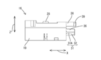
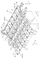
- FIG. 1 is an overall perspective view showing a battery module to which a battery wiring module according to an embodiment of the present invention is attached.
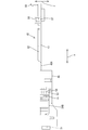
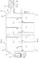
- FIG. 2 is a plan view showing a state in which the cover, the first end cover, and the second end cover of the battery module are opened.
- FIG. 3 is a plan view showing the connecting unit.
- FIG. 4 is a rear view showing the connecting unit.
- FIG. 5 is a front view showing the connecting unit.
- FIG. 6 is a side view showing the connecting unit.
- 7 is a cross-sectional view taken along line VII-VII in FIG.
- FIG. 8 is an enlarged plan view of a main part showing a locking structure between the cover engaging portion and the cover engaging receiving portion.
- FIG. 9 is a plan view showing the first end connecting unit.
- FIG. 10 is a front view showing the first end connecting unit.
- FIG. 11 is a side view showing the first end connecting unit.
- FIG. 12 is a plan view showing the second end connecting unit.
- FIG. 13 is a front view showing the second end connecting unit.
- FIG. 14 is a side view showing the second end connecting unit.
- FIG. 15 is a rear view showing the second end connecting unit.
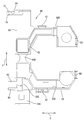
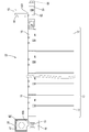
- FIG. 16 is a plan view showing a connecting battery wiring module.
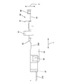
- FIG. 17 is a plan view showing a battery wiring module for external connection.
- FIG. 18 is a perspective view showing a state in which the battery wiring module is assembled to the unit cell group.
- FIG. 19 is a plan view showing a state in which the first end cover and the second end cover are opened by the sub hinge.
- FIG. 20 is a side view showing a state in which the first end cover and the second end cover are opened by the sub hinge.
- FIG. 21 is a plan view showing a state in which the first end cover and the second end cover are closed by the sub hinge.
- FIG. 22 is a side view showing a state in which the first end cover and the second end cover are closed by the sub hinge.
- the battery module 10 to which the battery wiring module 14 according to the present embodiment is attached is mounted on a vehicle (not shown) such as an electric vehicle or a hybrid vehicle, and is used as a power source for driving the vehicle.
- the battery module 10 includes a unit cell group 13 in which a plurality (twelve in the present embodiment) unit cells 12 each having an electrode terminal 11 are arranged side by side.
- the cell groups 13 are electrically connected by a battery wiring module 14.
- the direction indicated by the arrow X in FIG. Specifically, a direction toward the right front side in FIG. 1 is set to the right side, and a direction toward the left back side is set to the left side.
- the direction shown by the arrow line Y in FIG. 1 be the front-back direction.
- the direction toward the left front side in FIG. 1 is defined as the front, and the direction toward the right back side is defined as the rear.
- the direction shown by the arrow line Z in FIG. 1 be an up-down direction.
- the lower side in FIG. 1 is the lower side, and the upper side is the upper side.
- symbol may be attached
- the unit cell 12 has a flat rectangular parallelepiped shape.
- a power generation element (not shown) is accommodated inside the unit cell 12.
- a pair of electrode terminals 11, 11 are formed on the upper surface of the unit cell 12 so as to protrude upward at positions near both ends in the front-rear direction.
- One of the electrode terminals 11 is a positive terminal, and the other is a negative terminal.
- a screw thread is formed on the outer surface of the electrode terminal 11.
- the unit cells 12 are arranged so that the adjacent electrode terminals 11 have different polarities.
- the plurality of unit cells 12 are arranged in the left-right direction to form a unit cell group 13.
- the battery wiring module 14 arranged on the front side in FIG. 1 and connecting the adjacent single cells 12 is a connecting battery wiring module 14A, and the adjacent single cells 12 arranged on the back side in FIG.
- the battery wiring module 14 that connects and connects the cell group 13 to the power conductor 15 disposed in the vehicle is an external connection battery wiring module 14B.
- the connecting battery wiring module 14 ⁇ / b> A includes a plurality (six in this embodiment) of connecting units 16 connected in the left-right direction.
- the alignment direction of the connection units 16 is the same as the alignment direction of the cells 12 in the cell group 13.
- a connecting member 17 that connects the electrode terminals 11 of the adjacent unit cells 12 is attached to the connecting unit 16.
- the connecting member 17 is formed by pressing a metal plate made of copper, copper alloy, SUS, or the like into a predetermined shape.
- the connection member 17 has a rectangular shape extending in the left-right direction when viewed from above.
- the connection member 17 is formed with an electrode terminal through hole 18 ⁇ / b> A through which the electrode terminal 11 penetrates, through the connection member 17.
- the connecting unit 16 is formed with a synthetic resin accommodating portion 19 in which the connecting member 17 is accommodated.
- the accommodating portion 19 has a rectangular shape when viewed from above, and is slightly larger than the connecting member 17.
- An opening 20 ⁇ / b> A that opens upward is formed in the accommodating portion 19, and the connection member 17 is accommodated in the accommodating portion 19 from the opening 20 ⁇ / b> A.
- the electrode terminal 11 is electrically connected to the connection member 17 by screwing the nut 21 in a state of being penetrated into the electrode terminal through hole 18A of the connection member 17.
- the voltage detection terminal 22 is sandwiched between the nut 21 and the connection member 17 on one of the adjacent electrode terminals 11 connected by the connection member 17. Thereby, the voltage detection terminal 22 and the electrode terminal 11 are electrically connected.
- One end of a voltage detection line 23 is connected to the voltage detection terminal 22 by a known method such as crimping.
- the other end of the voltage detection line 23 is connected to an ECU (not shown).
- the connecting unit 16 is formed with a synthetic resin wire routing portion 24 ⁇ / b> A that accommodates the voltage detection wire 23 and is routed in the left-right direction.
- the electric wire routing portion 24A has a substantially groove shape when viewed from the left-right direction, and can accommodate the voltage detection line 23. 24 A of electric wire routing parts and the accommodating part 19 are connected (connected) by the connection part 25A made from a synthetic resin.
- the connecting portion 25A has a groove shape including a plate-like bottom portion 71 and a pair of groove walls 72A and 72B provided on the left and right sides of the bottom portion 71, and voltage detection connected to the voltage detection terminal 22 at the bottom portion 71.
- the terminal part of the line 23 is arranged.
- a pair of claw portions 73 protrudes inward from the upper ends of the pair of groove walls 72A and 72B, and the voltage detection line 23 can be held in the connecting portion 25 by the pair of claw portions 73.
- a cover 27 made of synthetic resin is integrally formed in the accommodating portion 19 through a hinge 26 from the side surface opposite to the connecting portion 25A.
- the cover 27 is rotatable about the hinge 26.
- the cover 27 has a substantially rectangular shape when viewed from above.
- the cover 27 is set to a size that can cover the accommodating portion 19, the connecting portion 25 ⁇ / b> A, and the electric wire routing portion 24 ⁇ / b> A.
- the cover 27 is elastically engaged with a cover lock portion 28 formed on the cover 27 and a cover lock receiving portion 29 formed on the electric wire routing portion 24, so that the accommodating portion 19, the connecting portion 25 ⁇ / b> A, It is held in a state of covering the electric wire routing portion 24A.
- the cover 27 is formed with ribs 30 projecting toward the accommodating portion 19 on the surface located on the accommodating portion 19 side in a state where the cover 27 is closed.
- the rib 30 is formed in a closed loop shape having a substantially rectangular shape.
- the rib 30 is formed so as to enter the housing portion 19 with the cover 27 closed. Specifically, it is formed in a shape slightly smaller than the lip of the opening 20 ⁇ / b> A of the housing portion 19.
- a locking portion 31 protruding outward is formed at the left end portion (corresponding to the locking end portion) of the connecting unit 16 (in the connecting portion 25A).
- the locking portion 31 protrudes downward at the tip of the plate-like bending piece 31 ⁇ / b> A and the bending piece 31 ⁇ / b> A and is locked to the hole edge portion of the first engagement hole 34. It consists of a protrusion 32.
- the above-mentioned downward is a direction orthogonal to the connection direction and means a direction orthogonal to the connection direction of the connection member 17.
- the bending piece 31 ⁇ / b> A is curved upward on the base end portion 31 ⁇ / b> B side, and the base end portion 31 ⁇ / b> B is integrated with the upper end portion of the groove wall 72 ⁇ / b> A of the connecting portion 25.
- the locking protrusion 32 protrudes downward in a step shape, and has a shape in which the protrusion dimension decreases in an inclined manner toward the distal end side.
- a locking receiving portion 33 that is locked to the locking portion 31 is formed at the right end portion (corresponding to the opening end portion) of the connecting unit 16.
- the latch receiving portion 33 is formed in a U shape with an upper surface opened, and the first engagement hole 34 provided in the latch receiving portion 33 penetrates in the left-right direction.
- the locking protrusion 32 penetrates through the inside of the first engagement hole 34 to the hole edge of the first engagement hole 34 (the end in the connecting direction of the locking receiving portion 33).
- the stepped portion of the locking protrusion 32 comes into contact.
- a predetermined clearance 35 ⁇ / b> A is formed between the locking receiving portion 33 (first engagement hole 34) and the locking projection 32.
- the predetermined clearance 35A is a clearance formed between the engagement hole and the locking protrusion when a locking structure in which the locking protrusion is generally locked to the hole edge of the engagement hole is adopted.
- the clearance 35A formed between the hole edge of the first engagement hole 34 and the locking projection 32 is 0.2 mm.
- the dimension range of the clearance 35A can be arbitrarily set as necessary.
- the variation regulating piece 36 has a flat plate shape in the front-rear direction (the direction indicated by the arrow Y in FIG. 3). In other words, the variation regulating piece 36 has a shape with a large thickness (thickness) in the vertical direction. Thereby, the direction (front-rear direction) in which the locking portion 31 is made thick and the direction (up-down direction) in which the variation regulating piece 36 is made thick have a perpendicular relationship.
- the front end of the variation regulating piece 36 is substantially the same position as the front end of the locking portion 31 in the connecting direction.
- the right end portion (corresponding to the opening end portion) of the connecting unit 16 is connected to the accommodating portion 19 and the wire routing portion 24, and the connected portion includes a left-right direction.
- a second engagement hole 37 with which the variation regulating piece 36 inserted in (the connection direction of the connection unit 16) is engaged is provided side by side with the first engagement hole 34.
- the second engagement hole 37 is a through-hole penetrating in the left-right direction through which the variation regulating piece 36 can be inserted.
- the rotation (with a predetermined value or more) about the front end side of the locking portion 31 is restricted between the movement restriction pieces 36 and the fluctuation restriction piece 36 and the second relation within a range in which this rotation (fluctuation) can be restricted.
- a clearance with the joint hole 37 is set.
- a cover engaging portion 38 that protrudes outward is formed at the left end portion of the cover 27 (one of the left and right side edges).
- the cover engaging portion 38 is formed by being divided into two forks, and at each tip portion, a cover engaging claw 39 is formed so as to protrude outward in the front-rear direction (direction indicated by arrow Y in FIG. 3). ing.
- a cover engagement receiving portion 40 that engages with the cover engagement portion 38 is formed on the side edge opposite to the side edge where the cover engagement portion 38 is formed.
- a cover engagement hole 41 through which the cover engagement claw 39 is penetrated is formed in the cover engagement receiving portion 40 so as to penetrate in the left-right direction.
- the cover engagement claw 39 penetrates the inside of the cover engagement hole 41 and penetrates the cover engagement hole 41 at the hole edge of the cover engagement hole 41. It comes in contact with the front side of the direction.
- a predetermined clearance 35 ⁇ / b> B is formed between the cover engagement hole 41 and the cover engagement claw 39.
- the predetermined clearance 35B generally refers to a clearance formed between the engagement hole and the engagement claw when a locking structure in which the engagement claw is locked to the hole edge of the engagement hole is employed. . This is because if the clearance 35B is not formed, there may occur a case where the engaging claw cannot be locked to the hole edge portion of the engaging hole even by a slight dimensional error.
- the clearance 35B formed between the hole edge of the cover engagement hole 41 and the cover 27 locking claw is 0.2 mm. The dimension range of the clearance 35B can be arbitrarily set as necessary.
- the connecting battery wiring module 14 ⁇ / b> A includes a locking portion 31, a first engaging hole 34 (locking receiving portion 33), a variation regulating piece 36, a second engaging hole 37, and a cover engaging portion. 38 and the cover engagement receiving part 40 engage, and the connection unit 16 is connected and formed in the left-right direction.
- the external connection battery wiring module 14 ⁇ / b> B arranged on the rear side includes a plurality of (in this embodiment, five) connection units 16 connected in the left-right direction and the left end portions of the plurality of connection units 16 connected.
- a first end connection unit 42 connected to the right end of the plurality of connection units 16 connected to the second end connection unit 43.
- the arrangement direction of the first end connection unit 42, the connection unit 16, and the second end connection unit 43 is the same as the arrangement direction of the cells 12 in the cell group 13.
- the first end connection unit 42 includes the electrode terminal 11 on the rear side of the unit cell 12 located at the left end of the unit cell group 13 and the power conductor 15 disposed in the vehicle. It has the 1st end part connection member 44 to connect.
- the first end connection member 44 is formed by pressing a metal plate made of copper, copper alloy, SUS, or the like into a predetermined shape.
- the first end connection member 44 has a bent shape elongated in the vertical direction when viewed from above.
- An electrode terminal through hole 18B through which the electrode terminal 11 passes is formed at the rear end portion of the first end connection member 44, and a bolt (not shown) is passed through the front end portion of the first end connection member 44.
- a bolt through hole 45A is formed.
- the first end connecting member 44 and the power conductor 15 are sandwiched between the bolt head and the nut by screwing a bolt inserted into the bolt through hole 45A into a nut (not shown). Fixed in state.
- the first end connecting unit 42 is formed with a first end connecting member accommodating portion 46 made of synthetic resin in which the first end connecting member 44 is accommodated.
- the first end connection member accommodating portion 46 has a shape that follows the first end connection member 44 as viewed from above, and has a slightly larger shape.
- An opening 20B that opens upward is formed in the first end connecting member accommodating portion 46, and the first end connecting member 44 is accommodated in the first end connecting member accommodating portion 46 from the opening 20B. It has come to be.
- the electrode terminal 11 is electrically connected to the first end connection member 44 by screwing the nut 21 in a state of being penetrated into the electrode terminal through hole 18B of the first end connection member 44.
- the voltage detection terminal 22 is sandwiched between the nut 21 and the first end connection member 44. Thereby, the voltage detection terminal 22 and the electrode terminal 11 are electrically connected.
- One end of a voltage detection line 23 is connected to the voltage detection terminal 22 by a known method such as crimping.
- the other end of the voltage detection line 23 is connected to an ECU (not shown).
- the first end connection unit 42 is formed with a synthetic resin wire routing portion 24B that accommodates the voltage detection wire 23 and is wired in the left-right direction.
- the electric wire routing portion 24B has a generally groove shape when viewed from the left-right direction, and can accommodate the voltage detection line 23.
- the electric wire routing portion 24B and the first end connection member accommodation portion 46 are connected by a connecting portion 25B made of synthetic resin.
- the voltage detection terminal 22 is held in the connecting portion 25B.
- a first end cover 47 made of synthetic resin is integrally formed on the first end connection member accommodating portion 46 from the side surface opposite to the connecting portion 25B via a main hinge 48A.
- the first end cover 47 is rotatable about the main hinge 48A.
- the first end cover 47 generally has a shape that follows the first end connection member accommodating portion 46, the connecting portion 25B, and the electric wire routing portion 24B as viewed from above.
- the first end cover 47 is set to a size that can cover the first end connection member accommodating portion 46, the connecting portion 25B, and the wire routing portion 24B.
- the first end cover 47 is further formed with a sub hinge 49A.
- the first end cover 47 is formed to be rotatable around the sub hinge 49A.
- this sub hinge 49A a portion of the first end cover 47 corresponding to a region where the first end connection member 44 and the power conductor 15 are connected can be opened and closed.
- the first end cover 47 includes a first end cover lock portion 50 formed in the first end cover 47 and a first end portion formed in the first end connection member accommodating portion 46.
- the first end connection member accommodating portion 46, the connecting portion 25B, and the electric wire routing portion 24B are held in a covered state. Yes.
- the first end cover 47 is connected to the first end cover 47 on the surface located on the first end connection member accommodating portion 46 side in a state where the first end cover 47 is closed.
- a first end-side rib 52 that protrudes toward the member accommodating portion 46 is formed.
- the first end side rib 52 is formed so as to enter the first end connection member accommodating portion 46 in a state where the first end cover 47 is closed.
- a first end lock receiving portion 53 that engages with a lock 31 formed on the connection unit 16 disposed on the right side of the first end connection unit 42. Is formed.
- the first end locking receiving portion 53 is formed with a first end first engaging hole 54 through which the locking protrusion 32 penetrates in the left-right direction. ing.
- the engaging structure between the engaging portion 31 and the first end portion engaging receiving portion 53 (first end first engaging hole 54) is the same as the engaging portion 31 and the engaging receiving portion 33 (shown in FIG. 7). Since it is substantially the same as the engagement structure with the first engagement hole 34), a duplicate description is omitted.
- the fluctuation regulating piece 36 formed on the connection unit 16 disposed on the right side of the first end connection unit 42 is engaged with the right edge of the first end connection unit 42.
- a first end second engagement hole 55 is formed.
- the first end second engagement hole 55 is a through-hole penetrating in the left-right direction through which the variation regulating piece 36 can penetrate.
- first end cover 47 As shown in FIGS. 9 and 11, on the right edge of the first end cover 47, a cover engaging portion 38 formed on the cover 27 of the connecting unit 16 located on the right side of the first end connecting unit 42, A first end cover engagement receiving portion 56 to be engaged is formed.
- the first end cover engagement receiving portion 56 is formed with a first end cover engagement hole 57 through which the cover engagement claw 39 penetrates in the left-right direction.
- the engagement structure between the cover engaging portion 38 and the first end cover engagement receiving portion 56 is substantially the same as the engagement structure between the cover engaging portion 38 and the cover engagement receiving portion 40 shown in FIG. Since they are the same, redundant description is omitted.
- the first end connecting unit 42 is connected to the left end of the connected multi-unit connecting unit 16. Specifically, the configuration in which the locking portion 31 and the first end portion locking receiving portion 53 are engaged, and the configuration in which the cover engaging portion 38 and the first end cover engaging receiving portion 56 are engaged, The first end connecting unit 42 and the connecting unit 16 are connected.
- the second end connection unit 43 includes a rear electrode terminal 11 of the unit cell 12 located at the right end of the unit cell group 13, a power conductor 15 disposed in the vehicle,
- the second end connection member 58 is connected.
- the second end connection member 58 is formed by pressing a metal plate made of copper, copper alloy, SUS or the like into a predetermined shape.
- the second end connection member 58 has a bent shape elongated in the left-right direction when viewed from above.
- An electrode terminal through-hole 18C through which the electrode terminal 11 passes is formed at the left end of the second end connection member 58, and a bolt (not shown) is passed through at the right end of the second end connection member 58.
- a through hole 45B is formed.
- the second end connecting member 58 and the power conductor 15 are sandwiched between the bolt head and the nut by screwing a bolt inserted into the bolt through hole 45B into a nut (not shown). Fixed in state.
- the second end connecting unit 43 is formed with a second end connecting member housing 59 made of synthetic resin in which the second end connecting member 58 is housed.
- the second end connection member accommodating portion 59 has a shape following the first end connection member 44 as viewed from above, and has a slightly larger shape.
- the second end connecting member accommodating portion 59 is formed with an opening 20C that opens upward, and the second end connecting member 58 is accommodated in the second end connecting member accommodating portion 59 from the opening 20C. It has come to be.
- the electrode terminal 11 is electrically connected to the second end connection member 58 by screwing the nut 21 in a state of being penetrated into the electrode terminal through hole 18C of the second end connection member 58.
- the voltage detection terminal 22 is sandwiched between the nut 21 and the second end connection member 58 in the electrode terminal 11. Thereby, the voltage detection terminal 22 and the electrode terminal 11 are electrically connected.
- One end of a voltage detection line 23 is connected to the voltage detection terminal 22 by a known method such as crimping.
- the other end of the voltage detection line 23 is connected to an ECU (not shown).
- the second end connecting unit 43 is formed with a synthetic resin electric wire routing portion 24 ⁇ / b> C that accommodates the voltage detection wire 23 and is routed in the left-right direction.
- the electric cable routing portion 24 ⁇ / b> C has a generally groove shape when viewed from the left-right direction, and can accommodate the voltage detection wire 23.
- 24 C of electric wire routing parts and the 2nd end part connection member accommodating part 59 are connected by the connection part 25C made from a synthetic resin.
- the voltage detection terminal 22 is held at the connecting portion 25C.
- a second end cover 60 made of synthetic resin is integrally formed on the second end connection member accommodating portion 59 from the side surface opposite to the coupling portion 25C via the main hinge 48B.
- the second end cover 60 is rotatable about the main hinge 48B.
- the second end cover 60 generally has a shape that follows the second end connection member accommodating portion 59, the connecting portion 25C, and the wire routing portion 24C as viewed from above.
- the 2nd end part cover 60 is set to the magnitude
- the second end cover 60 includes a second end cover lock part 61 formed on the second end cover 60 and a second end cover member accommodating part 59.
- the end cover lock receiving portion 62 By being elastically engaged with the end cover lock receiving portion 62, the second end connection member accommodating portion 59, the connecting portion 25C, and the wire routing portion 24C are held in a covered state. It has become.
- the second end cover 60 is further formed with a sub hinge 49B as shown in FIG.
- the second end cover 60 is formed to be rotatable around the sub hinge 49B.
- this sub hinge 49 ⁇ / b> B a portion of the second end cover 60 corresponding to a region where the second end connection member 58 and the power conductor 15 are connected can be opened and closed.
- the second end cover 60 includes a second end cover sub-lock portion 63 formed on the second end cover 60 and a second end cover member receiving portion 59 formed on the second end cover member receiving portion 59.
- the second end cover 60 protrudes toward the second end connection member accommodating portion 59 on the surface located on the second end connection member accommodating portion 59 side with the second end cover 60 closed.
- a second end portion side rib 65 is formed.
- the second end portion side rib 65 is formed so as to enter the accommodating portion 19 in a state in which the second end portion cover 60 is closed.
- the second end connecting unit 43 has a left edge that engages with a latch receiving portion 33 formed on the connecting unit 16 disposed on the left side of the second end connecting unit 43.
- a two-end locking portion 66 is formed.
- the second end locking portion 66 is formed to protrude to the left.
- a second end unit engaging claw 67 protruding downward is formed at the tip of the second end locking portion 66.
- the engagement structure between the second end locking portion 66 and the locking receiving portion 33 (first locking hole 34) is the same as the locking portion 31 and the locking receiving portion 33 (first locking shown in FIG. 7). Since it is substantially the same as the engagement structure with the hole 34), redundant description is omitted.
- a variation regulating piece 68 is formed. As shown in FIGS. 12 and 13, the second end variation regulating piece 68 has a flat plate shape in the front-rear direction (the direction indicated by the arrow Y in FIG. 12).
- the second end variation restricting piece 68 is configured to penetrate through the second engagement hole 37 formed in the connection unit 16 disposed on the left side of the second end connection unit 43.
- a second end cover engaging portion 69 protruding leftward is formed on the left edge of the second end cover 60.
- the second end cover engaging portion 69 is formed to be divided into two forks, and the second end cover engaging claws 70 are arranged in the front-rear direction (the direction indicated by the arrow Y in FIG. 12) at each tip portion. Each of them protrudes outward.
- the second end cover engaging portion 69 is adapted to engage with the cover engagement receiving portion 40 of the cover 27 formed on the connecting unit 16 disposed on the left side of the second end connecting unit 43.
- the engagement structure between the second end cover engagement portion 69 and the cover engagement receiving portion 40 is substantially the same as the engagement structure between the cover engagement portion 38 and the cover engagement receiving portion 40 shown in FIG. Since they are the same, redundant description is omitted.
- the second end connecting unit 43 is connected to the right end of the connected multi-unit connecting unit 16. Specifically, the configuration in which the second end locking portion 66 and the locking receiving portion 33 (first engaging hole 34) are engaged, and the second end cover engaging portion 69 and the cover engaging receiving portion 40 are engaged.
- the second end connecting unit 43 and the connecting unit 16 are connected to each other by the configuration in which they are engaged with each other.
- connection units 16 are prepared, and the engagement portions 31 of one connection unit 16 and the engagement receiving portions 33 of the other connection units 16 are sequentially engaged from the left and right directions.
- the cover engaging portion 38 and the cover engaging receiving portion 40 of the other connecting unit 16 are sequentially engaged from the left and right directions.
- the five connection units 16 are connected in the left-right direction.
- the locking portion 31 is locked to the hole edge portion of the first engagement hole 34, and the variation restricting piece 36 is fitted into the second engagement hole 37, so that the direction other than the connecting direction between the two units 16 is exceeded. Since relative movement is restricted, rotation (fluctuation) about the front end side of the locking portion 31 is released so that locking of the locking portion 31 to the edge of the first engagement hole 34 is released. Therefore, the connection units 16 are relatively firmly connected to each other.
- the voltage detection terminal 22 is crimped to one end of the voltage detection line 23, and the voltage detection line 23 and the voltage detection terminal 22 are connected.
- the voltage detection line 23 is routed to the wire routing portion 24A of the connected connection unit 16, each voltage detection terminal 22 is held in each connection portion 25A, and each voltage detection terminal 22 is disposed in each accommodation portion 19. To do. Thereby, as shown in FIG. 16, the connection battery wiring module 14A is completed.
- one first end connecting unit 42, five connecting units 16, and one second end connecting unit 43 are prepared. While engaging the 1st edge part latching receiving part 53 of the 1st edge part connection unit 42 and the engaging part of the connection unit 16 from the left-right direction, it is 1st edge part cover engagement of the 1st edge part connection unit 42.
- the receiving part 56 and the cover engaging part 38 of the connection unit 16 are engaged from the left-right direction.
- the engaging portion 31 of one connecting unit 16 and the engaging receiving portion 33 (first engaging hole 34) of the other connecting unit 16 are engaged from the left and right directions, and the cover member of the one connecting unit 16 is engaged.
- the joining portion 38 and the cover engagement receiving portion 40 of the other connecting unit 16 are engaged from the left and right directions.
- connection unit 16 and the second end portion engagement portion 66 of the second end connection unit 43 are engaged from the left and right directions, and the cover engagement reception portion 40 of the connection unit 16 is engaged.
- the second cover engaging unit 38 of the second end connecting unit 43 is engaged from the left and right directions.
- first end connection member 44 is accommodated inside the first end connection member accommodation portion 46 of the first end connection unit 42.
- the connecting member 17 is accommodated in the accommodating portion 19 of each coupling unit 16.
- the second end connection member 58 is accommodated inside the second end connection member accommodation portion 59 of the second end connection unit 43.
- the voltage detection terminal 22 is crimped to one end of the voltage detection line 23, and the voltage detection line 23 and the voltage detection terminal 22 are connected.
- the voltage detection line 23 is routed to the wire routing portions 24A, 24B, and 24C of the connected first end connection unit 42, connection unit 16, and second end connection unit 43, and the connection portions 25A and 25B. 25C, the respective voltage detection terminals 22 are held, and the respective voltage detection terminals 22 are arranged inside the first end connection member accommodation portion 46, the accommodation portion 19, and the second end connection member accommodation portion 59, respectively.
- the external connection battery wiring module 14B is completed.
- the connecting battery wiring module 14 ⁇ / b> A is attached to the electrode terminal 11 located on the front side of the cell group 13 from above. At this time, the electrode terminal 11 is made to penetrate through the electrode terminal through holes 18A, 18B, 18C of the connection member 17.
- the external connection battery wiring module 14B is attached to the electrode terminal 11 located on the back side of the cell group 13 from above.
- the electrode terminal 11 passes through the electrode terminal through hole 18B of the first end connection member 44, the electrode terminal through hole 18A of the connection member 17, and the electrode terminal through hole 18C of the second end connection member 58. (See FIG. 18).
- each electrode terminal 11 Thereafter, a nut 21 is screwed into each electrode terminal 11. Thereby, as shown in FIG. 2, twelve unit cells 12 are connected in series.
- the plurality of connected covers 27 are rotated about the hinge 26 and closed so as to cover the accommodating portion 19, the connecting portion 25A, and the electric wire routing portion 24A.
- the cover lock portion 28 and the cover lock receiving portion 29 are elastically engaged, whereby the cover 27 is held in a closed state.
- the connected first end cover 47, the plurality of covers 27, and the second end cover 60 are rotated around the main hinges 48A, 48B and the hinge 26. It closes so that the accommodating part 19, connecting part 25A, 25B, 25C, and electric wire routing part 24A, 24B, 24C may be covered.
- the cover lock portion 28 and the cover lock receiving portion 29 are elastically engaged, and the second end cover lock portion 61 and the second end formed in the second end connection member accommodating portion 59 are also provided.
- the first end cover 47, the plurality of covers 27, and the second end cover 60 that are connected are held in a closed state by elastically engaging with the part cover lock receiving part 62.
- the region corresponding to the portion where the part connecting member 58 and the external conductor are connected can be opened and closed around the sub hinge 49 (see FIGS. 19 and 20).
- the power conductor 15 disposed in the vehicle and the first end connecting member 44 are connected by bolting. Further, the power conductor 15 and the second end connection member 58 are connected by bolting. Thereafter, the first end cover 47 is rotated around the sub hinge 49A, and the first end cover lock portion 50 and the first end cover lock receiving portion 51 are elastically engaged. As a result, the first end cover 47 is held in a state of covering the first end connection member accommodating portion 46. Further, the second end cover 60 is rotated about the sub hinge 49B, and the second end cover sub lock portion 63 and the second end cover sub lock receiving portion 64 are elastically engaged. Thereby, the 2nd end part cover 60 is hold
- a battery wiring module 14 attached to a unit cell group 13 in which a plurality of unit cells 12 having positive and negative electrode terminals 11 are arranged, and a plurality of units electrically connecting the electrode terminals 11 of adjacent unit cells 12.
- a plurality of connecting units 16 that hold the connecting member 17, an opening end portion that is located on one side of the connecting unit 16 in the connecting direction and has a first engagement hole 34 that opens in the connecting direction; It is located on the other side of the connecting direction in the connecting unit 16, and is inserted into the first engaging hole 34 of the connecting unit 16 located adjacent to the connecting direction and locked to the hole edge of the first engaging hole 34.
- the variation regulating piece 36 has an opening end portion. And provided at the other end of the locking end in the connecting direction. It is inserted through the second engagement hole 37, the coupling unit 16 adjacent to regulate the varying to the connecting direction (insertion direction) different from directions.
- the locking portion 31 is locked to the hole edge portion of the first engagement hole 34 that opens in the connecting direction of the connecting unit 16, it is possible to reliably connect the connecting units 16. It becomes.
- the locking portion 31 when the locking portion 31 is only locked in the first engagement hole 34, for example, when one unit rotates around the distal end side of the locking portion 31, the locking of the locking portion 31 is released.
- the variation regulating piece 36 in addition to the locking portion 31, the variation regulating piece 36 is inserted into the second engagement hole 37 to regulate variation in a direction different from the coupling direction.
- the locking portion 31 includes a plate-like bending piece 31A, and a locking protrusion that protrudes to the side orthogonal to the connecting direction on the distal end side of the bending piece 31A and is locked to the hole edge portion of the first engagement hole 34. 32. If it does in this way, it will become possible to lock the latching
- the fluctuation regulating piece 36 has a thick shape in the thickness direction of the bending piece 31A. If it does in this way, it will become possible to regulate rotation centering on the tip side of locking part 31 of connecting unit 16 certainly with simple composition.
- the present invention is not limited to the embodiments described with reference to the above description and drawings.
- the following embodiments are also included in the technical scope of the present invention.
- the first engagement hole 34 and the second engagement hole 37 are provided on the right end side (one side in the connection direction, the open end) of the connection unit 16,
- the variation restricting piece 36 is provided on the left end side (the other side in the connecting direction, the engaging end portion) of the connecting unit 16, but is not limited to this, and the engaging portion 31 and the variation restricting piece 36 (the first one)
- the first engagement hole 34 and the second engagement hole 37) may be provided on different sides of the connection unit 16 in the connection direction.
- first engagement hole 34 and the variation regulating piece 36 are provided on one side (opening end side) in the connection direction of the connection unit 16, and the second engagement hole 37 and the locking portion 31 are provided. You may make it provide in the other side (locking edge part side) in the connection direction of the connection unit 16.
- connecting units 16 are connected.
- the present invention is not limited to this, and two to four, or seven or more, any, as required
- the number of connecting units 16 may be connected.
- First end connecting member accommodating portion 47 ... first end cover 48A, 48B ... main hinge 49A, 49B ... sub hinge 52 ... first end side rib 53 ... first 1 end locking receiving portion 54 ... first end first engaging hole 56 ... first end cover engaging receiving portion 57 ... first end cover engaging hole 58 ... first 2 end connection member 59 ... 2nd end connection member accommodating part 60 ... 2nd end cover 65 ... 2nd edge part side rib 66. .. Second end locking portion 67 ... Second end unit engaging claw 69 ... Second end cover engaging portion 70 ... Second end cover engaging claw 71 ... Bottom 72A, 72B ... groove wall
Priority Applications (3)
| Application Number | Priority Date | Filing Date | Title |
|---|---|---|---|
| US14/129,753 US9088040B2 (en) | 2011-07-05 | 2012-06-15 | Cell wiring module |
| CN201280030041.4A CN103620822B (zh) | 2011-07-05 | 2012-06-15 | 电池布线模块 |
| EP12807244.4A EP2713421A4 (de) | 2011-07-05 | 2012-06-15 | Zellenverkabelungsmodul |
Applications Claiming Priority (2)
| Application Number | Priority Date | Filing Date | Title |
|---|---|---|---|
| JP2011149074A JP5733061B2 (ja) | 2011-07-05 | 2011-07-05 | 電池配線モジュール |
| JP2011-149074 | 2011-07-05 |
Publications (1)
| Publication Number | Publication Date |
|---|---|
| WO2013005558A1 true WO2013005558A1 (ja) | 2013-01-10 |
Family
ID=47436915
Family Applications (1)
| Application Number | Title | Priority Date | Filing Date |
|---|---|---|---|
| PCT/JP2012/065339 WO2013005558A1 (ja) | 2011-07-05 | 2012-06-15 | 電池配線モジュール |
Country Status (5)
| Country | Link |
|---|---|
| US (1) | US9088040B2 (de) |
| EP (1) | EP2713421A4 (de) |
| JP (1) | JP5733061B2 (de) |
| CN (1) | CN103620822B (de) |
| WO (1) | WO2013005558A1 (de) |
Cited By (1)
| Publication number | Priority date | Publication date | Assignee | Title |
|---|---|---|---|---|
| WO2014010557A1 (ja) * | 2012-07-09 | 2014-01-16 | 矢崎総業株式会社 | バスバモジュール |
Families Citing this family (15)
| Publication number | Priority date | Publication date | Assignee | Title |
|---|---|---|---|---|
| JP5803630B2 (ja) * | 2011-12-06 | 2015-11-04 | 株式会社オートネットワーク技術研究所 | 電池配線モジュール |
| JP6220547B2 (ja) * | 2013-05-08 | 2017-10-25 | 矢崎総業株式会社 | バスバモジュール |
| JP6130733B2 (ja) * | 2013-05-27 | 2017-05-17 | 矢崎総業株式会社 | バスバーモジュール |
| JP6186922B2 (ja) * | 2013-06-18 | 2017-08-30 | 住友電装株式会社 | 配線モジュール |
| FR3017023B1 (fr) * | 2014-01-29 | 2017-01-06 | Hypertac Sa | Systeme pour connecter electriquement au moins un premier equipement et un deuxieme equipement entre eux |
| JP6536314B2 (ja) * | 2015-09-16 | 2019-07-03 | 株式会社オートネットワーク技術研究所 | 配線モジュール |
| WO2017047372A1 (ja) * | 2015-09-16 | 2017-03-23 | 株式会社オートネットワーク技術研究所 | 端子及び配線モジュール |
| JP6658122B2 (ja) * | 2016-03-10 | 2020-03-04 | 株式会社オートネットワーク技術研究所 | 蓄電モジュールと制御機器との接続構造 |
| EP3465799B1 (de) | 2016-06-01 | 2021-04-21 | Termaco Ltee | Batterieanschluss |
| JP6699464B2 (ja) * | 2016-09-05 | 2020-05-27 | 株式会社オートネットワーク技術研究所 | 接続モジュール |
| JP6772937B2 (ja) * | 2017-04-10 | 2020-10-21 | 株式会社オートネットワーク技術研究所 | 蓄電パックのベースプレート構造、および蓄電パック |
| CN109390536B (zh) * | 2017-08-04 | 2021-04-23 | 莫仕连接器(成都)有限公司 | 电池连接模块 |
| US11862817B2 (en) * | 2018-02-14 | 2024-01-02 | Gs Yuasa International Ltd. | Energy storage apparatus |
| JP7184606B2 (ja) * | 2018-11-20 | 2022-12-06 | 日本メクトロン株式会社 | 支持部材及びバッテリモジュール |
| KR20230102738A (ko) * | 2021-12-30 | 2023-07-07 | 삼성에스디아이 주식회사 | 버스 바 홀더, 버스 바 조립체 및 전지 모듈 |
Citations (5)
| Publication number | Priority date | Publication date | Assignee | Title |
|---|---|---|---|---|
| JP2010225449A (ja) * | 2009-03-24 | 2010-10-07 | Autonetworks Technologies Ltd | 接続ユニット |
| JP2011067012A (ja) * | 2009-09-17 | 2011-03-31 | Yazaki Corp | 電線配索体、バスバモジュール、及び、電源装置 |
| JP2011077031A (ja) * | 2009-09-07 | 2011-04-14 | Yazaki Corp | バスバモジュール、及び、このバスバモジュールを備えた電源装置 |
| JP2011091003A (ja) * | 2009-10-26 | 2011-05-06 | Autonetworks Technologies Ltd | 電池接続アセンブリ |
| JP2011124176A (ja) * | 2009-12-14 | 2011-06-23 | Autonetworks Technologies Ltd | 電池接続アセンブリ |
Family Cites Families (6)
| Publication number | Priority date | Publication date | Assignee | Title |
|---|---|---|---|---|
| JP3523025B2 (ja) | 1997-08-22 | 2004-04-26 | 矢崎総業株式会社 | バッテリ間接続用バスバー |
| CN103943912B (zh) * | 2008-11-12 | 2018-02-27 | 江森自控帅福得先进能源动力系统有限责任公司 | 具有热交换器的电池系统 |
| US7972185B2 (en) * | 2009-03-16 | 2011-07-05 | Sb Limotive Co., Ltd. | Battery module having connector for connecting terminals |
| JP5500336B2 (ja) | 2009-06-23 | 2014-05-21 | 株式会社オートネットワーク技術研究所 | 電池接続アセンブリ |
| DE102009041894A1 (de) * | 2009-09-18 | 2011-03-31 | Bombardier Transportation Gmbh | Elektrisches Kontaktieren eines elektrischen Bauteils |
| KR101137365B1 (ko) * | 2010-05-20 | 2012-04-20 | 에스비리모티브 주식회사 | 배터리 팩 |
-
2011
- 2011-07-05 JP JP2011149074A patent/JP5733061B2/ja not_active Expired - Fee Related
-
2012
- 2012-06-15 EP EP12807244.4A patent/EP2713421A4/de not_active Withdrawn
- 2012-06-15 US US14/129,753 patent/US9088040B2/en not_active Expired - Fee Related
- 2012-06-15 CN CN201280030041.4A patent/CN103620822B/zh not_active Expired - Fee Related
- 2012-06-15 WO PCT/JP2012/065339 patent/WO2013005558A1/ja active Application Filing
Patent Citations (5)
| Publication number | Priority date | Publication date | Assignee | Title |
|---|---|---|---|---|
| JP2010225449A (ja) * | 2009-03-24 | 2010-10-07 | Autonetworks Technologies Ltd | 接続ユニット |
| JP2011077031A (ja) * | 2009-09-07 | 2011-04-14 | Yazaki Corp | バスバモジュール、及び、このバスバモジュールを備えた電源装置 |
| JP2011067012A (ja) * | 2009-09-17 | 2011-03-31 | Yazaki Corp | 電線配索体、バスバモジュール、及び、電源装置 |
| JP2011091003A (ja) * | 2009-10-26 | 2011-05-06 | Autonetworks Technologies Ltd | 電池接続アセンブリ |
| JP2011124176A (ja) * | 2009-12-14 | 2011-06-23 | Autonetworks Technologies Ltd | 電池接続アセンブリ |
Non-Patent Citations (1)
| Title |
|---|
| See also references of EP2713421A4 * |
Cited By (2)
| Publication number | Priority date | Publication date | Assignee | Title |
|---|---|---|---|---|
| WO2014010557A1 (ja) * | 2012-07-09 | 2014-01-16 | 矢崎総業株式会社 | バスバモジュール |
| US9190651B2 (en) | 2012-07-09 | 2015-11-17 | Yazaki Corporation | Bus bar module |
Also Published As
| Publication number | Publication date |
|---|---|
| JP5733061B2 (ja) | 2015-06-10 |
| US20140134894A1 (en) | 2014-05-15 |
| CN103620822A (zh) | 2014-03-05 |
| EP2713421A1 (de) | 2014-04-02 |
| EP2713421A4 (de) | 2015-04-15 |
| JP2013016379A (ja) | 2013-01-24 |
| CN103620822B (zh) | 2016-06-29 |
| US9088040B2 (en) | 2015-07-21 |
Similar Documents
| Publication | Publication Date | Title |
|---|---|---|
| JP5733061B2 (ja) | 電池配線モジュール | |
| JP5880930B2 (ja) | 電池接続アセンブリ | |
| WO2013005557A1 (ja) | 電池配線モジュール | |
| JP5834769B2 (ja) | 電池用配線モジュール | |
| JP5772524B2 (ja) | 電池配線モジュール | |
| JP5772525B2 (ja) | 電池配線モジュール | |
| JP5741948B2 (ja) | 電池配線モジュール | |
| JP5720530B2 (ja) | 電池用配線モジュール | |
| US10249865B2 (en) | Bus bar module | |
| JP2013016381A (ja) | 電池配線モジュール | |
| WO2013011756A1 (ja) | 電池配線モジュール | |
| WO2014203713A1 (ja) | 配線モジュール | |
| JP2013004186A (ja) | 電池配線モジュール | |
| JP5673465B2 (ja) | 電池配線モジュール | |
| JP5673464B2 (ja) | 電池配線モジュール | |
| WO2013183559A1 (ja) | 配線モジュール | |
| US10516149B2 (en) | Conductive module and battery pack | |
| US10490798B2 (en) | Battery pack | |
| US20210210301A1 (en) | Electrical connection box and wire harness | |
| JP2012186063A (ja) | 電池接続アセンブリ | |
| JP2013098030A (ja) | 配線モジュール | |
| WO2022215478A1 (ja) | 電気接続箱 | |
| JP2022108112A (ja) | ヒューズユニット | |
| JP2014132531A (ja) | 端子接続部品 | |
| CN117044055A (zh) | 电连接箱 |
Legal Events
| Date | Code | Title | Description |
|---|---|---|---|
| 121 | Ep: the epo has been informed by wipo that ep was designated in this application |
Ref document number: 12807244 Country of ref document: EP Kind code of ref document: A1 |
|
| WWE | Wipo information: entry into national phase |
Ref document number: 14129753 Country of ref document: US Ref document number: 2012807244 Country of ref document: EP |
|
| NENP | Non-entry into the national phase |
Ref country code: DE |