WO2012176270A1 - Dispositif de commande de moteur à combustion interne - Google Patents
Dispositif de commande de moteur à combustion interne Download PDFInfo
- Publication number
- WO2012176270A1 WO2012176270A1 PCT/JP2011/064072 JP2011064072W WO2012176270A1 WO 2012176270 A1 WO2012176270 A1 WO 2012176270A1 JP 2011064072 W JP2011064072 W JP 2011064072W WO 2012176270 A1 WO2012176270 A1 WO 2012176270A1
- Authority
- WO
- WIPO (PCT)
- Prior art keywords
- correction value
- control
- amount
- target
- learning
- Prior art date
Links
Images


Classifications
-
- F—MECHANICAL ENGINEERING; LIGHTING; HEATING; WEAPONS; BLASTING
- F02—COMBUSTION ENGINES; HOT-GAS OR COMBUSTION-PRODUCT ENGINE PLANTS
- F02D—CONTROLLING COMBUSTION ENGINES
- F02D41/00—Electrical control of supply of combustible mixture or its constituents
- F02D41/0025—Controlling engines characterised by use of non-liquid fuels, pluralities of fuels, or non-fuel substances added to the combustible mixtures
- F02D41/0047—Controlling exhaust gas recirculation [EGR]
- F02D41/0077—Control of the EGR valve or actuator, e.g. duty cycle, closed loop control of position
-
- F—MECHANICAL ENGINEERING; LIGHTING; HEATING; WEAPONS; BLASTING
- F02—COMBUSTION ENGINES; HOT-GAS OR COMBUSTION-PRODUCT ENGINE PLANTS
- F02D—CONTROLLING COMBUSTION ENGINES
- F02D41/00—Electrical control of supply of combustible mixture or its constituents
- F02D41/24—Electrical control of supply of combustible mixture or its constituents characterised by the use of digital means
- F02D41/2406—Electrical control of supply of combustible mixture or its constituents characterised by the use of digital means using essentially read only memories
- F02D41/2425—Particular ways of programming the data
- F02D41/2429—Methods of calibrating or learning
- F02D41/2441—Methods of calibrating or learning characterised by the learning conditions
-
- F—MECHANICAL ENGINEERING; LIGHTING; HEATING; WEAPONS; BLASTING
- F02—COMBUSTION ENGINES; HOT-GAS OR COMBUSTION-PRODUCT ENGINE PLANTS
- F02D—CONTROLLING COMBUSTION ENGINES
- F02D41/00—Electrical control of supply of combustible mixture or its constituents
- F02D41/24—Electrical control of supply of combustible mixture or its constituents characterised by the use of digital means
- F02D41/2406—Electrical control of supply of combustible mixture or its constituents characterised by the use of digital means using essentially read only memories
- F02D41/2425—Particular ways of programming the data
- F02D41/2429—Methods of calibrating or learning
- F02D41/2451—Methods of calibrating or learning characterised by what is learned or calibrated
- F02D41/2464—Characteristics of actuators
-
- F—MECHANICAL ENGINEERING; LIGHTING; HEATING; WEAPONS; BLASTING
- F02—COMBUSTION ENGINES; HOT-GAS OR COMBUSTION-PRODUCT ENGINE PLANTS
- F02D—CONTROLLING COMBUSTION ENGINES
- F02D41/00—Electrical control of supply of combustible mixture or its constituents
- F02D41/24—Electrical control of supply of combustible mixture or its constituents characterised by the use of digital means
- F02D41/2406—Electrical control of supply of combustible mixture or its constituents characterised by the use of digital means using essentially read only memories
- F02D41/2425—Particular ways of programming the data
- F02D41/2429—Methods of calibrating or learning
- F02D41/2477—Methods of calibrating or learning characterised by the method used for learning
- F02D41/2483—Methods of calibrating or learning characterised by the method used for learning restricting learned values
-
- F—MECHANICAL ENGINEERING; LIGHTING; HEATING; WEAPONS; BLASTING
- F02—COMBUSTION ENGINES; HOT-GAS OR COMBUSTION-PRODUCT ENGINE PLANTS
- F02B—INTERNAL-COMBUSTION PISTON ENGINES; COMBUSTION ENGINES IN GENERAL
- F02B29/00—Engines characterised by provision for charging or scavenging not provided for in groups F02B25/00, F02B27/00 or F02B33/00 - F02B39/00; Details thereof
- F02B29/04—Cooling of air intake supply
- F02B29/0406—Layout of the intake air cooling or coolant circuit
-
- F—MECHANICAL ENGINEERING; LIGHTING; HEATING; WEAPONS; BLASTING
- F02—COMBUSTION ENGINES; HOT-GAS OR COMBUSTION-PRODUCT ENGINE PLANTS
- F02B—INTERNAL-COMBUSTION PISTON ENGINES; COMBUSTION ENGINES IN GENERAL
- F02B3/00—Engines characterised by air compression and subsequent fuel addition
- F02B3/06—Engines characterised by air compression and subsequent fuel addition with compression ignition
-
- F—MECHANICAL ENGINEERING; LIGHTING; HEATING; WEAPONS; BLASTING
- F02—COMBUSTION ENGINES; HOT-GAS OR COMBUSTION-PRODUCT ENGINE PLANTS
- F02M—SUPPLYING COMBUSTION ENGINES IN GENERAL WITH COMBUSTIBLE MIXTURES OR CONSTITUENTS THEREOF
- F02M26/00—Engine-pertinent apparatus for adding exhaust gases to combustion-air, main fuel or fuel-air mixture, e.g. by exhaust gas recirculation [EGR] systems
- F02M26/13—Arrangement or layout of EGR passages, e.g. in relation to specific engine parts or for incorporation of accessories
- F02M26/22—Arrangement or layout of EGR passages, e.g. in relation to specific engine parts or for incorporation of accessories with coolers in the recirculation passage
- F02M26/23—Layout, e.g. schematics
-
- Y—GENERAL TAGGING OF NEW TECHNOLOGICAL DEVELOPMENTS; GENERAL TAGGING OF CROSS-SECTIONAL TECHNOLOGIES SPANNING OVER SEVERAL SECTIONS OF THE IPC; TECHNICAL SUBJECTS COVERED BY FORMER USPC CROSS-REFERENCE ART COLLECTIONS [XRACs] AND DIGESTS
- Y02—TECHNOLOGIES OR APPLICATIONS FOR MITIGATION OR ADAPTATION AGAINST CLIMATE CHANGE
- Y02T—CLIMATE CHANGE MITIGATION TECHNOLOGIES RELATED TO TRANSPORTATION
- Y02T10/00—Road transport of goods or passengers
- Y02T10/10—Internal combustion engine [ICE] based vehicles
- Y02T10/40—Engine management systems
Definitions
- the present invention relates to a control device for an internal combustion engine.
- Patent Document 1 describes an internal combustion engine equipped with an exhaust gas recirculation device (hereinafter, this device is referred to as an “EGR device”).
- This EGR device is a device that supplies (that is, recirculates) the exhaust gas to the combustion chamber by introducing the exhaust gas discharged from the combustion chamber of the internal combustion engine into the exhaust passage into the intake passage.
- EGR gas the exhaust gas supplied to the combustion chamber by the EGR device
- EGR gas amount the amount of EGR gas supplied to the combustion chamber.
- the EGR device described in Patent Document 1 has an EGR control valve.
- the opening degree of the EGR control valve can be changed.
- the amount of EGR gas can be changed by changing the opening degree of the EGR control valve. That is, the EGR gas amount can be controlled by controlling the opening degree of the EGR control valve.
- EGR gas reduces the quantity of the substance (especially nitrogen oxide) produced
- the amount of EGR gas that can optimally reduce the exhaust emission varies depending on the engine operating state (that is, the operating state of the internal combustion engine).
- an EGR gas amount that can optimally reduce the exhaust emission according to the engine operating state is obtained in advance by experiments or the like, and the obtained EGR gas amount is used as a target EGR gas amount for the internal combustion engine.
- the target EGR gas amount is set in accordance with the engine operating state during engine operation (that is, during operation of the internal combustion engine) and stored in the electronic control unit of the engine, and the actual EGR amount is set to the set target EGR gas amount.
- the opening degree of the EGR control valve is controlled so that the gas amounts match.
- a correction value for correcting a parameter value (hereinafter referred to as “control parameter value”) that affects the calculation of the operation amount given to the EGR control valve. )
- the control parameter value is corrected by the instantaneous correction value, and the operation amount given to the EGR control valve is calculated using the corrected control parameter value.
- learning addition value a value calculated by multiplying the instantaneous correction value by a coefficient smaller than “1”
- learning correction value a value calculated by multiplying the instantaneous correction value by a coefficient smaller than “1”
- learning correction value a learning value calculated by multiplying the instantaneous correction value by a coefficient smaller than “1”
- control parameter value is calculated based on the deviation and the already calculated learning correction. It is possible to employ a control (hereinafter referred to as “learning control”) in which an operation amount given to the EGR control valve is calculated using the corrected control parameter value.
- an excessively large instantaneous correction value that is, When an instantaneous correction value that is far from an appropriate instantaneous correction value that can converge the EGR gas amount to the target EGR gas amount with a stable behavior is calculated, an excessively large learning addition value (that is, an EGR gas amount) May be calculated as a learning addition value that causes a learning correction value that is significantly different from an appropriate learning correction value that can be converged to the target EGR gas amount with a stable behavior.
- an excessively large learning correction value That is, a learning correction value that is far from an appropriate learning correction value that can converge the EGR gas amount to the target EGR gas amount with a stable behavior is calculated.
- the control parameter value is corrected by the excessively large learning correction value and the instantaneous correction value calculated next, and when the corrected control parameter value is used for calculation of the operation amount given to the EGR control valve, The amount of EGR gas changes while exhibiting unstable behavior. That is, the control of the EGR gas amount becomes unstable.
- the learning correction value includes a deviation of the EGR gas amount from the target EGR gas amount (hereinafter referred to as target EGR) caused by a steady error related to the operation of the EGR control valve (hereinafter referred to as “EGR control valve steady error”).
- the deviation of the EGR gas amount relative to the amount is called “EGR gas amount deviation”). That is, in order to calculate the operation amount to be given to the EGR control valve, the relationship between the EGR gas amount and the operation amount when the operation amount is given to the control target is obtained in advance. Then, an operation amount to be applied to the EGR control valve is calculated from the obtained relationship and the target EGR gas amount, and the calculated operation amount is applied to the EGR control valve.
- the operation characteristic of the EGR control valve with respect to a given operation amount is the same as the operation characteristic of the EGR control valve used to obtain the above relationship (hereinafter, this operation characteristic is referred to as “the desired operation characteristic”). If the environment surrounding the EGR control valve is the same as the environment assumed when the above relationship is obtained (hereinafter, this environment is referred to as “the desired ambient environment”), the operation amount calculated using the above relationship is By giving the EGR control valve, the amount of EGR gas should match the target amount of EGR gas. However, in practice, since the operation characteristics of the EGR control valve differ depending on the individual EGR control valves, the operation characteristics of the EGR control valve may differ from the intended operation characteristics.
- the EGR gas amount does not match the target EGR gas amount.
- the environment surrounding the EGR control valve may be different from the intended surrounding environment.
- the EGR gas amount does not match the target EGR gas amount even if the operation amount calculated using the above relationship is given to the EGR control valve. In such a case, it can be said that an EGR control valve steady-state error has occurred in the EGR control valve.
- the learning correction value has a function of eliminating such an EGR control valve steady-state error.
- the learning correction value increases as the learning correction value is calculated, that is, the learning correction value progresses.
- Approaches a value that can completely eliminate the EGR control valve steady-state error hereinafter, this value is referred to as a “learning value”. Therefore, in order to increase the followability of the EGR gas amount with respect to the target EGR gas amount, it is preferable that the learning correction value reaches the learning value as soon as possible.
- the instantaneous correction value is not an excessively large value, but a relatively large learning addition value is calculated from the instantaneous correction value, and the learning correction value is updated by this learning addition value, and is calculated next to the learning correction value.
- the control parameter value is corrected by the instantaneous correction value, and the operation amount given to the EGR control valve is calculated based on the corrected control parameter value. Even if this operation amount is given to the EGR control valve, the EGR gas amount If the learning coefficient is fixed at a relatively small constant value, the learning addition value calculated from the instantaneous correction value is excessively small (that is, the behavior of the EGR gas amount is It is an excessively small value compared to the largest learning addition value in a range where it does not become unstable.
- the learning correction value cannot reach the learning value quickly.
- the learning coefficient is fixed to a relatively large constant value, when the instantaneous correction value is excessively large, the learning addition value calculated from the instantaneous correction value becomes excessively large. In this case, since an excessively large learning correction value is calculated, after all, the learning correction value cannot reach the learning value quickly.
- control amount EGR gas amount in the above example
- target EGR gas amount in the above example target EGR gas amount in the above example
- control target in the above example, the EGR control valve
- An object of the present invention is to simultaneously achieve the stability of control of the control amount and the improvement of the learning speed of the learning correction value.
- One aspect of the present invention is an operation state of a control target that should be a target in order to calculate a target control amount that is a target value of the control amount of the control target and to match the control amount with the calculated target control amount.
- a control parameter correction value for correcting a control parameter value that is a parameter value used for setting a target operation state is calculated, and set using the control parameter value corrected by the calculated control parameter correction value.
- the present invention relates to a control device for an internal combustion engine that controls an operation state of a control target according to a target operation state.
- the control device provides an instantaneous correction value for correcting the control parameter value currently used for setting the target operation state of the control target so that the control amount matches the target control amount.
- the learning correction value is obtained by integrating the control calculated based on the deviation of the control amount and the learning addition value that is obtained by correcting the instantaneous correction value by the learning coefficient that is a coefficient for correcting the instantaneous correction value.
- the control parameter correction value is calculated based on the newly calculated instantaneous correction value and the already calculated learning correction value.
- the follow-up form allowed as the follow-up form of the control amount with respect to the target control amount is predetermined as the allowable follow-up form, and the follow-up form of the control amount with respect to the target control amount is
- the range of the control parameter correction value in the allowable follow-up form is determined in advance as the allowable control parameter correction value range.
- control device of the present invention sets the learning coefficient so that the control parameter correction value falls within the allowable control parameter correction value range.
- the following means are generally employed as means for controlling the control amount to the target control amount depending on the controlled object. That is, in order to calculate the operation amount to be given to the control object to control the control amount to the target control amount based on the target control amount, a relationship between the target control amount and the operation amount is obtained in advance, During operation of the engine, an operation amount is calculated based on the target control amount using this relationship, and this operation amount is given to the control target.
- the operation characteristic of the controlled object used when the above relationship is obtained is referred to as “initial operation characteristic”, and the environment surrounding the control object when the above relationship is obtained is referred to as “the desired ambient environment”.
- the above relationship is used to determine the The control amount should match the target control amount by giving the calculated operation amount to the control target.
- the operation characteristics of the controlled object may deviate from the intended operation characteristics. In this case, even if the operation amount calculated using the above relationship is given to the control target, the control amount does not match the target control amount.
- the controlled object when used for a long period of time, the controlled object may be deteriorated, and its operating characteristics may deviate from the intended operating characteristics. Also in this case, even if the operation amount calculated using the above relationship is given to the control object, the control amount does not match the target control amount. Of course, the environment surrounding the controlled object may be different from the intended surrounding environment. Also in this case, even if the operation amount calculated using the above relationship is given to the control object, the control amount does not match the target control amount. Under such circumstances, it can be said that a steady error (hereinafter referred to as “steady operation characteristic error”) of the operation characteristic of the controlled object occurs with respect to the intended operation characteristic.
- steady operation characteristic error hereinafter referred to as “steady operation characteristic error”
- control amount error An error in the control amount with respect to the target control amount (hereinafter, this error is referred to as “control amount error”) is a control amount error resulting from the steady operation characteristic error (hereinafter, this control amount error is referred to as “steady control amount error”).
- steady control amount error When the operating state of the internal combustion engine is in a steady state, it can be said that most of the control amount error is a steady control amount error.
- the instantaneous correction value is calculated based on the control amount error
- the learning addition value is calculated based on the instantaneous correction value
- the learning correction value is calculated based on the learning addition value (that is, the learning correction value is It is updated based on this learning addition value). Therefore, the learning correction value has a function of eliminating the steady control amount error. If the learning correction value is calculated more frequently, that is, if learning of the learning correction value is advanced, the learning correction value is a value that can completely eliminate the steady-state control amount error (hereinafter, this value is referred to as “learning value”). Gradually). Therefore, from the viewpoint of quickly converging the control amount to the target control amount, it is preferable that the learning correction value reaches the learning value early. That is, it is preferable to improve the learning speed of the learning correction value.
- a means for setting the learning coefficient to a relatively large value can be considered.
- this has the following disadvantages. That is, when the learning coefficient is fixed to a relatively large constant value, an excessively large instantaneous correction value (that is, a large value from an appropriate instantaneous correction value that can converge the control amount to the target control amount with a stable behavior).
- an excessively large learning addition value that is, a learning correction value far from an appropriate learning correction value that can converge the control amount to the target control amount with a stable behavior
- a learning addition value that is calculated is calculated.
- an excessively large learning addition value is calculated, and a new learning correction value is calculated using the learning addition value (that is, the learning correction value is updated), an excessively large learning correction value (that is, the learning correction value is updated). Therefore, a learning correction value that is far from an appropriate learning correction value that can converge the control amount to the target control amount with a stable behavior is calculated.
- the excessively large learning correction value is used for calculating the control parameter correction value, the control parameter value is corrected by the control parameter correction value, and the corrected control parameter value is used for controlling the operation state of the control target. If this is done, the controlled variable will change while exhibiting unstable behavior. That is, control of the control amount becomes unstable. However, it is not preferable that the control amount is unstable.
- the learning coefficient is fixed to a constant value. As long as the means is adopted, these cannot be achieved simultaneously. Under such circumstances, the inventor of the present application has come to the idea of variably setting the learning coefficient, and if the learning coefficient is set to any value depending on the situation, ensuring the stability of control of the control amount and learning correction value As a result of repeated studies on whether the improvement of the learning speed can be achieved at the same time, the present invention has been invented.
- the control parameter correction value is within the allowable control parameter correction value range (that is, when the control parameter value corrected by the control parameter correction value is used in the operation state of the control target, the control amount is set to the target control amount.
- the learning coefficient is set to a value within the range of the control parameter correction value that can be converged with a stable behavior. For this reason, even if an excessively large instantaneous correction value is calculated, an excessively large learning addition value is not calculated, and as a result, an excessively large learning correction value is not calculated.
- an excessively large instantaneous correction value is calculated, a learning addition value is calculated based on the instantaneous correction value, a learning correction value is calculated based on the learning addition value, and the learning correction value Even if the control parameter correction value is calculated using the control parameter value and the control parameter value corrected by the control parameter correction value is used for controlling the operation state of the control target, the control amount control is stable. Since learning of the learning correction value proceeds in a stable state, the learning correction value can reach the learning value quickly (that is, the learning speed of the learning correction value is improved). .
- the learning coefficient is set to a large value, a learning addition value is calculated based on the instantaneous correction value using the learning coefficient, and learning is performed based on the learning addition value.
- the control parameter correction value is a value within the allowable control parameter correction value range. That is, in the present invention, when the instantaneous correction value is not an excessively large value, the learning coefficient is set to a large value. Therefore, according to the present invention, the learning correction value can be quickly reached the learning value in a state where the control of the control amount is stabilized (that is, the learning speed of the learning correction value is improved).
- Another invention of the present application calculates a target control amount that is a target value of a control amount of a control target, and an operation state of the control target that should be a target in order to make the control amount coincide with the calculated target control amount
- a control parameter correction value for correcting a control parameter value that is a parameter value used to set a target operation state is calculated, and the control parameter value corrected by the calculated control parameter correction value is used.
- the present invention relates to a control device for an internal combustion engine that controls an operation state of a control target in accordance with a target operation state that is set.
- the control device provides an instantaneous correction value for correcting the control parameter value currently used for setting the target operation state of the control target so that the control amount matches the target control amount.
- the learning correction value is obtained by integrating the control calculated based on the deviation of the control amount and the learning addition value that is obtained by correcting the instantaneous correction value by the learning coefficient that is a coefficient for correcting the instantaneous correction value.
- the control parameter correction value is calculated based on the newly calculated instantaneous correction value and the already calculated learning correction value.
- control device of the present invention sets a larger learning coefficient as the learning correction value already calculated is larger.
- steady operation characteristic error a steady error of the operation characteristic of the control target with respect to the intended operation characteristic.
- the controlled variable error (that is, the controlled variable error with respect to the target controlled variable) includes the steady controlled variable error (that is, the controlled variable error caused by the steady operation characteristic error), and the operating state of the internal combustion engine is When in a steady state, it can be said that most of the controlled variable error is a steady controlled variable error.
- the learning correction value has a function of eliminating the steady control amount error. From the viewpoint of quickly converging the control amount to the target control amount, it is preferable to make the learning correction value reach the learning value early. That is, it is preferable to improve the learning speed of the learning correction value.
- control of the control amount becomes unstable.
- the learning correction value proceeds while the control amount control is unstable, the learning correction value cannot reach the learning value quickly (that is, the learning speed of the learning correction value is improved).
- the learning coefficient is fixed to a relatively small constant value, control of the control amount becomes stable, but the learning correction value cannot reach the learning value quickly.
- the learning coefficient is fixed to a constant value. As long as the means is adopted, these cannot be achieved simultaneously. Under such circumstances, the inventor of the present application has come to the idea of variably setting the learning coefficient, and if the learning coefficient is set to any value depending on the situation, ensuring the stability of control of the control amount and learning correction value As a result of repeated studies on whether the improvement of the learning speed can be achieved at the same time, the present invention has been invented.
- the learning coefficient is set to a larger value as the learning correction value is larger.
- a large learning correction value means that the learning correction value is close to the learning value, and if the learning correction value is close to the learning value, the possibility that an excessive instantaneous correction value is calculated is low. Therefore, even if the learning coefficient is set to a large value when the learning correction value is large, the possibility that an excessive learning addition value is calculated is low. Therefore, the learning correction value updated by the learning addition value calculated at this time is used for calculation of the control parameter correction value, and the control parameter value corrected by this control parameter correction value is used for control of the operation state of the control target. Even if it is performed, the control of the control amount is sufficiently suppressed from becoming unstable. On the other hand, the learning coefficient is large, so that the learning speed of the learning correction value is sufficiently improved.
- the smaller the learning correction value the smaller the learning coefficient is set.
- a small learning correction value means that the learning correction value is far from the learning value, and if the learning correction value is far from the learning value, there is a high possibility that an excessive instantaneous correction value is calculated. Therefore, if the learning coefficient is large, there is a high possibility that an excessive learning addition value is calculated.
- the learning correction value updated by the excessive learning addition value is used for calculation of the control parameter correction value, and the control parameter value corrected by the control parameter correction value is used for controlling the operation state of the control target. If controlled, control of the controlled variable becomes unstable.
- the learning coefficient is set to a smaller value as the learning correction value is smaller.
- the control of the control amount is sufficiently suppressed from being unstable, while the learning coefficient is set to a value corresponding to the learning correction value.
- the learning correction value learning speed is improved in an appropriate manner.
- the control device of the present invention comprises air-fuel ratio control means for controlling the air-fuel ratio of the air-fuel mixture formed in the combustion chamber, the controlled object is the air-fuel ratio control means, and the control amount is in the combustion chamber.
- the air-fuel ratio of the air-fuel mixture formed, the estimated air-fuel ratio that is the estimated value of the air-fuel ratio is the target control amount
- the control parameter value is a parameter used for setting the target operating state of the air-fuel ratio control means
- the control parameter correction value is a correction value for correcting the control parameter value so that the air-fuel ratio of the air-fuel mixture matches the estimated air-fuel ratio, and the instantaneous correction value is the estimated air-fuel ratio of the air-fuel mixture.
- the estimated air-fuel ratio is calculated, Air-fuel mixture
- a control parameter correction value for correcting the control parameter value is calculated so as to match the estimated air-fuel ratio
- the target of the air-fuel ratio control means is calculated using the control parameter value corrected by the calculated control parameter correction value.
- the operating state is set.
- control device of the present invention includes an exhaust gas recirculation device that introduces exhaust gas discharged from the combustion chamber into the exhaust passage into the intake passage, and the exhaust gas recirculation device introduces the amount of exhaust gas introduced into the intake passage.
- Exhaust gas recirculation amount control means for controlling the exhaust gas recirculation amount control means the control parameter value is a parameter value used for setting the target operating state of the exhaust gas recirculation amount control means, and the instantaneous correction value is When the correction value is used to correct the control parameter value currently used for setting the target operating state of the exhaust gas recirculation amount control means so that the air-fuel ratio matches the estimated air-fuel ratio, Then, an estimated air-fuel ratio is calculated, a control parameter correction value for correcting the control parameter value so that the air-fuel ratio of the air-fuel mixture matches the estimated air-fuel ratio is calculated, and based on the calculated control parameter correction value, Target operating state of the exhaust gas recirculation amount control means is set by using the corrected control parameter value each.
- the control device of the present invention sets a target exhaust gas recirculation amount that is a target value of the exhaust gas recirculation amount that is the amount of exhaust gas introduced into the intake passage by the exhaust gas recirculation device, and
- the engine having a value of a predetermined parameter relating to the operation of the internal combustion engine The exhaust gas recirculation amount to be targeted in accordance with the operation parameter value is obtained in advance as a reference exhaust gas recirculation amount
- the control parameter value is the engine operation parameter value
- the engine operation parameter value is the control parameter correction.
- the reference exhaust gas recirculation amount is calculated based on the corrected engine operating parameter value, and the calculated reference exhaust gas recirculation amount is calculated as the target exhaust gas. It is set to be re-circulation amount.
- the control device of the present invention further includes a fuel supply means for supplying fuel to the combustion chamber, and a target that is a target value of the fuel supply amount that is the amount of fuel supplied to the combustion chamber by the fuel supply means.
- a fuel supply amount for supplying fuel to the combustion chamber
- a target that is a target value of the fuel supply amount that is the amount of fuel supplied to the combustion chamber by the fuel supply means.
- the engine operating parameter value is set to the target fuel supply.
- a target fuel supply amount equivalent amount which is a fuel supply amount corresponding to the amount, and the target fuel supply amount equivalent amount is corrected by the control parameter correction value and based on the corrected target fuel supply amount equivalent amount.
- a gas recirculation amount is calculated, and the calculated reference exhaust gas recirculation amount is set as a target exhaust gas recirculation amount.
- the control device of the present invention sets a target exhaust gas recirculation amount that is a target value of the exhaust gas recirculation amount that is the amount of exhaust gas introduced into the intake passage by the exhaust gas recirculation device, and
- the engine operation which is a value of a predetermined parameter relating to the operation of the internal combustion engine
- the target exhaust gas recirculation amount is determined in advance as the reference exhaust gas recirculation amount in accordance with the parameter value
- the control parameter value is the reference exhaust gas recirculation amount, which is based on the engine operating parameter value.
- An exhaust gas recirculation amount is calculated, the calculated reference exhaust gas recirculation amount is corrected by the control parameter correction value, and the corrected reference exhaust gas recirculation amount is the target exhaust gas. It is set in the circulation amount.
- the control device of the present invention further includes a fuel supply means for supplying fuel to the combustion chamber, and a target that is a target value of the fuel supply amount that is the amount of fuel supplied to the combustion chamber by the fuel supply means.
- a fuel supply means for supplying fuel to the combustion chamber
- a target that is a target value of the fuel supply amount that is the amount of fuel supplied to the combustion chamber by the fuel supply means.
- the engine operating parameter value is set to the target fuel supply.
- a target fuel supply amount equivalent amount corresponding to the amount, a reference exhaust gas recirculation amount is calculated based on the target fuel supply amount equivalent amount, and the calculated reference exhaust gas recirculation amount is It is corrected by the control parameter correction value, and the corrected reference exhaust gas recirculation amount is set as the target exhaust gas recirculation amount.
- control device of the present invention further includes supply air amount detection means for detecting the supply air amount that is the amount of air supplied to the combustion chamber, according to the above invention, this corresponds to the target fuel supply amount.
- a target fuel supply amount equivalent amount that is a fuel supply amount is corrected by the control parameter correction value, and is estimated based on the corrected target fuel supply amount equivalent amount and the supply air amount detected by the supply air amount detecting means.
- An air-fuel ratio is calculated.
- (A) is the figure which showed the map utilized in order to acquire the reference
- (B) is used in order to acquire the reference
- (C) is a diagram showing a map used for acquiring a reference EGR rate in the first embodiment. It is the figure which showed the map utilized in order to acquire a correction
- (A) is the figure which showed the map utilized in order to acquire a reference fuel injection valve in 5th Embodiment
- (B) is used in order to acquire the reference
- FIG. It is the figure which showed the map utilized in order to acquire a learning correction value in 5th Embodiment.
- first embodiment One embodiment of the control device for an internal combustion engine of the present invention (hereinafter referred to as “first embodiment”) will be described.
- engine operation means “operation of the internal combustion engine”
- engine speed means “speed of the internal combustion engine”.
- FIG. 1 shows an internal combustion engine to which the control device of the first embodiment is applied.
- the internal combustion engine shown in FIG. 1 is a compression ignition type internal combustion engine (so-called diesel engine).
- 10 is an internal combustion engine
- 20 is a main body of the internal combustion engine
- 21 is a fuel injection valve
- 22 is a fuel pump
- 23 is a fuel supply passage
- 30 is an intake passage
- 31 is an intake manifold
- 32 is an intake pipe
- 33 Throttle valve, 34 intercooler, 35 air flow meter, 36 air cleaner, 37 intake pressure sensor
- 70 is an accelerator pedal
- 71 is an accelerator pedal depression amount sensor
- 72 is a crank position sensor
- 80 is an electronic control device.
- the intake passage 30 includes an intake manifold 31 and an intake pipe 32.
- the exhaust passage 40 includes an exhaust manif
- the electronic control unit 80 is composed of a microcomputer.
- the electronic control unit 80 includes a CPU (microprocessor) 81, a ROM (read only memory) 82, a RAM (random access memory) 83, a backup RAM 84, and an interface 85.
- the CPU 81, ROM 82, RAM 83, backup RAM 84, and interface 85 are connected to each other by a bidirectional bus.
- the fuel injection valve 21 is attached to the main body 20 of the internal combustion engine.
- a fuel pump 22 is connected to the fuel injection valve 21 via a fuel supply passage 23.
- the fuel pump 22 supplies high-pressure fuel to the fuel injection valve 21 via the fuel supply passage 23.
- the fuel injection valve 21 is electrically connected to the interface 85 of the electronic control unit 80.
- the electronic control unit 80 supplies a command signal for causing the fuel injection valve 21 to inject fuel to the fuel injection valve 21.
- the fuel pump 22 is also electrically connected to the interface 85 of the electronic control unit 80.
- the electronic control unit 80 supplies the fuel pump 22 with a control signal for controlling the operation of the fuel pump 22 so that the pressure of the fuel supplied from the fuel pump 22 to the fuel injection valve 21 is maintained at a predetermined pressure.
- the fuel injection valve 21 is attached to the main body 20 of the internal combustion engine so that its fuel injection hole is exposed in the combustion chamber. Therefore, when a command signal is supplied from the electronic control unit 80 to the fuel injection valve 21, the fuel injection valve 21 directly injects fuel into the combustion chamber.
- the intake manifold 31 is branched into a plurality of pipes at one end thereof, and these branched pipes are connected to intake ports (not shown) respectively formed corresponding to the combustion chambers of the main body 20 of the internal combustion engine. Yes.
- the intake manifold 31 is connected to one end of the intake pipe 32 at the other end.
- the exhaust manifold 41 branches into a plurality of pipes at one end thereof, and these branched pipes are connected to exhaust ports (not shown) formed respectively corresponding to the combustion chambers of the main body 20 of the internal combustion engine. Yes.
- the exhaust manifold 41 is connected to one end of the exhaust pipe 42 at the other end.
- the throttle valve 33 is disposed in the intake pipe 32.
- this opening is referred to as “throttle valve opening”
- the flow path area in the intake pipe 32 in the region where the throttle valve 33 is disposed changes.
- the throttle valve 33 is connected to an actuator (hereinafter, this actuator is referred to as “throttle valve actuator”) for changing its operating state (that is, the throttle valve opening).
- the throttle valve actuator is electrically connected to the interface 85 of the electronic control unit 80.
- the electronic control unit 80 supplies a control signal for driving the throttle valve actuator to the throttle valve actuator so as to control the throttle valve opening to the target throttle valve opening.
- the intercooler 34 is disposed in the intake pipe 32 upstream of the throttle valve 33.
- the intercooler 34 cools the air flowing into it.
- the air flow meter 35 is disposed in the intake pipe 32 upstream of the intercooler 34.
- the air flow meter 35 is electrically connected to the interface 85 of the electronic control unit 80.
- the air flow meter 35 outputs an output value corresponding to the amount of air passing therethrough. This output value is input to the electronic control unit 80.
- the electronic control unit 80 calculates the amount of air passing through the air flow meter 35 based on this output value, and hence the amount of air taken into the combustion chamber.
- the intake pressure sensor 37 is disposed in the intake passage 30 (more specifically, the intake manifold 31) downstream of the throttle valve 33.
- the intake pressure sensor 37 is electrically connected to the interface 85 of the electronic control unit 80.
- the intake pressure sensor 37 outputs an output value corresponding to the pressure of the surrounding gas (that is, the pressure of the gas in the intake manifold 31 and the pressure of the gas sucked into the combustion chamber). Based on this output value, the electronic control unit 80 calculates the pressure of the gas around the intake pressure sensor 37, that is, the pressure of the gas sucked into the combustion chamber (hereinafter referred to as “intake pressure”).
- the air-fuel ratio sensor 43 is disposed in the exhaust passage 40 (more specifically, the intake pipe 42).
- the air-fuel ratio sensor 43 is electrically connected to the interface 85 of the electronic control unit 80.
- the air-fuel ratio sensor 43 outputs an output value corresponding to the oxygen concentration in the exhaust gas coming there.
- the electronic control unit 80 calculates the air-fuel ratio of the air-fuel mixture formed in the combustion chamber based on this output value.
- the accelerator pedal depression amount sensor 71 is electrically connected to the interface 85 of the electronic control unit 80.
- the accelerator pedal depression amount sensor 71 outputs an output value corresponding to the depression amount of the accelerator pedal 70. This output value is input to the electronic control unit 80. Based on this output value, the electronic control unit 80 calculates the depression amount of the accelerator pedal 70 and thus the torque required for the internal combustion engine.
- the crank position sensor 72 is disposed in the vicinity of the crankshaft (not shown) of the internal combustion engine.
- the crank position sensor 72 is electrically connected to the interface 85 of the electronic control unit 80.
- the crank position sensor 72 outputs an output value corresponding to the rotational phase of the crankshaft. This output value is input to the electronic control unit 80.
- the electronic control unit 80 calculates the engine speed based on this output value.
- the EGR device 50 includes an exhaust gas recirculation passage (hereinafter referred to as “EGR passage”) 51, an exhaust gas recirculation control valve (hereinafter referred to as “EGR control valve”) 52, and an exhaust gas recirculation cooler (hereinafter referred to as “EGR passage valve”).
- the cooler is referred to as “EGR cooler” 53.
- the EGR device 50 is a device that introduces exhaust gas discharged from the combustion chamber into the exhaust passage 40 into the intake passage 30 via the EGR passage 51.
- One end of the EGR passage 51 is connected to the exhaust passage 40 (more specifically, the exhaust manifold 41) and the other end is connected to the intake passage 30 (more specifically, the intake manifold 31).
- the EGR passage 51 connects the exhaust passage 40 to the intake passage 30.
- the EGR control valve 52 is disposed in the EGR passage 51.
- the EGR control valve 52 has a built-in actuator (hereinafter, this actuator is referred to as an “EGR control valve actuator”) for changing its operating state (that is, the EGR control valve opening).
- the EGR control valve actuator is electrically connected to the electronic control unit 80.
- the electronic control unit 80 supplies a control signal for driving the EGR control valve actuator to the EGR control valve actuator so as to control the EGR control valve opening to the target EGR control valve opening.
- fuel injection amount means “amount of fuel injected from the fuel injection valve”.
- the optimum fuel injection amount is obtained in advance by experiments or the like according to the amount of depression of the accelerator pedal.
- the obtained fuel injection amount is stored in the electronic control unit as a reference fuel injection amount Qb in the form of a map of a function of the accelerator pedal depression amount Dac as shown in FIG.
- the reference fuel injection amount Qb corresponding to the accelerator pedal depression amount Dac at that time is acquired from the map of FIG. 2A, and the acquired reference fuel injection amount Qb becomes the target fuel injection amount. Is set.
- a command signal is supplied from the electronic control unit to the fuel injection valve so that the fuel of the target fuel injection amount thus set is injected from the fuel injection valve.
- the reference fuel injection amount Qb increases as the accelerator pedal depression amount Dac increases.
- the operation state of the internal combustion engine shown in FIG. 1 is maintained in a steady operation state (that is, a state in which the fuel injection amount and the engine speed are kept constant) and the environment surrounding the internal combustion engine.
- a steady operation state that is, a state in which the fuel injection amount and the engine speed are kept constant
- Parameters that affect the engine operating state for example, atmospheric pressure, atmospheric temperature, internal combustion engine temperature, etc., hereinafter referred to as “environmental parameters” have a specific value.
- an appropriate throttle valve opening corresponding to the fuel injection amount and the engine speed is obtained in advance by experiments or the like. Then, as shown in FIG.
- the obtained throttle valve opening is set as a reference throttle valve opening Dthb in the form of a map of a function of the fuel injection amount Q and the engine speed N. Is remembered.
- the reference throttle valve opening Dthb increases as the fuel injection amount Q increases, and the reference throttle valve opening Dthb increases as the engine speed N increases.
- the reference throttle valve opening degree Dthb corresponding to the fuel injection amount Q and the engine speed N at that time is acquired from the map of FIG. 2B, and the acquired reference throttle valve opening degree Dthb is obtained. Is set to the target throttle valve opening. Then, a control signal for driving the throttle valve actuator is supplied from the electronic control device so as to drive the throttle valve so that the throttle valve opening becomes the target throttle valve opening TDth thus set.
- the target value of the EGR rate (that is, the ratio of the mass of exhaust gas to the mass of all gases sucked into the combustion chamber) is set as the target EGR rate (this target EGR rate).
- the method for setting the rate will be described later).
- the EGR control valve actuator is controlled by the electronic control unit so that the actual EGR rate (a method for calculating the EGR rate will be described later) is controlled so that the EGR control valve opening degree matches the set target EGR rate. Is feedback controlled.
- a control signal for driving the EGR control valve actuator to drive the EGR control valve so as to increase the EGR control valve opening degree is sent from the electronic control unit. Supplied to the EGR control valve actuator.
- a control signal for driving the EGR control valve actuator to drive the EGR control valve so as to decrease the EGR control valve opening degree is sent from the electronic control unit to the EGR control valve actuator. To be supplied.
- the actual EGR rate Regr is calculated according to the following equation 1.
- Gc is “the total amount of gas sucked into the combustion chamber in one intake stroke (that is, a mixture of air and EGR gas)”
- Ga is “in one intake stroke”
- the total amount of gas sucked into the combustion chamber in one intake stroke can be calculated from parameters such as engine speed and intake pressure, and the amount of air sucked into the combustion chamber in one intake stroke Can be calculated from the amount of air detected by an air flow meter, for example.
- the operation state of the internal combustion engine shown in FIG. 1 is maintained in a steady operation state (that is, a state in which the fuel injection amount and the engine speed are kept constant) and the environment surrounding the internal combustion engine.
- Parameters that affect the engine operating state for example, atmospheric pressure, atmospheric temperature, internal combustion engine temperature, etc., hereinafter referred to as “environmental parameters” have a specific value.
- an appropriate EGR rate corresponding to the fuel injection amount and the engine speed that is, the ratio of the mass of exhaust gas to the mass of all gases sucked into the combustion chamber
- the obtained EGR rate is stored in the electronic control unit as a reference EGR rate Regrb in the form of a map of a function of the fuel injection amount Q and the engine speed N as shown in FIG. Yes.
- the reference EGR rate Regrb decreases as the fuel injection amount Q increases, and the reference EGR rate Regrb decreases as the engine speed N increases.
- the fuel injection obtained by multiplying the target fuel injection amount set during engine operation by a control parameter correction value (details of this control parameter correction value will be described later).
- the amount is set as the fuel injection amount Q for obtaining the reference EGR rate Regrb from the map of FIG. 2 (C), and the engine speed at that time is used for obtaining the reference EGR rate Regrb from the map of FIG. 2 (C).
- the reference EGR rate Regrb is acquired from the map of FIG. That is, the fuel injection amount obtained by correcting the target fuel injection amount set during engine operation with the control parameter correction value is used to obtain the reference EGR rate Regrb from the map of FIG. Then, the reference EGR rate Regrb acquired from the map of FIG. 2C is set as the target EGR rate.
- Equation 2 “Q” is “a fuel supply amount used for obtaining the reference EGR rate from the map of FIG. 2C”, “TQ” is a “target fuel injection amount”, and “K”. Is the “control parameter correction value”.
- detected air-fuel ratio means “air-fuel ratio of air-fuel mixture detected by an air-fuel ratio sensor”
- estimated air-fuel ratio means “estimated value of air-fuel ratio of air-fuel mixture”.
- intake air amount means “amount of air detected by an air flow meter”.
- control parameter correction value is an instantaneous correction value, a learning correction value (details of these instantaneous correction value and learning correction value will be described later), and “1”. Calculated by adding up.
- K is a “control parameter correction value”
- KT is an “instantaneous correction value”
- KG is a “learning correction value”.
- air-fuel ratio error ratio a value obtained by dividing the estimated air-fuel ratio by the detected air-fuel ratio (hereinafter, this value is referred to as “air-fuel ratio error ratio”) is calculated.
- Air-fuel ratio error ratio a value obtained by dividing the estimated air-fuel ratio by the detected air-fuel ratio
- AFe an “estimated air-fuel ratio”
- AFd a “detected air-fuel ratio”.
- the estimated air-fuel ratio is a value obtained by dividing the intake air amount by a value obtained by multiplying the target fuel injection amount by the control parameter correction value, as shown in the following equation 5.
- Equation 5 “AFe” is “estimated air-fuel ratio”
- K is “control parameter correction value”
- TQ is “target fuel injection amount”
- Ga is “intake air amount”. It is. Further, it can be said that the air-fuel ratio error ratio corresponds to a value corresponding to the deviation of the detected air-fuel ratio with respect to the estimated air-fuel ratio.
- the reference EGR rate is acquired so that the air-fuel ratio error ratio becomes “1”.
- the control parameter correction value that can set the air-fuel ratio error ratio to “1” by correcting the control parameter correction value currently used for correcting the target fuel injection amount for calculating the fuel injection amount used for The correction value is calculated as an instantaneous correction value.
- the target fuel supply for calculating the fuel injection amount used for obtaining the reference EGR rate so that the air-fuel ratio error ratio becomes “1”.
- the air-fuel ratio error ratio can be set to “1” by correcting the current target fuel injection amount on the assumption that the target fuel injection amount is corrected by the control parameter correction value currently used for correcting the amount.
- a correction value for the target fuel injection amount is calculated as an instantaneous correction value.
- the learning correction value of the first embodiment will be described.
- the instantaneous correction value calculated sequentially is multiplied by a predetermined coefficient (hereinafter referred to as “learning coefficient”, the details of which will be described later).
- a new learning correction value is calculated by adding the obtained value (hereinafter referred to as “learning addition value”) and the currently used learning correction value.
- “KGn” is “newly calculated learning correction value (ie, updated learning correction value)”
- KT” is “instantaneous correction value”
- KL” is “learning coefficient”.
- “KGp” is “the currently used learning correction value”.
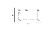
- the new learning correction value KGn calculated in this way is the learning correction corresponding to the current target fuel injection amount TQ and the current engine speed N among the learning correction values KG stored in the map of FIG. Stored as value KG.
- the calculation and storage of the new learning correction value corresponds to the update of the learning correction value.
- the instantaneous correction value is calculated based on the air-fuel ratio error ratio as described above, and the learning correction value is calculated from the map of FIG. 3 based on the target fuel injection amount TQ and the engine speed N at that time. KG is acquired.
- the control parameter correction value K is calculated by applying the learning correction value KG thus obtained and the instantaneous correction value calculated as described above to the above equation 3. Note that the initial value of the learning correction value KG stored in the map of FIG. 3 is “0”.
- the learning coefficient of the first embodiment is set to a larger value as the currently used learning correction value is larger.
- the learning coefficient is a value of “0” or more and a value of “1” or less.
- a command signal (in other words, an operation amount to be given to the fuel injection valve) to be given to the fuel injection valve in order to inject the fuel of the target fuel injection amount from the fuel injection valve based on the target fuel injection amount.
- a relationship between the target fuel injection amount and the command signal (for example, a conversion rule for converting the target fuel injection amount into the command signal) is obtained in advance, and this relationship is used during engine operation to target fuel injection.
- a command signal is calculated based on the quantity, and this command signal is given to the fuel injection valve.
- the operating characteristic of the fuel injection valve used when the above relationship is obtained is referred to as “the desired operating characteristic”
- the environment surrounding the fuel injection valve when the above relationship is obtained is referred to as “the desired operating characteristic”. If the operating characteristics of the fuel injector are the same as the desired operating characteristics and the environment surrounding the fuel injector is the same as the desired surrounding environment, the target fuel The command signal calculated based on the injection amount is given to the fuel injection valve, so that the fuel injection amount should match the target fuel injection amount.
- the operating characteristics of the fuel injection valve differ depending on the individual fuel injection valves, so that the operating characteristics of the fuel injection valve may deviate from the intended operating characteristics.
- the relationship between the output value of the air flow meter and the intake air amount (for example, a conversion rule for converting the output value of the air flow meter into the intake air amount). ) Is obtained in advance, and the intake air amount is calculated based on the output value of the air flow meter using this relationship during engine operation.
- the operating characteristics of the air flow meter used when the above relationship is determined are referred to as “initial operating characteristics”, and the environment surrounding the air flow meter when the above relationship is determined is referred to as “the desired ambient environment”.
- the intake air amount calculated using the above relationship Should match the actual intake air volume.
- the intake air amount calculated using the above relationship does not match the actual intake air amount.
- the air flow meter may be deteriorated, and its operating characteristics may deviate from the intended operating characteristics. Also in this case, the intake air amount calculated using the above relationship does not match the actual intake air amount.
- steady operational characteristic error of the air flow meter there is a steady error in the operational characteristics of the air flow meter with respect to the intended operational characteristics (hereinafter, this error is referred to as “steady operational characteristic error of the air flow meter”).
- the error of the detected air-fuel ratio (that is, the air-fuel ratio of the air-fuel mixture) with respect to the estimated air-fuel ratio (hereinafter, this error is referred to as “air-fuel ratio error”) includes the steady operation characteristic error of the fuel injection valve and the steady operation of the air flow meter.
- Air-fuel ratio error (hereinafter referred to as “steady air-fuel ratio error”) due to characteristic errors, and when the engine operating state is in a steady state, most of the air-fuel ratio error is a steady air-fuel ratio error. I can say that.
- the instantaneous correction value is sequentially calculated based on the air-fuel ratio error, and this instantaneous correction value is reflected in the newly calculated learning correction value. Therefore, the learning correction value has a function of eliminating the steady air-fuel ratio error. If the learning correction value is calculated more frequently, that is, if learning of the learning correction value is advanced, the learning correction value is a value that can completely eliminate the steady air-fuel ratio error (hereinafter, this value is referred to as a “learning value”). Gradually). Therefore, from the viewpoint of quickly converging the air-fuel ratio of the air-fuel mixture to the target air-fuel ratio, it is preferable that the learning correction value reaches the learning value early. That is, it is preferable to improve the learning speed of the learning correction value.
- a means for setting the learning coefficient to a relatively large value can be considered.
- this has the following disadvantages. That is, when the learning coefficient is fixed to a relatively large constant value, an excessively large instantaneous correction value (that is, an appropriate instantaneous correction that can converge the air-fuel ratio of the mixture to the estimated air-fuel ratio in a stable manner) When an instantaneous correction value that is far from the value is calculated, an excessively large learning addition value (that is, an appropriate learning correction value that can converge the air-fuel ratio of the mixture to the estimated air-fuel ratio in a stable manner) There is a possibility that a learning addition value that causes a far-off learning correction value to be calculated).
- an excessively large learning addition value is calculated, and a new learning correction value is calculated using the learning addition value (that is, the learning correction value is updated), an excessively large learning correction value (that is, the learning correction value is updated). Therefore, a learning correction value far from an appropriate learning correction value that can converge the air-fuel ratio of the air-fuel mixture to the estimated air-fuel ratio with a stable behavior is calculated. Then, the excessively large learning correction value is used for calculating the control parameter correction value, the target fuel injection amount is corrected by the control parameter correction value, and the reference EGR rate is obtained using the corrected target fuel injection amount.
- the air-fuel ratio of the air-fuel mixture changes while exhibiting unstable behavior. become. That is, the control of the air-fuel ratio of the air-fuel mixture becomes unstable. However, it is not preferable that the control of the air-fuel ratio of the air-fuel mixture is unstable. In addition, even if learning of the learning correction value proceeds while the control of the air-fuel ratio of the air-fuel mixture is unstable, the learning correction value cannot reach the learning value quickly (that is, learning of the learning correction value). Speed is not improved). However, if the learning coefficient is fixed to a relatively small constant value, the control of the air-fuel ratio of the air-fuel mixture becomes stable, but the learning correction value cannot reach the learning value quickly.
- the learning coefficient is set to a larger value as the currently used learning correction value is larger.
- a large learning correction value means that the learning correction value is close to the learning value, and if the learning correction value is close to the learning value, the possibility that an excessive instantaneous correction value is calculated is low. Therefore, even if the learning coefficient is calculated as a large value when the learning correction value is large, the possibility that an excessive learning addition value is calculated is low. Therefore, the learning correction value updated by the learning addition value calculated at this time is used for calculation of the fuel injection amount for acquiring the reference EGR rate, and the target based on the reference EGR rate acquired based on the fuel injection amount.
- the smaller the learning correction value currently used the smaller the learning coefficient is set.
- a small learning correction value means that the learning correction value is far from the learning value, and if the learning correction value is far from the learning value, there is a high possibility that an excessive instantaneous correction value is calculated. Therefore, if the learning coefficient is large, there is a high possibility that an excessive learning addition value is calculated.
- the learning correction value updated by the excessive learning addition value is used to calculate the fuel injection amount for acquiring the reference EGR rate, and the target is based on the reference EGR rate acquired based on the fuel injection amount.
- the learning coefficient is set to a smaller value as the learning correction value is smaller. Therefore, even if an excessive instantaneous correction value is calculated, the possibility that an excessive learning addition value is calculated is low. . Therefore, according to the first embodiment, it is sufficiently suppressed that the control of the air-fuel ratio of the air-fuel mixture becomes unstable, while the learning coefficient is set to a value corresponding to the learning correction value. The learning speed of the learning correction value is improved in an appropriate manner.
- a learning coefficient is set in accordance with the contribution of the currently used learning correction value to the newly calculated learning correction value, and thus the learning correction value contribution to the control parameter correction value. It is.
- the first embodiment has the advantage that it is possible to simultaneously ensure the stability of the control of the air-fuel ratio of the air-fuel mixture and improve the learning speed of the learning correction value.
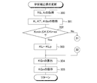
- FIG. 4 An example of this routine is shown in FIG. 4 is a routine executed at a predetermined time interval, that is, a routine executed at a predetermined calculation cycle.
- step 4 is started, first, at step 100, the current target fuel injection amount TQ and the current engine speed N are acquired.
- step 101 the instantaneous correction value KT calculated immediately before the execution of this step (that is, the past time closest to the execution time of this step) is acquired, and the target fuel injection acquired in step 100 is acquired.
- the learning correction value KGp is acquired from the map of FIG.
- the learning coefficient KL is set so that the larger the learning correction value KGp acquired in step 101 is, the larger the value is.
- a new learning correction value KGn is calculated by applying the instantaneous correction value KT and learning correction value KTp acquired in step 101 and the learning coefficient KL set in step 102 to the above equation 6.
- the new learning correction value KGn calculated at step 103 is stored as the learning correction value of the map of FIG. 3 corresponding to the target fuel injection amount TQ and the engine speed N acquired at step 100. The routine ends.
- the learning coefficient setting method of the first embodiment may be any method as long as the learning correction value used at that time is larger and a larger learning coefficient is set.
- the following method may be used. Can be adopted.
- an embodiment adopting this method hereinafter referred to as “second embodiment”.
- the learning coefficient (hereinafter referred to as the learning coefficient of the second embodiment corresponding to the learning coefficient of the first embodiment is referred to as the “first learning coefficient” in the instantaneous correction value calculated sequentially, as shown in the following Expression 7.
- 1 learning coefficient ", the details of which will be described later) (that is, a learning addition value) and a learning correction value that is currently used and a predetermined coefficient (hereinafter referred to as" second learning coefficient ").
- a new learning correction value is calculated by adding together a value obtained by multiplying by a coefficient called “coefficient” (details will be described later).
- Equation 7 “KGn” is “newly calculated learning correction value (ie, updated learning correction value)”, “KT” is “instantaneous correction value”, and “KL1” is “first learning value”. “KGp” is “the currently used learning correction value”, and “KL2” is the “second learning coefficient”.
- the new learning correction value KGn thus calculated is the current target fuel injection amount among the learning correction values KG stored in the map of FIG. It is stored as a learning correction value KG corresponding to TQ and the current engine speed N.
- an instantaneous correction value is calculated based on the air-fuel ratio error ratio, and a learning correction value KG is acquired from the map of FIG. 3 based on the target fuel injection amount TQ and the engine speed N at that time.
- the control parameter correction value K is calculated by applying the learning correction value KG thus obtained and the instantaneous correction value calculated as described above to the above equation 3.
- the absolute value of the instantaneous correction value calculated sequentially is multiplied by the calculation period (that is, the time period for executing the correction learning value calculation).
- the value obtained by multiplying the absolute value of the value obtained by adding the currently used learning correction value to the sequentially calculated instantaneous correction value and the value obtained by multiplying the reference value is calculated as a variable time constant.
- KV is a “variable time constant”
- KT is an “instantaneous correction value”
- TC is an “arithmetic period”
- KG is “the currently used learning correction”.
- Value "and” KB is the” reference value ".
- the reference value I is a value obtained in advance by experiments or the like so that the actual control parameter correction value falls within the allowable error range.
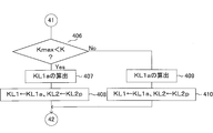
- the first learning coefficient is calculated by dividing the calculation cycle by a value obtained by adding a variable time constant to the calculation cycle, as shown in the following Expression 9.
- the second learning coefficient is calculated by dividing the variable time constant by a value obtained by adding the variable time constant to the calculation cycle.
- “KL1” is the “first learning coefficient”
- “KL2” is the “second learning coefficient”
- “TC” is the “calculation cycle”
- “KV” is “variable” Constant.
- KL1 TC / (TC + KV) (9)
- KL2 KV / (TC + KV) (10)
- the learning correction value reaches the learning value early from the viewpoint of quickly converging the air-fuel ratio of the air-fuel mixture to the target air-fuel ratio. That is, it is preferable to improve the learning speed of the learning correction value.
- a means for setting the first learning coefficient to a relatively large value can be considered.
- this has the following disadvantages. That is, when the first learning coefficient is fixed to a relatively large constant value, if an excessively large instantaneous correction value is calculated, an excessively large learning addition value may be calculated.
- an excessively large learning addition value is calculated and a new learning correction value is calculated using the learning addition value (that is, the learning correction value is updated), an excessively large learning correction value is calculated. Will be. Then, the excessively large learning correction value is used for calculating the control parameter correction value, the target fuel injection amount is corrected by the control parameter correction value, and the reference EGR rate is obtained using the corrected target fuel injection amount.
- the air-fuel ratio of the air-fuel mixture changes while exhibiting unstable behavior. become. That is, the control of the air-fuel ratio of the air-fuel mixture becomes unstable. However, it is not preferable that the control of the air-fuel ratio of the air-fuel mixture is unstable. In addition, even if learning of the learning correction value proceeds while the control of the air-fuel ratio of the air-fuel mixture is unstable, the learning correction value cannot reach the learning value quickly (that is, learning of the learning correction value). Speed is not improved). However, if the first learning coefficient is fixed to a relatively small constant value, the control of the air-fuel ratio of the air-fuel mixture becomes stable, but the learning correction value cannot reach the learning value quickly.
- the variable time constant KV is calculated as a smaller value as the learning correction value KG is larger, as can be seen from Equation 8 above.
- the first learning coefficient KL1 is calculated as a larger value as the variable time constant KV is smaller. That is, the larger the learning correction value KG, the larger the first learning coefficient KL1 is calculated.
- a large learning correction value means that the learning correction value is close to the learning value, and if the learning correction value is close to the learning value, the possibility that an excessive instantaneous correction value is calculated is low. Therefore, even if the first learning coefficient is calculated as a large value when the learning correction value is large, the possibility that an excessive learning addition value is calculated is low.
- the learning correction value updated by the learning addition value calculated at this time is used for calculation of the fuel injection amount for acquiring the reference EGR rate, and the target based on the reference EGR rate acquired based on the fuel injection amount. Even if the EGR rate is set and this target EGR rate is used to control the operating state of the EGR control valve (that is, the EGR control valve opening), it is sufficient that the control of the air-fuel ratio of the air-fuel mixture becomes unstable. On the other hand, since the first learning coefficient is large, the learning speed of the learning correction value is sufficiently improved.
- the smaller the learning correction value the smaller the first learning coefficient is calculated.
- a small learning correction value means that the learning correction value is far from the learning value, and if the learning correction value is far from the learning value, there is a high possibility that an excessive instantaneous correction value is calculated. Therefore, if the first learning coefficient is large, there is a high possibility that an excessive learning addition value is calculated.
- the learning correction value updated by the excessive learning addition value is used to calculate the fuel injection amount for acquiring the reference EGR rate, and the target is based on the reference EGR rate acquired based on the fuel injection amount.
- the control of the air-fuel ratio of the air-fuel mixture becomes unstable.
- the first learning coefficient is calculated as a smaller value as the learning correction value is smaller, an excessive learning addition value may be calculated even if an excessive instantaneous correction value is calculated. Is low. Therefore, according to the second embodiment, it is sufficiently suppressed that the control of the air-fuel ratio of the air-fuel mixture becomes unstable, while the first learning coefficient is set to a value corresponding to the learning correction value. Therefore, the learning speed of the learning correction value is improved in an appropriate manner.
- the contribution of the currently used learning correction value to the newly calculated learning correction value and thus the contribution of the learning correction value to the control parameter correction value.
- the first learning coefficient corresponding to is calculated.
- the second embodiment has the advantage that it is possible to simultaneously ensure the stability of the control of the air-fuel ratio of the air-fuel mixture and improve the learning speed of the learning correction value.
- variable time constant KV calculated from 8 is determined whether the variable time constant KV calculated from 8 is larger than the upper limit value, and when the variable time constant calculated from the above equation 8 is larger than the upper limit value, the upper limit value is set as the first learning coefficient.
- it may be adopted as a variable time constant that is actually used for calculating the second learning coefficient. That is, the variable time constant calculated from Equation 8 may be guarded to the upper limit value.
- variable time constant calculated from the above equation 8 is less than or equal to the upper limit value
- the calculated variable time constant is adopted as the variable time constant actually used for calculating the first learning coefficient and the second learning coefficient. That's fine.
- the variable time constant KV calculated from Expression 8 is smaller than the lower limit value.
- variable time constant calculated from Equation 8 may be guarded to the lower limit value.
- the calculated variable time constant is adopted as the variable time constant actually used for calculating the first learning coefficient and the second learning coefficient. That's fine.
- the second learning coefficient may be fixed to a constant value.
- the first learning coefficient as large as possible is calculated on condition that the control parameter correction value is within the allowable correction value range. It is preferable to set a reference value.
- the routine shown in FIG. 5 is a routine executed at a predetermined time interval, that is, a routine executed at a predetermined calculation cycle.
- step 5 is started, first, at step 200, the current target fuel injection amount TQ and the current engine speed N are acquired.
- step 201 the instantaneous correction value KT calculated immediately before the execution of this step (that is, the past time closest to the execution time of this step) is acquired, and the target fuel injection acquired in step 200 is acquired.
- the learning correction value KGp is acquired from the map of FIG.
- the variable time constant KV is calculated by applying the instantaneous correction value KT and the learning correction value KGp acquired in step 201 to the above equation 8.
- step 203 the first learning coefficient KL1 is calculated by applying the variable time constant KV calculated in step 202 to the above equation 9, and the variable time constant KV calculated in step 202 is calculated using the equation 10 above. Is applied to the second learning coefficient KL2.
- step 204 the instantaneous correction value KT and learning correction value KTp acquired in step 201 and the first learning coefficient KL1 and the second learning coefficient KL2 calculated in step 203 are applied to the above equation 7 to A correct learning correction value KGn is calculated.
- step 205 the new learning correction value KGn calculated at step 204 is stored as the learning correction value of the map of FIG. 3 corresponding to the target fuel injection amount TQ and the engine speed N acquired at step 200. The routine ends.
- the control parameter correction value is calculated using the newly calculated learning correction value, and the target fuel injection amount and the engine speed corrected by the control parameter correction value are calculated.
- the reference EGR rate corresponding to the number is acquired from the map of FIG. 2C, the acquired reference EGR rate is set as the target EGR rate, and the operation state of the EGR control valve according to the set target EGR rate ( That is, when the opening degree of the EGR control valve is controlled, the learning coefficient is set depending on whether or not the air-fuel ratio of the air-fuel mixture can be controlled with a stable behavior toward the estimated air-fuel ratio. It is an idea.
- the target EGR rate is set as in the first embodiment. That is, as shown in the above equation 2, the fuel injection amount obtained by multiplying the target fuel injection amount set during engine operation by the control parameter correction value is calculated from the map of FIG.
- the reference EGR rate is obtained from the map shown in FIG. 2C as the engine speed for obtaining the reference EGR rate from the map shown in FIG. 2C. Is done. Then, the acquired reference EGR rate is set as the target EGR rate.
- control parameter correction value is calculated as in the first embodiment. That is, as shown in Equation 3, the control parameter correction value K is calculated by adding the instantaneous correction value KT, the learning correction value KG, and “1”.
- the instantaneous correction value is calculated as in the first embodiment. That is, as shown in the above equation 4, a value (that is, an air-fuel ratio error ratio) Raf obtained by dividing the estimated air-fuel ratio AFe by the detected air-fuel ratio AFd is calculated.
- the estimated air-fuel ratio AFe is obtained by dividing the intake air amount Ga by a value obtained by multiplying the target fuel injection amount TQ by the control parameter correction value K as shown in the above equation 5. Value.
- the reference EGR rate is acquired so that the air-fuel ratio error ratio becomes “1”.
- the control parameter correction value that can set the air-fuel ratio error ratio to “1” by correcting the control parameter correction value currently used for correcting the target fuel injection amount for calculating the fuel injection amount used for The correction value is calculated as an instantaneous correction value.
- the learning correction value is calculated as in the first embodiment. That is, as shown in the above equation 6, the learning addition value obtained by multiplying the successively calculated instantaneous correction value KT by the learning coefficient KL and the currently used learning correction value KGp are added together. A new learning correction value KGn is calculated.
- the new learning correction value calculated in this way is the current target fuel injection amount and the current engine speed among the learning correction values stored in the map of FIG. Stored as the corresponding learning correction value.
- an instantaneous correction value is calculated based on the air-fuel ratio error ratio as described above, and a learning correction value is obtained from the map of FIG. 3 based on the target fuel injection amount and engine speed at that time. Is done.
- the control parameter correction value is calculated by applying the learning correction value thus obtained and the instantaneous correction value calculated as described above to Equation 3 above.
- the learning coefficient of the third embodiment will be described.
- a prescribed learning coefficient is preset.
- the learning correction value is updated using the prescribed learning coefficient
- the control parameter correction value is calculated using the updated learning correction value, and is corrected by the calculated control parameter correction value.
- the reference EGR rate corresponding to the target fuel injection amount and the engine speed is acquired from the map of FIG. 2C, the acquired reference EGR rate is set as the target EGR rate, and the set target EGR rate is set.
- Range of the control parameter correction value in which the air-fuel ratio of the air-fuel mixture can be controlled in a stable manner toward the estimated air-fuel ratio when the operating state of the EGR control valve (that is, the EGR control valve opening) is controlled according to (Hereinafter, this range is referred to as “allowable correction value range”) is obtained in advance by experiments or the like.
- control parameter correction value is within the allowable correction value range.
- the specified learning coefficient is employed as it is as the learning coefficient actually used for updating the learning correction value.
- the control parameter correction value when it is determined that the control parameter correction value is not within the allowable correction value range, whether or not the control parameter correction value is larger than the upper limit value of the allowable correction value range (hereinafter, this upper limit value is referred to as “allowable upper limit value”). Is determined.
- a learning coefficient that can match the control parameter correction value with the allowable upper limit value is used as a learning coefficient that is actually used for updating the learning correction value.
- the specified learning coefficient is corrected so that the control parameter correction value matches the allowable upper limit value, and this corrected learning coefficient is used as the learning correction value. It is adopted as a learning coefficient that is actually used for updating.
- the control parameter correction value is not larger than the allowable upper limit value, that is, the control parameter correction value is smaller than the lower limit value of the allowable correction value range (hereinafter, this lower limit value is referred to as “allowable lower limit value”).
- this lower limit value is referred to as “allowable lower limit value”.
- a learning coefficient that can make the control parameter correction value coincide with the allowable lower limit value is adopted as a learning coefficient that is actually used for updating the learning correction value.
- the control parameter correction value is smaller than the allowable lower limit value, the specified learning coefficient is corrected so that the control parameter correction value matches the allowable lower limit value, and this corrected learning coefficient is actually used for updating the learning correction value. Adopted as a learning coefficient.
- the control parameter correction value when the control parameter correction value is not within the allowable correction value range, that is, when the learning correction value is updated using a specified learning coefficient, the air-fuel ratio of the mixture is changed to the estimated air-fuel ratio.
- the specified learning coefficient is corrected so that the control parameter correction value is within the allowable correction value range, and the corrected learning coefficient is used to update the learning correction value. It is adopted as a learning coefficient that is actually used. More specifically, when the control parameter correction value is larger than the allowable upper limit value and therefore the control parameter correction value is not within the allowable correction value range, the specified learning is performed so that the control parameter correction value matches the allowable upper limit value.
- the coefficient is corrected, and the corrected learning coefficient is adopted as a learning coefficient actually used for updating the learning correction value.
- the air-fuel ratio of the air-fuel mixture can be controlled with a stable behavior toward the estimated air-fuel ratio. That is, stable control of the air-fuel ratio of the air-fuel mixture is ensured.
- the control parameter correction value is smaller than the allowable lower limit value, and therefore the control parameter correction value is not within the allowable correction value range
- the specified learning coefficient is corrected so that the control parameter correction value matches the allowable lower limit value.
- the corrected learning coefficient is employed as a learning coefficient that is actually used for updating the learning correction value.
- the air-fuel ratio of the air-fuel mixture can be controlled with a stable behavior toward the estimated air-fuel ratio. That is, the stability of the control of the air-fuel ratio of the air-fuel mixture is ensured.
- the specified learning coefficient is corrected only when the control parameter correction value is not within the allowable correction value range. That is, the specified learning coefficient is corrected only when the control of the air-fuel ratio of the air-fuel mixture is not ensured. Therefore, as a whole, the learning coefficient actually used for updating the learning correction value is set to a learning coefficient that can maintain the learning speed of the learning correction value high. For this reason, according to the third embodiment, the learning speed of the learning correction value is improved as a whole.
- the learning coefficient according to the contribution of the currently used learning correction value to the newly calculated learning correction value, and hence the learning correction value contribution to the control parameter correction value, is calculated. It is.
- the third embodiment has an advantage that it is possible to simultaneously achieve the stability of the control of the air-fuel ratio of the air-fuel mixture and the improvement of the learning speed of the learning correction value.
- the specified learning coefficient when the control parameter correction value is larger than the allowable upper limit value, the specified learning coefficient is corrected so that the control parameter correction value matches the allowable upper limit value.
- the control parameter The prescribed learning coefficient may be corrected so that the correction value is a value within the allowable correction value range.
- the specified learning coefficient when the control parameter correction value is smaller than the allowable lower limit value, the specified learning coefficient is corrected so that the control parameter correction value matches the allowable lower limit value.
- control parameter correction value when the control parameter correction value is smaller than the allowable lower limit value, the control parameter The prescribed learning coefficient may be corrected so that the correction value is a value within the allowable correction value range.
- the specified learning coefficient is corrected only when the control parameter correction value is not within the allowable correction value range.
- the learning coefficient may be corrected within a range in which the control parameter correction value is within the allowable correction value. In this case, from the viewpoint of improving the learning speed of the learning correction value, when the control parameter correction value is within the allowable correction value range, the largest learning coefficient that can fit the control parameter correction value within the allowable correction value range. It is preferable to correct the specified learning coefficient so as to be the learning coefficient.
- routines that are executed at predetermined time intervals that is, routines that are executed at a predetermined calculation cycle.
- step 300 the current target fuel injection amount TQ and the current engine speed N are acquired.
- step 301 the control parameter correction value K and the instantaneous correction value KT calculated immediately before the execution of this step (that is, the past time closest to the execution time of this step) are acquired. Based on the acquired target fuel injection amount TQ and the engine speed N, a learning correction value KGp is acquired from the map of FIG.
- step 302 it is determined whether or not the control parameter correction value K acquired in step 301 is within an allowable correction value range (Kmin ⁇ K ⁇ Kmax).
- the routine proceeds to step 303.
- the routine proceeds to step 306 in FIG.
- step 302 When it is determined in step 302 that the control parameter correction value K is within the allowable correction value range and the routine proceeds to step 303, the specified learning coefficient KL1p is input to the learning coefficient KL1, and the routine proceeds to step 304.
- step 306 the control parameter correction value K acquired in step 301 is the upper limit value of the allowable correction value range. It is determined whether or not it is larger than Kmax (Kmax ⁇ K). Here, when it is determined that Kmax ⁇ K, the routine proceeds to step 307. On the other hand, if it is determined that Kmax ⁇ K is not satisfied, the routine proceeds to step 309.
- step 306 When it is determined in step 306 that Kmax ⁇ K and the routine proceeds to step 307, the specified learning coefficient is corrected so that the control parameter correction value K acquired in step 301 can be made to coincide with the upper limit value Kmax. Thus, the corrected learning coefficient KLa is calculated.
- step 308 the corrected learning coefficient KLa calculated at step 307 is input to the learning coefficient KL, and the routine proceeds to step 304.
- step 306 If it is determined in step 306 that Kmax ⁇ K is not satisfied, that is, if the control parameter correction value K acquired in step 301 is smaller than the lower limit value Kmin of the allowable correction value range and the routine proceeds to step 309, the control parameter correction value K is acquired in step 301
- the corrected learning coefficient KLa is calculated by correcting the specified learning coefficient so that the control parameter correction value K thus made can be matched with the lower limit value Kmin.
- step 310 the corrected learning coefficient KLa calculated at step 309 is input to the learning coefficient KL, and the routine proceeds to step 304.
- a new learning correction value KGn is calculated. More specifically, when the routine proceeds from step 303 to step 304, the learning coefficient KL to which the specified learning coefficient KLp is input in step 303 and the instantaneous correction value KT and the learning correction value acquired in step 301 are stored. A new learning correction value KGn is calculated by applying KGp to Equation 6 above. When the routine proceeds from step 308 to step 304, the learning coefficient KL to which the corrected learning coefficient KLa is input in step 308 and the instantaneous correction value KT and the learning correction value KGp acquired in step 301 are expressed by the following equation (6). By applying, a new learning correction value KGn is calculated.
- step 304 the learning coefficient KL to which the corrected learning coefficient KLa is input in step 310 and the instantaneous correction value KT and the learning correction value KGp acquired in step 301 are expressed by the above equation 6.
- a new learning correction value KGn is calculated.
- step 305 the new learning correction value KGn calculated at step 304 is stored in the electronic control unit corresponding to the target fuel injection amount TQ and the engine speed N acquired at step 300.
- a control parameter correction value is calculated using a newly calculated learning correction value, and the target fuel injection amount and the engine speed corrected by the control parameter correction value are calculated.
- the reference EGR rate corresponding to the number is acquired from the map of FIG. 2C, the acquired reference EGR rate is set as the target EGR rate, and the operation state of the EGR control valve according to the set target EGR rate ( That is, when the opening degree of the EGR control valve is controlled, the first learning coefficient is set according to whether or not the air-fuel ratio of the air-fuel mixture can be controlled with a stable behavior toward the estimated air-fuel ratio.
- the target EGR rate is set as in the second embodiment. That is, as shown in the above equation 2, the fuel injection amount obtained by multiplying the target fuel injection amount set during engine operation by the control parameter correction value is calculated from the map of FIG.
- the reference EGR rate is obtained from the map shown in FIG. 2C as the engine speed for obtaining the reference EGR rate from the map shown in FIG. 2C. Is done. Then, the acquired reference EGR rate is set as the target EGR rate.
- control parameter correction value is calculated as in the second embodiment. That is, as shown in Equation 3, the control parameter correction value K is calculated by adding the instantaneous correction value KT, the learning correction value KG, and “1”.
- the instantaneous correction value is calculated as in the second embodiment. That is, as shown in the above equation 4, a value (that is, an air-fuel ratio error ratio) Raf obtained by dividing the estimated air-fuel ratio AFe by the detected air-fuel ratio AFd is calculated.
- the estimated air-fuel ratio AFe is obtained by dividing the intake air amount Ga by a value obtained by multiplying the target fuel injection amount TQ by the control parameter correction value K as shown in the above equation 5. Value.
- the reference EGR rate is acquired so that the air-fuel ratio error ratio becomes “1”.
- the control parameter correction value that can set the air-fuel ratio error ratio to “1” by correcting the control parameter correction value currently used for correcting the target fuel injection amount for calculating the fuel injection amount used for The correction value is calculated as an instantaneous correction value.
- the learning correction value is calculated as in the second embodiment. That is, as shown in the above equation 7, the learning addition value obtained by multiplying the sequentially calculated instantaneous correction value KT by the first learning coefficient KL1 and the currently used learning correction value KGp are subjected to the second learning.
- a new learning correction value KGn is calculated by adding the value obtained by multiplying the coefficient KL2.
- the new learning correction value thus calculated is the current target fuel injection amount and the current learning correction value stored in the map of FIG. Is stored as a learning correction value corresponding to the engine speed.
- an instantaneous correction value is calculated based on the air-fuel ratio error ratio, and a learning correction value is acquired from the map of FIG. 3 based on the target fuel injection amount and engine speed at that time.
- the control parameter correction value is calculated by applying the learning correction value thus obtained and the instantaneous correction value calculated as described above to Equation 3 above.
- a value obtained by dividing the calculation cycle by a value obtained by adding a fixed time constant to the calculation cycle is set in advance as a prescribed first learning coefficient.
- a value obtained by dividing the fixed time constant by a value obtained by adding the fixed time constant to the calculation cycle is preset as a prescribed second learning coefficient.
- KL1 is the “specified first learning coefficient”
- KL2 is the “specified second learning coefficient”
- TC is the “calculation cycle”
- KF Is the “fixed time constant”.
- the fixed time constant is a constant value regardless of the value of the learning correction value, unlike the variable time constant of the first embodiment.
- KL1 TC / (TC + KF) (11)
- KL2 KF / (TC + KF) (12)
- the learning correction value is updated using the predetermined first learning coefficient and the predetermined second learning coefficient set in advance as described above, and thus the updated learning correction value is used.
- a control parameter correction value is calculated, and a reference EGR rate corresponding to the target fuel injection amount and the engine speed corrected by the calculated control parameter correction value is acquired from the map of FIG.
- the acquired reference EGR rate is set to the target EGR rate, and the operation state of the EGR control valve (that is, the EGR control valve opening) is controlled according to the set target EGR rate, the air-fuel ratio of the mixture is changed.
- a range of control parameter correction values that can be controlled with a stable behavior toward the estimated air-fuel ratio hereinafter, this range is referred to as “allowable correction value range” is obtained in advance by experiments or the like.
- the prescribed first learning coefficient is employed as it is as the first learning coefficient that is actually used for updating the learning correction value.
- the control parameter correction value when it is determined that the control parameter correction value is not within the allowable correction value range, whether or not the control parameter correction value is larger than the upper limit value of the allowable correction value range (hereinafter, this upper limit value is referred to as “allowable upper limit value”). Is determined.
- the first learning coefficient that can match the control parameter correction value with the allowable upper limit value is actually used for updating the learning correction value.
- One learning coefficient is adopted. That is, when it is determined that the control parameter correction value is larger than the allowable upper limit value, the specified first learning coefficient is corrected so that the control parameter correction value matches the allowable upper limit value, and the corrected first learning coefficient is corrected. Is adopted as the first learning coefficient that is actually used for updating the learning correction value.
- the control parameter correction value when it is determined that the control parameter correction value is not larger than the allowable upper limit value, that is, the control parameter correction value is smaller than the lower limit value of the allowable correction value range (hereinafter, this lower limit value is referred to as “allowable lower limit value”).
- the first learning coefficient that can match the control parameter correction value with the allowable lower limit value is employed as the first learning coefficient that is actually used for updating the learning correction value. That is, when the control parameter correction value is smaller than the allowable lower limit value, the specified first learning coefficient is corrected so that the control parameter correction value matches the allowable lower limit value, and the corrected first learning coefficient is used as the learning correction value. This is employed as the first learning coefficient that is actually used for updating.
- the specified second learning coefficient is used as it is as the second learning coefficient that is actually used for updating the learning correction value. Adopted.
- the air-fuel ratio of the air-fuel mixture is estimated.
- the specified first learning coefficient is corrected so that the control parameter correction value is within the allowable correction value range, and the corrected first learning coefficient is It is adopted as the first learning coefficient that is actually used for updating the learning correction value. More specifically, when the control parameter correction value is larger than the allowable upper limit value, and therefore, when the control parameter correction value is not within the allowable correction value range, the control parameter correction value is set to match the allowable upper limit value.
- One learning coefficient is corrected, and the corrected first learning coefficient is adopted as the first learning coefficient that is actually used for updating the learning correction value.
- the air-fuel ratio of the air-fuel mixture can be controlled with a stable behavior toward the estimated air-fuel ratio. That is, stable control of the air-fuel ratio of the air-fuel mixture is ensured.
- the specified first learning coefficient is set so that the control parameter correction value matches the allowable lower limit value.
- the corrected first learning coefficient is adopted as the first learning coefficient that is actually used for updating the learning correction value.
- the air-fuel ratio of the air-fuel mixture can be controlled with a stable behavior toward the estimated air-fuel ratio. That is, the stability of the control of the air-fuel ratio of the air-fuel mixture is ensured.
- the specified first learning coefficient is corrected only when the control parameter correction value is not within the allowable correction value range. That is, the specified first learning coefficient is corrected only when the control of the air-fuel ratio of the air-fuel mixture is not ensured. Accordingly, as a whole, the first learning coefficient actually used for updating the learning correction value is set to the first learning coefficient that can maintain the learning speed of the learning correction value high. For this reason, according to the fourth embodiment, the learning speed of the learning correction value is improved as a whole.
- the first learning coefficient corresponding to the contribution of the currently used learning correction value to the newly calculated learning correction value, and hence the contribution of the learning correction value to the control parameter correction value, is obtained. It is calculated.
- the fourth embodiment has an advantage that it is possible to simultaneously achieve the stability of control of the air-fuel ratio of the air-fuel mixture and the improvement of the learning speed of the learning correction value.
- the specified first learning coefficient is corrected so that the control parameter correction value matches the allowable upper limit value.
- the control parameter The prescribed first learning coefficient may be corrected so that the correction value falls within the allowable correction value range.
- the specified first learning coefficient is corrected so that the control parameter correction value matches the allowable lower limit value.
- control parameter correction value when the control parameter correction value is smaller than the allowable lower limit value, the control parameter The prescribed first learning coefficient may be corrected so that the correction value falls within the allowable correction value range.
- the specified first learning coefficient is corrected when the control parameter correction value is larger than the allowable upper limit value.
- the specified second learning coefficient may be corrected when the control parameter correction value is larger than the allowable upper limit value.
- the specified first learning coefficient and the specified second learning coefficient are corrected so that the control parameter correction value matches the allowable upper limit value.
- the corrected first learning coefficient and second learning coefficient are respectively employed as the first learning coefficient and the second learning coefficient that are actually used for updating the learning correction value.
- the specified first learning coefficient and the specified second learning coefficient are corrected so that the control parameter correction value matches the allowable lower limit value.
- the 1 learning coefficient and the second learning coefficient are respectively employed as the first learning coefficient and the second learning coefficient that are actually used for updating the learning correction value.
- the specified first learning coefficient is corrected only when the control parameter correction value is not within the allowable correction value range.
- the first learning coefficient may be corrected within a range in which the control parameter correction value is within the allowable correction value.
- the control parameter correction value when the control parameter correction value is within the allowable correction value range, the first learning coefficient that can fit the control parameter correction value within the allowable correction value range. It is preferable to correct the prescribed first learning coefficient so as to be the largest first learning coefficient.
- routines of FIGS. 8 and 9 are routines executed at predetermined time intervals, that is, routines executed at a predetermined calculation cycle.
- step 400 the current target fuel injection amount TQ and the current engine speed N are acquired.
- step 401 the control parameter correction value K and the instantaneous correction value KT calculated immediately before the execution of this step (that is, the past time closest to the execution time of this step) are acquired. Based on the acquired target fuel injection amount TQ and the engine speed N, a learning correction value KGp is acquired from the map of FIG.
- step 402 it is determined whether or not the control parameter correction value K acquired at step 401 is within the allowable correction value range (Kmin ⁇ K ⁇ Kmax).
- the routine proceeds to step 403.
- the routine proceeds to step 406 in FIG.
- step 403 When it is determined in step 402 that the control parameter correction value K is within the allowable correction value range and the routine proceeds to step 403, the specified first learning coefficient KL1p is input to the first learning coefficient KL1 and the specified first learning coefficient KL1.
- the second learning coefficient KL2p is input to the second learning coefficient KL2, and the routine proceeds to step 404.
- step 406 the control parameter correction value K acquired in step 401 is the upper limit value of the allowable correction value range. It is determined whether or not it is larger than Kmax (Kmax ⁇ K).
- Kmax ⁇ K the routine proceeds to step 407.
- Kmax ⁇ K the routine proceeds to step 409.
- step 406 When it is determined in step 406 that Kmax ⁇ K and the routine proceeds to step 407, the prescribed first learning coefficient is set so that the control parameter correction value K acquired in step 401 can be made to coincide with the upper limit value Kmax. As a result of the correction, the corrected first learning coefficient KL1a is calculated.
- step 408 the corrected first learning coefficient KL1a calculated in step 407 is input to the first learning coefficient KL1, and the specified second learning coefficient KL2p is input to the second learning coefficient KL2, and the routine is stepped. Proceed to 404.
- step 406 If it is determined in step 406 that Kmax ⁇ K is not satisfied, that is, the control parameter correction value K acquired in step 401 is smaller than the lower limit value Kmin of the allowable correction value range, and the routine proceeds to step 409, the control parameter correction value K is acquired in step 401.
- the corrected first learning coefficient KL1a is calculated by correcting the prescribed first learning coefficient so that the control parameter correction value K thus made can be matched with the lower limit value Kmin.
- step 410 the corrected first learning coefficient KL1a calculated in step 409 is input to the first learning coefficient KL1, and the prescribed second learning coefficient KL2p is input to the second learning coefficient KL2, and the routine is stepped. Proceed to 404.
- a new learning correction value KGn is calculated. More specifically, when the routine proceeds from step 403 to step 404, the first learning coefficient KL1 to which the specified first learning coefficient KL1p is input in step 403 and the second learning coefficient KL2p specified in step 403 are input. A new learning correction value KGn is calculated by applying the second learning coefficient KL2 to which is input and the instantaneous correction value KT and the learning correction value KGp acquired in step 401 to the above equation 7. When the routine proceeds from step 408 to step 404, the second learning in which the first learning coefficient KL1 to which the corrected first learning coefficient KL1a is input in step 408 and the second learning coefficient KL1p specified in step 408 is input.
- a new learning correction value KGn is calculated by applying the coefficient KL2 and the instantaneous correction value KT and learning correction value KGp acquired in step 401 to the above equation 7.
- the routine proceeds from step 410 to step 404, the second learning in which the corrected first learning coefficient KL1a is input in step 410 and the second learning coefficient KL1p specified in step 410 is input.
- a new learning correction value KGn is calculated by applying the coefficient KL2 and the instantaneous correction value KT and learning correction value KGp acquired in step 401 to the above equation 7.
- the new learning correction value KGn calculated at step 404 is stored in the electronic control unit corresponding to the target fuel injection amount TQ and the engine speed N acquired at step 400.
- the above-described embodiment is an embodiment in which the present invention is applied to a control device that executes control for matching the air-fuel ratio of the air-fuel mixture with the estimated air-fuel ratio by controlling the EGR rate with the EGR control valve.
- the present invention can also be applied to a control device that executes control for matching the air-fuel ratio of the air-fuel mixture to the estimated air-fuel ratio by controlling the intake air amount with a throttle valve in an internal combustion engine that does not include an EGR device.
- an embodiment in which the technical idea of the first embodiment is applied to such a control device hereinafter referred to as “fifth embodiment” will be described.
- the structure of 5th Embodiment which is not mentioned in the following description is the same as the structure of 1st Embodiment.
- FIG. 10 shows an internal combustion engine to which the control device of the fifth embodiment is applied.
- the internal combustion engine shown in FIG. 10 is the same as the internal combustion engine shown in FIG. 1 except that it does not include an EGR device. Further, since the internal combustion engine to which the control device of the fifth embodiment is applied does not include an EGR device, unlike the first embodiment, the EGR control valve is not controlled.
- an optimal fuel injection amount is obtained in advance by experiments or the like according to the depression amount of the accelerator pedal.
- the obtained fuel injection amount is stored in the electronic control unit as a reference fuel injection amount Qb in the form of a map of a function of the accelerator pedal depression amount Dac as shown in FIG.
- the reference fuel injection amount Qb corresponding to the accelerator pedal depression amount Dac at that time is acquired from the map of FIG. 11A, and the acquired reference fuel injection amount Qb becomes the target fuel injection amount. Is set.
- a command signal is supplied from the electronic control unit to the fuel injection valve so that the fuel of the target fuel injection amount thus set is injected from the fuel injection valve.
- the reference fuel injection amount Qb increases as the accelerator pedal depression amount Dac increases.
- the operating state of the internal combustion engine shown in FIG. 10 is maintained in a steady operation state (that is, a state in which the fuel injection amount and the engine speed are kept constant) and the environment surrounding the internal combustion engine.
- Parameters that affect the engine operating state for example, atmospheric pressure, atmospheric temperature, internal combustion engine temperature, etc., hereinafter referred to as “environmental parameters” have a specific value.
- an appropriate throttle valve opening corresponding to the fuel injection amount and the engine speed is obtained in advance by experiments or the like. Then, as shown in FIG.
- the obtained throttle valve opening is set as a reference throttle valve opening Dthb in the form of a map of a function of the fuel injection amount Q and the engine speed N. Is remembered.
- the reference throttle valve opening Dthb increases as the fuel injection amount Q increases, and the reference throttle valve opening Dthb increases as the engine speed N increases.
- the fuel injection amount obtained by multiplying the target fuel injection amount set during engine operation by the control parameter correction value is set as a reference throttle from the map of FIG.
- the fuel injection amount Q for obtaining the valve opening degree Dthb is set as the engine speed N for obtaining the reference throttle valve opening degree Dthb from the map of FIG. )
- the fuel injection amount obtained by correcting the target fuel injection amount set during engine operation with the control parameter correction value is used to obtain the reference throttle valve opening Dthb from the map of FIG.
- “Q” is “a fuel supply amount used for obtaining the reference throttle valve opening from the map of FIG. 11B”
- TQ is a “target fuel injection amount”
- “K” is a “control parameter correction value”.
- the reference throttle valve opening Dthb acquired from the map of FIG. 11B is set as the target throttle valve opening.
- a control signal for driving the throttle valve actuator is supplied from the electronic control device so as to drive the throttle valve so that the throttle valve opening becomes the target throttle valve opening TDth thus set.
- control parameter correction value is calculated according to Equation 3 as in the first embodiment.
- the air-fuel ratio error ratio is calculated according to Equation 4 as in the first embodiment.
- the reference throttle valve opening degree is set so that the air-fuel ratio error ratio becomes “1”.
- Parameter correction capable of setting the air-fuel ratio error ratio to "1” by correcting the control parameter correction value currently used for correcting the target fuel injection amount for calculating the fuel injection amount used for obtaining A correction value for the value is calculated as an instantaneous correction value.
- the air-fuel ratio error ratio is set to “1” by correcting the current target fuel injection amount on the assumption that the target fuel injection amount is corrected by the control parameter correction value currently used for correcting the fuel supply amount.
- a correction value for the target fuel injection amount that can be calculated is calculated as an instantaneous correction value.
- a new learning correction value is calculated according to Equation 6 as in the first embodiment.
- the new learning correction value KGn calculated in this way is the learning correction corresponding to the current target fuel injection amount TQ and the current engine speed N among the learning correction values KG stored in the map of FIG. Stored as value KG.
- the calculation and storage of the new learning correction value corresponds to the update of the learning correction value.
- the instantaneous correction value is calculated based on the air-fuel ratio error ratio as described above, and the learning correction value is calculated from the map of FIG. 12 based on the target fuel injection amount TQ and the engine speed N at that time.
- KG is acquired.
- the control parameter correction value K is calculated by applying the learning correction value KG thus obtained and the instantaneous correction value calculated as described above to Equation 3. Note that the initial value of the learning correction value KG stored in the map of FIG. 12 is “0”.
- the learning coefficient of the fifth embodiment is set to a larger value as the learning correction value used in the current actuator is larger.
- the learning coefficient is a value of “0” or more and a value of “1” or less.
- the learning coefficient is set to a larger value as the currently used learning correction value is larger. That is, a learning coefficient is set in accordance with the contribution degree of the currently used learning correction value to the newly calculated learning correction value, and consequently the contribution degree of the learning correction value to the control parameter correction value.
- the fifth embodiment simultaneously ensures the stability of the air-fuel ratio control of the air-fuel mixture and improves the learning speed of the learning correction value. There is an advantage that can be achieved.
- the second embodiment of the present invention is a control device that executes control for matching the air-fuel ratio of the air-fuel mixture to the estimated air-fuel ratio by controlling the intake air amount with a throttle valve in an internal combustion engine that does not include an EGR device.
- the technical idea of the third embodiment or the fourth embodiment can also be applied.
- routine shown in FIG. 4 can be adopted as a routine for executing the update of the learning correction value of the fifth embodiment.
- a control device that executes control for making the air-fuel ratio of the air-fuel mixture coincide with the estimated air-fuel ratio by controlling the intake air amount through control of the EGR rate by the EGR control valve. It is an embodiment to which the present invention is applied. However, the present invention can also be applied to a control device that executes control of the intake air amount using a throttle valve in addition to control of the intake air amount via control of the EGR rate using the EGR control valve.
- control parameter correction values in the first to fourth embodiments are correction values for correcting the target fuel injection amount in order to obtain the fuel injection amount for obtaining the reference EGR rate.
- this control parameter correction value may be a correction value for correcting the reference EGR rate acquired using the target fuel injection amount as the fuel injection amount for acquiring the reference EGR rate as it is.
- the reference EGR rate corrected by the control parameter correction value is set as the target EGR rate.
- control parameter correction value of the fifth embodiment is a correction value for correcting the target fuel injection amount in order to obtain the fuel injection amount for obtaining the reference throttle valve opening.
- control parameter correction value may be a correction value for correcting the reference throttle valve opening acquired using the target fuel injection amount as the fuel injection amount for acquiring the reference throttle valve opening as it is. In this case, the reference throttle valve opening corrected by the control parameter is set to the target throttle valve opening.
- the instantaneous correction value is a so-called PI term.
- the above-described embodiment is an embodiment in which the present invention is applied to a compression ignition type internal combustion engine, but the present invention is also applicable to a spark ignition type internal combustion engine (so-called gasoline engine).
Abstract
La présente invention se rapporte à un dispositif qui est destiné à commander un moteur à combustion interne et qui commande un sujet de commande conformément à un état de fonctionnement cible déterminé à l'aide d'une valeur de paramètre de commande corrigée par une valeur de correction de paramètre de commande qui corrige la valeur de paramètre de commande utilisée pour déterminer l'état de fonctionnement cible du sujet de commande de manière à ce que la quantité de commande corresponde à une quantité de commande cible. Dans la présente invention, une commande pour calculer une valeur de correction instantanée (KT) sur la base d'un écart de la quantité de commande, et une commande pour calculer une valeur de correction d'apprentissage (KG) par l'intégration des valeurs obtenues par la correction de valeurs de correction instantanées à l'aide d'un coefficient d'apprentissage (KL) sont exécutées, et la valeur de correction de paramètre de commande est calculée sur la base de la valeur de correction instantanée récemment calculée et d'une valeur de correction d'apprentissage déjà calculée. De plus, dans la présente invention, la plage de valeurs de correction de paramètre de commande autorisée dans laquelle la quantité cible d'état de suivi de commande pour la quantité de commande est un état de suivi autorisé est prescrite en avance, et le coefficient d'apprentissage est déterminé de manière à ce que les valeurs de correction de paramètre de commande tombent dans la plage de valeurs de correction de paramètre de commande autorisée.
Priority Applications (1)
| Application Number | Priority Date | Filing Date | Title |
|---|---|---|---|
| PCT/JP2011/064072 WO2012176270A1 (fr) | 2011-06-20 | 2011-06-20 | Dispositif de commande de moteur à combustion interne |
Applications Claiming Priority (1)
| Application Number | Priority Date | Filing Date | Title |
|---|---|---|---|
| PCT/JP2011/064072 WO2012176270A1 (fr) | 2011-06-20 | 2011-06-20 | Dispositif de commande de moteur à combustion interne |
Publications (1)
| Publication Number | Publication Date |
|---|---|
| WO2012176270A1 true WO2012176270A1 (fr) | 2012-12-27 |
Family
ID=47422152
Family Applications (1)
| Application Number | Title | Priority Date | Filing Date |
|---|---|---|---|
| PCT/JP2011/064072 WO2012176270A1 (fr) | 2011-06-20 | 2011-06-20 | Dispositif de commande de moteur à combustion interne |
Country Status (1)
| Country | Link |
|---|---|
| WO (1) | WO2012176270A1 (fr) |
Cited By (1)
| Publication number | Priority date | Publication date | Assignee | Title |
|---|---|---|---|---|
| CN112031962A (zh) * | 2019-06-03 | 2020-12-04 | 丰田自动车株式会社 | 废气再循环系统的异常检测装置 |
Citations (6)
| Publication number | Priority date | Publication date | Assignee | Title |
|---|---|---|---|---|
| JPS6270641A (ja) * | 1985-09-24 | 1987-04-01 | Japan Electronic Control Syst Co Ltd | 内燃機関の学習制御装置 |
| JP2000073832A (ja) * | 1998-08-28 | 2000-03-07 | Unisia Jecs Corp | 内燃機関のアイドル空気量学習制御装置 |
| JP2001295702A (ja) * | 2000-04-13 | 2001-10-26 | Mitsubishi Motors Corp | 排気ガス再循環装置 |
| JP2005315198A (ja) * | 2004-04-30 | 2005-11-10 | Denso Corp | 内燃機関の排気浄化装置 |
| JP2007255219A (ja) * | 2006-03-20 | 2007-10-04 | Toyota Motor Corp | 内燃機関のegr制御装置 |
| JP2008121447A (ja) * | 2006-11-09 | 2008-05-29 | Nissan Diesel Motor Co Ltd | 燃料噴射制御装置 |
-
2011
- 2011-06-20 WO PCT/JP2011/064072 patent/WO2012176270A1/fr active Application Filing
Patent Citations (6)
| Publication number | Priority date | Publication date | Assignee | Title |
|---|---|---|---|---|
| JPS6270641A (ja) * | 1985-09-24 | 1987-04-01 | Japan Electronic Control Syst Co Ltd | 内燃機関の学習制御装置 |
| JP2000073832A (ja) * | 1998-08-28 | 2000-03-07 | Unisia Jecs Corp | 内燃機関のアイドル空気量学習制御装置 |
| JP2001295702A (ja) * | 2000-04-13 | 2001-10-26 | Mitsubishi Motors Corp | 排気ガス再循環装置 |
| JP2005315198A (ja) * | 2004-04-30 | 2005-11-10 | Denso Corp | 内燃機関の排気浄化装置 |
| JP2007255219A (ja) * | 2006-03-20 | 2007-10-04 | Toyota Motor Corp | 内燃機関のegr制御装置 |
| JP2008121447A (ja) * | 2006-11-09 | 2008-05-29 | Nissan Diesel Motor Co Ltd | 燃料噴射制御装置 |
Cited By (1)
| Publication number | Priority date | Publication date | Assignee | Title |
|---|---|---|---|---|
| CN112031962A (zh) * | 2019-06-03 | 2020-12-04 | 丰田自动车株式会社 | 废气再循环系统的异常检测装置 |
Similar Documents
| Publication | Publication Date | Title |
|---|---|---|
| US7996143B2 (en) | Control apparatus for an internal combustion engine | |
| JP4251073B2 (ja) | 内燃機関の制御装置 | |
| JP5093406B1 (ja) | 内燃機関の制御装置 | |
| JP4929966B2 (ja) | 燃料噴射制御装置 | |
| JP2009108713A (ja) | Egr分配ばらつき検出装置 | |
| JP5136812B1 (ja) | 内燃機関の制御装置 | |
| US20160123264A1 (en) | Control device for internal combustion engine | |
| JP4802792B2 (ja) | 内燃機関のegr制御装置 | |
| US9169792B2 (en) | Engine control system with actuator control | |
| WO2020045486A1 (fr) | Dispositif de traitement de carburant vaporisé | |
| JP2005320964A (ja) | ディーゼル機関の噴射量制御装置 | |
| JP5664774B2 (ja) | 内燃機関の制御装置 | |
| JP2007247426A (ja) | 内燃機関の空燃比制御装置 | |
| WO2012176270A1 (fr) | Dispositif de commande de moteur à combustion interne | |
| JP5673839B2 (ja) | 内燃機関の制御装置 | |
| US9650985B2 (en) | Fuel injection control apparatus of engine | |
| WO2012086025A1 (fr) | Appareil permettant de commander un moteur à combustion interne | |
| JP5093408B1 (ja) | 内燃機関の制御装置 | |
| JP6209982B2 (ja) | 内燃機関の制御システム | |
| US10221804B2 (en) | Fuel injection control device | |
| WO2012176269A1 (fr) | Dispositif de commande de moteur à combustion interne | |
| JP6223904B2 (ja) | 燃料噴射量補正方法及びコモンレール式燃料噴射制御装置 | |
| JP5549457B2 (ja) | 内燃機関の制御装置 | |
| US10578047B2 (en) | Controller for internal combustion engine and method for controlling internal combustion engine | |
| JP2015203378A (ja) | 内燃機関のインバランス率学習装置 |
Legal Events
| Date | Code | Title | Description |
|---|---|---|---|
| 121 | Ep: the epo has been informed by wipo that ep was designated in this application |
Ref document number: 11868267 Country of ref document: EP Kind code of ref document: A1 |
|
| NENP | Non-entry into the national phase |
Ref country code: DE |
|
| NENP | Non-entry into the national phase |
Ref country code: JP |
|
| 122 | Ep: pct application non-entry in european phase |
Ref document number: 11868267 Country of ref document: EP Kind code of ref document: A1 |