WO2012173056A1 - チェーンガイドおよびチェーン伝動装置 - Google Patents
チェーンガイドおよびチェーン伝動装置 Download PDFInfo
- Publication number
- WO2012173056A1 WO2012173056A1 PCT/JP2012/064789 JP2012064789W WO2012173056A1 WO 2012173056 A1 WO2012173056 A1 WO 2012173056A1 JP 2012064789 W JP2012064789 W JP 2012064789W WO 2012173056 A1 WO2012173056 A1 WO 2012173056A1
- Authority
- WO
- WIPO (PCT)
- Prior art keywords
- chain
- outer ring
- chain guide
- roller
- guide according
- Prior art date
Links
Images


Classifications
-
- F—MECHANICAL ENGINEERING; LIGHTING; HEATING; WEAPONS; BLASTING
- F16—ENGINEERING ELEMENTS AND UNITS; GENERAL MEASURES FOR PRODUCING AND MAINTAINING EFFECTIVE FUNCTIONING OF MACHINES OR INSTALLATIONS; THERMAL INSULATION IN GENERAL
- F16H—GEARING
- F16H7/00—Gearings for conveying rotary motion by endless flexible members
- F16H7/18—Means for guiding or supporting belts, ropes, or chains
- F16H7/20—Mountings for rollers or pulleys
-
- F—MECHANICAL ENGINEERING; LIGHTING; HEATING; WEAPONS; BLASTING
- F16—ENGINEERING ELEMENTS AND UNITS; GENERAL MEASURES FOR PRODUCING AND MAINTAINING EFFECTIVE FUNCTIONING OF MACHINES OR INSTALLATIONS; THERMAL INSULATION IN GENERAL
- F16C—SHAFTS; FLEXIBLE SHAFTS; ELEMENTS OR CRANKSHAFT MECHANISMS; ROTARY BODIES OTHER THAN GEARING ELEMENTS; BEARINGS
- F16C13/00—Rolls, drums, discs, or the like; Bearings or mountings therefor
- F16C13/006—Guiding rollers, wheels or the like, formed by or on the outer element of a single bearing or bearing unit, e.g. two adjacent bearings, whose ratio of length to diameter is generally less than one
-
- F—MECHANICAL ENGINEERING; LIGHTING; HEATING; WEAPONS; BLASTING
- F16—ENGINEERING ELEMENTS AND UNITS; GENERAL MEASURES FOR PRODUCING AND MAINTAINING EFFECTIVE FUNCTIONING OF MACHINES OR INSTALLATIONS; THERMAL INSULATION IN GENERAL
- F16C—SHAFTS; FLEXIBLE SHAFTS; ELEMENTS OR CRANKSHAFT MECHANISMS; ROTARY BODIES OTHER THAN GEARING ELEMENTS; BEARINGS
- F16C33/00—Parts of bearings; Special methods for making bearings or parts thereof
- F16C33/30—Parts of ball or roller bearings
- F16C33/58—Raceways; Race rings
- F16C33/588—Races of sheet metal
-
- F—MECHANICAL ENGINEERING; LIGHTING; HEATING; WEAPONS; BLASTING
- F16—ENGINEERING ELEMENTS AND UNITS; GENERAL MEASURES FOR PRODUCING AND MAINTAINING EFFECTIVE FUNCTIONING OF MACHINES OR INSTALLATIONS; THERMAL INSULATION IN GENERAL
- F16C—SHAFTS; FLEXIBLE SHAFTS; ELEMENTS OR CRANKSHAFT MECHANISMS; ROTARY BODIES OTHER THAN GEARING ELEMENTS; BEARINGS
- F16C19/00—Bearings with rolling contact, for exclusively rotary movement
- F16C19/22—Bearings with rolling contact, for exclusively rotary movement with bearing rollers essentially of the same size in one or more circular rows, e.g. needle bearings
- F16C19/44—Needle bearings
- F16C19/46—Needle bearings with one row or needles
- F16C19/466—Needle bearings with one row or needles comprising needle rollers and an outer ring, i.e. subunit without inner ring
-
- F—MECHANICAL ENGINEERING; LIGHTING; HEATING; WEAPONS; BLASTING
- F16—ENGINEERING ELEMENTS AND UNITS; GENERAL MEASURES FOR PRODUCING AND MAINTAINING EFFECTIVE FUNCTIONING OF MACHINES OR INSTALLATIONS; THERMAL INSULATION IN GENERAL
- F16C—SHAFTS; FLEXIBLE SHAFTS; ELEMENTS OR CRANKSHAFT MECHANISMS; ROTARY BODIES OTHER THAN GEARING ELEMENTS; BEARINGS
- F16C2240/00—Specified values or numerical ranges of parameters; Relations between them
- F16C2240/40—Linear dimensions, e.g. length, radius, thickness, gap
- F16C2240/56—Tolerances; Accuracy of linear dimensions
-
- F—MECHANICAL ENGINEERING; LIGHTING; HEATING; WEAPONS; BLASTING
- F16—ENGINEERING ELEMENTS AND UNITS; GENERAL MEASURES FOR PRODUCING AND MAINTAINING EFFECTIVE FUNCTIONING OF MACHINES OR INSTALLATIONS; THERMAL INSULATION IN GENERAL
- F16C—SHAFTS; FLEXIBLE SHAFTS; ELEMENTS OR CRANKSHAFT MECHANISMS; ROTARY BODIES OTHER THAN GEARING ELEMENTS; BEARINGS
- F16C2240/00—Specified values or numerical ranges of parameters; Relations between them
- F16C2240/40—Linear dimensions, e.g. length, radius, thickness, gap
- F16C2240/60—Thickness, e.g. thickness of coatings
-
- F—MECHANICAL ENGINEERING; LIGHTING; HEATING; WEAPONS; BLASTING
- F16—ENGINEERING ELEMENTS AND UNITS; GENERAL MEASURES FOR PRODUCING AND MAINTAINING EFFECTIVE FUNCTIONING OF MACHINES OR INSTALLATIONS; THERMAL INSULATION IN GENERAL
- F16C—SHAFTS; FLEXIBLE SHAFTS; ELEMENTS OR CRANKSHAFT MECHANISMS; ROTARY BODIES OTHER THAN GEARING ELEMENTS; BEARINGS
- F16C2361/00—Apparatus or articles in engineering in general
- F16C2361/63—Gears with belts and pulleys
-
- F—MECHANICAL ENGINEERING; LIGHTING; HEATING; WEAPONS; BLASTING
- F16—ENGINEERING ELEMENTS AND UNITS; GENERAL MEASURES FOR PRODUCING AND MAINTAINING EFFECTIVE FUNCTIONING OF MACHINES OR INSTALLATIONS; THERMAL INSULATION IN GENERAL
- F16H—GEARING
- F16H7/00—Gearings for conveying rotary motion by endless flexible members
- F16H7/08—Means for varying tension of belts, ropes, or chains
- F16H2007/0863—Finally actuated members, e.g. constructional details thereof
- F16H2007/0865—Pulleys
-
- F—MECHANICAL ENGINEERING; LIGHTING; HEATING; WEAPONS; BLASTING
- F16—ENGINEERING ELEMENTS AND UNITS; GENERAL MEASURES FOR PRODUCING AND MAINTAINING EFFECTIVE FUNCTIONING OF MACHINES OR INSTALLATIONS; THERMAL INSULATION IN GENERAL
- F16H—GEARING
- F16H7/00—Gearings for conveying rotary motion by endless flexible members
- F16H7/08—Means for varying tension of belts, ropes, or chains
- F16H2007/0889—Path of movement of the finally actuated member
- F16H2007/0893—Circular path
-
- F—MECHANICAL ENGINEERING; LIGHTING; HEATING; WEAPONS; BLASTING
- F16—ENGINEERING ELEMENTS AND UNITS; GENERAL MEASURES FOR PRODUCING AND MAINTAINING EFFECTIVE FUNCTIONING OF MACHINES OR INSTALLATIONS; THERMAL INSULATION IN GENERAL
- F16H—GEARING
- F16H7/00—Gearings for conveying rotary motion by endless flexible members
- F16H7/08—Means for varying tension of belts, ropes, or chains
- F16H7/10—Means for varying tension of belts, ropes, or chains by adjusting the axis of a pulley
- F16H7/12—Means for varying tension of belts, ropes, or chains by adjusting the axis of a pulley of an idle pulley
- F16H7/1254—Means for varying tension of belts, ropes, or chains by adjusting the axis of a pulley of an idle pulley without vibration damping means
- F16H7/1281—Means for varying tension of belts, ropes, or chains by adjusting the axis of a pulley of an idle pulley without vibration damping means where the axis of the pulley moves along a substantially circular path
Definitions
- the present invention relates to a chain guide for guiding the traveling of a torque transmission chain and a chain transmission device using the chain guide.
- the automobile engine transmits the rotation of the crankshaft to the camshaft via a timing chain (hereinafter simply referred to as “chain”), and opens and closes the combustion chamber valve by the rotation of the camshaft.
- chain a timing chain
- Such a camshaft drive chain transmission device includes a drive sprocket attached to the crankshaft, a driven sprocket attached to the camshaft, a chain spanned between the drive sprocket and the driven sprocket, and the chain.
- a swingable chain guide disposed on the slack side, a chain tensioner that presses the chain guide toward the chain, and a fixed chain guide disposed on the tension side of the chain are often used.
- the chain guide on the swing side keeps the chain tension constant by pressing the chain with the urging force of the chain tensioner, and the chain guide on the fixed side keeps the ideal chain travel line while maintaining the chain's tension. Suppresses vibration.
- a guide base extending in the running direction of the chain, a plurality of roller shafts attached to the guide base at intervals along the running direction of the chain, and each roller shaft can be rotated.
- a chain guide that comprises a roller supported by a roller and guides the chain with a cylindrical outer peripheral surface of the roller (Patent Documents 1 to 3).
- This chain guide is characterized by low chain running resistance and low torque transmission loss because the chain contact is rolling contact.
- the inventors of the present invention span a chain between a drive sprocket attached to a crankshaft and a driven sprocket attached to a camshaft, and A test machine that guides traveling with a rolling chain guide was manufactured, and a test was performed in which the crankshaft of the test machine was rotated in a range from a value exceeding 0 to a limit rotational speed.
- the running resistance of the chain can be reduced by about 20 to 50% by using the rolling type chain guide, compared with the case of using the sliding type chain guide. It has been found that the running noise of the chain tends to be louder when the rolling type chain guide is used than when the sliding type chain guide is used.
- the problem to be solved by the present invention is to provide a chain guide excellent in quietness.
- the inventors of the present invention have investigated the cause of the increased running noise of the chain when using a rolling chain guide, and the roller rotated at a high speed when guiding the chain for driving the camshaft of the engine. In this state, the chain will contact the chain, and even if there is a slight dimensional error on the outer peripheral surface of the roller, the contact pressure between the chain and the roller will fluctuate. I found out that this is one of the causes.
- a guide base extending in the traveling direction of the chain, a plurality of roller shafts attached to the guide base at intervals along the traveling direction of the chain, and each of the rollers
- a chain guide which is composed of a roller rotatably supported on a shaft and guides the chain on the cylindrical outer peripheral surface of the roller, the cylindrical degree of the outer peripheral surface of the roller is set to 20 ⁇ m or less.
- a roller bearing incorporating a plurality of rollers inside the outer ring can be used alone as the roller, and at this time, the outer peripheral surface of the outer ring of the roller bearing becomes the outer peripheral surface of the roller.
- This outer ring can ensure the wear resistance of the outer peripheral surface by making it a heat-treated product that has been subjected to heat treatment.
- the cylindricity of the outer peripheral surface of the outer ring decreases due to thermal strain. End up. Therefore, it is preferable to set the thickness of the outer ring to 1.0 mm or more.
- the thickness of the shell-shaped outer ring is set to about 0.5 mm to 0.8 mm in order to facilitate drawing, but in the present invention, the thickness of the shell-shaped outer ring is set to 1.0 mm to 3. A range of 0 mm is preferable. If the wall thickness is 1.0 mm or more, the rigidity of the shell-shaped outer ring is increased, so that the decrease in cylindricity when heat treatment is performed is reduced, and a shell-shaped outer ring having an outer peripheral surface having a cylindricity of 20 ⁇ m or less It becomes possible.
- the thickness of the shell-shaped outer ring is preferably 3.0 mm or less.
- the outer ring is composed of a straight portion having a constant outer diameter, a round portion having a circular arc section provided at both ends of the straight portion, and a flange portion extending radially inward from the round portion. Can do. As described above, when the outer ring has an arc-shaped cross-section at the end, the aggression against the guide base when the end of the outer ring contacts the guide base is reduced, and wear of the guide base can be prevented. .
- the arc radius of the outer surface of the rounded portion is preferably set in the range of 0.5 mm to 1.5 mm.
- the arc radius is preferably set in the range of 0.5 mm to 1.5 mm.
- roller shaft It is preferable to use a heat-treated solid cylinder as the roller shaft. If it does in this way, since the roller axis
- the chain spanned between the drive sprocket and the driven sprocket, and the swingable chain guide provided on the slack side of the chain And a chain transmission having a chain tensioner that presses the chain guide toward the chain.
- the chain guide can be used for the fixed chain guide.
- the chain guide of the present invention has a cylindricity of 20 ⁇ m or less on the outer peripheral surface of the roller, so that the contact pressure between the chain and the roller is less likely to change when the roller is in contact with the chain while rotating at high speed. For this reason, the chain is less likely to vibrate, the running noise of the chain can be effectively suppressed, and the silence is excellent.
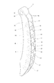
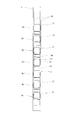
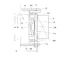
- FIG. 2 Schematic which shows the chain transmission of embodiment of this invention 1 is a perspective view of the chain guide shown in FIG. 2 is a longitudinal sectional view of the chain guide shown in FIG. Right side view of the chain guide shown in FIG. Sectional view along line VV in FIG.
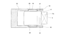
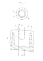
- FIG. 5 is an enlarged sectional view of the roller shown in FIG. Exploded front view showing part of guide base and rollers Enlarged sectional view of a roller according to another embodiment of the present invention Enlarged sectional view of a roller according to another embodiment of the present invention
- FIG. 1 shows a chain transmission device incorporating a chain guide according to an embodiment of the present invention.
- This chain transmission device spans between a drive sprocket 2 fixedly attached to a crankshaft 1 of an engine, a driven sprocket 4 fixedly attached to a camshaft 3, and the drive sprocket 2 and the driven sprocket 4.
- the rotation of the crankshaft 1 is transmitted to the camshaft 3 through the chain 5, and the combustion chamber valve (not shown) is opened and closed by the rotation of the camshaft 3.
- the rotation direction of the crankshaft 1 is constant (right rotation in the figure).
- the chain 5 is stretched on the side that is pulled into the drive sprocket 2 as the crankshaft 1 rotates.
- the portion on the side that is fed from the drive sprocket 2 is the slack side.
- a fixed chain guide 9 is provided on the tension side of the chain 5.
- the chain guide 7 extends vertically up and down along the chain 5, and a fulcrum shaft 6 is inserted into an insertion hole 10 provided at the upper end of the chain guide 7, and is supported so as to be swingable about the fulcrum shaft 6.
- a chain tensioner 8 is in contact with the swing end portion of the chain guide 7, and the chain guide 7 is pressed toward the chain 5 by the chain tensioner 8.
- the chain guide 9 also has a shape that extends vertically up and down along the chain 5, similarly to the chain guide 7.
- the chain guide 9 is fixed by tightening the bolts 14 by inserting bolts 14 into insertion holes 13 provided at both upper and lower ends.
- the swinging side chain guide 7 has an insertion hole 10 for inserting the swinging fulcrum shaft 6 at one end.
- the chain guide 9 on the fixed side is different from that formed in that the insertion holes 13 for inserting the fixing bolts 14 are formed at both ends, but otherwise the same configuration. It is.
- the chain guide 7 includes a guide base 15 extending in the traveling direction of the chain 5 and a plurality of rollers attached to the guide base 15 at intervals along the traveling direction of the chain 5.
- the shaft 16 includes a roller 17 rotatably supported on each roller shaft 16.
- the guide base 15 extends along the running direction of the chain 5 and is disposed between a pair of opposed side plates 18 and 18 that support both ends of each roller shaft 16 and the adjacent roller shafts 16, and the side plates 18 and 18. And a connecting portion 19 for connecting the two. Both ends of the connecting portion 19 are fixed to the side plate 18, and the facing interval of the side plate 18 is maintained. As shown in FIG. 3 and FIG. 7, the opposing surfaces of each side plate 18 communicate with the circular recess 20 that supports the shaft end of the roller shaft 16, and the circular recess 20 communicates from the convex edge of the side plate 18. A shaft introduction groove 21 is provided.
- the shaft introduction groove 21 is formed in a tapered shape in which the groove width gradually decreases from the convex edge of the side plate 18 toward the circular recess 20, and the shaft of the roller shaft 16 passes through the shaft introduction groove 21. The end is introduced into the circular recess 20.
- the width D 1 of the narrow portion of the shaft introducing groove 21 is larger than the inner diameter D 2 of the circular recessed portion 20. Is also formed to be small.
- the inner diameter D2 of the circular recess 20 is slightly smaller than the outer diameter d of the shaft end of the roller shaft 16, and the shaft end of the roller shaft 16 is fitted into the circular recess 20 with a margin.
- the guide base 15 can be formed by injection molding of a synthetic resin containing a fiber reinforcement.
- a synthetic resin for example, polyamide (PA) such as nylon 66 or nylon 46 can be used. Glass fiber, carbon fiber, aramid fiber, etc. can be used as the fiber reinforcing material to be blended in the synthetic resin.
- the guide base 15 may be formed of a light metal such as an aluminum alloy or a magnesium alloy.
- the roller shaft 16 is a solid cylindrical body formed of a steel material such as SUJ2 or SC material, and is heat-treated to improve the wear resistance of the surface. Examples of the heat treatment include bright quenching and induction quenching.
- the roller shaft 16 a solid structure instead of a hollow structure, it is possible to suppress a decrease in the cylindricity of the surface of the roller shaft 16 due to thermal distortion, and as a result, it is possible to suppress the rotation sound of the roller 17. Is possible.
- the roller 17 is rotatably mounted on the outer periphery of the roller shaft 16, and the cylindrical outer peripheral surface 17a of the roller 17 contacts the chain 5 for guidance.
- the roller 17 is a roller bearing including an outer ring 22, a plurality of rollers 23 incorporated inside the outer ring 22, and a cage 24 that holds these rollers 23.
- the outer ring 22 is a shell-shaped outer ring obtained by drawing a steel plate such as SPC or SCM into a cup shape, and is provided at a straight portion 22A having a constant outer diameter and at both ends of the straight portion 22A. It comprises a round portion 22B having a circular arc shape and a flange portion 22C extending radially inward from the round portion 22B.
- the rounded portion 22B having an arc-shaped cross section is provided at the end of the outer ring 22, the aggression against the guide base 15 when the end of the outer ring 22 contacts the guide base 15 is reduced, and wear of the guide base 15 is prevented. Can do.
- the outer ring 22 is a heat-treated product cured by heat treatment, and the wear resistance of the outer peripheral surface 17a is secured by the heat treatment.
- Examples of the heat treatment of the outer ring 22 include induction hardening, carburizing treatment, and carbonitriding treatment.
- the cylindricity of the outer peripheral surface 17a of the outer ring 22 is 20 ⁇ m or less in the state after the heat treatment.
- the cylindricity of the outer peripheral surface 17a is assumed to be a coaxial cylinder in which all points on the outer peripheral surface 17a are between two coaxial cylinders and the distance between the two cylinders in the radial direction is minimized. In the radial direction of the two cylinders.
- the thickness of a shell-type outer ring having an outer diameter of 25 mm or less is set to about 0.5 mm to 0.8 mm in order to facilitate drawing, but here, the thickness of the outer ring 22 is set to 1.
- the range is set to 0 mm to 3.0 mm. If the thickness of the outer ring 22 is 1.0 mm or more, the rigidity of the outer ring 22 is increased. Therefore, when heat treatment is performed, the cylindricity of the outer peripheral surface 17a is less likely to decrease, and the cylindricity of the outer peripheral surface 17a is 20 ⁇ m or less.
- a shell-shaped outer ring can be obtained.
- the thickness of the outer ring 22 is preferably 3.0 mm or less.
- the outer diameter of the straight portion 22A of the outer ring 22 is set in the range of 10 mm to 25 mm.
- the arc radius r of the outer surface of the round portion 22B is set in the range of 0.5 mm to 1.5 mm.
- the relationship between the width W of the outer ring 22 and the diameter H of the outer ring 22 is such that the running stability of the chain 5 can be improved by setting the width W of the outer ring 22 to 80% or more of the diameter H of the outer ring 22. .
- the outer ring 22 that contacts the chain 5 is made of steel, it has high strength. Moreover, the hardness of the steel outer ring 22 is higher than the hardness of the chain 5 and wear can be prevented.
- the outer ring 22 is made of a material that can be hardened by heat treatment, such as SUJ2 or SCM.
- the curing depth is preferably 0.05 mm or more.
- minute irregularities may be formed on the surface of the outer ring 22.
- the surface of the outer ring 22 may be nitrided to improve the strength.
- the generatrix shape of the surface of the outer ring 22 is preferably a drum shape or a straight shape in order to avoid local surface pressure due to point contact with the chain 5.
- the outer ring 22 can be formed by press molding or machining.
- the inward flange portions 22C at both ends are subjected to edge bending after the retainers 24 and 23 are assembled and heat-treated after assembly.
- the height between the outer ring 22 of the roller bearing constituting the roller 17 and the end surface of the guide base 15 is lower than the position of the connecting pin for connecting the plates constituting the chain 5. If the height between the outer ring 22 and the end face of the guide base 15 is higher than the position of the connecting pin that connects the plates constituting the chain 5, the connecting pin hits the opposing wall surface of the guide base 15, which is not preferable.
- FIG. 9 is a cross-sectional view showing another embodiment of the present invention.
- an oil hole 25 is provided at the center of the roller shaft 16, and a discharge hole 25 a through which oil is discharged is provided at a position opposite to the chain 5.
- the guide base 15 is provided with a hole 26 continuous with the oil hole 25.
- oil can be supplied into the bearing.
- heat can be released.
- the direction of the discharge hole 25a of the oil hole 25 is preferably opposite to that of the chain 5, so that the oil is smoothly supplied into the bearing.
- the roller shaft 16 is hollowed by the oil hole 25a, so that the weight can be reduced.
- the chain 5 travels between the drive sprocket 2 and the driven sprocket 4, and torque is transmitted from the crankshaft 1 to the camshaft 3 by the chain 5.
- the swing-side chain guide 7 keeps the tension of the chain 5 constant by pressing the chain 5 with the urging force of the chain tensioner 8, and the fixed-side chain guide 9 is used to run the ideal chain 5. The vibration of the chain 5 is suppressed while keeping the line.
- each roller 17 of the chain guides 7 and 9 rotates while contacting the back edge of each frame constituting the chain 5, and the contact between the chain 5 and the chain guides 7 and 9 is a rolling contact.
- Running resistance is small and torque transmission loss is small.
- the rotation speed of the crankshaft of the engine is about 8000 rpm at the maximum, but even when the crankshaft rotates at 3000 rpm, the roller 17 rotates at a high speed of about 6000 rpm to 9000 rpm.
- the contact pressure between the chain 5 and the roller 17 fluctuates even if the outer peripheral surface 17a of the roller 17 has a slight dimensional error.
- the chain 5 vibrates due to the fluctuation of the contact pressure, and the running sound of the chain 5 becomes loud.
- the cylindrical guide of the outer peripheral surface 17a of the roller 17 is set to 20 ⁇ m or less in the chain guide of this embodiment, when the roller 17 is in contact with the chain 5 in a state of rotating at a high speed, The contact pressure between the chain 5 and the roller 17 is unlikely to fluctuate. Therefore, the chain 5 is difficult to vibrate, the running sound of the chain 5 can be effectively suppressed, and the silence is excellent.
- the roller bearing in order to reduce the weight of the roller 17 and to minimize the running resistance of the chain 5, the roller bearing is used alone as the roller 17 so that the outer peripheral surface of the outer ring 22 becomes the outer peripheral surface 17a of the roller 17.
- a resin cylindrical member may be fitted to the outside of the outer ring 22 of the roller bearing with a tightening margin so that the outer peripheral surface of the cylindrical member becomes the outer peripheral surface 17 a of the roller 17.
- the outer ring 22 it is possible to use a solid type outer ring formed by machining, and it is also possible to use another type of bearing instead of the roller bearing.
- the roller bearing refers to a cylindrical roller bearing and a needle roller bearing.
- a silent chain As the chain 5 for transmitting the rotation of the crankshaft 1 to the camshaft 3, a silent chain, a roller chain, a bush chain in which a roller is omitted from the roller chain, and the like can be used.
Abstract
本発明は、静粛性に優れたチェーンガイドを提供することを課題とする。チェーン5の走行方向に延びるガイドベース15と、そのガイドベース15にチェーン5の走行方向に沿って間隔をおいて取り付けられた複数のローラ軸16と、その各ローラ軸16に回転可能に支持されたローラ17とからなり、そのローラ17の円筒状の外周面17aでチェーン5を案内するチェーンガイドにおいて、ローラ17の外周面17aの円筒度を20μm以下とする。
Description
この発明は、トルク伝達用チェーンの走行を案内するチェーンガイドおよびそのチェーンガイドを用いたチェーン伝動装置に関する。
自動車エンジンは、クランク軸の回転をタイミングチェーン(以下、単に「チェーン」という)を介してカム軸に伝達し、そのカム軸の回転により燃焼室のバルブを開閉する。
このようなカム軸駆動用のチェーン伝動装置として、クランク軸に取り付けられた駆動スプロケットと、カム軸に取り付けられた従動スプロケットと、駆動スプロケットと従動スプロケットの間に掛け渡されたチェーンと、そのチェーンの弛み側に配置された揺動可能なチェーンガイドと、そのチェーンガイドをチェーンに向けて押圧するチェーンテンショナと、チェーンの張り側に配置された固定のチェーンガイドとを有するものが多く用いられる。
ここで、揺動側のチェーンガイドは、チェーンテンショナの付勢力でチェーンを押圧することによりチェーンの張力を一定に保ち、固定側のチェーンガイドは、理想的なチェーンの走行ラインを保ちながらチェーンの振動を抑制する。
かかるチェーン伝動装置で使用される揺動側のチェーンガイドや固定側のチェーンガイドとして、チェーン走行方向に沿って延びる案内面をチェーンに滑り接触させる形式のものが知られているが、この滑り形式のチェーンガイドは、チェーンに対する接触が滑り接触なので、チェーンの走行抵抗が大きく、トルクの伝達ロスが大きいという問題がある。
このような問題を解消するため、チェーンの走行方向に延びるガイドベースと、そのガイドベースにチェーンの走行方向に沿って間隔をおいて取り付けられた複数のローラ軸と、その各ローラ軸に回転可能に支持されたローラとからなり、そのローラの円筒状の外周面で前記チェーンを案内するチェーンガイドが提案されている(特許文献1~3)。
このチェーンガイドは、チェーンに対する接触が転がり接触なので、チェーンの走行抵抗が小さく、トルクの伝達ロスが小さいという特徴がある。
ところで、この発明の発明者らは、上記転がり形式のチェーンガイドの性能を評価するために、クランク軸に取り付けた駆動スプロケットとカム軸に取り付けた従動スプロケットの間にチェーンを掛け渡し、そのチェーンの走行を転がり形式のチェーンガイドで案内する試験機を製作し、その試験機のクランク軸を、0を超える値から限界回転数までの範囲で回転させる試験を行なった。
その結果、転がり形式のチェーンガイドを使用することによって、滑り形式のチェーンガイドを使用した場合よりも、チェーンの走行抵抗を20~50%程度低減できることを確認することができたが、その一方で、転がり形式のチェーンガイドを使用した場合の方が、滑り形式のチェーンガイドを使用した場合よりも、チェーンの走行音が大きくなりやすいことが分かった。
この発明が解決しようとする課題は、静粛性に優れたチェーンガイドを提供することである。
本願発明の発明者らは、転がり形式のチェーンガイドを使用した場合にチェーンの走行音が大きくなる原因を究明したところ、エンジンのカム軸駆動用のチェーンを案内するときにローラが高速で回転した状態でチェーンに接触するので、ローラの外周面にわずかな寸法誤差があるだけでもチェーンとローラの間の接触圧が変動し、この接触圧の変動によってチェーンが振動することが、チェーンの走行音の原因の一つになっていることを見出した。
そして、上記課題を解決するため、この発明では、チェーンの走行方向に延びるガイドベースと、そのガイドベースにチェーンの走行方向に沿って間隔をおいて取り付けられた複数のローラ軸と、その各ローラ軸に回転可能に支持されたローラとからなり、そのローラの円筒状の外周面で前記チェーンを案内するチェーンガイドにおいて、前記ローラの外周面の円筒度を20μm以下に設定したのである。
このようにすると、ローラが高速で回転した状態でチェーンに接触しているときに、チェーンとローラの間の接触圧が変動しにくいので、チェーンが振動しにくく、チェーンの走行音を効果的に抑えることができる。
外輪の内側に複数のころを組み込んだころ軸受を、単独で前記ローラとして使用することができ、このとき、ころ軸受の外輪の外周面が前記ローラの外周面となる。この外輪は、熱処理が施された熱処理品とすることにより外周面の耐摩耗性を確保することができるが、外輪に熱処理を施すと、熱歪みによって外輪の外周面の円筒度が低下してしまう。そこで、外輪の肉厚は1.0mm以上に設定すると好ましい。このようにすると、外輪の剛性が高くなるので、熱処理を施したときに円筒度が低下しにくくなり、外周面の円筒度が20μm以下の外輪を得ることが可能となる。
前記外輪としては、鋼板の絞り加工により形成されたシェル形外輪を使用すると、削り加工により形成したソリッド形外輪を使用するよりも低コストである。一般に、シェル形外輪の肉厚は、絞り加工の容易化を図るために0.5mm~0.8mm程度に設定されるが、本願発明では、シェル形外輪の肉厚を1.0mm~3.0mmの範囲に設定すると好ましい。肉厚を1.0mm以上とすると、シェル形外輪の剛性が高くなるので、熱処理を施したときの円筒度の低下が小さくなり、外周面の円筒度が20μm以下のシェル形外輪を得ることが可能となる。また、シェル形外輪の肉厚が3.0mmよりも大きいと、外輪を形成するための絞り加工を複数回に分けて段階的に行なう必要が生じ、絞り加工の設備費および金型費用が上昇するため、シェル形外輪の肉厚は3.0mm以下が好適である。
前記外輪は、外径が一定のストレート部と、そのストレート部の両端に設けられた断面円弧状のアール部と、そのアール部から径方向内向きに延びる鍔部とからなるものを使用することができる。このように、外輪の端部に断面円弧状のアール部を設けると、外輪の端部がガイドベースに接触した場合のガイドベースに対する攻撃性が低減され、ガイドベースの摩耗を防止することができる。
前記アール部の外面の円弧半径は、0.5mm~1.5mmの範囲に設定すると好ましい。円弧半径を0.5mm以上とすることにより、外輪の端部がガイドベースに接触した場合のガイドベースに対する攻撃性を効果的に低減することができる。また、円弧半径を1.5mm以下とすることにより、外輪の全長を抑えながらストレート部の長さを確保して、チェーンを安定して案内することが可能となる。
前記ローラ軸としては、熱処理された中実の円柱体を使用すると好ましい。このようにすると、ローラ軸が熱処理により硬化されているので、ローラ軸の耐摩耗性を確保することができる。また、ローラ軸が中実なので、熱歪みによるローラ軸の表面の円筒度の低下を抑えることができ、その結果、ローラの回転音を抑えることが可能となる。
また、この発明では、上記のチェーンガイドを用いたチェーン伝動装置として、駆動スプロケットと従動スプロケットの間に掛け渡されたチェーンと、そのチェーンの弛み側に設けられた揺動可能な上記のチェーンガイドと、そのチェーンガイドをチェーンに向けて押圧するチェーンテンショナとを有するチェーン伝動装置を提供する。
チェーンの張り側に固定のチェーンガイドを更に設ける場合、その固定のチェーンガイドにも上記チェーンガイドを使用することができる。
この発明のチェーンガイドは、ローラの外周面の円筒度が20μm以下なので、ローラが高速で回転した状態でチェーンに接触しているときに、チェーンとローラの間の接触圧が変動しにくい。そのため、チェーンが振動しにくく、チェーンの走行音を効果的に抑えることができ、静粛性に優れる。
図1に、この発明の実施形態のチェーンガイドを組み込んだチェーン伝動装置を示す。このチェーン伝動装置は、エンジンのクランク軸1に固定して取り付けられた駆動スプロケット2と、カム軸3に固定して取り付けられた従動スプロケット4と、駆動スプロケット2と従動スプロケット4の間に掛け渡されたチェーン5を有し、このチェーン5を介してクランク軸1の回転をカム軸3に伝達し、そのカム軸3の回転により燃焼室のバルブ(図示せず)を開閉する。
エンジンが作動しているときのクランク軸1の回転方向は一定(図では右回転)であり、このときチェーン5は、クランク軸1の回転に伴って駆動スプロケット2に引き込まれる側の部分が張り側となり、駆動スプロケット2から送り出される側の部分が弛み側となる。そして、チェーン5の弛み側には、支点軸6を中心として揺動可能に支持されたチェーンガイド7と、チェーンガイド7をチェーン5に向けて押圧するチェーンテンショナ8とが設けられている。一方、チェーン5の張り側には、固定のチェーンガイド9が設けられている。
チェーンガイド7は、チェーン5に沿って上下に長く延び、その上端部に設けた挿入孔10に支点軸6が挿入され、この支点軸6を中心に揺動可能に支持されている。チェーンガイド7の揺動端部にはチェーンテンショナ8が接触しており、このチェーンテンショナ8によってチェーンガイド7はチェーン5に向けて押圧されている。
チェーンガイド9も、チェーンガイド7と同様に、チェーン5に沿って上下に長く延びる形状である。チェーンガイド9は、上下両端部にそれぞれ設けられた挿入孔13にボルト14が挿入され、このボルト14の締め付けによって固定されている。
ここで、揺動側のチェーンガイド7と固定側のチェーンガイド9とを対比した場合、揺動側のチェーンガイド7は、一端部に揺動の支点軸6を挿入するための挿入孔10が形成されているのに対し、固定側のチェーンガイド9は、両端部に固定用のボルト14を挿入するための挿入孔13が形成されている点で相違するが、その他の点では同一の構成である。
そのため、揺動側のチェーンガイド7について以下に説明し、固定側のチェーンガイド9については、対応する部分に同一の符号を付して説明を省略する。
図2~図4に示すように、チェーンガイド7は、チェーン5の走行方向に延びるガイドベース15と、そのガイドベース15にチェーン5の走行方向に沿って間隔をおいて取り付けられた複数のローラ軸16と、その各ローラ軸16に回転可能に支持されたローラ17とからなる。
ガイドベース15は、チェーン5の走行方向に沿って長く延びて各ローラ軸16の両端を支持する対向一対の側板18,18と、隣り合うローラ軸16の間に配置されて側板18,18同士を連結する連結部19とを有する。連結部19は、その両端が側板18に固定され、側板18の対向間隔を保持している。図3および図7に示すように、各側板18の互いに対向する対向面には、ローラ軸16の軸端を支持する円形凹部20と、側板18の凸側の縁から円形凹部20に連通する軸導入溝21とが設けられている。
図7に示すように、軸導入溝21は、側板18の凸側の縁から円形凹部20に向かって次第に溝幅が狭くなるテーパ状に形成され、この軸導入溝21を通じてローラ軸16の軸端を円形凹部20に導入するようになっている。ここで、円形凹部20内に導入されたローラ軸16の軸端が軸導入溝21に逆戻りするのを防止するため、軸導入溝21は、狭小部分の幅D1が円形凹部20の内径D2よりも小さくなるよう形成されている。
円形凹部20の内径D2は、ローラ軸16の軸端の外径dよりもわずかに小径とされ、ローラ軸16の軸端が締め代をもって円形凹部20に嵌合するようになっている。
ガイドベース15は、繊維強化材を配合した合成樹脂の射出成形により形成することができる。合成樹脂としては、例えば、ナイロン66やナイロン46などのポリアミド(PA)を使用することができる。合成樹脂に配合する繊維強化材は、ガラス繊維、カーボン繊維、アラミド繊維などを使用することができる。ガイドベース15はアルミニウム合金やマグネシウム合金等の軽金属で形成してもよい。
ローラ軸16は、SUJ2やSC材等の鋼材で形成された中実の円柱体であり、表面の耐摩耗性を向上させるために熱処理が施されている。熱処理としては、光輝焼入れ、高周波焼入れが挙げられる。このように、ローラ軸16を中空構造ではなく中実構造とすることにより、熱歪みによるローラ軸16の表面の円筒度の低下を抑えることができ、その結果、ローラ17の回転音を抑えることが可能となっている。
図5、図6に示すように、ローラ17は、ローラ軸16の外周に回転可能に装着され、ローラ17の円筒状の外周面17aがチェーン5に接触して案内を行なう。ここで、ローラ17は、外輪22と、外輪22の内側に組み込まれた複数のころ23と、これらのころ23を保持する保持器24とからなるころ軸受である。
図6に示すように、外輪22は、SPCやSCM等の鋼板をカップ状に絞り加工したシェル形外輪であり、外径が一定のストレート部22Aと、そのストレート部22Aの両端に設けられた断面円弧状のアール部22Bと、そのアール部22Bから径方向内向きに延びる鍔部22Cとからなる。外輪22の端部に断面円弧状のアール部22Bを設けると、外輪22の端部がガイドベース15に接触した場合のガイドベース15に対する攻撃性が低減され、ガイドベース15の摩耗を防止することができる。
この外輪22は、熱処理を施すことにより硬化した熱処理品であり、熱処理によって外周面17aの耐摩耗性が確保されている。外輪22の熱処理としては、高周波焼入れ、浸炭処理、浸炭窒化処理が挙げられる。また、外輪22の外周面17aの円筒度は、熱処理後の状態で20μm以下となっている。
ここで、外周面17aの円筒度とは、外周面17a上のすべての点が2つの同軸円筒の間にあり、その2つの円筒の半径方向の間隔が最小となるような同軸円筒を想定した場合の、2つの円筒の半径方向の間隔である。
一般に、外径が25mm以下のシェル形外輪の肉厚は、絞り加工の容易化を図るために0.5mm~0.8mm程度に設定されるが、ここでは、外輪22の肉厚を1.0mm~3.0mmの範囲に設定している。外輪22の肉厚を1.0mm以上とすると、外輪22の剛性が高くなるので、熱処理を施したときに外周面17aの円筒度が低下しにくくなり、外周面17aの円筒度が20μm以下のシェル形外輪を得ることが可能となる。また、外輪22の肉厚が3.0mmよりも大きいと、外輪22を形成するための絞り加工を複数回に分けて段階的に行なう必要が生じ、絞り加工の設備費および金型費用が上昇するため、外輪22の肉厚は3.0mm以下が好適である。
外輪22のストレート部22Aの外径は10mm~25mmの範囲に設定されている。アール部22Bの外面の円弧半径rは0.5mm~1.5mmの範囲に設定されている。円弧半径rを0.5mm以上とすることにより、外輪22の端部がガイドベース15の側板18に接触した場合の側板18に対する攻撃性を効果的に低減することができる。また、円弧半径rを1.5mm以下とすることにより、外輪22の全長を抑えながらストレート部22Aの長さを確保して、チェーン5を安定して案内することが可能となる。
図8は、外輪22の肉厚t1と、鍔部22Cの肉厚t2とを対比した場合に、外輪22の肉厚t1よりも鍔部22Cの肉厚t2を薄く形成した実施形態を示している。この実施形態は、外輪22の肉厚よりも鍔部22cの肉厚を薄く形成することにより、端面rを小さくできるので、チェーン5と接触する外輪22の幅Wが広くなり、高速で走行するチェーン5がローラ17に対して安定的に接触して、チェーン5の走行安定性を高めることができる。
また、外輪22の幅Wと、外輪22の径Hとの関係は、外輪22の幅Wを外輪22の径Hの80%以上にすることにより、チェーン5の走行安定性を高めることができる。
また、鍔部22Cの肉厚t2を薄くすることにより、保持器24の幅ところ23の長さを広げることができるため、ころ軸受の負荷容量を向上させることができる。WがHに比べて80%以下になると、ころ長さが短くなり、チェーン5が軸受軸方向にずれた際に軸受が傾き走行が不安定となる。
チェーン5と接触する外輪22は、鋼製であるので、高強度である。また、鋼製の外輪22の硬度は、チェーン5の硬度よりも高い方が摩耗を防止することができる。
外輪22の材質としては、SUJ2、SCM等、熱処理により硬化処理が行えるものを使用している。
外輪22を熱処理によって硬化させる場合、硬化深さは0.05mm以上あることが好ましい。
外輪22の表面には、潤滑油の保持性能を向上させるために、微小な凹凸を形成してもよい。
また、外輪22の表面は、窒化処理を施して強度を向上させてもよい。
前記外輪22の表面の母線形状は、チェーン5との点接触による局部面圧を避けるために、太鼓状又はストレート形状が望ましい。
前記外輪22は、プレス成形あるいは削り出し成形によって形成することができる。
プレス成形によって外輪22を形成する場合には、両端の内向きの鍔部22Cは、保持器24ところ23を組み込んだ後に、縁曲げ加工を行い、組立後に熱処理することが好ましい。
次に、対向一対の側板18,18間に、ローラ軸16を嵌め入れた状態で、図7、図8に示すように、ローラ17を構成するころ軸受の外輪22が、ガイドベース15の端面よりも低い。これにより、チェーン5が、ローラ17を構成するころ軸受の外輪22に接触しながらガイドベース15の対向壁面間で案内されて、走行するチェーン5がガイドベース15の対向壁面から外れることを防止している。
また、前記ローラ17を構成するころ軸受の外輪22とガイドベース15の端面までの高さは、チェーン5を構成するプレートを連結する連結ピンの位置よりも低くすることが望ましい。外輪22とガイドベース15の端面までの高さが、チェーン5を構成するプレートを連結する連結ピンの位置よりも高い位置にあると、連結ピンがガイドベース15の対向壁面に当たるので、好ましくない。
次に、図9は、この発明の他の実施形態を示す横断面図である。この実施形態につき、上述した実施形態と共通する構成については同一の符号を付して説明を省略し、異なる構成について以下に説明する。この実施形態では、図9に示すように、ローラ軸16の中心部に油穴25を設け、チェーン5と反対側の位置に油が排出される排出穴25aを設ける。そして、ガイドベース15に油穴25と連なる穴26を設ける。このように、油穴25を設けることにより、軸受内部に油が供給できる。また、熱を逃がすこともできる。油穴25の排出穴25aの方向は、上記のように、チェーン5と反対方向にするのが好ましく、これにより、軸受け内部へ油の供給がスムーズに行われる。さらに、油穴25aによりローラ軸16が中空になることにより、軽量化も図れる。
次に、上記構成からなるチェーン伝動装置の動作例を説明する。
エンジンが作動しているとき、駆動スプロケット2と従動スプロケット4の間でチェーン5が走行し、そのチェーン5によってクランク軸1からカム軸3にトルクが伝達される。このとき、揺動側のチェーンガイド7は、チェーンテンショナ8の付勢力でチェーン5を押圧することによりチェーン5の張力を一定に保ち、固定側のチェーンガイド9は、理想的なチェーン5の走行ラインを保ちながらチェーン5の振動を抑制する。
ここで、チェーンガイド7,9の各ローラ17は、チェーン5を構成する各コマの背側の縁に接触しながら回転し、チェーン5とチェーンガイド7,9の接触が転がり接触なので、チェーン5の走行抵抗が小さく、トルクの伝達ロスが小さい。
一般に、エンジンのクランク軸の回転数は最大で8000rpm程度であるが、クランク軸が3000rpmで回転するときでも、ローラ17は6000rpm~9000rpm程度の高速で回転する。このように、ローラ17は高速で回転した状態でチェーン5に接触するので、ローラ17の外周面17aにわずかな寸法誤差があるだけでもチェーン5とローラ17の間の接触圧が変動し、この接触圧の変動によってチェーン5が振動し、チェーン5の走行音が大きくなる可能性がある。
これに対し、この実施形態のチェーンガイドは、ローラ17の外周面17aの円筒度が20μm以下に設定されているので、ローラ17が高速で回転した状態でチェーン5に接触しているときに、チェーン5とローラ17の間の接触圧が変動しにくい。そのため、チェーン5が振動しにくく、チェーン5の走行音を効果的に抑えることができ、静粛性に優れる。
上記実施形態では、ローラ17を軽量化してチェーン5の走行抵抗を最小限に抑えるために、ころ軸受を単独でローラ17として用い、外輪22の外周面がローラ17の外周面17aとなるようにしているが、ころ軸受の外輪22の外側に樹脂製の円筒部材を締め代をもって嵌め合わせ、その円筒部材の外周面がローラ17の外周面17aとなるようにしてもよい。また、外輪22として、削り加工により形成したソリッド形外輪を使用することも可能であり、ころ軸受にかえて他の形式の軸受を用いることも可能である。ここで、ころ軸受とは、円筒ころ軸受および針状ころ軸受をいう。
クランク軸1の回転をカム軸3に伝達するチェーン5としては、サイレントチェーンのほか、ローラチェーンや、ローラチェーンからローラを省いたブシュチェーン等を採用することができる。
2 駆動スプロケット
4 従動スプロケット
5 チェーン
7 チェーンガイド
8 チェーンテンショナ
9 チェーンガイド
15 ガイドベース
16 ローラ軸
17 ローラ
17a 外周面
22 外輪
22A ストレート部
22B アール部
22C 鍔部
23 ころ
25 油穴
25a 排出穴
26 穴
r 円弧半径
4 従動スプロケット
5 チェーン
7 チェーンガイド
8 チェーンテンショナ
9 チェーンガイド
15 ガイドベース
16 ローラ軸
17 ローラ
17a 外周面
22 外輪
22A ストレート部
22B アール部
22C 鍔部
23 ころ
25 油穴
25a 排出穴
26 穴
r 円弧半径
Claims (13)
- チェーン(5)の走行方向に延びるガイドベース(15)と、そのガイドベース(15)にチェーン(5)の走行方向に沿って間隔をおいて取り付けられた複数のローラ軸(16)と、その各ローラ軸(16)に回転可能に支持されたローラ(17)とからなり、そのローラ(17)の円筒状の外周面(17a)で前記チェーン(5)を案内するチェーンガイドにおいて、前記ローラ(17)の外周面(17a)の円筒度が20μm以下であることを特徴とするチェーンガイド。
- 前記ローラ(17)が、外輪(22)の内側に複数のころ(23)を組み込んだころ軸受であり、そのころ軸受の前記外輪(22)の外周面が前記ローラ(17)の外周面(17a)であり、前記外輪(22)が熱処理品であり、その外輪(22)の肉厚が1.0mm以上である請求項1に記載のチェーンガイド。
- 前記外輪(22)が、鋼板の絞り加工により形成されたシェル形外輪であり、その外輪(22)の肉厚が3.0mm以下である請求項2に記載のチェーンガイド。
- 前記外輪(22)が、外径が一定のストレート部(22A)と、そのストレート部(22A)の両端に設けられた断面円弧状のアール部(22B)と、そのアール部(22B)から径方向内向きに延びる鍔部(22C)とからなる請求項3に記載のチェーンガイド。
- 前記アール部(22B)の外面の円弧半径(r)を0.5mm~1.5mmの範囲に設定した請求項4に記載のチェーンガイド。
- 前記外輪(22)の肉厚t1よりも鍔部(22C)の肉厚t2を薄く形成したことを特徴とする4又は5に記載のチェーンガイド。
- 前記外輪(22)の幅Wが、外輪(22)の径Hの80%以上である請求項1~6のいずれかに記載のチェーンガイド。
- 前記外輪(22)の硬度が、チェーン(5)の硬度よりも高い請求項1~7のいずれかに記載のチェーンガイド。
- 前記外輪(22)の母線形状が、太鼓状又はストレート形状である請求項1~8のいずれかに記載のチェーンガイド。
- 前記外輪(22)の表面に、潤滑油の保持性能を向上させる微小な凹凸が形成されている請求項1~9のいずれかに記載のチェーンガイド。
- 前記ローラ軸(16)が、熱処理された中実の円柱体である請求項1~10のいずれかに記載のチェーンガイド。
- 駆動スプロケット(2)と従動スプロケット(4)の間に掛け渡されたチェーン(5)と、そのチェーン(5)の弛み側に設けられた揺動可能なチェーンガイド(7)と、そのチェーンガイド(7)をチェーン(5)に向けて押圧するチェーンテンショナ(8)とを有するチェーン伝動装置において、前記チェーンガイド(7)が請求項1~11のいずれかに記載のチェーンガイドであることを特徴とするチェーン伝動装置。
- 前記チェーン(5)の張り側に設けられた固定のチェーンガイド(9)を更に有し、そのチェーンガイド(9)が請求項1~11のいずれかに記載のチェーンガイドである請求
項12に記載のチェーン伝動装置。
Priority Applications (3)
| Application Number | Priority Date | Filing Date | Title |
|---|---|---|---|
| CN201280029391.9A CN103620265A (zh) | 2011-06-13 | 2012-06-08 | 链条引导件和链条传动装置 |
| US14/125,459 US9562593B2 (en) | 2011-06-13 | 2012-06-08 | Chain guide and chain drive apparatus |
| EP12799729.4A EP2719922A4 (en) | 2011-06-13 | 2012-06-08 | CHAIN GUIDE AND CHAIN DRIVE APPARATUS |
Applications Claiming Priority (4)
| Application Number | Priority Date | Filing Date | Title |
|---|---|---|---|
| JP2011-131231 | 2011-06-13 | ||
| JP2011131231A JP5868617B2 (ja) | 2011-06-13 | 2011-06-13 | チェーンガイド及びチェーンテンショナ装置 |
| JP2011165424A JP5917847B2 (ja) | 2011-07-28 | 2011-07-28 | チェーンガイドおよびチェーン伝動装置 |
| JP2011-165424 | 2011-07-28 |
Publications (1)
| Publication Number | Publication Date |
|---|---|
| WO2012173056A1 true WO2012173056A1 (ja) | 2012-12-20 |
Family
ID=47357045
Family Applications (1)
| Application Number | Title | Priority Date | Filing Date |
|---|---|---|---|
| PCT/JP2012/064789 WO2012173056A1 (ja) | 2011-06-13 | 2012-06-08 | チェーンガイドおよびチェーン伝動装置 |
Country Status (4)
| Country | Link |
|---|---|
| US (1) | US9562593B2 (ja) |
| EP (1) | EP2719922A4 (ja) |
| CN (1) | CN103620265A (ja) |
| WO (1) | WO2012173056A1 (ja) |
Cited By (1)
| Publication number | Priority date | Publication date | Assignee | Title |
|---|---|---|---|---|
| CN105934606A (zh) * | 2014-02-17 | 2016-09-07 | Ntn株式会社 | 凸轮轴驱动用链传动装置 |
Families Citing this family (3)
| Publication number | Priority date | Publication date | Assignee | Title |
|---|---|---|---|---|
| JP6278673B2 (ja) * | 2013-11-28 | 2018-02-14 | Ntn株式会社 | チェーンガイドおよびチェーン伝動装置 |
| JP6265810B2 (ja) * | 2014-03-27 | 2018-01-24 | Ntn株式会社 | チェーンガイドおよびチェーン伝動装置 |
| CN109404419A (zh) * | 2018-10-25 | 2019-03-01 | 安徽省宁国顺昌机械有限公司 | 一种弧形导轨四点接触球轴承 |
Citations (5)
| Publication number | Priority date | Publication date | Assignee | Title |
|---|---|---|---|---|
| JPS62172847U (ja) * | 1986-04-23 | 1987-11-02 | ||
| JPH09236157A (ja) | 1996-02-29 | 1997-09-09 | Suzuki Motor Corp | エンジンのチェーンテンショナー装置 |
| JPH1144349A (ja) * | 1997-07-28 | 1999-02-16 | Tsubakimoto Chain Co | 伝動チェーンの走行案内シュー |
| WO2010090139A1 (ja) | 2009-02-03 | 2010-08-12 | Ntn株式会社 | チェーンガイドおよびチェーンテンショナ装置 |
| JP2010180900A (ja) | 2009-02-03 | 2010-08-19 | Ntn Corp | チェーンガイドおよびチェーンテンショナ装置 |
Family Cites Families (74)
| Publication number | Priority date | Publication date | Assignee | Title |
|---|---|---|---|---|
| US68625A (en) * | 1867-09-10 | Improvement in belt-tightener | ||
| US993684A (en) * | 1909-11-11 | 1911-05-30 | Felten & Guilleaume Lahmeyerwe | Transporting mechanism. |
| US1338293A (en) * | 1918-03-23 | 1920-04-27 | Renault Louis | Driving-chain |
| US1579245A (en) * | 1919-11-13 | 1926-04-06 | Gordon R Pennington | Spring suspension for track-laying tractors |
| USRE15894E (en) * | 1921-03-30 | 1924-08-19 | Basfb j | |
| US1499920A (en) * | 1923-01-17 | 1924-07-01 | Norfolk Iron Company | Conveyer |
| US2349281A (en) * | 1942-02-07 | 1944-05-23 | George H Kendall | Pulley bearing |
| US2341273A (en) * | 1942-08-05 | 1944-02-08 | Boeing Aircraft Co | Cable tensioning device |
| US2709371A (en) * | 1951-10-01 | 1955-05-31 | Singer Mfg Co | Universal bobbin winder pulleys |
| US2729110A (en) * | 1953-05-07 | 1956-01-03 | Automatic Steel Products Inc | Sheet metal pulley construction for tooth grip belts |
| US2892206A (en) * | 1953-11-12 | 1959-06-30 | Trico Products Corp | Windshield wiper drive mechanism |
| US2827153A (en) * | 1954-04-07 | 1958-03-18 | Rapids Standard Co Inc | Powered roll conveyors |
| US2964155A (en) * | 1958-12-26 | 1960-12-13 | Leonard B Flowers | Conveyor |
| US3598194A (en) * | 1968-06-10 | 1971-08-10 | Joachim Wappler | Final drive for terrain vehicle |
| US3586142A (en) * | 1969-05-01 | 1971-06-22 | Rapistan Inc | Rail for racks and the like |
| US3950046A (en) * | 1973-08-30 | 1976-04-13 | Industriewerk Schaeffler Ohg | Bearing plate |
| US3888217A (en) * | 1973-09-24 | 1975-06-10 | Charles A Hisserich | Camshaft belt drive for variable valve timing |
| US4078641A (en) * | 1974-04-04 | 1978-03-14 | F.E.I., Inc. | Sanitary roller conveyor |
| US3930323A (en) * | 1974-11-29 | 1976-01-06 | General Motors Corporation | Chain tensioning mechanism for scraper elevator device |
| US3951484A (en) * | 1975-04-14 | 1976-04-20 | Albert G. Nicholson | Roller assembly in a turn chain assembly |
| US4068535A (en) * | 1975-11-10 | 1978-01-17 | David L. Ray | Method and apparatus for controlling the tension of drive belts |
| US4208078A (en) * | 1977-08-29 | 1980-06-17 | Koyo Seiko Company Limited | Cylindrical roller bearings |
| US4213523A (en) * | 1978-09-11 | 1980-07-22 | C. L. Frost & Son, Inc. | Conveyor roller assembly |
| DE8025902U1 (de) * | 1980-09-27 | 1981-01-15 | Skf Kugellagerfabriken Gmbh, 8720 Schweinfurt | Rolle, insbesondere Spannrolle für Riementriebe o.dgl |
| US4474562A (en) * | 1980-12-03 | 1984-10-02 | Fag Kugelfischer Georg Schafer & Co. | Tensioner for motor-vehicle timing belt |
| US4416648A (en) * | 1981-01-12 | 1983-11-22 | Dyneer Corporation | Belt tensioner |
| US4416647A (en) * | 1981-05-26 | 1983-11-22 | Dayco Corporation | Belt tensioner |
| AU554589B2 (en) * | 1983-05-23 | 1986-08-28 | Fuji Kiko Co. Ltd. | Grooved pulley and manufacturing method therefor |
| JPH0247800Y2 (ja) * | 1985-04-30 | 1990-12-14 | ||
| US4723516A (en) * | 1985-11-25 | 1988-02-09 | Slagley Michael W | Valve open duration and timing controller |
| JPS62172847A (ja) | 1986-01-27 | 1987-07-29 | Matsushita Electric Works Ltd | 電話装置 |
| CS265980B1 (en) * | 1987-09-02 | 1989-11-14 | Burysek Frantisek | Device for belt pressure with spindleless spinning frame |
| JPH01150070A (ja) * | 1987-12-04 | 1989-06-13 | Mitsubishi Electric Corp | プーリおよびその製造方法 |
| US4969548A (en) * | 1988-04-27 | 1990-11-13 | Kornylak Corporation | Compression set limiting gravity conveyor |
| FR2640714B1 (fr) * | 1988-12-16 | 1991-02-08 | Caoutchouc Manuf Plastique | Dispositif de tension par transmission par lien souple a double galet sur bague elastique de torsion |
| US4892508A (en) * | 1989-06-13 | 1990-01-09 | Robert Ryan | Safety guide support for pivoting pulley |
| US5244439A (en) * | 1992-05-27 | 1993-09-14 | Rogus Thomas E | Roller chain idler replacement |
| US5368403A (en) * | 1993-04-30 | 1994-11-29 | Hewlett-Packard Company | Carriage support system for computer driven printer |
| US5441458A (en) * | 1994-01-14 | 1995-08-15 | Rogus; Thomas E. | Grooved roller chain idler |
| US5848846A (en) * | 1996-07-26 | 1998-12-15 | Ntn Corporation | Shell type needle roller bearing and method of producing the same |
| JP3805449B2 (ja) * | 1996-12-19 | 2006-08-02 | 株式会社椿本チエイン | ローラチェーン用走行案内シュー |
| JP3487540B2 (ja) * | 1997-07-01 | 2004-01-19 | 本田技研工業株式会社 | チェーン駆動車両のチェーンローラ構造 |
| JP3855383B2 (ja) * | 1997-08-07 | 2006-12-06 | 株式会社デンソー | プーリ一体型ロータの製造方法 |
| EP0931737A1 (en) * | 1998-01-22 | 1999-07-28 | Rexnord Marbett S.p.A. | A structure with idle rollers for guide walls of goods conveyors |
| US5967925A (en) * | 1998-03-30 | 1999-10-19 | Ford Global Technologies, Inc. | Pulley with controlled surface irregularity for an internal combustion engine |
| US6371653B2 (en) | 1998-10-07 | 2002-04-16 | Minebea Co., Ltd. | Anti-friction bearing and a motor including such a bearing |
| JP2000130527A (ja) * | 1998-10-30 | 2000-05-12 | Nissan Motor Co Ltd | Vベルト式無段変速機用プーリー及び無段変速機 |
| US6346057B1 (en) * | 1998-11-25 | 2002-02-12 | Klaus Edelmann | Belt tensioning device |
| US6245436B1 (en) * | 1999-02-08 | 2001-06-12 | David Boyle | Surfacing of aluminum bodies by anodic spark deposition |
| JP2000266064A (ja) * | 1999-03-18 | 2000-09-26 | Komatsu Ltd | 円筒ころ軸受及び針状ころ軸受用軸部品 |
| US6155218A (en) * | 1999-03-22 | 2000-12-05 | The United States Of America As Represented By The Secretary Of The Army | Cam advancing and retarding mechanism |
| US6179740B1 (en) * | 1999-06-02 | 2001-01-30 | Moxee Innovations Corporation | Dual-adjustable belt idler |
| US20010053727A1 (en) * | 2000-06-13 | 2001-12-20 | Eijiro Nakashima | Belt transmission system |
| ATE316625T1 (de) * | 2000-10-03 | 2006-02-15 | Gates Corp | Zweifacher, linearer riemenspannarm |
| DE10131916A1 (de) * | 2001-07-05 | 2003-01-23 | Muhr & Bender Kg | Spanneinrichtung für Zugmittel, insbesondere Riemenspanneinrichtung |
| EP1443228B1 (en) * | 2001-11-08 | 2011-03-30 | JTEKT Corporation | Bearing device for supporting pinion shaft |
| JP3336337B1 (ja) * | 2001-11-14 | 2002-10-21 | 株式会社椿本チエイン | 伝動装置用プラスチック製可動ガイド |
| US6866602B2 (en) * | 2002-07-01 | 2005-03-15 | Performance Engineering & Machine Inc. | Belt drive system |
| JP4123883B2 (ja) | 2002-09-19 | 2008-07-23 | 株式会社ジェイテクト | ころ軸受の製造方法 |
| JP4376503B2 (ja) * | 2002-10-25 | 2009-12-02 | ボルグワーナー・モールステック・ジャパン株式会社 | サイレントチェーン用スプロケットおよびその製造方法 |
| JP2005042879A (ja) * | 2003-07-25 | 2005-02-17 | Ntn Corp | 鋼板製軌道輪付きころ軸受 |
| CN1878965A (zh) * | 2003-09-12 | 2006-12-13 | 美蓓亚株式会社 | 流体动力轴承单元 |
| US7611289B2 (en) * | 2004-09-24 | 2009-11-03 | Ntn Corporation | Rollers with retainer |
| JP4851105B2 (ja) * | 2005-03-07 | 2012-01-11 | バンドー化学株式会社 | ベルト伝動装置 |
| WO2006138588A2 (en) * | 2005-06-16 | 2006-12-28 | Moxee Innovations Corporation | Tensioning device |
| DE102006002224A1 (de) * | 2006-01-16 | 2007-07-19 | Schaeffler Kg | Anordnung zum Schutz eines Substrates vor Korrosion, Verfahren zu dessen Herstellung sowie Riemenscheibe |
| US7815533B2 (en) * | 2006-09-18 | 2010-10-19 | Ford Global Technologies | Camshaft drive system for internal combustion engine |
| FR2907526B1 (fr) * | 2006-10-20 | 2009-06-26 | Skf Ab | Dispositif de galet tendeur ou enrouleur. |
| US7866292B2 (en) * | 2008-03-26 | 2011-01-11 | AES Industries Inc | Apparatus and methods for continuous variable valve timing |
| DE102009004562B4 (de) * | 2009-01-14 | 2015-06-03 | Shw Casting Technologies Gmbh | Walzenkörper für eine Walze zur Behandlung eines Materials und Verfahren zur Herstellung eines Walzenkörpers |
| JP5702528B2 (ja) | 2009-09-09 | 2015-04-15 | Ntn株式会社 | チェーンガイドおよびチェーンテンショナ装置 |
| JP2011089553A (ja) * | 2009-10-21 | 2011-05-06 | Ntn Corp | チェーンガイドおよびチェーンテンショナ装置 |
| EP2679863A4 (en) * | 2011-02-23 | 2015-08-05 | Ntn Toyo Bearing Co Ltd | CHAIN GUIDE AND CHAIN TENSIONER DEVICE |
| JP2012172810A (ja) * | 2011-02-23 | 2012-09-10 | Ntn Corp | チェーンガイド及びチェーンテンショナ装置 |
-
2012
- 2012-06-08 US US14/125,459 patent/US9562593B2/en not_active Expired - Fee Related
- 2012-06-08 EP EP12799729.4A patent/EP2719922A4/en not_active Withdrawn
- 2012-06-08 WO PCT/JP2012/064789 patent/WO2012173056A1/ja active Application Filing
- 2012-06-08 CN CN201280029391.9A patent/CN103620265A/zh active Pending
Patent Citations (5)
| Publication number | Priority date | Publication date | Assignee | Title |
|---|---|---|---|---|
| JPS62172847U (ja) * | 1986-04-23 | 1987-11-02 | ||
| JPH09236157A (ja) | 1996-02-29 | 1997-09-09 | Suzuki Motor Corp | エンジンのチェーンテンショナー装置 |
| JPH1144349A (ja) * | 1997-07-28 | 1999-02-16 | Tsubakimoto Chain Co | 伝動チェーンの走行案内シュー |
| WO2010090139A1 (ja) | 2009-02-03 | 2010-08-12 | Ntn株式会社 | チェーンガイドおよびチェーンテンショナ装置 |
| JP2010180900A (ja) | 2009-02-03 | 2010-08-19 | Ntn Corp | チェーンガイドおよびチェーンテンショナ装置 |
Non-Patent Citations (1)
| Title |
|---|
| See also references of EP2719922A4 |
Cited By (1)
| Publication number | Priority date | Publication date | Assignee | Title |
|---|---|---|---|---|
| CN105934606A (zh) * | 2014-02-17 | 2016-09-07 | Ntn株式会社 | 凸轮轴驱动用链传动装置 |
Also Published As
| Publication number | Publication date |
|---|---|
| US20140274512A1 (en) | 2014-09-18 |
| US9562593B2 (en) | 2017-02-07 |
| EP2719922A4 (en) | 2015-04-08 |
| CN103620265A (zh) | 2014-03-05 |
| EP2719922A1 (en) | 2014-04-16 |
Similar Documents
| Publication | Publication Date | Title |
|---|---|---|
| WO2012114959A1 (ja) | チェーンガイド及びチェーンテンショナ装置 | |
| WO2012114846A1 (ja) | チェーンガイド及びチェーンテンショナ装置 | |
| WO2012173056A1 (ja) | チェーンガイドおよびチェーン伝動装置 | |
| JP5706266B2 (ja) | チェーンガイドおよびチェーン伝動装置 | |
| CN103748383B (zh) | 凸轮轴驱动用的链传动装置 | |
| JP5897345B2 (ja) | タイミングチェーン駆動装置 | |
| WO2013047138A1 (ja) | チェーンガイドおよびチェーン伝動装置 | |
| JP5917847B2 (ja) | チェーンガイドおよびチェーン伝動装置 | |
| US9593750B2 (en) | Chain guide and chain transmission device | |
| JP5893884B2 (ja) | チェーンガイドおよびチェーン伝動装置 | |
| WO2017047491A1 (ja) | チェーンガイド及びチェーンテンショナ装置 | |
| WO2013011916A1 (ja) | チェーンガイドおよびチェーン伝動装置 | |
| JP5676305B2 (ja) | チェーンガイド及びチェーンテンショナ装置 | |
| JP2012189200A (ja) | チェーンガイド及びチェーンテンショナ装置 | |
| JP2012172808A (ja) | チェーンガイド及びチェーンテンショナ装置 | |
| JP5868617B2 (ja) | チェーンガイド及びチェーンテンショナ装置 | |
| JP5706260B2 (ja) | チェーンガイドおよびチェーン伝動装置 | |
| JP5662198B2 (ja) | チェーンガイド及びチェーンテンショナ装置 | |
| JP2012177390A (ja) | チェーンテンショナ装置 | |
| JP2013024297A (ja) | チェーンガイドおよびチェーン伝動装置 | |
| WO2012114845A1 (ja) | チェーンガイド及びチェーンテンショナ装置 | |
| JP5706259B2 (ja) | チェーンガイドおよびチェーン伝動装置 | |
| JP2012177391A (ja) | チェーンガイド及びチェーンテンショナ装置 | |
| JP2018040418A (ja) | チェーンガイドおよびチェーン伝動装置 | |
| JP2012189201A (ja) | チェーンガイド及びチェーンテンショナ装置 |
Legal Events
| Date | Code | Title | Description |
|---|---|---|---|
| 121 | Ep: the epo has been informed by wipo that ep was designated in this application |
Ref document number: 12799729 Country of ref document: EP Kind code of ref document: A1 |
|
| WWE | Wipo information: entry into national phase |
Ref document number: 14125459 Country of ref document: US |
|
| NENP | Non-entry into the national phase |
Ref country code: DE |