WO2012114846A1 - チェーンガイド及びチェーンテンショナ装置 - Google Patents
チェーンガイド及びチェーンテンショナ装置 Download PDFInfo
- Publication number
- WO2012114846A1 WO2012114846A1 PCT/JP2012/052452 JP2012052452W WO2012114846A1 WO 2012114846 A1 WO2012114846 A1 WO 2012114846A1 JP 2012052452 W JP2012052452 W JP 2012052452W WO 2012114846 A1 WO2012114846 A1 WO 2012114846A1
- Authority
- WO
- WIPO (PCT)
- Prior art keywords
- chain
- outer ring
- chain guide
- guide according
- iron
- Prior art date
Links
Images


Classifications
-
- F—MECHANICAL ENGINEERING; LIGHTING; HEATING; WEAPONS; BLASTING
- F16—ENGINEERING ELEMENTS AND UNITS; GENERAL MEASURES FOR PRODUCING AND MAINTAINING EFFECTIVE FUNCTIONING OF MACHINES OR INSTALLATIONS; THERMAL INSULATION IN GENERAL
- F16H—GEARING
- F16H7/00—Gearings for conveying rotary motion by endless flexible members
- F16H7/08—Means for varying tension of belts, ropes, or chains
- F16H7/10—Means for varying tension of belts, ropes, or chains by adjusting the axis of a pulley
- F16H7/12—Means for varying tension of belts, ropes, or chains by adjusting the axis of a pulley of an idle pulley
-
- F—MECHANICAL ENGINEERING; LIGHTING; HEATING; WEAPONS; BLASTING
- F16—ENGINEERING ELEMENTS AND UNITS; GENERAL MEASURES FOR PRODUCING AND MAINTAINING EFFECTIVE FUNCTIONING OF MACHINES OR INSTALLATIONS; THERMAL INSULATION IN GENERAL
- F16H—GEARING
- F16H7/00—Gearings for conveying rotary motion by endless flexible members
- F16H7/18—Means for guiding or supporting belts, ropes, or chains
-
- F—MECHANICAL ENGINEERING; LIGHTING; HEATING; WEAPONS; BLASTING
- F16—ENGINEERING ELEMENTS AND UNITS; GENERAL MEASURES FOR PRODUCING AND MAINTAINING EFFECTIVE FUNCTIONING OF MACHINES OR INSTALLATIONS; THERMAL INSULATION IN GENERAL
- F16H—GEARING
- F16H7/00—Gearings for conveying rotary motion by endless flexible members
- F16H7/08—Means for varying tension of belts, ropes, or chains
- F16H2007/0802—Actuators for final output members
- F16H2007/0806—Compression coil springs
-
- F—MECHANICAL ENGINEERING; LIGHTING; HEATING; WEAPONS; BLASTING
- F16—ENGINEERING ELEMENTS AND UNITS; GENERAL MEASURES FOR PRODUCING AND MAINTAINING EFFECTIVE FUNCTIONING OF MACHINES OR INSTALLATIONS; THERMAL INSULATION IN GENERAL
- F16H—GEARING
- F16H7/00—Gearings for conveying rotary motion by endless flexible members
- F16H7/08—Means for varying tension of belts, ropes, or chains
- F16H2007/0863—Finally actuated members, e.g. constructional details thereof
- F16H2007/0865—Pulleys
-
- F—MECHANICAL ENGINEERING; LIGHTING; HEATING; WEAPONS; BLASTING
- F16—ENGINEERING ELEMENTS AND UNITS; GENERAL MEASURES FOR PRODUCING AND MAINTAINING EFFECTIVE FUNCTIONING OF MACHINES OR INSTALLATIONS; THERMAL INSULATION IN GENERAL
- F16H—GEARING
- F16H7/00—Gearings for conveying rotary motion by endless flexible members
- F16H7/08—Means for varying tension of belts, ropes, or chains
- F16H2007/0863—Finally actuated members, e.g. constructional details thereof
- F16H2007/0872—Sliding members
-
- F—MECHANICAL ENGINEERING; LIGHTING; HEATING; WEAPONS; BLASTING
- F16—ENGINEERING ELEMENTS AND UNITS; GENERAL MEASURES FOR PRODUCING AND MAINTAINING EFFECTIVE FUNCTIONING OF MACHINES OR INSTALLATIONS; THERMAL INSULATION IN GENERAL
- F16H—GEARING
- F16H7/00—Gearings for conveying rotary motion by endless flexible members
- F16H7/08—Means for varying tension of belts, ropes, or chains
- F16H2007/0889—Path of movement of the finally actuated member
- F16H2007/0891—Linear path
Definitions
- the present invention relates to a chain guide and a chain tensioner device for applying tension so that a chain stretched endlessly is pressed to prevent the chain from slackening.
- a chain guide that contacts the chain is installed in the middle of the chain spanned endlessly between the drive sprocket and the driven sprocket, and at least one of the chain guides is set substantially perpendicular to the traveling direction of the chain.
- the present invention seeks to obtain a chain guide having a large inertial force and less vibration and a chain tensioner device using the same without increasing the weight of the entire system. It is.
- the present invention is designed to increase the inertia force of the chain guide and increase the vibration of the chain guide without increasing the weight of the entire system by integrally attaching the tensioner plunger to the chain guide base. This is intended to reduce this.
- the chain guide base can be provided with a plurality of rollers that come into contact with the endlessly spanned chain.
- the roller can be constituted by a support shaft supported at both ends by a chain guide base and a roller bearing having an outer ring provided on the outer peripheral surface of the support shaft. Moreover, you may have the iron outer ring which covered the outer periphery of this outer ring and contacts a chain.
- the roller bearing may be composed of a steel outer ring having inward flanges at both ends and a roller with a cage incorporated in the outer ring.
- the steel outer ring is formed by press molding, but may be formed by cut-out molding.
- the hardness of the iron outer ring is preferably higher than the hardness of the chain so that it does not easily wear even when the chain running at high speed comes into contact.
- the material of the iron outer ring for example, a material that can be cured, such as SUJ2 and SCM, is preferable.
- the thickness of the iron outer ring is preferably 1 mm or more in order to prevent deformation and improve strength.
- the bus shape of the iron outer ring is preferably a drum shape or a straight shape in order to reduce sliding resistance with the chain.
- the surface of the iron outer ring may be subjected to nitriding treatment as a hardening treatment.
- the roundness of the iron outer ring is preferably 20 ⁇ m or less in order to reduce vibration and achieve quietness.
- a chain tensioner device in which a chain guide according to the present invention is arranged in the middle of an endlessly stretched chain and a tensioner plunger attached integrally to the chain guide base is used to apply tension to the chain. Can do.
- the tensioner plunger is integrally attached to the chain guide base, so that the weight of the chain guide increases by the weight of the tensioner plunger, so that a large inertial force is obtained by the weight increase, Vibration is reduced. Even if the weight of the entire chain guide increases, the weight of the vehicle as a whole does not change from the case where the tensioner plunger is arranged on the engine side, so the fuel efficiency is not deteriorated.
- FIG. 5 is a cross-sectional view taken along line AA in FIG. 4. It is the elements on larger scale of FIG.
- It is a transverse cross section showing one embodiment of a chain guide concerning this invention. It is a transverse cross section showing one embodiment of a chain guide concerning this invention. It is a cross-sectional view showing another embodiment of the chain guide according to the present invention. It is a front view which shows an example of the chain tensioner apparatus which uses the chain guide which concerns on this invention.
- the chain guide according to the embodiment of the present invention is used, for example, to apply tension to a timing chain of an engine valve drive system.
- the timing chain 1 includes a crank sprocket 2 attached to the crankshaft, a first cam sprocket 3 attached to the first camshaft of the valve operating mechanism, and a second cam sprocket attached to the second camshaft. 4 is wound endlessly.
- the timing chain 1 between the crank sprocket 2 and the first cam sprocket 3 and between the crank sprocket 2 and the second cam sprocket 4 has a first chain guide 5a and a second chain so that the timing chain 1 does not loosen.
- a guide 5b is provided.
- the first chain guide 5a is configured such that one end side in the longitudinal direction is rotatably supported by the engine by the rotating shaft 6 and the other end side is swung by the tensioner plunger 7, and applies tension to the timing chain 1. ing.
- the second chain guide 5b is fixed so that both ends in the longitudinal direction are fixed to the engine by the mounting shaft 8 so that the tensioned timing chain 1 is not loosened.
- the first chain guide 5a and the second chain guide 5b are fixed to the engine without the second chain guide 5b oscillating while the first chain guide 5a is oscillated by the tensioner plunger 7.
- the basic structure for guiding the timing chain 1 is the same except for the difference.
- the chain guides 5a and 5b are also referred to as chain levers.
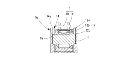
- the chain guide 5a has a tensioner plunger 7 integrally attached to a guide base 9 formed in a curved shape along the timing chain 1.
- the tensioner plunger 7 is inserted into the cylinder chamber 7a, the piston 7b slidably provided in the cylinder chamber 7a, and the piston 7b, and presses the piston 7b outward. Return spring 7c.
- the cylinder chamber 7a is provided with a pressure chamber 7d on the back side of the piston 7b, an oil supply passage 7e for supplying hydraulic oil to the pressure chamber 7d, and a check valve 7f for preventing backflow of the hydraulic oil.
- an annular fixed step portion 10 for fitting the cylinder chamber 7 a is provided on the bottom surface of the guide base 9, and the cylinder chamber 7 a is press-fitted into the fixed step portion 10.
- a bonding method, a screw connection method, or the like can be employed.
- the cylinder chamber 7a may be attached by insert molding.
- the chain guide base 9 includes a pair of side plate members 9a and a column member 9b connecting the side plate members 9a.
- Through holes 11 are provided at both ends in the longitudinal direction of the side plate member 9a.
- a shaft (not shown) is inserted into the through hole 11 and attached to the inner wall of the engine cover, for example.
- One end side in the longitudinal direction of the first chain guide 5a is rotatably supported by the engine by the rotating shaft 6, and the other end side is swung by the tensioner plunger 7 to adjust the tension of the timing chain 1. .
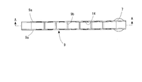
- the pair of side plate members 9a have a predetermined interval in the width direction, and a plurality of rollers 12 that contact the timing chain 1 are arranged between the side plate members 9a.
- the arrangement of the rollers 12 may be uniform with respect to the curved side plate member 9a, or may be different so that many rollers 12 are arranged on the entrance side of the timing chain 1 in the running direction. Good.
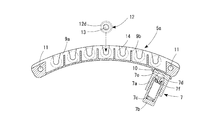
- Support recesses 14 that support both ends of the support shaft 13 of the roller 12 are provided on the opposing wall surface of the side plate member 9a.
- the support recess 14 includes an insertion recess 14 a that opens to the end surface on the timing chain 1 side, and an end of the support shaft 13 that is continuous with the insertion recess 14 a.
- the both ends of the support shaft 13 of the roller 12 are inserted into the fixed recess 14b from the insertion recess 14a, and the both ends of the side plate member 9 are inserted into the fixed recess 14b. I support it.
- a plurality of the support recesses 14 are arranged along the curved shape of the side plate member 9 a, and a column member 9 b is disposed between the support recess 14 and the support recess 14.
- the insertion recess 14a is formed in a tapered shape having a wide opening a and gradually narrowing to a position reaching the fixed recess 14b.
- the width dimension of the insertion port b at a position where it is connected to the location 14b is smaller than the diameter ⁇ of the arc-shaped fixed recess 14b.
- the diameter ⁇ of the arc-shaped fixed recess 14b is formed smaller than the diameter of the support shaft 13, and the support shaft 13 is press-fitted and fixed to the fixed recess 14b.
- the support recess 14 is formed in the side plate member 9 in a non-penetrating state. Thereby, the movement of the inserted support shaft 13 in the axial direction is restricted.
- the side plate member 9a and the column member 9b are integrally formed by resin molding using, for example, polyamide (PA) 46 or polyamide (PA) 66, which is a polymer obtained by polycondensation of diaminobutane and adipic acid. Is done. Moreover, in order to increase mechanical strength, the thing which compounded glass fiber and carbon fiber in PA46 and PA66 can also be used.
- PA polyamide
- PA polyamide
- the weight can be reduced by forming the side plate member 9a and the column member 9b with resin. Moreover, the resin which forms with the side plate member 9a and the column member 9b can also use a highly heat conductive thing in order to thermally radiate friction heat.
- the side plate member 9a and the column member 9b can be formed by casting using a light metal such as aluminum or magnesium other than the resin, and in that case, it is preferably integrated with the tensioner plan jack.
- the roller 12 may be constituted by a roller bearing having the support shaft 13 and a steel outer ring 12a as shown in FIG. 7, or as shown in FIG. 8, the outer peripheral surface of the steel outer ring 12a.
- an iron outer ring 12d that contacts the timing chain 1 may be covered.
- the roller bearing is a radial roller bearing including a steel outer ring 12a having inward flanges at both ends and a roller 12c with a cage 12b incorporated in the outer ring 12a.
- the outer ring 12a can be formed by press molding or machining.
- the inward flanges at both ends are subjected to edge bending after the cage 12b and 12c are assembled, and heat-treated after assembly.
- the hardness of the outer ring 12a or the iron outer ring 12d is higher than the hardness of the timing chain 1, so that wear can be prevented.
- a material that can be hardened by heat treatment such as SUJ2 or SCM, is used.
- fine irregularities may be formed on the surface of the outer ring 12a or the iron outer ring 12d.
- the surface of the outer ring 12a or the iron outer ring 12d may be subjected to nitriding treatment.
- the shape of the bus bar on the surface of the outer ring 12a or the iron outer ring 12d is preferably a drum shape or a straight shape.
- the roundness of the outer ring 12a or the iron outer ring 12d is preferably 20 ⁇ m or less in order to reduce vibration and achieve quietness.
- the thickness of the outer ring 12a or the iron outer ring 12d is preferably 1 mm or more in terms of strength.
- the rollers 12c are held at a predetermined interval in the circumferential direction by the cage 12b.
- a V-type cage having a V-shaped column part is used as the cage 12b.
- the skew of the roller 12c can be prevented, the end surface of the roller 12c can be prevented from directly touching the flange portion of the outer ring 12a, and wear of the side plate member 9 can be prevented.
- a roller 12 fitted with a support shaft 13 is prepared. Then, both ends of the support shaft 13 of the roller 12 face the insertion recess 14a of the support recess formed on the opposing wall surface of the side plate member 9a, and are fixed into the insertion recess 14a by dropping into the insertion recess 14a. Insert into the recess 14b.
- the opening a is wide and the insertion recess 14a is formed in a taper shape, when the support shaft 13 is inserted, the support shaft 13 can be easily moved from the opening a through the insertion port b. It can be guided to the arcuate fixed recess 14b.
- the support shaft 13 is press-fitted and attached to the fixed recess 14b. As a result, the rotation of the support shaft 13 can be suppressed. Moreover, since the width of the insertion port b connected to the fixed recess 14b is smaller than the diameter ⁇ of the arc-shaped fixed recess 14b, the insertion port b functions to prevent the support shaft 13 from coming off. Furthermore, since the support recess 14 is formed so as not to penetrate the side plate member 9, it is possible to restrict the axial movement of the support shaft 13 to be inserted.
- the roller 12 With the support shaft 13 of the roller 12 fitted in the support recess 14 of the opposing side plate member 9a, as shown in FIGS. 1, 3, 4, 7 and 8, the roller 12 The outer peripheral surface is lower than the end surface of the side plate member 9a. As a result, the timing chain 1 is guided between the opposing wall surfaces of the side plate member 9a while being in contact with the iron outer ring 12d, thereby preventing the traveling timing chain 1 from coming off the opposing wall surface of the side plate member 9a.
- the height to the end surface of the roller 12 and the side plate member 9a is lower than the position of the connecting pin 1b that connects the plates 1a constituting the timing chain 1. . If the height to the end face of the roller 12 and the side plate member 9 is higher than the position of the connecting pin 1b that connects the plate 1a constituting the timing chain 1, the connecting pin 1b hits the opposing wall surface of the side plate member 9. It is not preferable.
- FIG. 9 is a cross-sectional view showing a chain guide 5a according to another embodiment of the present invention.
- an oil hole 15 is provided at the center of the support shaft 13, and a discharge hole 15 a through which oil is discharged is provided at a position opposite to the timing chain 1.
- the side plate member 9 is provided with a hole 16 that is continuous with the oil hole 15.
- the direction of the discharge hole 15a of the oil hole 15 is preferably opposite to that of the timing chain 1, so that the oil is smoothly supplied into the bearing. Further, the support shaft 13 is hollowed by the oil hole 15a, so that the weight can be reduced.
- chain guide 5a of each embodiment of the present invention can apply tension to various drive chains in addition to the engine timing chain, and can reduce mechanical loss.
- the rotary shaft 6 is inserted into the through hole 11 at one end, and the other end is swung by the tensioner plunger 7.
- the chain guide 5a and the second chain guide 5b, both ends of which are fixed to the engine by the mounting shaft 8, are configured. According to this chain tensioner device, the mechanical loss of the engine timing chain can be reduced and the weight thereof can be reduced, and the fuel consumption rate can be improved.
- timing chain 1 can be either a roller chain or a silent chain.
- the hydraulic tensioner plunger is shown.
- a mechanical tensioner plunger using a screw or a spring may be integrally attached to the chain guide.
- the chain guide according to the present invention is effectively used in a mechanism that applies tension to a drive chain such as an engine.
Abstract
高速で走行するチェーンが接触しても、低騒音で、振動の少ないチェーンガイド並びにそれを用いたチェーンテンショナ装置を提供する。チェーン1の走行方向に沿って設けられるチェーンガイドベース9に、チェーンガイドベース9をチェーン側に押し付けるテンショナプランジャー7を一体に取付け、チェーンガイド5自体の重量を増加させることにより、振動を低減させる構成とした。
Description
この発明は、無端状に架け渡されたチェーンを押圧してチェーンに弛みが生じないように張力を付与するチェーンガイドおよびチェーンテンショナ装置に関するものである。
チェーンテンショナ装置は、駆動スプロケットと従動スプロケットに無端状に架け渡されたチェーンの途中部分に、チェーンに接触するチェーンガイドを設置し、チェーンガイドの少なくとも一つをチェーンの走行方向と略直角方向に押し付けることによって、高速で走行するチェーンに弛みが生じないように張力を付与するものであり、エンジンの動弁駆動装置のタイミングチェーン等に使用されている。
チェーンガイドは、チェーンと接触しながら案内するものであるから、チェーンとの間で摩擦による摺動抵抗が発生し、騒音やメカニカルロスが大きくなるという問題が生じる。
このチェーンガイドの騒音やメカニカルロスを抑制する技術として、特許文献1あるいは特許文献2に記載のものが知られている。これらの文献に記載のチェーンガイドは、チェーンの走行方向に沿って湾曲形状に形成され、チェーンと接触する摺動面部にローラを配設し、高速で走行するチェーンをローラが転がりながら押圧することによって、摺動抵抗を減少させるものである。
ところで、チェーンは、チェーンガイド上を振動しながら高速で移動するので、その振動がチェーンガイドを介してエンジンに伝わり、音響値が大きくなるという問題がある。
このチェーンガイドに伝わる振動を小さくする対策として、チェーンガイドを重くすることで、慣性力を大きくすることが考えられる。
ところが、チェーンガイド自体を重くすることは、システム全体として重量増になるため、燃費向上の観点から好ましくない。
そこで、この発明は、上記の課題を解決するために、慣性力が大きくて振動の少ないチェーンガイド並びにそれを用いたチェーンテンショナ装置を、システム全体としての重量を増加させることなく得ようとするものである。
前記の課題を解決するために、この発明は、テンショナプランジャーを、チェーンガイドベースに一体に取付けることにより、システム全体としての重量を増加させることなく、チェーンガイドの慣性力を大きくして、振動の低減を図ったものである。
前記チェーンガイドベースには、無端状に架け渡されたチェーンと接触する複数のローラを配設することができる。
前記ローラは、チェーンガイドベースに両端を支持された支持軸と、この支持軸の外周面に設けられた外輪を備えるころ軸受とによって構成することができる。また、この外輪の外周に被せられた、チェーンに接触する鉄製外環を有していてもよい。
前記ころ軸受は、両端に内向きの鍔部を有する鋼製の外輪と、この外輪内に組込まれる保持器付きのころとからなるものを使用することができる。
前記鋼製の外輪は、プレス成形によって形成されるが、削り出し成形によって形成してもよい。
前記鉄製外環の硬度は、高速で走行するチェーンが接触しても摩耗しにくいように、チェーンの硬度よりも高いものを使用することが好ましい。
前記鉄製外環の材質としては、例えば、SUJ2、SCM等の硬化処理が行えるものが好ましい。
前記鉄製外環の肉厚は、変形を防止、強度を向上させるために、1mm以上が好ましい。
前記鉄製外環の母線形状は、チェーンとの摺動抵抗を小さくするために、太鼓状又はストレート形状が望ましい。
前記鉄製外環の表面には、潤滑油の保持性能を向上させるために、微小な凹凸を形成することが好ましい。
また、前記鉄製外環の表面に硬化処理として、窒化処理を施してもよい。
前記鉄製外環の真円度は、振動を軽減し、静粛性を図るために、20μm以下が望ましい。
この発明に係るチェーンガイドを、無端状に架け渡されたチェーンの途中部分に配置し、チェーンガイドベースに一体に取り付けたテンショナプランジャーを使用してチェーンに張力を付与するチェーンテンショナ装置にすることができる。
この発明のチェーンガイドは、チェーンガイドベースにテンショナプランジャーを一体に取り付けているので、テンショナプランジャーの重量分だけチェーンガイドの重量が増加するので、その重量増加分だけ大きな慣性力が得られ、振動が低減する。
チェーンガイド全体の重量が増加しても、テンショナプランジャーをエンジン側に配置する場合と、車両全体としての重量は変わらないので、燃費性能を悪化させることはない。
チェーンガイド全体の重量が増加しても、テンショナプランジャーをエンジン側に配置する場合と、車両全体としての重量は変わらないので、燃費性能を悪化させることはない。
この発明の実施の形態について図面を参照しながら詳細に説明する。なお、図中同一または相当部分には同一符号を付し、説明の重複を避けるためにその説明は繰返さない。
この発明の実施形態にかかるチェーンガイドは、例えば、エンジンの動弁駆動系のタイミングチェーンに張力を付与するために使用される。
タイミングチェーン1は、図9に示すように、クランク軸に取付けられるクランクスプロケット2と、動弁機構の第1カムシャフトに取り付けられる第1カムスプロケット3及び第2カムシャフトに取り付けられる第2カムスプロケット4の間に無端状に巻き掛けられている。
クランクスプロケット2と第1カムスプロケット3間、及びクランクスプロケット2と第2カムスプロケット4の間のタイミングチェーン1には、それぞれタイミングチェーン1が緩まないように第1のチェーンガイド5aと第2のチェーンガイド5bを配設している。
第1のチェーンガイド5aは、長手方向の一端側が回転軸6によってエンジンに回転自在に支持され、他端側をテンショナプランジャー7によって揺動するように構成され、タイミングチェーン1に張力を付与している。
第2のチェーンガイド5bは、長手方向の両端が取付け軸8によってエンジンに対して固定され、張力が付与されたタイミングチェーン1が弛まないように案内している。
第1のチェーンガイド5aと第2のチェーンガイド5bは、第1のチェーンガイド5aがテンショナプランジャー7によって揺動するのに対し、第2のチェーンガイド5bが揺動しないでエンジンに対して固定される点で相違するのみで、タイミングチェーン1を案内する基本構造は同一である。なお、チェーンガイド5a、5bは、チェーンレバーとも称される。
チェーンガイド5aは、タイミングチェーン1に沿うように湾曲形状に形成されたガイドベース9に、テンショナプランジャー7を一体に取り付けている。
テンショナプランジャー7は、図5に示すように、シリンダ室7aと、このシリンダ室7a内に摺動自在に設けられたピストン7bと、このピストン7b内に挿入され、ピストン7bを外方向に押圧するリターンスプリング7cとを備えている。
シリンダ室7aには、ピストン7bの奥側に圧力室7dと、この圧力室7dに作動油を供給する給油通路7eと、作動油の逆流を防止するチェックバルブ7fとが設けられている。
チェーンガイドベース9とテンショナプランジャー7との固定方法としては、ガイドベース9の底面にシリンダ室7aを嵌める環状の固定段部10を設け、固定段部10内にシリンダ室7aを圧入する方法の他、接着する方法、あるいはネジ結合する方法等を採用することができる。
ガイドベース9を成形する際に、シリンダ室7aをインサート成型により取付けるようにしてもよい。
チェーンガイドベース9は、一対の側板部材9aと、側板部材9aをつなぐ柱部材9bとからなる。
前記側板部材9aの長手方向両端には、貫通孔11が設けられている。この貫通孔11に軸(図示しない)を挿入し、例えば、エンジンカバーの内壁に取り付けられる。
前記第1チェーンガイド5aの長手方向の一端側は、回転軸6によってエンジンに回転自在に支持し、他端側をテンショナプランジャー7によって揺動させて、タイミングチェーン1の張力を調整している。
前記一対の側板部材9aは、幅方向に所定の間隔を有し、側板部材9a間にタイミングチェーン1と接触する複数のローラ12が配列される。このローラ12の配列は、湾曲形状の側板部材9aに対して、均一なピッチでもよいし、タイミングチェーン1の走行方向の入口側にローラ12が多く配列されるように、ピッチを異ならせてもよい。
側板部材9aの対向壁面には、ローラ12の支持軸13の両端を支持する支持凹所14が設けられている。
支持凹所14は、図4、図5及び図6に示すように、前記タイミングチェーン1側の端面に開口する挿入凹所14aと、この挿入凹所14aに連続し、前記支持軸13の端部が嵌まる円弧形状の固定凹所14bとからなり、前記ローラ12の支持軸13の両端を、前記挿入凹所14aから前記固定凹所14b内に挿入して、前記側板部材9の両端を支持している。
前記支持凹所14は、図5に示すように、側板部材9aの湾曲形状に沿って複数配列され、支持凹所14と支持凹所14の間に柱部材9bが配置されている。
前記挿入凹所14aは、図6の拡大図に示すように、開口部aが広く、固定凹所14bに至る位置まで徐々に狭くなって行くテーパ状に形成され、挿入凹所14aと固定凹所14bとが連なる位置の挿入口bの幅寸法が、円弧形状の固定凹所14bの径φより小さく形成されている。
前記円弧形状の固定凹所14bの径φは、前記支持軸13の径より小さく形成され、前記支持軸13が固定凹所14bに圧入固定されるようになっている。
また、この支持凹所14は、図1及び図2に示すように、側板部材9に非貫通状態で形成されている。これにより、挿入された支持軸13の軸方向の移動が規制されている。
前記側板部材9a及び柱部材9bは、この実施形態では、例えば、ジアミノンブタンとアジピン酸の重縮合によるポリマーであるポリアミド(PA)46やポリアミド(PA)66を用いた樹脂成形により一体に成形される。また、機械的強度を増すために、ガラス繊維や炭素繊維をPA46、PA66に複合させたものを用いることもできる。
側板部材9aと柱部材9bを樹脂で形成することにより、軽量化が図れる。また、側板部材9aと柱部材9bと形成する樹脂は、摩擦熱を放熱するために、高熱伝導性のものを用いることもできる。
なお、側板部材9aと柱部材9bは、樹脂以外でも、例えば、アルミニウム、マグネシウムなどの軽金属を用いて鋳造によって形成することもでき、その場合にはテンショナプランジャックと一体化させることが好ましい。
前記ローラ12は、図7に示すように、前記支持軸13と、鋼製の外輪12aを有するころ軸受によって構成してもよいし、図8に示すように、鋼製の外輪12aの外周面に、タイミングチェーン1と接触する鉄製外環12dを被せるようにしてもよい。
前記ころ軸受は、両端に内向きの鍔部を有する鋼製の外輪12aと、この外輪12a内に組込まれる保持器12b付きのころ12cとからなるラジアルころ軸受である。
前記外輪12aは、プレス成形あるいは削り出し成形によって形成することができる。
プレス成形によって外輪12aを形成する場合には、両端の内向きの鍔部は、保持器12bところ12cを組み込んだ後に、縁曲げ加工を行い、組立後に熱処理することが好ましい。
また、外輪12a又は鉄製外環12dの硬度は、タイミングチェーン1の硬度よりも高い方が摩耗を防止することができる。
外輪12a又は鉄製外環12dの材質としては、SUJ2、SCM等、熱処理により硬化処理が行えるものを使用している。
外輪12a又は鉄製外環12dの表面には、潤滑油の保持性能を向上させるために、微小な凹凸を形成してもよい。
また、外輪12a又は鉄製外環12dの表面は、窒化処理を施してもよい。
前記外輪12a又は鉄製外環12dの表面の母線形状は、タイミングチェーン1との接触抵抗を低減させるために、太鼓状又はストレート形状が望ましい。
前記外輪12a又は鉄製外環12dの真円度は、振動を軽減し、静粛性を図るために、20μm以下が望ましい。
また、外輪12a又は鉄製外環12dの肉厚は、1mm以上が強度的に好ましい。
ころ12cは、保持器12bにより周方向に対して所定間隔に保持されている。保持器12bとしては、柱部の形状がV型をしているV型保持器を使用している。保持器12bを用いることにより、ころ12cのスキューを防ぐとともに、ころ12cの端面が外輪12aの鍔部と直接触れることを避け、また、側板部材9の摩耗を防ぐことができる。なお、保持器12bを用いない総ころ構造の転がり軸受で構成してもよい。
次に、ローラ12を対向する側板部材9aに対して組み付けるには、まず、図5に示すように、支持軸13を嵌めたローラ12を用意する。そして、ローラ12の支持軸13の両端を、側板部材9aの対向壁面に形成した支持凹所の挿入凹所14aに臨ませて、挿入凹所14a内に落とし込むことにより、挿入凹所14aから固定凹所14b内に挿入する。この実施形態では、開口部aは広く、挿入凹所14aはテーパ状に形成されているので、支持軸13を挿入する際には、容易に支持軸13を開口部aから挿入口bを経て円弧状の固定凹所14bに案内することができる。
そして、前記の実施形態によれば、円弧状の固定凹所14bの径φは、支持軸13の径より小さく形成しているので、支持軸13は圧入されて固定凹所14bに取り付けられる。この結果、支持軸13の回転を抑制することができる。また、固定凹所14bに連なる挿入口bの幅は、円弧状の固定凹所14bの径φより小さく形成されているので、挿入口bが支持軸13の抜け止め機能をはたしている。更に、支持凹所14は側板部材9を非貫通状態で形成されているので、挿入される支持軸13の軸方向の移動を規制することができる。
次に、対向する側板部材9aの支持凹所14に、ローラ12の支持軸13を嵌め入れた状態で、図1、図3、図4、図7及び図8に示すように、ローラ12の外周面が、側板部
材9aの端面よりも低い。これにより、タイミングチェーン1が、鉄製外環12dに接触しながら側板部材9aの対向壁面間で案内されて、走行するタイミングチェーン1が側板部材9aの対向壁面から外れることを防止している。
材9aの端面よりも低い。これにより、タイミングチェーン1が、鉄製外環12dに接触しながら側板部材9aの対向壁面間で案内されて、走行するタイミングチェーン1が側板部材9aの対向壁面から外れることを防止している。
また、前記ローラ12と側板部材9aの端面までの高さは、図7又は図8に示すように、タイミングチェーン1を構成するプレート1aを連結する連結ピン1bの位置よりも低くすることが望ましい。ローラ12と側板部材9の端面までの高さが、タイミングチェーン1を構成するプレート1aを連結する連結ピン1bの位置よりも高い位置にあると、連結ピン1bが側板部材9の対向壁面に当たるので、好ましくない。
次に、図9は、この発明の他の実施形態のチェーンガイド5aを示す横断面図である。この実施形態につき、上述した実施形態と共通する構成については同一の符号を付して説明を省略し、異なる構成について以下に説明する。この実施形態では、図9に示すように、支持軸13の中心部に油穴15を設け、タイミングチェーン1と反対側の位置に油が排出される排出穴15aを設ける。そして、側板部材9に油穴15と連なる穴16を設ける。このように、油穴15を設けることにより、軸受内部に油が供給できる。また、熱を逃がすこともできる。油穴15の排出穴15aの方向は、上記のように、タイミングチェーン1と反対方向にするのが好ましく、これにより、軸受け内部へ油の供給がスムーズに行われる。さらに、油穴15aにより支持軸13が中空になることにより、軽量化も図れる。
また、この発明の各実施形態のチェーンガイド5aは、エンジンのタイミングチェーンの他、様々な駆動チェーンに張力を付与することができ、しかもメカニカルロスを低減することができる。
そして、この発明のチェーンガイド5aを使用するチェーンテンショナ装置は、図10に示すように、一端の貫通孔11に回転軸6を挿通し、他端側をテンショナプランジャー7によって揺動する第1チェーンガイド5aと、両端が取付け軸8によってエンジンに対して固定した第2チェーンガイド5bとによって構成される。このチェーンテンショナ装置によれば、エンジンのタイミングチェーンのメカニカルロスの低減並びに軽量化が図られ、燃料消費率を向上させることができる。
なお、タイミングチェーン1は、ローラーチェーンでも、サイレントチェーンのいずれでも使用することができる。
また、以上の実施形態では、側板部材9aと柱部材9bとを一体に形成した例を示したが、両者を分割して別体に形成してもよい。
また、以上の実施形態では、ローラを複数配列したチェーンガイドを用いた例を示したが、特許文献1の従来技術に記載されているような、ローラを用いないチェーンガイドと
、テンショナプランジャーを一体に取り付けてもよい。
、テンショナプランジャーを一体に取り付けてもよい。
また、以上の実施形態では、油圧式のテンショナプランジャーを示したが、ネジやバネを用いたメカニカル式のテンショナプランジャーをチェーンガイドに一体に取付けるようにしてもよい。
この発明によるチェーンガイドは、エンジンなど駆動チェーンに張力を与える機構において有効に利用される。
1 タイミングチェーン
2 クランクスプロケット
3 第1カムスプロケット
4 第2カムスプロケット
5a 第1のチェーンガイド
5b 第2のチェーンガイド
6 回転軸
7 テンショナプランジャー
7a シリンダ室
7b ピストン
7c リターンスプリング
7d 圧力室
7e 給油通路
7f チェックバルブ
8 取付け軸
9 チェーンガイドベース
9a 側板部材
9b 柱部材
10 固定段部
11 貫通孔
12 ローラ
12a 外輪
12b 保持器
12c ころ
12d 鉄製外環
13 支持軸
14 支持凹所
14a 挿入凹所
14b 固定凹所
15 油穴
15a 排出穴
16 穴
2 クランクスプロケット
3 第1カムスプロケット
4 第2カムスプロケット
5a 第1のチェーンガイド
5b 第2のチェーンガイド
6 回転軸
7 テンショナプランジャー
7a シリンダ室
7b ピストン
7c リターンスプリング
7d 圧力室
7e 給油通路
7f チェックバルブ
8 取付け軸
9 チェーンガイドベース
9a 側板部材
9b 柱部材
10 固定段部
11 貫通孔
12 ローラ
12a 外輪
12b 保持器
12c ころ
12d 鉄製外環
13 支持軸
14 支持凹所
14a 挿入凹所
14b 固定凹所
15 油穴
15a 排出穴
16 穴
Claims (15)
- チェーンの走行方向に沿って設けられるチェーンガイドベースに、チェーンガイドベースをチェーン側に押し付けるテンショナプランジャーを一体に取付けたことを特徴とするチェーンガイド。
- 前記チェーンガイドベースに、無端状に架け渡されたチェーンと接触する複数のローラを配設したことを特徴とする請求項1記載のチェーンガイド。
- 前記ローラが、チェーンガイドベースに両端が支持される支持軸と、この支持軸の外周面に設けられた外輪を備えるころ軸受とによって構成されている請求項1又は2に記載のチェーンガイド。
- 前記外輪の外周に、チェーンに接触する鉄製外環を被せたことを特徴とする請求項3に記載のチェーンガイド。
- 前記ころ軸受が、両端に内向きの鍔部を有する鋼製の外輪と、この外輪内に組込まれる保持器付きのころとからなる請求項3又は4に記載のチェーンガイド。
- 前記鋼製の外輪が、プレス成形によって形成されている請求項3~5のいずれかに記載のチェーンガイド。
- 前記鋼製の外輪が、削り出し成形によって形成されている請求項3~5のいずれかに記載のチェーンガイド。
- 前記外輪又は鉄製外環の硬度が、チェーンの硬度よりも高い請求項3~7のいずれかに記載のチェーンガイド。
- 前記外輪又は鉄製外環の母線形状が、太鼓状又はストレート形状である請求項3~8のいずれかに記載のチェーンガイド。
- 前記外輪又は鉄製外環の表面に、潤滑油の保持性能を向上させる微小な凹凸が形成されている請求項3~9のいずれかに記載のチェーンガイド。
- 前記外輪又は鉄製外環の肉厚が、1mm以上である請求項3~10のいずれかに記載のチェーンガイド。
- 前記外輪又は鉄製外環の表面に、硬化処理が施されている請求項3~11のいずれかに記載のチェーンガイド。
- 前記外輪又は鉄製外環の表面の硬化処理が、窒化処理である請求項12に記載のチェーンガイド。
- 前記外輪又は鉄製外環の真円度が20μm以下である請求項3~13のいずれかに記載のチェーンガイド。
- 無端状に架け渡されたチェーンの途中部分に、請求項1~14のいずれかに記載のチェーンガイドを配置したチェーンテンショナ装置。
Priority Applications (3)
| Application Number | Priority Date | Filing Date | Title |
|---|---|---|---|
| CN201280009973.0A CN103384783B (zh) | 2011-02-23 | 2012-02-03 | 链条引导件和链条张紧装置 |
| EP12750030.4A EP2679862A4 (en) | 2011-02-23 | 2012-02-03 | CHAIN GUIDE AND CHAIN TENSIONER DEVICE |
| US14/000,317 US20130324339A1 (en) | 2011-02-23 | 2012-02-03 | Chain guide and chain tensioner device |
Applications Claiming Priority (2)
| Application Number | Priority Date | Filing Date | Title |
|---|---|---|---|
| JP2011037510A JP2012172810A (ja) | 2011-02-23 | 2011-02-23 | チェーンガイド及びチェーンテンショナ装置 |
| JP2011-037510 | 2011-02-23 |
Publications (1)
| Publication Number | Publication Date |
|---|---|
| WO2012114846A1 true WO2012114846A1 (ja) | 2012-08-30 |
Family
ID=46720634
Family Applications (1)
| Application Number | Title | Priority Date | Filing Date |
|---|---|---|---|
| PCT/JP2012/052452 WO2012114846A1 (ja) | 2011-02-23 | 2012-02-03 | チェーンガイド及びチェーンテンショナ装置 |
Country Status (5)
| Country | Link |
|---|---|
| US (1) | US20130324339A1 (ja) |
| EP (1) | EP2679862A4 (ja) |
| JP (1) | JP2012172810A (ja) |
| CN (1) | CN103384783B (ja) |
| WO (1) | WO2012114846A1 (ja) |
Families Citing this family (10)
| Publication number | Priority date | Publication date | Assignee | Title |
|---|---|---|---|---|
| EP2679863A4 (en) * | 2011-02-23 | 2015-08-05 | Ntn Toyo Bearing Co Ltd | CHAIN GUIDE AND CHAIN TENSIONER DEVICE |
| US9562593B2 (en) * | 2011-06-13 | 2017-02-07 | Ntn Corporation | Chain guide and chain drive apparatus |
| JP5706261B2 (ja) * | 2011-07-25 | 2015-04-22 | Ntn株式会社 | カム軸駆動用のチェーン伝動装置 |
| WO2013136956A1 (ja) * | 2012-03-12 | 2013-09-19 | Ntn株式会社 | チェーンガイドおよびチェーン伝動装置 |
| WO2013176248A1 (ja) * | 2012-05-24 | 2013-11-28 | Ntn株式会社 | チェーンガイドおよびチェーン伝動装置 |
| JP5966742B2 (ja) | 2012-08-03 | 2016-08-10 | スズキ株式会社 | 手動変速機のシフト装置 |
| JP6205291B2 (ja) * | 2014-02-17 | 2017-09-27 | Ntn株式会社 | カム軸駆動用チェーン伝動装置 |
| JP6265810B2 (ja) * | 2014-03-27 | 2018-01-24 | Ntn株式会社 | チェーンガイドおよびチェーン伝動装置 |
| DE102014211516A1 (de) | 2014-06-17 | 2016-01-14 | Schaeffler Technologies AG & Co. KG | Zugmittelspanner mit auf dem Zugmittel abrollbarem Druckstück und Feder-Dämpfereinheit |
| US9669702B2 (en) * | 2015-11-04 | 2017-06-06 | Jaime Lozano | Fuel saving system |
Citations (7)
| Publication number | Priority date | Publication date | Assignee | Title |
|---|---|---|---|---|
| JPH09133189A (ja) * | 1995-11-10 | 1997-05-20 | Tsubakimoto Chain Co | 伝動チェーンのテンショナ装置 |
| JPH09236157A (ja) | 1996-02-29 | 1997-09-09 | Suzuki Motor Corp | エンジンのチェーンテンショナー装置 |
| JPH1163173A (ja) * | 1997-08-22 | 1999-03-05 | Koyo Seiko Co Ltd | プーリ |
| JP2000266141A (ja) * | 1999-03-16 | 2000-09-26 | Suzuki Motor Corp | チェーンテンショナ |
| JP2003269555A (ja) * | 2002-03-19 | 2003-09-25 | Tsubakimoto Chain Co | 耐摩耗性テンショナ |
| WO2010090139A1 (ja) * | 2009-02-03 | 2010-08-12 | Ntn株式会社 | チェーンガイドおよびチェーンテンショナ装置 |
| JP2010180900A (ja) | 2009-02-03 | 2010-08-19 | Ntn Corp | チェーンガイドおよびチェーンテンショナ装置 |
Family Cites Families (8)
| Publication number | Priority date | Publication date | Assignee | Title |
|---|---|---|---|---|
| DE19500940C1 (de) * | 1995-01-14 | 1996-07-11 | Bosch Gmbh Robert | Vorrichtung zum Spannen von Ketten, insbesondere Steuerketten an Verbrennungsmotoren |
| JP3717645B2 (ja) * | 1997-10-31 | 2005-11-16 | Ntn株式会社 | アイドラプーリ |
| JP2001187948A (ja) * | 1999-12-28 | 2001-07-10 | Unitta Co Ltd | 駆動伝達装置 |
| US6945889B2 (en) * | 2002-10-04 | 2005-09-20 | Borgwarner Inc. | Hydraulic chain tensioner |
| JP4327209B2 (ja) * | 2007-03-06 | 2009-09-09 | 株式会社椿本チエイン | 俯角設置可能な油圧式テンショナ |
| JP4357549B2 (ja) * | 2007-06-19 | 2009-11-04 | 株式会社椿本チエイン | 俯角設置可能な油圧式テンショナ |
| JP2009092132A (ja) * | 2007-10-09 | 2009-04-30 | Ntn Corp | チェーンテンショナ |
| US20110029461A1 (en) * | 2009-07-31 | 2011-02-03 | Invensys Systems Inc. | Dynamic Electrical Power Pricing Communication Architecture |
-
2011
- 2011-02-23 JP JP2011037510A patent/JP2012172810A/ja active Pending
-
2012
- 2012-02-03 WO PCT/JP2012/052452 patent/WO2012114846A1/ja active Application Filing
- 2012-02-03 CN CN201280009973.0A patent/CN103384783B/zh not_active Expired - Fee Related
- 2012-02-03 EP EP12750030.4A patent/EP2679862A4/en not_active Withdrawn
- 2012-02-03 US US14/000,317 patent/US20130324339A1/en not_active Abandoned
Patent Citations (7)
| Publication number | Priority date | Publication date | Assignee | Title |
|---|---|---|---|---|
| JPH09133189A (ja) * | 1995-11-10 | 1997-05-20 | Tsubakimoto Chain Co | 伝動チェーンのテンショナ装置 |
| JPH09236157A (ja) | 1996-02-29 | 1997-09-09 | Suzuki Motor Corp | エンジンのチェーンテンショナー装置 |
| JPH1163173A (ja) * | 1997-08-22 | 1999-03-05 | Koyo Seiko Co Ltd | プーリ |
| JP2000266141A (ja) * | 1999-03-16 | 2000-09-26 | Suzuki Motor Corp | チェーンテンショナ |
| JP2003269555A (ja) * | 2002-03-19 | 2003-09-25 | Tsubakimoto Chain Co | 耐摩耗性テンショナ |
| WO2010090139A1 (ja) * | 2009-02-03 | 2010-08-12 | Ntn株式会社 | チェーンガイドおよびチェーンテンショナ装置 |
| JP2010180900A (ja) | 2009-02-03 | 2010-08-19 | Ntn Corp | チェーンガイドおよびチェーンテンショナ装置 |
Non-Patent Citations (1)
| Title |
|---|
| See also references of EP2679862A4 |
Also Published As
| Publication number | Publication date |
|---|---|
| EP2679862A4 (en) | 2015-08-05 |
| US20130324339A1 (en) | 2013-12-05 |
| JP2012172810A (ja) | 2012-09-10 |
| CN103384783B (zh) | 2016-08-10 |
| EP2679862A1 (en) | 2014-01-01 |
| CN103384783A (zh) | 2013-11-06 |
Similar Documents
| Publication | Publication Date | Title |
|---|---|---|
| WO2012114846A1 (ja) | チェーンガイド及びチェーンテンショナ装置 | |
| WO2012114959A1 (ja) | チェーンガイド及びチェーンテンショナ装置 | |
| JP5702528B2 (ja) | チェーンガイドおよびチェーンテンショナ装置 | |
| US9115787B2 (en) | Chain guide and chain tensioner device | |
| JP5329346B2 (ja) | チェーンガイドおよびチェーンテンショナ装置 | |
| JP2011058551A (ja) | チェーンガイドおよびチェーンテンショナ装置 | |
| JP5893949B2 (ja) | チェーンガイド及びチェーンテンショナ装置 | |
| JP2011089553A (ja) | チェーンガイドおよびチェーンテンショナ装置 | |
| US9562593B2 (en) | Chain guide and chain drive apparatus | |
| US9593750B2 (en) | Chain guide and chain transmission device | |
| JP2012172808A (ja) | チェーンガイド及びチェーンテンショナ装置 | |
| JP2014139482A (ja) | チェーンガイド | |
| JP5676305B2 (ja) | チェーンガイド及びチェーンテンショナ装置 | |
| JP5662198B2 (ja) | チェーンガイド及びチェーンテンショナ装置 | |
| JP5868617B2 (ja) | チェーンガイド及びチェーンテンショナ装置 | |
| JP2012177390A (ja) | チェーンテンショナ装置 | |
| JP2012189200A (ja) | チェーンガイド及びチェーンテンショナ装置 | |
| WO2012114845A1 (ja) | チェーンガイド及びチェーンテンショナ装置 | |
| JP2013002468A (ja) | チェーンガイド及びチェーンテンショナ装置 | |
| JP2012177391A (ja) | チェーンガイド及びチェーンテンショナ装置 | |
| JP2012172807A (ja) | チェーンガイド及びチェーンテンショナ装置 | |
| JP2012189201A (ja) | チェーンガイド及びチェーンテンショナ装置 | |
| JP2012172809A (ja) | チェーンガイド及びチェーンテンショナ装置 | |
| JP2017057958A (ja) | チェーンガイド及びチェーンテンショナ装置 |
Legal Events
| Date | Code | Title | Description |
|---|---|---|---|
| 121 | Ep: the epo has been informed by wipo that ep was designated in this application |
Ref document number: 12750030 Country of ref document: EP Kind code of ref document: A1 |
|
| WWE | Wipo information: entry into national phase |
Ref document number: 14000317 Country of ref document: US |
|
| WWE | Wipo information: entry into national phase |
Ref document number: 2012750030 Country of ref document: EP |
|
| NENP | Non-entry into the national phase |
Ref country code: DE |