WO2012172614A1 - ファン装置の取付構造 - Google Patents
ファン装置の取付構造 Download PDFInfo
- Publication number
- WO2012172614A1 WO2012172614A1 PCT/JP2011/003454 JP2011003454W WO2012172614A1 WO 2012172614 A1 WO2012172614 A1 WO 2012172614A1 JP 2011003454 W JP2011003454 W JP 2011003454W WO 2012172614 A1 WO2012172614 A1 WO 2012172614A1
- Authority
- WO
- WIPO (PCT)
- Prior art keywords
- fan device
- housing
- mounting structure
- fan
- structure according
- Prior art date
Links
Images


Classifications
-
- F—MECHANICAL ENGINEERING; LIGHTING; HEATING; WEAPONS; BLASTING
- F04—POSITIVE - DISPLACEMENT MACHINES FOR LIQUIDS; PUMPS FOR LIQUIDS OR ELASTIC FLUIDS
- F04D—NON-POSITIVE-DISPLACEMENT PUMPS
- F04D29/00—Details, component parts, or accessories
- F04D29/66—Combating cavitation, whirls, noise, vibration or the like; Balancing
- F04D29/661—Combating cavitation, whirls, noise, vibration or the like; Balancing especially adapted for elastic fluid pumps
-
- F—MECHANICAL ENGINEERING; LIGHTING; HEATING; WEAPONS; BLASTING
- F04—POSITIVE - DISPLACEMENT MACHINES FOR LIQUIDS; PUMPS FOR LIQUIDS OR ELASTIC FLUIDS
- F04D—NON-POSITIVE-DISPLACEMENT PUMPS
- F04D25/00—Pumping installations or systems
- F04D25/02—Units comprising pumps and their driving means
- F04D25/06—Units comprising pumps and their driving means the pump being electrically driven
- F04D25/0606—Units comprising pumps and their driving means the pump being electrically driven the electric motor being specially adapted for integration in the pump
- F04D25/0613—Units comprising pumps and their driving means the pump being electrically driven the electric motor being specially adapted for integration in the pump the electric motor being of the inside-out type, i.e. the rotor is arranged radially outside a central stator
-
- F—MECHANICAL ENGINEERING; LIGHTING; HEATING; WEAPONS; BLASTING
- F04—POSITIVE - DISPLACEMENT MACHINES FOR LIQUIDS; PUMPS FOR LIQUIDS OR ELASTIC FLUIDS
- F04D—NON-POSITIVE-DISPLACEMENT PUMPS
- F04D29/00—Details, component parts, or accessories
- F04D29/60—Mounting; Assembling; Disassembling
- F04D29/601—Mounting; Assembling; Disassembling specially adapted for elastic fluid pumps
-
- F—MECHANICAL ENGINEERING; LIGHTING; HEATING; WEAPONS; BLASTING
- F04—POSITIVE - DISPLACEMENT MACHINES FOR LIQUIDS; PUMPS FOR LIQUIDS OR ELASTIC FLUIDS
- F04D—NON-POSITIVE-DISPLACEMENT PUMPS
- F04D29/00—Details, component parts, or accessories
- F04D29/60—Mounting; Assembling; Disassembling
- F04D29/64—Mounting; Assembling; Disassembling of axial pumps
- F04D29/644—Mounting; Assembling; Disassembling of axial pumps especially adapted for elastic fluid pumps
- F04D29/646—Mounting or removal of fans
-
- F—MECHANICAL ENGINEERING; LIGHTING; HEATING; WEAPONS; BLASTING
- F04—POSITIVE - DISPLACEMENT MACHINES FOR LIQUIDS; PUMPS FOR LIQUIDS OR ELASTIC FLUIDS
- F04D—NON-POSITIVE-DISPLACEMENT PUMPS
- F04D29/00—Details, component parts, or accessories
- F04D29/66—Combating cavitation, whirls, noise, vibration or the like; Balancing
- F04D29/661—Combating cavitation, whirls, noise, vibration or the like; Balancing especially adapted for elastic fluid pumps
- F04D29/668—Combating cavitation, whirls, noise, vibration or the like; Balancing especially adapted for elastic fluid pumps damping or preventing mechanical vibrations
-
- H—ELECTRICITY
- H05—ELECTRIC TECHNIQUES NOT OTHERWISE PROVIDED FOR
- H05K—PRINTED CIRCUITS; CASINGS OR CONSTRUCTIONAL DETAILS OF ELECTRIC APPARATUS; MANUFACTURE OF ASSEMBLAGES OF ELECTRICAL COMPONENTS
- H05K7/00—Constructional details common to different types of electric apparatus
- H05K7/20—Modifications to facilitate cooling, ventilating, or heating
- H05K7/20709—Modifications to facilitate cooling, ventilating, or heating for server racks or cabinets; for data centers, e.g. 19-inch computer racks
- H05K7/20718—Forced ventilation of a gaseous coolant
- H05K7/20727—Forced ventilation of a gaseous coolant within server blades for removing heat from heat source
-
- F—MECHANICAL ENGINEERING; LIGHTING; HEATING; WEAPONS; BLASTING
- F16—ENGINEERING ELEMENTS AND UNITS; GENERAL MEASURES FOR PRODUCING AND MAINTAINING EFFECTIVE FUNCTIONING OF MACHINES OR INSTALLATIONS; THERMAL INSULATION IN GENERAL
- F16F—SPRINGS; SHOCK-ABSORBERS; MEANS FOR DAMPING VIBRATION
- F16F15/00—Suppression of vibrations in systems; Means or arrangements for avoiding or reducing out-of-balance forces, e.g. due to motion
- F16F15/02—Suppression of vibrations of non-rotating, e.g. reciprocating systems; Suppression of vibrations of rotating systems by use of members not moving with the rotating systems
- F16F15/04—Suppression of vibrations of non-rotating, e.g. reciprocating systems; Suppression of vibrations of rotating systems by use of members not moving with the rotating systems using elastic means
- F16F15/06—Suppression of vibrations of non-rotating, e.g. reciprocating systems; Suppression of vibrations of rotating systems by use of members not moving with the rotating systems using elastic means with metal springs
- F16F15/073—Suppression of vibrations of non-rotating, e.g. reciprocating systems; Suppression of vibrations of rotating systems by use of members not moving with the rotating systems using elastic means with metal springs using only leaf springs
Definitions
- the present invention relates to a fan device mounting structure.
- fan devices that are arranged inside various devices are, for example, vibrations generated from the fan device by bringing the outer surface of the fan device into contact with the inner surface of the device housing via an elastic material such as rubber or resin. Is absorbed by the elastic material to prevent the vibration from being transmitted to the housing of the device. (For example, see Patent Documents 1 and 2).
- the first electronic component mounted on the printed circuit board is connected to the second electronic component mounted on the printed circuit board and easy to vibrate in a direction substantially perpendicular to the direction in which the first electronic component vibrates easily.
- Electronic component supports are introduced.
- the electronic component supporter includes a plurality of component fixing portions each having a substantially C-shaped cross section that elastically sandwich the first electronic component and the second electronic component, and a connection that connects the component fixing portions in a displaceable manner. And is capable of being attached to the first electronic component and the second electronic component with a single touch and suppressing vibration of the electronic component relative to the printed circuit board. (For example, refer to Patent Document 3).
- the fan device mounting structure that suppresses vibration generated from the fan device by being disposed in the housing via an elastic material such as rubber or resin does not have sufficient vibration suppression effect.
- the fan device Is mounted on an information device or the like there is a risk that the performance of the hard disk drive of the information device or a hardware failure may be caused.
- the electronic component support described in Patent Document 3 suppresses vibration of the electronic components by connecting the electronic components mounted on the printed circuit board, but the connected electronic components vibrate. If the easy directions are not substantially orthogonal to each other, the vibration suppressing effect is not sufficient. In addition, there is no contrivance for suppressing the vibration of an electronic component that vibrates by itself by fixing the electronic component that vibrates by itself to a housing in which the electronic component is housed, such as a fan device.
- the present invention has been made in view of such circumstances, and vibrations in all translational directions of X, Y, and Z and vibrations in all axial rotation directions generated from the fan device are generated in the casing on which the fan device is mounted. It is an object of the present invention to provide a fan device mounting structure capable of sufficiently suppressing the transmission.
- the present invention provides a fan device, a housing in which the fan device is mounted, one end attached to the fan device, and extending outside the fan device to bend and the other end being curved.
- a pair of leaf springs mounted outside the fan device arrangement area of the housing, and the fan device is supported by the leaf springs on both sides facing each other.
- the present invention provides a mounting structure for a fan device that is mounted separately.
- a fan device capable of sufficiently suppressing vibrations in all translational directions and vibrations in all axial rotation directions generated from the fan device from being transmitted to a housing on which the fan device is mounted.
- An attachment structure can be provided.
- FIG. 1 It is a perspective view which shows the state with which the fan apparatus which concerns on Embodiment 1 of this invention was attached to the housing
- FIG. 17 is a cross-sectional view taken along line AA shown in FIG. It is a right view of the fan apparatus shown in FIG. 14, and its attachment structure.
- FIG. 19 is a cross-sectional view taken along the line BB shown in FIG. It is a perspective view which shows the state with which the fan apparatus which concerns on Embodiment 10 of this invention was attached to the housing
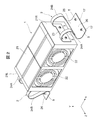
- FIG. 1 is a perspective view showing a state in which a fan device according to Embodiment 1 of the present invention is attached to a casing of an electronic device
- FIG. 2 is an enlarged view of the fan device shown in FIG. 1 and its attachment structure
- 3 is a front view showing the fan device shown in FIG. 1 and its mounting structure
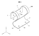
- FIG. 4 is a perspective view showing a leaf spring for attaching the fan device shown in FIG. 1 to the housing
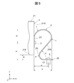
- FIG. 1 is an enlarged front view showing a part of the fan device and its mounting structure shown in FIG. 1
- FIG. 6 is a right side view of the leaf spring shown in FIG.
- the thickness, size, enlargement / reduction ratio, etc. of each member are not matched with the actual ones. Also,
- the fan device 1 is disposed, for example, in a housing 4 of an electronic device, and has a flow direction (airflow blown out by the fan device 1).
- Direction in the first embodiment, two fans 22 mounted in series with respect to the direction opposite to the Z direction) and two fans 22 mounted in parallel with the flow path direction, and these four fans And a fan case 21 having a built-in fan 22 therein.
- Embodiment 1 demonstrates the case where the four fans 22 are mounted in the fan case 21, not only this but the fan case 21 should just be a case which can mount one or more fans 22, A plurality of fans 22 may be mounted in the parallel direction and / or in the series direction with respect to the flow path direction, or may be a single unit.
- a hard disk drive 6 is disposed on the upstream or downstream side of the flow path direction of the housing 4, and the airflow sucked into the fan device 1 or the airflow blown from the fan device 1 passes through the hard disk drive 6. Or by hitting the hard disk drive 6, the hard disk drive 6 is cooled.
- leaf spring 2 One end of the leaf spring 2 is attached to the side walls 21R and 21L substantially parallel to the flow path of the fan case 21, and the other end of the leaf spring 2 is attached to the bottom surface 4F of the housing 4. Since the pair of leaf springs 2 attached to the side walls 21R and 21L are the same leaf spring 2, the leaf spring 2 attached to the side wall 21R will be described here.
- the leaf spring 2 includes a plate-like fan device side mounting portion 23 (corresponding to the first mounting portion of the present invention) attached to the side wall 21R of the fan case 21.
- the fan device side mounting portion 23 continuously extends from both ends in the Z direction, bends at a bending radius c (inflection point c: see FIG. 5), and further has a bending radius f (inflection point f: see FIG. 5).
- the curved strip-shaped curved portions 24A and 24B (corresponding to the first curved portion of the present invention) and one end of the strip-shaped curved portions 24A and 24B are continuously provided at both ends in the Z direction, and the bending radius e (inflection point) e: see FIG.
- the housing side bending portion 25 (corresponding to the second bending portion of the present invention) and the housing side bending portion 25 continuously extend from one end of the housing 4 to the bottom surface 4F of the housing 4.
- a plate-like housing-side mounting portion 26 (corresponding to the second mounting portion of the present invention) to be mounted; Eteiru.
- the leaf spring 2 is made of, for example, a metal material having elasticity having an optimum hardness as a spring material, such as stainless steel.
- the plate thickness of the leaf spring 2 is indicated by t.
- the band-shaped bending portions 24A and 24B and the housing-side bending portion 25 constitute the bending portion of the present invention.
- fan case connecting holes 7 for fixing the leaf spring 2 to the side wall 21R of the fan case 21 are formed.
- a screw 3 is inserted into the fan case connecting hole 7, and the screw 3 is screwed into a leaf spring connecting hole (not shown) formed in the side wall 21 ⁇ / b> R of the fan case 21.
- the attachment portion 23 is fixed to the side wall 21R.
- the length (width) in the Z direction of the fan device side mounting portion 23 is indicated by w.
- the band-shaped curved portions 24A and 24B have the same shape, and as shown in FIG. 5, the bending radius c is set so that the position of the distance g from the center of the fan case connecting hole 7 is the apex. It is further bent with a bending radius f so that the position at a distance h from the side wall 21R in the X direction is the apex. That is, the band-shaped curved portions 24A and 24B are formed so as to extend in the X direction from the side wall 21R when the leaf spring 2 is attached to the side wall 21R, but do not protrude from the Y direction end of the fan case 21. Has been. In FIG.
- the length (width) in the Z direction of the band-shaped curved portions 24A and 24B is indicated by m
- the distance between the band-shaped curved portion 24A and the band-shaped curved portion 24B is indicated by k
- the band-shaped curved portions 24A and 24B The distance from the apex to the housing side bending portion 25 is indicated by j
- the distance from the apex of the belt-like bending portions 24A and 24B to the fan device side attaching portion 23 is indicated by i.
- the housing-side bending portion 25 is bent with a bending radius e so that an angle formed by the belt-like bending portions 24A and 24B and the housing-side mounting portion 26 is d.
- the casing-side bending portion 25 is formed so as not to contact the side wall 21R when the leaf spring 2 is attached to the side wall 21R.
- housing connecting holes 8 for fixing the leaf spring 2 to the bottom surface 4F of the housing 4 are formed.
- the case connecting hole 8 is formed at a position where the distance from the center to the side wall 21R becomes a when the case side attaching portion 26 is attached to the bottom surface 4F.
- a screw 5 is inserted into the housing connecting hole 8, and the screw 5 is screwed into a fastener 17 press-fitted to the bottom surface 4 F of the housing 4, so that it is fixed to the bottom surface 4 F of the housing 4. It has become.
- the housing-side attachment portion 26 is attached to the bottom surface 4F, the bottom surface 21F of the fan case 21 is separated from the bottom surface 4F of the housing 4 by a distance p.
- the length (width) in the Z direction of the housing-side mounting portion 26 is indicated by w, and this width is the same as the width of the housing-side bending portion 25 in the first embodiment.
- the fan device side mounting portions 23 are respectively fixed to the side walls 21 ⁇ / b> R and 21 ⁇ / b> L, and extend and bend to the outside of the fan device 1. Since it is attached to the housing 4 via the leaf spring 2 attached outside the fan device arrangement region, the vibration generated from the fan device 1 during driving can be absorbed by the leaf spring 2.
- the leaf spring 2 is curved at the inflection point c, the inflection point f, and the inflection point e (curved in a substantially S shape when viewed from the front), so that the fan case 21 as a vibration transmission source and the vibration
- the vibration transmission path connecting the housing 4 that is the transmission destination can be made long, and the fan case 21 and the housing 4 are not in direct contact (non-contact). It is possible to sufficiently suppress vibrations and vibrations in all axial rotation directions from being transmitted to the housing 4.
- the vibration transmission path length when the leaf spring 2 is used is 2.04x.
- the screw 5 inserted into the housing connection hole 8 is screwed to the fastener 17 press-fit to the bottom surface 4F of the housing 4 so that the leaf spring 2 is attached to the bottom surface 4F of the housing 4.
- the present invention is not limited to this, and the case-side attachment portion 26 has the screw 5 inserted into the case connection hole 8 formed on the bottom surface 4F of the case 4. You may fix by screwing directly in a screw hole etc.
- the number of the leaf springs 2 can be arbitrarily determined according to the length of the fan device 1 in the Z direction, such as two or more pairs.
- FIG. 7 is a perspective view showing the fan device and its mounting structure according to Embodiment 2 of the present invention.
- the same members as those described in the first embodiment are denoted by the same reference numerals, and detailed description thereof is omitted.
- FIG. 8 is a perspective view showing a fan device and its mounting structure according to Embodiment 3 of the present invention.
- the same members as those described in the first embodiment are denoted by the same reference numerals, and detailed description thereof is omitted.
- the fan device mounting structure according to the third embodiment is different from the fan device mounting structure according to the first embodiment in the shape and number of the leaf springs 2. That is, as shown in FIG. 8, the leaf spring 2 according to the third embodiment includes a plate-like fan device side mounting portion 33 that is attached to the side wall 21 ⁇ / b> R of the fan case 21, and a central portion in the Z direction of the fan device side mounting portion 33.
- a belt-like curved portion 34 that continuously extends from the curved portion, curves at a bending radius c (inflection point c: see FIG. 5), and further curves at a bending radius f (inflection point f: see FIG. 5), and a belt-like curved portion.
- housing side bending portion 35 curved at a bending radius e (inflection point e: see FIG. 5), and one end of the housing side bending portion 35 are continuously provided in the center in the Z direction.
- a plate-like housing side attachment portion 36 attached to the bottom surface 4F of the housing 4.
- the fan device side mounting portion 33 is the same as that of the first embodiment. Similarly, it is fixed to the side wall 21 ⁇ / b> R by a screw 3.
- the belt-shaped curved portion 34 is formed such that the length (width) m in the Z direction is shorter (narrower) than the length (width) in the same direction of the fan device side mounting portion 33, and the same direction of the housing side curved portion 35. Is formed to be the same as the length (width) m of the belt-like curved portion 34.
- the length (width) m of the belt-like curved portion 34 is the same as that of the belt-like curved portions 24A and 24B described in the first embodiment, but the length (width) m is the same as the fan device 1.
- the resonance phenomenon occurs as much as possible at the rotational speed of the fan 22 in consideration of the mass and natural frequency of the housing, the natural frequency of the housing 4, the natural frequency of the hard disk drive 6, the mounting space of the leaf spring 2, the manufacturing cost, etc. You can decide not to.
- the leaf springs 2 are mounted in two (two pairs) on the side walls 21R and 21L, two at a predetermined interval in the Z direction. As in the first embodiment, the spring 2 extends and curves outside the fan device 1, and the housing-side attachment portion 26 is attached outside the fan device arrangement region on the bottom surface 4 ⁇ / b> F of the housing 4. The vibration generated from the fan device 1 can be absorbed by the leaf spring 2.
- the leaf spring 2 is curved at the inflection point c, the inflection point f, and the inflection point e (curved in a substantially S shape when viewed from the front), so that the fan case 21 as a vibration transmission source and the vibration
- the vibration transmission path connecting the housing 4 that is the transmission destination can be made long, and the fan case 21 and the housing 4 are not in direct contact (non-contact). It is possible to sufficiently suppress vibrations and vibrations in all axial rotation directions from being transmitted to the housing 4.
- the fan device side mounting portion 33, the housing side bending portion 35, and the housing side mounting portion 36 are formed narrower than the leaf spring 2 described in the first embodiment. Therefore, the material cost can be reduced and the space saving can be improved. In addition, a space for arranging a desired element can be secured between the leaf springs 2 arranged side by side.
- the number of the leaf springs 2 can be arbitrarily determined according to the length of the fan device 1 in the Z direction, such as one pair or three or more pairs.
- FIG. 9 is a perspective view showing a fan device and its mounting structure according to Embodiment 4 of the present invention.
- the same members as those described in the third embodiment are denoted by the same reference numerals, and detailed description thereof is omitted.
- the fan device mounting structure according to the fourth embodiment is different from the fan device mounting structure according to the third embodiment in the shape of the leaf spring 2. That is, in the leaf spring 2 according to the fourth embodiment, the length (width) in the Z direction of the belt-like curved portion 34 is larger than the length (width) in the Z direction of the belt-like curved portion 34 of the leaf spring 2 according to the third embodiment. Is also short (narrow). In other words, the leaf spring 2 according to the fourth embodiment is formed such that the length (width) in the Z direction of the belt-shaped curved portion 34 is shorter (narrower) than the length (width) in the same direction of the housing-side curved portion 35. ing.
- FIG. 10 is a perspective view showing a fan device and its mounting structure according to Embodiment 5 of the present invention.
- the same members as those described in the third embodiment are denoted by the same reference numerals, and detailed description thereof is omitted.
- the fan device mounting structure according to the fifth embodiment is different from the fan device mounting structure according to the third embodiment in the shape of the leaf spring 2. That is, the leaf spring 2 according to the fifth embodiment has a bellows shape formed in the belt-like curved portion 44. With this bellows shape, the inflection points of the band-shaped curved portion 44 can be increased efficiently, and the vibration transmission path connecting the fan case 21 that is the vibration transmission source and the housing 4 that is the vibration transmission destination is made even longer. Therefore, it is possible to further sufficiently suppress the vibration in the entire translation direction and the vibration in the entire axial rotation direction generated from the fan device 1 from being transmitted to the housing 4.
- FIG. 11 is a perspective view showing a fan device and its mounting structure according to Embodiment 6 of the present invention.
- the same members as those described in the fifth embodiment are denoted by the same reference numerals, and detailed description thereof is omitted.
- the fan device mounting structure according to the sixth embodiment is different from the fan device mounting structure according to the fifth embodiment in the shape of the leaf spring 2. That is, the leaf spring 2 according to the sixth embodiment is formed by bending the bellows shape formed in the belt-like curved portion 44 instead of being curved. Similarly to the fifth embodiment, this bellows shape is also generated from the fan device 1 because the vibration transmission path connecting the fan case 21 that is the vibration transmission source and the housing 4 that is the vibration transmission destination can be made even longer. It is possible to further sufficiently suppress the vibration in the entire translation direction and the vibration in the entire axial rotation direction from being transmitted to the housing 4.
- FIG. 12 is a perspective view showing a fan device and its mounting structure according to Embodiment 7 of the present invention.
- the same members as those described in the third embodiment are denoted by the same reference numerals, and detailed description thereof is omitted.
- the fan device mounting structure according to the seventh embodiment is different from the fan device mounting structure according to the third embodiment in the shape of the leaf spring 2. That is, in the leaf spring 2 according to the seventh embodiment, the length (width) in the Z direction of the fan device side mounting portion 43 and the housing side mounting portion 46 is the same as that of the fan device side mounting portion 33 and the housing side mounting according to the third embodiment.
- the portion 36 is formed shorter (narrower) than the length (width) in the Z direction.
- the material cost can be reduced and the space saving can be improved by making the length (width) shorter than the length (width) in the Z direction of the fan device side mounting portion 33 and the housing side mounting portion 36. can do. Further, a space for arranging a desired element can be secured between the leaf springs 2 arranged side by side.
- the shapes of the fan device side mounting portion 33 and the housing side mounting portion 36 can be applied to the leaf spring 2 having the configuration described in the fifth and sixth embodiments.
- FIG. 13 is a perspective view which shows the fan apparatus which concerns on Embodiment 8 of this invention, and its attachment structure.
- the same members as those described in the third embodiment are denoted by the same reference numerals, and detailed description thereof is omitted.
- the difference of the fan device mounting structure according to the eighth embodiment from the fan device mounting structure according to the third embodiment is the shape of the leaf spring 2. That is, in the leaf spring 2 according to the eighth embodiment, the length (width) in the Z direction is the same in all of the fan device side mounting portion 53, the band-shaped bending portion 34, the housing side bending portion 35, and the housing side mounting portion 56. It is formed to become.
- the material cost can be further reduced and the space saving can be further improved.
- a space for arranging a desired element can be secured between the leaf springs 2 arranged side by side.
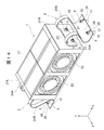
- FIG. 14 is a perspective view showing a fan device and its mounting structure according to Embodiment 9 of the present invention
- FIG. 15 is an enlarged cross-sectional view showing a part of the mounting structure shown in FIG. 14, and
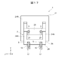
- FIG. 17 is a cross-sectional view taken along line AA shown in FIG. 16, and
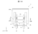
- FIG. 18 is a right side of the fan device shown in FIG. 14 and its mounting structure.
- FIG. 19 is a sectional view taken along the line BB shown in FIG.
- the same members as those described in the first embodiment are denoted by the same reference numerals, and detailed description thereof is omitted.
- the fan device mounting structure according to the ninth embodiment is different from the fan device mounting structure according to the first embodiment in the shape of the leaf spring 2. That is, as shown in FIGS. 14 to 19, in the fan device side mounting portion 23 of the leaf spring 2 according to the ninth embodiment, the fan case connecting hole 7 communicates with the outside in a direction perpendicular to the screw insertion direction. A notch 27 is formed, and the casing-side mounting portion 26 is formed with a notch 28 for allowing the casing connecting hole 8 to communicate with the outside in a direction perpendicular to the screw insertion direction.
- a cylindrical bush 9 (corresponding to the elastic member of the present invention) is disposed at a position where the fan case connecting hole 7 of the fan device side mounting portion 23 is formed so as to sandwich both surfaces thereof.
- a cylindrical bush 10 is disposed at a position where the housing connection hole 8 of the housing side mounting portion 26 is formed so as to sandwich both surfaces thereof.
- the bushes 9 and 10 can be formed of a material different from that of the leaf spring 2, for example, an elastic material such as rubber or resin.
- the bush 10 has a groove 101 having a width substantially the same as the plate thickness t of the housing-side mounting portion 26 formed in the center portion in the axial direction along the outer periphery thereof. Further, a hole 102 through which the screw 5 (screw 3 in the case of the bush 9) can be inserted is formed through the bush 10. The bush 10 is inserted from the notch 28 at a position where the housing connecting hole 8 and the hole 102 coincide. The housing-side mounting portion 26 is fixed to the bottom surface 4F of the housing 4 by screwing the screw 5 inserted into the hole 102 and the housing connecting hole 8 into the fastener 17. The bush 9 is also inserted from the notch 27 and attached to the fan device side attachment portion 23 in the same manner.
- the vibration suppressing effect by the elastic force of the bushes 9 and 10 can be obtained. 4 can be more reliably suppressed.
- the bushes 9 and 10 are only required to be formed of an elastic material that is different from the leaf spring 2, and the hardness, thickness, size, and the like thereof are determined based on the mass and natural frequency of the fan device 1 and the housing 4. In consideration of the natural frequency, the natural frequency of the hard disk drive 6, the mounting space of the leaf spring 2, the manufacturing cost, etc., it is determined so that the resonance phenomenon does not occur as much as possible at the rotational speed of the fan 22 to be used.
- the bushes 9 and 10 can be applied to the leaf spring 2 described in the other embodiments.
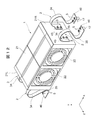
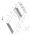
- FIG. 20 is a perspective view showing a state in which the fan device according to Embodiment 10 of the present invention is attached to the casing of the electronic device
- FIG. 21 is an enlarged view of the right side of the fan device shown in FIG. 20 and its mounting structure
- FIG. 22 is an enlarged perspective view showing the left side of the fan device and its mounting structure shown in FIG.
- the same members as those described in the first embodiment are denoted by the same reference numerals, and detailed description thereof is omitted.
- the fan device mounting structure according to the tenth embodiment differs from the fan device mounting structure according to the first embodiment in that five fan devices 1 are arranged in the X direction and two in the Z direction.
- the shape of the leaf spring 2 and the other end of the leaf spring 2 are fixed to the side walls 4R and 4L of the housing 4 via relay members 11 and 12, respectively.
- the relay member 11 is fixed by a screw 14 inside one side wall 4R in the X direction, and the relay member 12 is fixed by a screw 16 inside the other side wall 4L.
- the relay members 11 and 12 extend inside the housing 4, and the housing mounting portion 66 of the leaf spring 2 is fixed by the screw 13. That is, the relay members 11 and 12 are interposed between the housing-side mounting portion 66 of the leaf spring 2 and the side walls 4R and 4L of the housing 4, and play a role of filling (relaying) between the two. Therefore, although the length of the part extended inside the housing
- the plate spring 2 includes a plate-like fan device side mounting portion 63 attached to the side wall 21 ⁇ / b> R of the fan case 21 and a housing continuously from both ends of the fan device side mounting portion 63 in the Z direction.
- the band-shaped curved portions 64A and 64B each extending toward the bottom surface 4F side of the body 4 and curving in a substantially U shape, and one ends of the strip-shaped curved portions 64A and 64B are continuously provided at both ends in the Z direction, and substantially L
- a housing-side bending portion 65 that curves in a letter shape, and a plate-like housing-side mounting portion 66 that continuously extends from one end of the housing-side bending portion 65 and is attached to the relay member 11 are provided.
- the fan device side mounting portion 63 is fixed to the side wall 21 ⁇ / b> R by a screw similarly to the fan device side mounting portion 23 according to the first embodiment.
- the strip-shaped curved portions 64A and 64B have the same shape, and are formed so as not to contact the housing 4 when the leaf spring 2 supports the fan device 1.
- the length (width) in the Z direction of the belt-shaped curved portions 64A and 64B is the same as that of the belt-shaped curved portions 24A and 24B described in the first embodiment, but this length (width) m is In consideration of the mass and natural frequency of the fan device 1, the natural frequency of the housing 4, the natural frequency of the hard disk drive 6, the mounting space of the leaf spring 2, the manufacturing cost, etc. It can be determined that the phenomenon does not occur as much as possible.
- the housing-side bending portion 65 is continuously formed at the tips of the band-shaped bending portions 64A and 64B, and has the same length (width) in the Z direction as the band-shaped bending portions 64A and 64B.
- the housing-side mounting portion 66 is formed continuously at the tip of each housing-side bending portion 65, and has a length (width) in the Z direction longer than that of the housing-side bending portion 65.
- a housing connection hole (not shown) for fixing the leaf spring 2 to the relay member 11 is formed in the housing side mounting portion 66, and the inserted screw 13 is formed in the relay member 11. It is fixed to the side wall 4 ⁇ / b> R of the housing 4 via the relay member 11 by being screwed into a screw hole (not shown).
- the fan device side mounting portions 63 are respectively fixed to the side walls 21 ⁇ / b> R and 21 ⁇ / b> L, extend to the outside of the fan device 1, and are curved, and the housing side mounting portion 66 is the fan device arrangement of the housing 4. Since it is attached to the side walls 4R and 4L of the housing 4 via the leaf spring 2 attached to the outside of the region, the vibration generated from the fan device 1 during driving can be absorbed by the leaf spring 2. At this time, since the leaf spring 2 has a plurality of inflection points, the vibration transmission path connecting the fan case 21 that is the vibration transmission source and the housing 4 that is the vibration transmission destination can be long. Since the fan case 21 and the housing 4 are not in direct contact (non-contact), it is sufficient that the vibration in all translation directions and the vibration in all shaft rotation directions generated from the fan device 1 are transmitted to the housing 4. Can be suppressed.
- relay members 11 and 12 may not necessarily be provided depending on the distance between the case-side attachment portion 66 and the side walls 4R and 4L of the case 4, or only one of them may be provided.
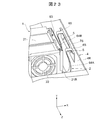
- FIG. 23 is an enlarged perspective view showing the right side of the fan device and its mounting structure according to Embodiment 11 of the present invention.
- the same members as those described in the first embodiment are denoted by the same reference numerals, and detailed description thereof is omitted.
- the fan device mounting structure according to the eleventh embodiment is different from the fan device mounting structure according to the tenth embodiment in the shape of the leaf spring 2. That is, in the leaf spring 2 according to the eleventh embodiment, as shown in FIG. 23, instead of providing the relay member 11, the shape of the housing side mounting portion 76 is changed to the relay member 11 and the housing side mounting portion according to the tenth embodiment. 66 is formed into an integrated shape.
- the casing-side mounting portion 76 has a shape in which the relay member 12 and the casing-side mounting portion 66 according to the tenth embodiment are integrated. You may form in.
- the present invention is not limited to this, and depending on the shape and type of the fan 22 Instead of mounting the fan 22 on the fan case 21, the fan 22 itself may be attached to the housing 4 by the leaf spring 2.
- the fan device 1 can be attached to a desired position such as the ceiling surface of the housing 4 in addition to the bottom surface 4F and the side walls 4R and 4L of the housing 4.
Landscapes
- Engineering & Computer Science (AREA)
- General Engineering & Computer Science (AREA)
- Mechanical Engineering (AREA)
- Computer Hardware Design (AREA)
- Physics & Mathematics (AREA)
- Thermal Sciences (AREA)
- Microelectronics & Electronic Packaging (AREA)
- Structures Of Non-Positive Displacement Pumps (AREA)
- Cooling Or The Like Of Electrical Apparatus (AREA)
Abstract
Description
図1は、本発明の実施形態1に係るファン装置が電子機器の筐体に取付された状態を示す斜視図、図2は、図1に示すファン装置と及びその取付構造を拡大して示す斜視図、図3は、図1に示すファン装置とその取付構造を示す正面図、図4は、図1に示すファン装置を筐体に取付けるための板バネを示す斜視図、図5は、図1に示すファン装置とその取付構造の一部を拡大して示す正面図、図6は、図4に示す板バネの右側面図である。なお、前記各図では、説明を判り易くするため、各部材の厚さやサイズ、拡大・縮小率等は、実際のものとは一致させずに記載した。また、
次に、本発明の実施形態2に係るファン装置及びその取付構造について図面を参照して説明する。図7は、本発明の実施形態2に係るファン装置とその取付構造を示す斜視図である。なお、実施形態2では、実施形態1で説明した部材と同一の部材には、同一の符号を付し、その詳細な説明は省略する。
次に、本発明の実施形態3に係るファン装置及びその取付構造について図面を参照して説明する。図8は、本発明の実施形態3に係るファン装置とその取付構造を示す斜視図である。なお、実施形態3では、実施形態1で説明した部材と同一の部材には、同一の符号を付し、その詳細な説明は省略する。
次に、本発明の実施形態4に係るファン装置及びその取付構造について図面を参照して説明する。図9は、本発明の実施形態4に係るファン装置とその取付構造を示す斜視図である。なお、実施形態4では、実施形態3で説明した部材と同一の部材には、同一の符号を付し、その詳細な説明は省略する。
次に、本発明の実施形態5に係るファン装置及びその取付構造について図面を参照して説明する。図10は、本発明の実施形態5に係るファン装置とその取付構造を示す斜視図である。なお、実施形態5では、実施形態3で説明した部材と同一の部材には、同一の符号を付し、その詳細な説明は省略する。
次に、本発明の実施形態6に係るファン装置及びその取付構造について図面を参照して説明する。図11は、本発明の実施形態6に係るファン装置とその取付構造を示す斜視図である。なお、実施形態6では、実施形態5で説明した部材と同一の部材には、同一の符号を付し、その詳細な説明は省略する。
次に、本発明の実施形態7に係るファン装置及びその取付構造について図面を参照して説明する。図12は、本発明の実施形態7に係るファン装置とその取付構造を示す斜視図である。なお、実施形態7では、実施形態3で説明した部材と同一の部材には、同一の符号を付し、その詳細な説明は省略する。
次に、本発明の実施形態8に係るファン装置及びその取付構造について図面を参照して説明する。図13は、本発明の実施形態8に係るファン装置とその取付構造を示す斜視図である。なお、実施形態8では、実施形態3で説明した部材と同一の部材には、同一の符号を付し、その詳細な説明は省略する。
次に、本発明の実施形態9に係るファン装置及びその取付構造について図面を参照して説明する。図14は、本発明の実施形態9に係るファン装置とその取付構造を示す斜視図、図15は、図14に示す取付構造の一部を拡大して示す断面図、図16は、図14に示すファン装置とその取付構造の一部を示す平面図、図17は、図16に示すA-A線に沿った断面図、図18は、図14に示すファン装置とその取付構造の右側面図、図19は、図18に示すB-B線に沿った断面図である。なお、実施形態9では、実施形態1で説明した部材と同一の部材には、同一の符号を付し、その詳細な説明は省略する。
次に、本発明の実施形態10に係るファン装置及びその取付構造について図面を参照して説明する。図20は、本発明の実施形態10に係るファン装置が電子機器の筐体に取付られた状態を示す斜視図、図21は、図20に示すファン装置とその取付構造の右側を拡大して示す斜視図、図22は、図20に示すファン装置とその取付構造の左側を拡大して示す斜視図である。なお、実施形態10では、実施形態1で説明した部材と同一の部材には、同一の符号を付し、その詳細な説明は省略する。
次に、本発明の実施形態11に係るファン装置及びその取付構造について図面を参照して説明する。図23は、本発明の実施形態11に係るファン装置とその取付構造の右側を拡大して示す斜視図である。なお、実施形態10では、実施形態1で説明した部材と同一の部材には、同一の符号を付し、その詳細な説明は省略する。
21…ファンケース、21L、21R…側壁、22…ファン、23、33、43、53、63…ファン装置側取付部、24A、24B、34、44、64A、64B…帯状湾曲部、25、35、65…筐体側湾曲部、26、36、46、56、66…筐体側取付部
Claims (12)
- ファン装置と、
前記ファン装置が搭載される筐体と、
一端が前記ファン装置に取付けられると共に、当該ファン装置の外側に延出して湾曲し、他端が前記筐体の当該ファン装置配置領域よりも外側に取付けられる少なくとも一対の板バネと、
を備え、
前記ファン装置は、互いに対向する両面が前記各々の板バネにそれぞれ支持されると共に、前記筐体と離間して取付けられてなるファン装置の取付構造。 - 前記板バネは、複数の変曲点を有する請求項1記載のファン装置の取付構造。
- 前記板バネは、
前記ファン装置に取付けられる第1の取付部と、
前記筐体に取付けられる第2の取付部と、
前記第1の取付部から延出し、当該第1の取付部と前記第2の取付部との間に介在すると共に、複数の変曲点を有する湾曲部と、
を備えた請求項1記載のファン装置の取付構造。 - 前記湾曲部は、
前記第1の取付部から延出する第1の湾曲部と、
前記第1の湾曲部と前記第2の取付部との間に介在する第2の湾曲部と、
を備えた請求項3記載のファン装置の取付構造。 - 前記第1の湾曲部を2つ備え、当該両第1の湾曲部は、前記第1の取付部より幅が狭い帯状の湾曲部からなり、
一方の第1の湾曲部は、前記第1の取付部の幅方向の一端部から延出し、
他方の第1の湾曲部は、前記第1の取付部の幅方向の他端部から延出し、
前記第2の湾曲部は、前記第2の取付部と同じ幅を有し、前記一方の第1の湾曲部の延出端は、当該第2の湾曲部の幅方向の一端部に位置し、前記他方の第1の湾曲部の延出端は、当該第2の湾曲部の幅方向の他端部に位置する請求項4記載のファン装置の取付構造。 - 前記第1の湾曲部は、前記第1の取付部より幅が狭い帯状の湾曲部からなり、
前記第2の湾曲部は、当該第1の湾曲部と同じ幅であり、且つ前記第2の取付部より幅が狭い請求項4記載のファン装置の取付構造。 - 前記第1の湾曲部は、前記第1の取付部より幅が狭い帯状の湾曲部からなり、
前記第2の湾曲部は、当該第1の湾曲部より幅が広く、且つ前記第2の取付部より幅が狭い請求項4記載のファン装置の取付構造。 - 前記湾曲部は蛇腹形状を有する請求項3記載のファン装置の取付構造。
- 前記第1の取付部の幅、前記第1の湾曲部の幅、前記第2の湾曲部の幅、前記第2の取付部の幅が、同一である請求項4記載のファン装置の取付構造。
- 前記第1の取付部を前記ファン装置に螺子止めするための螺子穴を当該第1の取付部に形成し、当該第1の取付部の螺子挿入方向両面に、前記螺子穴に挿入された螺子が貫通すると共に、前記板バネとは異なる材質の弾性部材を配設した請求項3記載のファン装置の取付構造。
- 前記第2の取付部を前記ファン装置に螺子止めするための螺子穴を当該第2の取付部に形成し、当該第2の取付部の螺子挿入方向両面に、前記螺子穴に挿入された螺子が貫通すると共に、前記板バネとは異なる材質の弾性部材を配設した請求項3記載のファン装置の取付構造。
- 前記第1の取付部及び前記第2の取付部の少なくとも一方が、前記筐体に中継部品を介して取付けられる請求項3記載のファン装置の取付構造。
Priority Applications (4)
| Application Number | Priority Date | Filing Date | Title |
|---|---|---|---|
| US14/126,032 US9593695B2 (en) | 2011-06-16 | 2011-06-16 | Fan device attachment structure |
| CN201180071669.4A CN103608594B (zh) | 2011-06-16 | 2011-06-16 | 风扇装置的安装构造 |
| JP2013520327A JP5809698B2 (ja) | 2011-06-16 | 2011-06-16 | ファン装置の取付構造 |
| PCT/JP2011/003454 WO2012172614A1 (ja) | 2011-06-16 | 2011-06-16 | ファン装置の取付構造 |
Applications Claiming Priority (1)
| Application Number | Priority Date | Filing Date | Title |
|---|---|---|---|
| PCT/JP2011/003454 WO2012172614A1 (ja) | 2011-06-16 | 2011-06-16 | ファン装置の取付構造 |
Publications (1)
| Publication Number | Publication Date |
|---|---|
| WO2012172614A1 true WO2012172614A1 (ja) | 2012-12-20 |
Family
ID=47356642
Family Applications (1)
| Application Number | Title | Priority Date | Filing Date |
|---|---|---|---|
| PCT/JP2011/003454 WO2012172614A1 (ja) | 2011-06-16 | 2011-06-16 | ファン装置の取付構造 |
Country Status (4)
| Country | Link |
|---|---|
| US (1) | US9593695B2 (ja) |
| JP (1) | JP5809698B2 (ja) |
| CN (1) | CN103608594B (ja) |
| WO (1) | WO2012172614A1 (ja) |
Cited By (4)
| Publication number | Priority date | Publication date | Assignee | Title |
|---|---|---|---|---|
| WO2016056291A1 (ja) * | 2014-10-08 | 2016-04-14 | ヘルツ株式会社 | 防振装置 |
| JP2016223507A (ja) * | 2015-05-29 | 2016-12-28 | ヘルツ株式会社 | 防振装置 |
| CN112253511A (zh) * | 2020-11-18 | 2021-01-22 | 江苏恒康机电有限公司 | 一种安装稳定防止松动的防爆风机 |
| WO2023085301A1 (ja) * | 2021-11-11 | 2023-05-19 | 株式会社不二工機 | 排水ポンプ |
Families Citing this family (7)
| Publication number | Priority date | Publication date | Assignee | Title |
|---|---|---|---|---|
| US10641293B2 (en) * | 2016-09-20 | 2020-05-05 | Dell Products L.P. | Fan suspension system to provide vibration isolation, secure mounting, and thermal seal |
| CN106369799A (zh) * | 2016-10-18 | 2017-02-01 | 广东美的暖通设备有限公司 | 用于空调器排水泵的支架组件和空调器 |
| CN107317453B (zh) * | 2017-06-07 | 2019-06-28 | 浙江省东阳市东磁诚基电子有限公司 | 一种可使线性马达沿x轴或z轴振动的马达弹性结构 |
| US11143268B2 (en) | 2018-06-13 | 2021-10-12 | Raytheon Company | Vibration isolation system with thermal growth compensation |
| DE102020201618A1 (de) * | 2020-02-10 | 2021-08-12 | Willbrandt Kg | Geräte- und Anti-Schocklager und Geräte- und Anti-Schocklageranordnung |
| CN113357178A (zh) * | 2021-07-13 | 2021-09-07 | 阳光电源股份有限公司 | 一种风扇组件及逆变器 |
| US20230027815A1 (en) * | 2021-07-23 | 2023-01-26 | Nokia Shanghai Bell Co., Ltd. | Vibration isolation to protect electrical circuits from vibration-induced damage |
Citations (6)
| Publication number | Priority date | Publication date | Assignee | Title |
|---|---|---|---|---|
| JPH01159565U (ja) * | 1988-04-19 | 1989-11-06 | ||
| JP2002340090A (ja) * | 2001-05-17 | 2002-11-27 | Matsushita Electric Ind Co Ltd | 防振装置 |
| JP2006216678A (ja) * | 2005-02-02 | 2006-08-17 | Denso Corp | 半導体用の放熱器 |
| JP2008031980A (ja) * | 2006-07-26 | 2008-02-14 | Giga-Byte Technology Co Ltd | ファンの固定装置 |
| JP2008130766A (ja) * | 2006-11-20 | 2008-06-05 | Sharp Corp | 支持具付きファン、ファン及び映像表示装置 |
| JP2010043575A (ja) * | 2008-08-11 | 2010-02-25 | Nippon Keiki Works Ltd | 表面実装用超小形ファンモータ |
Family Cites Families (17)
| Publication number | Priority date | Publication date | Assignee | Title |
|---|---|---|---|---|
| JP3166233B2 (ja) * | 1991-09-26 | 2001-05-14 | 松下電器産業株式会社 | 電気掃除機 |
| JPH07263877A (ja) | 1994-03-18 | 1995-10-13 | Matsushita Electric Works Ltd | 電子部品支持具 |
| JPH10145079A (ja) * | 1996-11-12 | 1998-05-29 | Sony Corp | 電子機器筐体の不要輻射電磁波のシールド構造 |
| KR100322468B1 (ko) | 1997-02-12 | 2002-04-22 | 윤종용 | 컴퓨터의팬고정장치와컴퓨터의팬고정장치를사용하는휴대용컴퓨터 |
| JP3602769B2 (ja) | 2000-04-28 | 2004-12-15 | 北川工業株式会社 | ファンユニット取り付け具及びファンユニット取り付け構造 |
| TW488532U (en) * | 2000-11-23 | 2002-05-21 | Hon Hai Prec Ind Co Ltd | Fixing frame of fan |
| TW578995U (en) * | 2003-01-22 | 2004-03-01 | Hon Hai Prec Ind Co Ltd | Fixing assembly for multi-fan |
| US7896610B2 (en) * | 2004-08-04 | 2011-03-01 | Inventec Corporation | Three-dimensionally vibration-preventing buffering mechanism |
| KR100693349B1 (ko) * | 2005-04-08 | 2007-03-09 | 삼성전자주식회사 | 광학 프로젝션 시스템용 dmd 조립체 |
| EP1972827B1 (en) * | 2006-01-10 | 2010-05-26 | Sintokogio, Ltd. | Multi-leaf spring type vibration damping device |
| JP4974530B2 (ja) * | 2006-01-18 | 2012-07-11 | 株式会社日立製作所 | ファン用モータサポートフレーム |
| DE202006009355U1 (de) * | 2006-06-13 | 2006-09-07 | Pfannenberg Gmbh | Filterlüfter mit einer Schnellbefestigungseinrichtung |
| US7379300B1 (en) * | 2007-02-07 | 2008-05-27 | Inventec Corporation | Fixing mechanism for a fan fixing frame |
| JPWO2009110085A1 (ja) * | 2008-03-06 | 2011-07-14 | パイオニア株式会社 | ファンモータの取付構造 |
| JP5200880B2 (ja) | 2008-11-19 | 2013-06-05 | ソニー株式会社 | 電子機器用送風装置及び電子機器 |
| CN101742876B (zh) * | 2008-11-21 | 2012-07-04 | 英业达股份有限公司 | 组合式风扇框架 |
| DE102010016503B4 (de) * | 2010-04-19 | 2013-10-24 | Rittal Gmbh & Co. Kg | Luftführungseinheit |
-
2011
- 2011-06-16 US US14/126,032 patent/US9593695B2/en active Active
- 2011-06-16 WO PCT/JP2011/003454 patent/WO2012172614A1/ja active Application Filing
- 2011-06-16 JP JP2013520327A patent/JP5809698B2/ja not_active Expired - Fee Related
- 2011-06-16 CN CN201180071669.4A patent/CN103608594B/zh active Active
Patent Citations (6)
| Publication number | Priority date | Publication date | Assignee | Title |
|---|---|---|---|---|
| JPH01159565U (ja) * | 1988-04-19 | 1989-11-06 | ||
| JP2002340090A (ja) * | 2001-05-17 | 2002-11-27 | Matsushita Electric Ind Co Ltd | 防振装置 |
| JP2006216678A (ja) * | 2005-02-02 | 2006-08-17 | Denso Corp | 半導体用の放熱器 |
| JP2008031980A (ja) * | 2006-07-26 | 2008-02-14 | Giga-Byte Technology Co Ltd | ファンの固定装置 |
| JP2008130766A (ja) * | 2006-11-20 | 2008-06-05 | Sharp Corp | 支持具付きファン、ファン及び映像表示装置 |
| JP2010043575A (ja) * | 2008-08-11 | 2010-02-25 | Nippon Keiki Works Ltd | 表面実装用超小形ファンモータ |
Cited By (5)
| Publication number | Priority date | Publication date | Assignee | Title |
|---|---|---|---|---|
| WO2016056291A1 (ja) * | 2014-10-08 | 2016-04-14 | ヘルツ株式会社 | 防振装置 |
| US10323713B2 (en) | 2014-10-08 | 2019-06-18 | Herz Co., Ltd. | Antivibration device |
| JP2016223507A (ja) * | 2015-05-29 | 2016-12-28 | ヘルツ株式会社 | 防振装置 |
| CN112253511A (zh) * | 2020-11-18 | 2021-01-22 | 江苏恒康机电有限公司 | 一种安装稳定防止松动的防爆风机 |
| WO2023085301A1 (ja) * | 2021-11-11 | 2023-05-19 | 株式会社不二工機 | 排水ポンプ |
Also Published As
| Publication number | Publication date |
|---|---|
| JP5809698B2 (ja) | 2015-11-11 |
| US20140234100A1 (en) | 2014-08-21 |
| US9593695B2 (en) | 2017-03-14 |
| JPWO2012172614A1 (ja) | 2015-02-23 |
| CN103608594A (zh) | 2014-02-26 |
| CN103608594B (zh) | 2017-02-08 |
Similar Documents
| Publication | Publication Date | Title |
|---|---|---|
| JP5809698B2 (ja) | ファン装置の取付構造 | |
| US8684707B2 (en) | Piezoelectric microblower | |
| KR100721906B1 (ko) | 팬 어셈블리 | |
| US8579269B2 (en) | Engine mount structure | |
| CN105790541B (zh) | 一种线性振动马达 | |
| US20060208614A1 (en) | Small piezoelectric air pumps with unobstructed airflow | |
| CN111786529A (zh) | 水平线性振动电机 | |
| CN111371248B (zh) | 旋转装置 | |
| JP2013223818A (ja) | 圧電アクチュエータ、電子機器 | |
| JP2010031659A (ja) | 直列式軸流ファン | |
| US8937813B2 (en) | Sub-rack mounting bracket and assembly | |
| US20140056693A1 (en) | Fan and fan frame thereof | |
| JPWO2009147784A1 (ja) | 基板の保持・固定構造 | |
| JP4857216B2 (ja) | ダイナミックダンパ | |
| JP6528456B2 (ja) | 電子機器筐体及び風制御板 | |
| JP2008133757A (ja) | 空気調和機 | |
| KR20220107276A (ko) | 와이어 스프링을 포함하는 선형 팬 | |
| JP4714567B2 (ja) | コネクタブラケット | |
| CN220107701U (zh) | 马达安装支架和空调室内机 | |
| JP2005241032A (ja) | 空気調和機 | |
| JP5698911B2 (ja) | スタビライザーブッシュ | |
| JP6559860B2 (ja) | 回転装置 | |
| JP2012022459A (ja) | 電子機器 | |
| KR101055553B1 (ko) | 압전모터 | |
| CN118539648A (zh) | 马达安装支架和空调室内机 |
Legal Events
| Date | Code | Title | Description |
|---|---|---|---|
| 121 | Ep: the epo has been informed by wipo that ep was designated in this application |
Ref document number: 11867630 Country of ref document: EP Kind code of ref document: A1 |
|
| ENP | Entry into the national phase |
Ref document number: 2013520327 Country of ref document: JP Kind code of ref document: A |
|
| NENP | Non-entry into the national phase |
Ref country code: DE |
|
| WWE | Wipo information: entry into national phase |
Ref document number: 14126032 Country of ref document: US |
|
| 122 | Ep: pct application non-entry in european phase |
Ref document number: 11867630 Country of ref document: EP Kind code of ref document: A1 |