WO2023085301A1 - 排水ポンプ - Google Patents
排水ポンプ Download PDFInfo
- Publication number
- WO2023085301A1 WO2023085301A1 PCT/JP2022/041658 JP2022041658W WO2023085301A1 WO 2023085301 A1 WO2023085301 A1 WO 2023085301A1 JP 2022041658 W JP2022041658 W JP 2022041658W WO 2023085301 A1 WO2023085301 A1 WO 2023085301A1
- Authority
- WO
- WIPO (PCT)
- Prior art keywords
- plate
- leg
- portions
- drainage pump
- main body
- Prior art date
Links
- 230000002093 peripheral effect Effects 0.000 claims description 8
- 230000000052 comparative effect Effects 0.000 description 11
- 230000004048 modification Effects 0.000 description 10
- 238000012986 modification Methods 0.000 description 10
- XLYOFNOQVPJJNP-UHFFFAOYSA-N water Substances O XLYOFNOQVPJJNP-UHFFFAOYSA-N 0.000 description 7
- 239000013256 coordination polymer Substances 0.000 description 6
- 210000000078 claw Anatomy 0.000 description 4
- 238000010586 diagram Methods 0.000 description 4
- 238000001816 cooling Methods 0.000 description 3
- 230000007423 decrease Effects 0.000 description 3
- 230000000694 effects Effects 0.000 description 3
- 238000001746 injection moulding Methods 0.000 description 3
- 238000004519 manufacturing process Methods 0.000 description 3
- 230000005540 biological transmission Effects 0.000 description 2
- 230000005484 gravity Effects 0.000 description 2
- 229920003002 synthetic resin Polymers 0.000 description 2
- 239000000057 synthetic resin Substances 0.000 description 2
- 238000009434 installation Methods 0.000 description 1
- 230000001629 suppression Effects 0.000 description 1
Images


Classifications
-
- F—MECHANICAL ENGINEERING; LIGHTING; HEATING; WEAPONS; BLASTING
- F04—POSITIVE - DISPLACEMENT MACHINES FOR LIQUIDS; PUMPS FOR LIQUIDS OR ELASTIC FLUIDS
- F04D—NON-POSITIVE-DISPLACEMENT PUMPS
- F04D1/00—Radial-flow pumps, e.g. centrifugal pumps; Helico-centrifugal pumps
- F04D1/14—Pumps raising fluids by centrifugal force within a conical rotary bowl with vertical axis
-
- F—MECHANICAL ENGINEERING; LIGHTING; HEATING; WEAPONS; BLASTING
- F04—POSITIVE - DISPLACEMENT MACHINES FOR LIQUIDS; PUMPS FOR LIQUIDS OR ELASTIC FLUIDS
- F04D—NON-POSITIVE-DISPLACEMENT PUMPS
- F04D29/00—Details, component parts, or accessories
- F04D29/40—Casings; Connections of working fluid
- F04D29/42—Casings; Connections of working fluid for radial or helico-centrifugal pumps
-
- F—MECHANICAL ENGINEERING; LIGHTING; HEATING; WEAPONS; BLASTING
- F04—POSITIVE - DISPLACEMENT MACHINES FOR LIQUIDS; PUMPS FOR LIQUIDS OR ELASTIC FLUIDS
- F04D—NON-POSITIVE-DISPLACEMENT PUMPS
- F04D29/00—Details, component parts, or accessories
- F04D29/60—Mounting; Assembling; Disassembling
- F04D29/62—Mounting; Assembling; Disassembling of radial or helico-centrifugal pumps
-
- F—MECHANICAL ENGINEERING; LIGHTING; HEATING; WEAPONS; BLASTING
- F04—POSITIVE - DISPLACEMENT MACHINES FOR LIQUIDS; PUMPS FOR LIQUIDS OR ELASTIC FLUIDS
- F04D—NON-POSITIVE-DISPLACEMENT PUMPS
- F04D29/00—Details, component parts, or accessories
- F04D29/66—Combating cavitation, whirls, noise, vibration or the like; Balancing
Definitions
- the present invention relates to a drainage pump.
- the air conditioner When the air conditioner is in cooling operation, the moisture in the air is cooled and condenses in the heat exchanger of the indoor unit, and the water droplets drip into the drain pan provided below the heat exchanger.
- the drain water accumulated in the drain pan is discharged to the outside through the drain pipe by gravity.
- a drainage pump is provided for draining water using a motor as a power source.
- Patent Document 1 discloses a drainage pump equipped with a motor.
- this drainage pump legs extending upward from the upper case are formed, and the drainage pump is attached to the structure by fastening the upper ends of the legs to the indoor unit of the air conditioner.
- the drainage pump of Patent Document 1 drains water by driving the rotating blades with a motor.
- vibration during drainage may propagate to the indoor unit via the legs of the drainage pump, causing resonance and noise.
- one idea is to interpose vibration-isolating rubber between the installation part of the indoor unit and the legs to make it difficult for the vibration of the drainage pump to propagate to the indoor unit side. is.
- anti-vibration rubber or the like is required to install the drainage pump, the cost of the parts will increase and the time and effort required to install the drainage pump will also increase.
- an object of the present invention is to provide a drainage pump that can suppress the propagation of vibrations without increasing the number of parts and is easy to install.
- a drainage pump having a case containing a rotating vane and a motor for rotationally driving the rotating vane,
- the case has a plurality of legs protruding along the rotation axis direction of the rotating blades,
- the leg has a leg main body fixed to a mounting portion, and a plurality of plate-like portions connecting the leg main body and the case,
- a first gap is formed between the case and the leg main body when viewed through the plate-like portion.
- FIG. 1 is a perspective view of a drainage pump according to a first embodiment
- FIG. FIG. 2 is a perspective view of the drainage pump according to the first embodiment
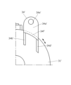
- FIG. FIG. 3 is a side view of the drainage pump shown attached to the mounting.
- FIG. 4 is a top view of the drainage pump.
- FIG. 5 is a side view of the drive unit shown removed from the housing.
- FIG. 6 is a side view of the drive unit shown removed from the housing.
- FIG. 7 is a perspective view similar to FIG. 1 of a drainage pump according to a comparative example.
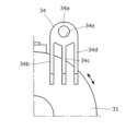
- FIG. 8 is an enlarged plan view of the second leg of the present embodiment along the rotation axis direction.
- FIG. 9 is an enlarged plan view of the second leg portion of the comparative example along the rotation axis direction.
- FIG. 8 is an enlarged plan view of the second leg of the present embodiment along the rotation axis direction.
- FIG. 10 is a graph comparing noise between this embodiment and a comparative example.
- FIG. 11 is a perspective view of a drive unit according to a second embodiment;
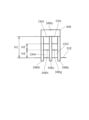
- FIG. 12 is a diagram of one of the leg portions of the drive unit in the modified example of the second embodiment, viewed from the outside along the radial direction.
- FIG. 13 is a diagram showing the relationship between the overall noise value (OA value) and the size of the first gap (H1-H2) when the drainage pump to which Modification 1 is applied is driven.
- FIG. 14 is a view similar to FIG. 12 according to another modification;
- FIG. 1 and 2 are perspective views of the drainage pump 1 according to the first embodiment of the present invention, but shown in different viewing directions.
- FIG. 3 is a side view of the drain pump 1 shown in an installed state.
- FIG. 4 is a top view of the drainage pump 1.
- the drainage pump 1 has a drive unit 3 containing a motor, and a synthetic resin housing 2 containing a rotor assembly and rotating blades (not shown).
- the housing 2 has a bottomed cylindrical upper housing 21 that rotatably accommodates the rotor assembly and a lower housing 22 that rotatably accommodates the rotating blades.
- the motor is rotatably coupled to the rotor assembly, and the rotor assembly is rotatably coupled to the rotating vanes.
- the rotor assembly and rotating blades disclosed in Japanese Patent Application Laid-Open No. 2014-107893 can be used, but are not limited thereto.
- the drive unit 3 side is defined as the upper side
- the lower housing 22 side is defined as the lower side.
- the lower housing 22 has a hollow inlet cylindrical portion 22b connected to the central lower end and a hollow outlet cylindrical portion 22c connected to the side wall. Prepare. The pump chamber and the outside of the lower housing 22 communicate with each other through an inlet cylindrical portion 22b and an outlet cylindrical portion 22c.
- the upper housing 21 and lower housing 22 are separable, and when they are connected, the space between them is sealed by an O-ring or the like.
- the upper housing 21 can be attached to the lower housing 22 by means of a snap-fit function using a pair of elastically deformable locking claws 22a that protrude from the outer circumference of the upper end of the lower housing 22. As shown in FIG.
- FIGS. 5 and 6 are side views of the drive unit 3 removed from the housing 2.
- FIG. 5 shows the state viewed from the direction of arrow A in FIG. 4
- FIG. 6 shows the state viewed from the direction of arrow B in FIG. state.
- the drive unit 3 has a housing cover 31 made of synthetic resin and having a cylindrical shape, and a motor (not shown) housed in the housing cover 31 .
- a connector 32 (see FIGS. 2 and 3) having terminals 32a to which wiring (not shown) is connected is attached to the upper side surface of the upper housing 21, and an external power supply (not shown) is supplied via the connector 32. Then, power is supplied to the motor in the housing lid portion 31 .
- the housing lid portion 31 has a notch 31c that avoids interference with the connector 32. As shown in FIG.
- the outer periphery of the lower end of the housing lid portion 31 is fitted to the inner periphery of the upper end of the upper housing 21 .
- the housing lid portion 31 is detachably attached to the upper housing 21 by a snap-fit function by utilizing elastically deformable locking claws 31a that protrude from the outer circumference of the lower end of the housing lid portion 31.
- the housing 2 and the housing lid portion 31 described above constitute a case of the drainage pump.
- the housing lid portion 31 has a plurality of (here, three) leg portions 33, 34, and 35 that protrude upward along the rotation axis X direction.
- the first leg portion 33 includes a disk-shaped leg portion main body 33a and a plurality of (here, three) legs extending in parallel from the leg portion main body 33a toward the housing lid portion 31 at equal intervals.
- plate-like portions 33b, 33c, and 33d have a substantially trapezoidal shape that widens toward the lower end side, but the plate-like portion 33b is the longest and the plate-like portion 33d is the shortest.
- a hole 33e for inserting a fastening bolt (not shown) is formed in the center of the leg main body 33a.
- the side edges near the upper ends of the plate-like portions 33b, 33c, and 33d are connected to the outer periphery of the leg body 33a, and the lower ends of the plate-like portions 33b, 33c, and 33d are adjacent to the upper surface of the housing lid portion 31 and the upper surface. It is continuously provided across the upper side surface (tapered portion 31b having an arcuate cross section).
- the housing lid portion 31 is integrated with the plate portions 33b, 33c, and 33d by allowing the lower ends of the plate portions 33b, 33c, and 33d to wrap around from the upper surface of the housing lid portion 31 to the side surface of the housing lid portion.
- the lower ends of the plate-like portions 33b, 33c, and 33d may be connected only to the upper surface of the housing lid portion 31.
- the plate-like portions 33b, 33c, and 33d are connected to the leg portion body 33a and the housing lid portion 31, and are not connected to anything else.
- first electrode sandwiched between the plate-like portions.
- the gaps CH1 and CH2 are formed, and the length H1 of the first gaps CH1 and CH2 in the rotation axis X direction is equal to the gap between the leg main body 33a and the housing lid 31.
- the leg main body 33a is arranged radially outward of the outer peripheral surface of the housing lid portion 31, and a plate-shaped portion is sandwiched between the leg main body 33a and the outer peripheral surface of the housing lid portion 31. Second gaps CV1 and CV2 (see FIG. 4) are formed. With such a configuration, the rigidity of the first leg 33 can be further reduced.
- the second leg portion 34 also includes a disk-shaped leg portion main body 34a and three plate-like portions 34b, 34c, and 34d extending in parallel from the leg portion main body 34a toward the housing lid portion 31.
- the plate-like portions 34b, 34c, and 34d have a substantially trapezoidal shape that widens toward the lower end side, but the length of the plate-like portion 34d is the longest, and the length of the plate-like portion 34b is the shortest.
- a hole 34e for inserting a fastening bolt (not shown) is formed in the center of the leg main body 34a.
- the side edges near the upper ends of the plate-like portions 34b, 34c, and 34d are continuous with the outer periphery of the leg body 34a, and the lower ends of the plate-like portions 34b, 34c, and 34d are adjacent to the upper surface and the upper surface of the housing lid portion 31. It is continuously provided across the upper side surface (tapered portion 31b having an arcuate cross section).
- the plate-like portions 34b, 34c, 34d and the housing cover portion 31 are integrally formed by wrapping the lower ends of the plate-like portions 34b, 34c, and 34d from the upper surface of the housing cover portion 31 to the side surface.
- the housing lid portion 31 is formed by injection molding or the like, the molded product can be easily demolded, and the manufacturing cost can be reduced.
- the lower ends of the plate-like portions 34b, 34c, and 34d may be connected only to the upper surface of the housing lid portion 31.
- the plate-like portions 34b, 34c, and 34d are also connected to the leg portion main body 34a and the housing lid portion 31, and are not connected to anything else.
- a first gap CH1 sandwiched between the plate-like portions is provided between the leg main body 34a and the upper surface of the housing lid portion 31.
- CH2 (see FIG. 6) are formed.
- the leg main body 34a is disposed radially outward of the outer peripheral surface of the housing lid portion 31, and a plate-like portion is sandwiched between the leg main body 34a and the outer peripheral surface of the housing lid portion 31.
- Second gaps CV1 and CV2 are formed.
- the thickness of the plate-like portions 34b, 34c and 34d is preferably equal to the thickness of the plate-like portions 33b, 33c and 33d. Further, the height from the housing lid portion 31 to the upper surface of the leg body 34a is equal to the height from the housing lid portion 31 to the leg body 33a.
- the plate-like portion 33b of the first leg portion 33 faces the plate-like portion 34d of the second leg portion 34, that is, both surfaces of the plate-like portion 33b and the plate-like portion 34d They lie in the same plane (preferably parallel to the axis of rotation X).
- the plate-like portion 33c of the first leg portion 33 faces the plate-like portion 34c of the second leg portion 34, that is, both surfaces of the plate-like portion 33c and the plate-like portion 34c are substantially the same. It lies in a plane (preferably parallel to the axis of rotation X).
- the plate-like portion 33d of the first leg portion 33 faces the plate-like portion 34b of the second leg portion 34, that is, both surfaces of the plate-like portion 33b and the plate-like portion 34d are substantially the same. It lies in a plane (preferably parallel to the axis of rotation X).
- the center lines L0 of the plate-like portions 33c and 34c overlap each other, do not intersect the rotation axis X, and are located at the center O1 of the hole 33e. and 34e through the center O2.
- An angle between a line segment L1 connecting the center O1 of the hole 33e and the rotation axis X and the center line L0 is ⁇ 1
- an angle between a line segment L2 connecting the center O2 of the hole 34e and the rotation axis X and the center line L0. is .theta.2, the angles .theta.1 and .theta.2 are preferably 0 degrees or more than 0 degrees and 40 degrees or less.
- the third leg portion 35 also includes a disk-shaped leg portion main body 35 a and three plate-like portions 35 b, 35 c, and 35 d extending in parallel from the leg portion main body 35 a toward the housing lid portion 31 .
- the plate-like portions 35b, 35c, and 35d have a common, substantially trapezoidal shape that widens toward the lower end side, and each has substantially the same length.
- a hole 35e for inserting a fastening bolt (not shown) is formed in the center of the leg main body 35a.
- the center line L3 of the plate-like portion 35c passes through the center O3 of the hole 35e and the rotation axis X.
- the side edges near the upper ends of the plate-like portions 35b, 35c, and 35d are continuous with the outer periphery of the leg body 35a, and the lower ends of the plate-like portions 35b, 35c, and 35d are adjacent to the upper surface and the upper surface of the housing lid portion 31. It is continuously provided across the upper side surface (tapered portion 31b having an arcuate cross section).
- the plate-like portions 35b, 35c, 35d and the housing cover portion 31 are integrally formed by wrapping the lower ends of the plate-like portions 35b, 35c, 35d from the upper surface of the housing cover portion 31 to the side surfaces thereof.
- the housing lid portion 31 when the housing lid portion 31 is formed by injection molding or the like, the molded product can be easily demolded, and the manufacturing cost can be reduced.
- the lower ends of the plate-like portions 35b, 35c, and 35d may be connected only to the upper surface of the housing lid portion 31.
- the plate-like portions 35b, 35c, and 35d are connected to the leg portion body 35a and the housing lid portion 31, and are not connected to anything else.
- a first gap (not shown) is formed, and the length of the gap in the direction of the rotation axis X is equal to the gap between the leg main body 35a and the housing lid 31 .
- the leg main body 35a is arranged radially outward of the outer peripheral surface of the housing lid portion 31, and a plate-like portion is sandwiched between the leg main body 35a and the outer peripheral surface of the housing lid portion 31.
- Second gaps CV1 and CV2 are formed. With such a configuration, the rigidity of the leg portion 35 can be further reduced.
- the thickness of the plate-like portions 35b, 35c and 35d is preferably equal to the thickness of the plate-like portions 34b, 34c and 34d. It is preferable that the leg main bodies 33a, 34a, 35a also have the same thickness. Further, the height from the housing lid portion 31 to the upper surface of the leg body 35a is equal to the height from the housing lid portion 31 to the leg body 34a.
- the center line L3 of the plate-like portion 35c intersects the rotation axis X when viewed in the direction of the rotation axis X.
- the ridges 35b, 35c, 35d may be angled.
- the drainage pump 1 is attached to, for example, the top plate (mounting portion) CP of the cooling unit as shown in FIG. .
- FIG. 7 is a perspective view similar to FIG. 1 of a drainage pump 1' according to a comparative example.
- the drainage pump 1 shown in FIG. 7 differs from the drainage pump 1 of this embodiment in the configuration of the drive unit 3'. Components common to the drainage pump 1 are denoted by the same reference numerals, and redundant descriptions are omitted.
- the housing lid portion 31' of the drive unit 3' also has three leg portions 33', 34', and 35' that are arranged so as to protrude upward.
- the first leg 33' includes a leg body 33a' having a hole 33e' and two plate-shaped portions 33b' and 33d extending in parallel from the leg body 33a' toward the housing lid 31'. ' and a side wall 33f' connecting the side edges of the plate-like portions 33b' and 33d' on the far side from the rotation axis X over the entire rotation axis X direction.
- the leg main body 33a' is connected over the entire top ends of the plate-like portions 33b' and 33d' and the entire top end of the side wall 33f'.
- the second leg 34' also includes a leg body 34a' having a hole 34e' and two plate-like portions 34b' extending in parallel from the leg body 34a' toward the housing lid 31'. , 34d′ and a side wall 34f′ connecting the side edges of the plate-like portions 34b′ and 34d′ farther from the rotation axis X over the entire rotation axis X direction.
- the leg main body 34a' is connected over the entire top ends of the plate-like portions 34b' and 34d' and the entire top end of the side wall 34f'.
- the third leg 35' also includes a leg body 35a' having a hole 35e' and two plate-like portions 35b' extending in parallel from the leg body 35a' toward the housing lid 31'. , 35d′ and a side wall 35f′ connecting the side edges of the plate-like portions 35b′ and 35d′ farther from the rotation axis X over the entire rotation axis X direction.
- the leg main body 35a' is connected over the entire top ends of the plate-like portions 35b' and 35d' and the entire top end of the side wall 35f'.
- the leg portions 33', 34', 35' when the leg portions 33', 34', 35' are viewed from the side through the plate-like portions, there is a plate between the leg portion bodies 33a', 34a', 35a' and the housing lid portion 31'.
- the gaps sandwiched between the shaped portions are not formed and are shielded by side walls 33f', 34f' and 35f', respectively.
- the leg main bodies 33a', 34a', 35a' and the housing lid portion 31' overlap each other, and there is no gap between the plate-like portions. Therefore, the legs 33', 34', 35' generally have a hollow box structure with an open surface.
- the legs 33', 34', and 35' have an H-shaped or U-shaped (C-shaped) cross-section regardless of where they are cut along the rotation axis X.
- the legs 33', 34', 35' have high rigidity in the rotational direction (circumferential direction) of the motor.
- the configuration of the drainage pump 1' is the same as in the embodiment described above.
- the position of the engaging claw 31a' of the drive unit 3' is different from that of the above-described embodiment, there is almost no difference in the position of the engaging claw with respect to vibration transmission.
- FIG. 8 is an enlarged plan view of the second leg 34 of the present embodiment along the rotation axis X direction
- FIG. 9 is an enlarged view of the second leg 34A of the comparative example along the rotation axis X direction.
- 1 is an enlarged view in plan view.
- the drainage pump vibrates.
- vibrations are mainly circumferential vibrations caused by pressure fluctuations in the pump chamber before and after the tips of the rotary vanes pass near the outlet cylindrical portion 22c.
- the plate-like portions 34b' and 34d' are reinforced particularly by the presence of the side wall 34f' extending in the circumferential direction, and the leg portions 34' has high rigidity in the circumferential direction and is difficult to deform, the vibration from the housing lid portion 31' is transmitted to the top plate CP (FIG. 2) via the leg portion 34' with little attenuation.
- the transmitted vibration matches the natural frequency of the top plate CP, resonance may occur and be recognized as noise.
- the first gaps CH1 and CH2 sandwiched between the plate-like portions are formed between the leg body 33a and the housing lid 31, that is, the leg body 34a and the housing lid.
- the portion 31 is connected to both ends of the three plate-like portions 34b, 34c, and 34d. Therefore, when vibrations are applied in the circumferential direction, the center portions of the plate-like portions 34b, 34c, and 34d are deformed so as to bend in the direction of the plate thickness, and energy is consumed at this time, and the vibration is transmitted to the housing lid portion 31'. to the top plate CP.
- FIG. 10 is a graph comparing noise between the present embodiment and a comparative example, showing the noise level on the vertical axis and the value of the voltage applied to the motor on the horizontal axis.
- the drain pump 1 of the present embodiment has a noise reduction effect of approximately 7 dB (A) in the vicinity of 13 V, which is the normal working voltage, compared to the drain pump 1' of the comparative example. I understand.
- FIG. 11 is a perspective view of a drive unit 3A according to the second embodiment.
- the drive unit 3A can be assembled to the housing 2 in the same manner as in the above-described embodiment, and redundant description of parts other than the drive unit 3A will be omitted.
- the second leg portion 34A connected to the housing lid portion 31A includes a disk-shaped leg portion main body 34Aa having a hole 34Ae and a leg portion main body 34Aa extending from the leg portion main body 34Aa toward the housing lid portion 31A.
- the lower wall portions 34Ag and 34Ah are formed so as to extend from the housing lid portion 31A toward the leg portion main body 34Aa, but terminate before reaching the leg portion main body 34Aa. Therefore, first gaps CH1 and CH2 are formed between the upper ends of the lower wall portions 34Ag and 34Ah and the leg main body 34Aa.
- the surfaces of the lower wall portions 34Ag and 34Ah on the far side from the rotation axis X are included in a cylindrical surface common to the side surface of the housing lid portion 31A.
- the upper end positions of the lower walls 34Ag and 34Ah are substantially equal, and the height H2 from the housing lid 31A to the upper ends of the lower walls 34Ag and 34Ah and the height from the upper surface of the housing lid 31A to the lower surface of the leg main body 34Aa.
- the gap between the height H1 should be larger than 0, and roughly speaking, the quieter effect can be expected as the gap becomes larger.
- the plate-like portions 34Ab, 3Ac, and 34Ad when viewed from the side through the plate-like portions 34Ab, 3Ac, and 34Ad, the plate-like portions are sandwiched between the leg main body 34Aa and the lower wall portions 34Ag, 34Ah. Gaps CH1 and CH2 are formed. Otherwise, the configuration of the leg portion 34A is the same as that of the above-described embodiment, and the first leg portion 33A and the third leg portion 35A are also the same, so redundant description will be omitted.
- changing the height of the lower wall portions 34Ag and 34Ah changes the rigidity of the leg portions 33A, 34A and 35A, thereby changing the vibration transmission characteristics. Therefore, by adjusting the height of the lower wall portions 34Ag and 34Ah according to the specifications of the top plate CP of the cooling unit, it is possible to realize a drain pump in which resonance of the top plate CP is less likely to occur.
- FIG. 12 is a diagram of one of the leg portions of the drive unit in the modified example of the second embodiment, viewed from the outside along the radial direction. Configurations other than the legs are the same as those of the above-described embodiment, and duplicate descriptions are omitted.
- a second leg portion 34B connected to a housing lid portion 31B which is only partially shown, includes a disk-shaped leg portion body 34Ba and a housing lid portion extending from the leg portion body 34Ba.
- Three plate-like portions 34Bb, 34Bc, 34Bd extending in parallel toward the portion 31B at equal intervals, and a lower wall extending from one side of the plate-like portions 34Bb, 34Bc toward the other to connect the portions thereof.
- the lower wall portions 34Bg and 34Bh extend longer from the housing lid portion 31B toward the leg portion main body 34Ba than in the second embodiment, but terminate before reaching the leg portion main body 34Ba. Therefore, first gaps CH1 and CH2 are formed between the upper ends of the lower wall portions 34Bg and 34Bh and the leg main body 34Ba. If H1 is the distance from the housing lid portion 31B to the lower surface of the leg body 34Ba, and H2 is the distance from the housing lid portion 31B to the upper ends of the lower wall portions 34Bg and 34Bh, then H1-H2>0 holds. .
- the lower wall portions 34Bg and 34Bh have a common rectangular plate shape, and the distance H2 from the housing lid portion 31B to the upper ends of the lower wall portions 34Bg and 34Bh are also equal.
- a second leg portion 34C connected to a housing lid portion 31C which is only partially shown, includes a disk-shaped leg portion main body 34Ca and a housing lid portion extending from the leg portion main body 34Ca.
- Three plate-like portions 34Cb, 34Cc, and 34Cd extending in parallel toward the portion 31C at regular intervals, and a lower wall portion extending from one side of the plate-like portions 34Cb and 34Cc toward the other and connecting portions thereof.
- 34Cg (simply referred to as a wall portion or a connecting portion) and a lower wall portion (simply referred to as a wall portion or a connecting portion) 34Ch that extends from one of the plate-like portions 34Cc and 3Cd toward the other and connects the portions thereof.
- the other legs also have a common configuration.
- the lower wall portions 34Cg and 34Ch also extend from the housing lid portion 31C toward the leg portion main body 34Ca side, terminate before reaching the leg portion main body 34Ca, and extend downward at the center of the upper end in a V-shape. each with a notch. Therefore, the first gaps CH1 and CH2 are tapered downward.
- the distance from the housing lid portion 31C to the lower surface of the leg portion main body 34Ca is H1
- the upper ends of the lower wall portions 34Cg and 34Ch from the housing lid portion 31C (however, the lower wall portions in contact with the plate-like portions 34Cb, 34Cc and 34Cd 34Cg and 34Ch which have the maximum height) is H2, then H1-H2>0 is established.
- a second leg portion 34D connected to a housing lid portion 31D which is only partially shown, includes a disk-shaped leg portion main body 34Da and a housing lid portion extending from the leg portion main body 34Da.
- Three plate-shaped portions 34Db, 34Dc, and 34Dd extending in parallel toward the portion 31D at equal intervals, and a lower wall portion extending from one side of the plate-shaped portions 34Db and 34Dc toward the other and connecting portions thereof.
- 34Dg (also referred to simply as a wall portion or connecting portion) and a lower wall portion (also simply referred to as a wall portion or connecting portion) 34Dh that extends from one of plate-like portions 34Dc and 3Dd toward the other and connects portions thereof.
- the other legs also have a common configuration.
- the lower wall portions 34Dg and 34Dh extend from the housing lid portion 31D toward the leg main body 34Da side and terminate before reaching the leg main body 34Da.
- First gaps CH1 and CH2 are formed between the upper ends of the lower wall portions 34Dg and 34Dh and the leg main body 34Da, and the upper ends of the lower wall portions 34Dg and 34Dh are inclined with respect to the upper surface of the housing lid portion 31D. Therefore, the lower edges of the first gaps CH1 and CH2 are also slanted accordingly. Since the heights of the upper ends of the lower wall portions 34Dg and 34Dh are different, the sizes of the first gaps CH1 and CH2 are also different.
- the distance from the housing lid portion 31D to the lower surface of the leg main body 34Da is defined as H1
- the upper end of the lower wall portion 34Dh from the housing lid portion 31D (here, of the portion of the lower wall portion in contact with the plate-like portion, the housing Assuming that the distance from the lid portion 31D to the upper end of the lower wall portion 34Dh that is the farthest from the lid portion 31D is H2, H1-H2>0 is established.
- the lower wall portion formed between the three plate-shaped portions may adopt various shapes (they may have a shape common to each other, or may have different shapes). It is important to satisfy H1-H2>0 in any shape.
- Modification 4 In modification 1-3 shown in FIGS. 12(a) to 12(c), the lower wall portion has been described as an example of a connecting portion that connects adjacent plate-like portions.
- a beam (also referred to as a connecting portion) 34Eg may be provided to connect the plate-like portions 34Ec and 34Ed, and a beam (also referred to as a connecting portion) that extends from one side of the adjacent plate-like portions 34Ec and 34Ed toward the other and connects the portions thereof. 34Eh may be provided.
- gaps CH3 and CH4 having a distance H3 in the direction of the rotation axis X are also generated between the beams 34Eg and 34Eh and the housing lid portion 31E.
- the widths of the beams 34Eg and 34Eh in the direction of the rotation axis X are H2 and are equal to each other, but the widths of both may be different. At this time, it is preferable that H1-(H2+H3)>0. Furthermore, it is preferable that the thickness of the lower wall portion or beam described above is uniform. It is preferable that the two legs (not shown in FIG. 14) other than the leg 34E also have a common configuration.
- the leg main body and the connecting portion may be integrally formed, and a first gap may be formed between the connecting portion and the housing lid (case).
- the connecting part may be formed as an upper wall extending from the leg body towards the housing lid.
- the gaps formed between the lower end of the upper wall portion and the housing lid portion 31E are defined as first gaps CH3 and CH4.
- noise tends to decrease as the value (H1-H2) increases, but the relationship is not necessarily linear. That is, in the graph of FIG. 13, the noise sharply decreases as the value (H1-H2) is increased from 0 mm, but the value (H1-H2) becomes 2 mm as a boundary (inflection point). It can be seen that the noise increases, peaks around the value (H1-H2) of 4 mm, and then decreases again.
- the present invention has been described with reference to the embodiments of the drainage pump, the present invention is not limited to the above-described embodiments.
- the number of plate-like portions may be two, or four or more.
- the plurality of legs may extend from the housing toward the mounting. Furthermore, by setting the number and shape of the plate-shaped portions of each leg and their orientations with respect to the rotation axis X, the legs can have different characteristics such as natural frequency and rigidity. can be
Abstract
部品数を増大させることなく、また取付が容易でありながら、振動の伝播を抑制できる排水ポンプを提供する。回転羽根と、前記回転羽根を回転駆動するモータとを収容したケースを有する排水ポンプは、前記ケースは、前記回転羽根の回転軸線方向に沿って突出した複数の脚部を有し、前記脚部は、据え付け部に固定される脚部本体と、前記脚部本体と前記ケースとを連結する複数の板状部と、を有し、前記板状部の間を通して見たときに、前記ケースと前記脚部本体との間に第1の隙間が形成されている。
Description
本発明は、排水ポンプに関する。
空気調和機の冷房運転時に、空気中の水分が冷やされて室内ユニットの熱交換器にて結露し、その水滴が熱交換器の下方に設けられるドレンパン内に滴下する。ここで、壁掛け型の室内ユニットの場合、ドレンパン内に溜まったドレン水は、重力により排水管を通じて屋外に排出される。一方、天井埋込型のような室内ユニットの場合、重力を利用して排水を行えるように排水管を取り廻すことが一般的に困難である。そこで、このようなタイプの室内ユニットにおいては、モータを動力源として排水を行う排水ポンプが配設されている。
特許文献1には、モータを備えた排水ポンプが開示されている。この排水ポンプにおいて、上部ケースから上方に延在する脚部が形成されており、その脚部の上端を、空気調和機の室内ユニットに締結することにより、排水ポンプが該構造物に取り付けられている。
特許文献1の排水ポンプは、モータにより回転羽根を駆動することで排水が行われる。ここで、排水時における振動が、排水ポンプの脚部を介して室内ユニットに伝播し、共振が生じて騒音を生じさせることがある。
このような騒音を抑制するためには、室内ユニットの据え付け部と、脚部との間に防振ゴムなどを介在させて、排水ポンプの振動を室内ユニット側に伝播させにくくすることが一案である。しかしながら、排水ポンプを取り付ける際に防振ゴムなどが必要になれば、部品コストが増大するとともに、排水ポンプを取り付ける手間も増える。
そこで本発明は、部品数を増大させることなく、また取付が容易でありながら、振動の伝播を抑制できる排水ポンプを提供することを目的とする。
上記目的を達成するために、本発明の排水ポンプは、
回転羽根と、前記回転羽根を回転駆動するモータとを収容したケースを有する排水ポンプであって、
前記ケースは、前記回転羽根の回転軸線方向に沿って突出した複数の脚部を有し、
前記脚部は、据え付け部に固定される脚部本体と、前記脚部本体と前記ケースとを連結する複数の板状部と、を有し、
前記板状部の間を通して見たときに、前記ケースと前記脚部本体との間に第1の隙間が形成されている、ことを特徴とする。
回転羽根と、前記回転羽根を回転駆動するモータとを収容したケースを有する排水ポンプであって、
前記ケースは、前記回転羽根の回転軸線方向に沿って突出した複数の脚部を有し、
前記脚部は、据え付け部に固定される脚部本体と、前記脚部本体と前記ケースとを連結する複数の板状部と、を有し、
前記板状部の間を通して見たときに、前記ケースと前記脚部本体との間に第1の隙間が形成されている、ことを特徴とする。
本発明によれば、部品数を増大させることなく、また取付が容易でありながら、振動の伝播を抑制できる排水ポンプを提供することができる。
(第1実施形態)
図1、2は、本発明の第1実施形態にかかる排水ポンプ1の斜視図であるが、視認する方向を変えて示している。図3は、取り付けた状態で示す排水ポンプ1の側面図である。図4は、排水ポンプ1の上面図である。排水ポンプ1が内蔵するロータ組立体及び回転羽根の回転軸線を、Xとする。
図1、2は、本発明の第1実施形態にかかる排水ポンプ1の斜視図であるが、視認する方向を変えて示している。図3は、取り付けた状態で示す排水ポンプ1の側面図である。図4は、排水ポンプ1の上面図である。排水ポンプ1が内蔵するロータ組立体及び回転羽根の回転軸線を、Xとする。
排水ポンプ1は、モータを内蔵した駆動ユニット3と、図示しないロータ組立体及び回転羽根を収容した合成樹脂製のハウジング2とを有する。ハウジング2は、ロータ組立体を回転可能に収容する有底円筒状の上部ハウジング21と、回転羽根を回転可能に収容する下部ハウジング22とを有する。モータは、回転駆動可能にロータ組立体に連結され、ロータ組立体は、一体的に回転可能に回転羽根に連結される。ロータ組立体及び回転羽根は、例えば特開2014-107893号公報に開示されたものを用いることができるが、それに限られない。ここでは、駆動ユニット3側を上方とし、下部ハウジング22側を下方として説明する。
下部ハウジング22は、中央下端に連設された中空の入口円筒部22bと、側壁に連設された中空の出口円筒部22cとを有しており、回転羽根が配置されたポンプ室を内部に備える。ポンプ室と下部ハウジング22の外部とは、入口円筒部22bと出口円筒部22cを介して連通する。
上部ハウジング21と下部ハウジング22とは分離可能であって、接続された状態では、両者の間はO-リングなどにより封止されている。上部ハウジング21は、下部ハウジング22の上端外周から突出して形成される弾性変形可能な一対の係止爪22aを利用して、下部ハウジング22に対してスナップフィット機能により取り付け可能である。
図5、6は、ハウジング2から取り外した状態で示す駆動ユニット3の側面図であり、図5は図4の矢印A方向から見た状態を示し、図6は図4の矢印B方向から見た状態を示している。図4~6において、駆動ユニット3は、有頂円筒状である合成樹脂製のハウジング蓋部31と、ハウジング蓋部31内に収容された図示しないモータとを有している。なお、上部ハウジング21の上部側面に、不図示の配線が接続される端子32aを備えたコネクタ32(図2、3参照)が装着されており、外部の電源(不図示)よりコネクタ32を介して、ハウジング蓋部31内のモータに給電が行われる。ハウジング蓋部31は、コネクタ32との干渉を回避する切欠31cを備える。
ハウジング蓋部31の下端外周は、上部ハウジング21の上端内周に嵌合している。ハウジング蓋部31は、その下端外周から突出して連設される弾性変形可能な係止爪31aを利用して、上部ハウジング21に対してスナップフィット機能により着脱自在に取り付けられる。なお、上述したハウジング2と、ハウジング蓋部31とで、排水ポンプのケースを構成する。
(脚部の構成)
ハウジング蓋部31は、回転軸線X方向に沿って上方に突出する複数(ここでは3つ)の脚部33,34、35を連設してなる。図4において、第1の脚部33は、円板状の脚部本体33aと、脚部本体33aからハウジング蓋部31に向かって等間隔で平行に延在する複数枚(ここでは3枚)の板状部33b、33c、33dを備える。板状部33b、33c、33dは、下端側に向かうにつれて幅広となる略台形形状を有するが、板状部33bの長さが最も長く、板状部33dの長さが最も短い。脚部本体33aの中央には、締結用のボルト(不図示)を挿通するための孔33eが形成されている。
ハウジング蓋部31は、回転軸線X方向に沿って上方に突出する複数(ここでは3つ)の脚部33,34、35を連設してなる。図4において、第1の脚部33は、円板状の脚部本体33aと、脚部本体33aからハウジング蓋部31に向かって等間隔で平行に延在する複数枚(ここでは3枚)の板状部33b、33c、33dを備える。板状部33b、33c、33dは、下端側に向かうにつれて幅広となる略台形形状を有するが、板状部33bの長さが最も長く、板状部33dの長さが最も短い。脚部本体33aの中央には、締結用のボルト(不図示)を挿通するための孔33eが形成されている。
板状部33b、33c、33dの上端近傍の側縁は、脚部本体33aの外周に連設され、板状部33b、33c、33dの下端は、ハウジング蓋部31の上面及び上面に隣接する側面上部(断面円弧状のテーパ部31b)に跨って連設されている。板状部33b、33c、33dの下端をハウジング蓋部31の上面から側面に回り込ませるようにして、板状部33b、33c、33dとハウジング蓋部31とを一体化することにより、ハウジング蓋部31を射出成形などで形成する際に、成形品の型抜きが容易となって、製造コストを低減できる。ただし、板状部33b、33c、33dの下端を、ハウジング蓋部31の上面のみに連設させてもよい。
本実施形態においては、板状部33b、33c、33dは、脚部本体33aとハウジング蓋部31とに接続し、それ以外には接続されていない。換言すれば、板状部33b、33c、33dに沿った方向に側面視したときに、脚部本体33aとハウジング蓋部31の上面との間には、板状部に挟持される第1の隙間CH1、CH2(図6参照)が形成され、第1の隙間CH1、CH2の回転軸線X方向の長さH1は、脚部本体33aとハウジング蓋部31との間隔に等しい。また、脚部本体33aは、ハウジング蓋部31の外周面よりも径方向外方に配置され、脚部本体33aとハウジング蓋部31の外周面との間には、板状部に挟持される第2の隙間CV1、CV2(図4参照)が形成される。かかる構成により第1の脚部33の剛性をさらに減少させることができる。
第2の脚部34も、円板状の脚部本体34aと、脚部本体34aからハウジング蓋部31に向かって平行に延在する3つの板状部34b、34c、34dを備える。板状部34b、34c、34dは、下端側に向かうにつれて幅広となる略台形形状を有するが、板状部34dの長さが最も長く、板状部34bの長さが最も短い。脚部本体34aの中央には、締結用のボルト(不図示)を挿通するための孔34eが形成されている。
板状部34b、34c、34dの上端近傍の側縁は、脚部本体34aの外周に連設され、板状部34b、34c、34dの下端は、ハウジング蓋部31の上面及び上面に隣接する側面上部(断面円弧状のテーパ部31b)に跨って連設されている。上述したように、板状部34b、34c、34dの下端をハウジング蓋部31の上面から側面に回り込ませるようにして、板状部34b、34c、34dとハウジング蓋部31とを一体化することにより、ハウジング蓋部31を射出成形などで形成する際に、成形品の型抜きが容易となって、製造コストを低減できる。ただし、板状部34b、34c、34dの下端を、ハウジング蓋部31の上面のみに連設させてもよい。
本実施形態においては、板状部34b、34c、34dも、脚部本体34aとハウジング蓋部31とに接続し、それ以外には接続されていない。換言すれば、板状部34b、34c、34dの間を通して側面視したときに、脚部本体34aとハウジング蓋部31の上面との間には、板状部に挟持される第1の隙間CH1、CH2(図6参照)が形成され、第1の隙間CH1、CH2の回転軸線X方向の長さは、脚部本体34aとハウジング蓋部31との間隔に等しい。また、脚部本体34aは、ハウジング蓋部31の外周面よりも径方向外方に配置され、脚部本体34aとハウジング蓋部31の外周面との間には、板状部に挟持される第2の隙間CV1、CV2(図4参照)が形成される。かかる構成により、第2の脚部34の剛性をさらに減少させることができる。板状部34b、34c、34dの厚さは、板状部33b、33c、33dの厚さに等しいと好ましい。また、ハウジング蓋部31から脚部本体34aの上面までの高さは、ハウジング蓋部31から脚部本体33aまでの高さに等しい。
図4において、第1の脚部33の板状部33bは、第2の脚部34の板状部34dに対向しており、すなわち板状部33bと板状部34dの両面は、それぞれ略同一な面(回転軸線Xに平行であると好ましい)内に存在する。また、第1の脚部33の板状部33cは、第2の脚部34の板状部34cに対向しており、すなわち板状部33cと板状部34cの両面は、それぞれ略同一な平面(回転軸線Xに平行であると好ましい)内に存在する。さらに、第1の脚部33の板状部33dは、第2の脚部34の板状部34bに対向しており、すなわち板状部33bと板状部34dの両面は、それぞれ略同一な平面(回転軸線Xに平行であると好ましい)内に存在する。
図4に示すように、回転軸線Xの方向に見たときに、板状部33cと板状部34cの中心線L0は、互いに重なるとともに、回転軸線Xと交差せず、孔33eの中心O1及び34eの中心O2を通過する。孔33e中心O1と回転軸線Xとを結ぶ線分L1と、中心線L0との角度をθ1とし、孔34eの中心のO2と回転軸線Xとを結ぶ線分L2と、中心線L0との角度をθ2とすると、角度θ1、θ2は、0度、または0度を越え40度以下であると好ましい。角度θ1、θ2を変更することにより、脚部33、34の周方向に沿った剛性を調整できる。
第3の脚部35も、円板状の脚部本体35aと、脚部本体35aからハウジング蓋部31に向かって平行に延在する3つの板状部35b、35c、35dを備える。板状部35b、35c、35dは、下端側に向かうにつれて幅広となる共通した略台形形状を有し、それぞれ長さは略等しい。
脚部本体35aの中央には、締結用のボルト(不図示)を挿通するための孔35eが形成されている。回転軸線Xの方向に見たときに、板状部35cの中心線L3は、孔35e中心O3と回転軸線Xを通過する。
板状部35b、35c、35dの上端近傍の側縁は、脚部本体35aの外周に連設され、板状部35b、35c、35dの下端は、ハウジング蓋部31の上面及び上面に隣接する側面上部(断面円弧状のテーパ部31b)に跨って連設されている。上述したように、板状部35b、35c、35dの下端をハウジング蓋部31の上面から側面に回り込ませるようにして、板状部35b、35c、35dとハウジング蓋部31とを一体化することにより、ハウジング蓋部31を射出成形などで形成する際に、成形品の型抜きが容易となって、製造コストを低減できる。ただし、板状部35b、35c、35dの下端を、ハウジング蓋部31の上面のみに連設させてもよい。
本実施形態においては、板状部35b、35c、35dは、脚部本体35aとハウジング蓋部31とに接続し、それ以外には接続されていない。換言すれば、板状部35b、35c、35dの間を通して側面視したときに、脚部本体35aとハウジング蓋部31の上面との間には、板状部に挟持される第1の隙間(図示せず)が形成され、該隙間の回転軸線X方向の長さは、脚部本体35aとハウジング蓋部31との間隔に等しい。また、脚部本体35aは、ハウジング蓋部31の外周面よりも径方向外方に配置され、脚部本体35aとハウジング蓋部31の外周面との間には、板状部に挟持される第2の隙間CV1、CV2(図4参照)が形成される。かかる構成により、脚部35の剛性をさらに減少させることができる。板状部35b、35c、35dの厚さは、板状部34b、34c、34dの厚さに等しいと好ましい。脚部本体33a、34a、35aの厚さも互いに等しいと好ましい。また、ハウジング蓋部31から脚部本体35aの上面までの高さは、ハウジング蓋部31から脚部本体34aまでの高さに等しい。
図4に示すように、回転軸線Xの方向に見たときに、板状部35cの中心線L3は、回転軸線Xと交差するが、中心線L3が回転軸線Xと交差しないように、板状部35b、35c、35dを角度付けしてもよい。
排水ポンプ1は、脚部33、34、35の孔33e、34e、35eに挿通したボルト(不図示)によって、図3に示すように、例えば冷却ユニットの天板(据え付け部)CPに取り付けられる。
(排水ポンプの動作)
外部の電源よりコネクタ32を介して駆動ユニット3のモータに給電されると、ハウジング2内の回転羽根が回転駆動され、遠心力により入口円筒部22bからポンプ室内にドレン水が吸い上げられて出口円筒部22cより排出され、不図示の配管を介して室外へ排水される。
外部の電源よりコネクタ32を介して駆動ユニット3のモータに給電されると、ハウジング2内の回転羽根が回転駆動され、遠心力により入口円筒部22bからポンプ室内にドレン水が吸い上げられて出口円筒部22cより排出され、不図示の配管を介して室外へ排水される。
(比較例)
次に、本実施形態の排水ポンプ1と比較する比較例について説明する。図7は、比較例にかかる排水ポンプ1’の図1と同様な斜視図である。図7に示す排水ポンプ1は、本実施形態の排水ポンプ1に対して、駆動ユニット3’の構成が異なる。排水ポンプ1と共通する構成には、同じ符号を付して重複説明を省略する。
次に、本実施形態の排水ポンプ1と比較する比較例について説明する。図7は、比較例にかかる排水ポンプ1’の図1と同様な斜視図である。図7に示す排水ポンプ1は、本実施形態の排水ポンプ1に対して、駆動ユニット3’の構成が異なる。排水ポンプ1と共通する構成には、同じ符号を付して重複説明を省略する。
具体的には、駆動ユニット3’のハウジング蓋部31’も、上方に突出するように3つの脚部33’、34’、35’を連設してなる。第1の脚部33’は、孔33e’を備えた脚部本体33a’と、脚部本体33a’からハウジング蓋部31’に向かって平行に延在する2つの板状部33b’、33d’と、回転軸線Xから遠い側の板状部33b’、33d’の側縁を回転軸線X方向全体にわたって接続する側壁33f’とを連設してなる。脚部本体33a’は、板状部33b’、33d’の上端全体及び側壁33f’の上端全体にわたって接続されている。
また、第2の脚部34’も、孔34e’を備えた脚部本体34a’と、脚部本体34a’からハウジング蓋部31’に向かって平行に延在する2つの板状部34b’、34d’と、回転軸線Xから遠い側の板状部34b’、34d’の側縁を回転軸線X方向全体にわたって接続する側壁34f’とを連設してなる。脚部本体34a’は、板状部34b’、34d’の上端全体及び側壁34f’の上端全体にわたって接続されている。
さらに、第3の脚部35’も、孔35e’を備えた脚部本体35a’と、脚部本体35a’からハウジング蓋部31’に向かって平行に延在する2つの板状部35b’、35d’と、回転軸線Xから遠い側の板状部35b’、35d’の側縁を回転軸線X方向全体にわたって接続する側壁35f’とを連設してなる。脚部本体35a’は、板状部35b’、35d’の上端全体及び側壁35f’の上端全体にわたって接続されている。
すなわち、脚部33’、34’、35’を板状部の間を通してそれぞれ側面視したときに、脚部本体33a’、34a’、35a’とハウジング蓋部31’との間には、板状部に挟持された隙間は形成されておらず、側壁33f’、34f’、35f’によりそれぞれ遮蔽されている。また、回転軸線X方向に平面視したときに、脚部本体33a’、34a’、35a’とハウジング蓋部31’とは重なっており、板状部に挟持された隙間が存在しない。このため、脚部33’、34’、35’は、概略していえば開口面を有する中空ボックス構造となっている。換言すると、脚部33’、34’、35’は、回転軸線Xに沿った何れの箇所において切断しても、その断面がH字形状或いはコ字(C字)形状となっている。このような構造を有していることにより、脚部33’、34’、35’は、モータの回転方向(周方向)において高い剛性を有している。
それ以外の排水ポンプ1’の構成は、上述した実施形態と同様である。なお、駆動ユニット3’の係合爪31a’の位置は、上述した実施形態とは異なるが、振動伝達に関しては係合爪の位置の差はほとんどない。
図8は、本実施形態の第2の脚部34を回転軸線X方向に沿って平面視した拡大図であり、図9は、比較例の第2の脚部34Aを回転軸線X方向に沿って平面視した拡大図である。
モータを駆動して回転羽根を回転させると、排水ポンプに振動が発生する。かかる振動は、主として回転羽根の先端が出口円筒部22cの近傍を通過する前後におけるポンプ室の圧力変動に起因する周方向の振動である。
図9に示す比較例の場合、周方向の振動が付与されたとき、特に周方向に延在する側壁34f’の存在によって板状部34b’、34d’が補強されており、脚部34’は周方向に高い剛性を有し変形しにくいため、ハウジング蓋部31’からの振動が、ほとんど減衰されることなく脚部34’を介して天板CP(図2)に伝達される。脚部33’、35’においても、同様である。このため、伝達された振動が天板CPの固有振動数と一致すると共振が発生して、騒音として認識されるおそれがある。
これに対し本実施形態によれば、脚部本体33aとハウジング蓋部31との間に、板状部に挟持される第1の隙間CH1、CH2が形成され、すなわち脚部本体34aとハウジング蓋部31とは、3枚の板状部34b、34c、34dの両端に連結されている。したがって、周方向の振動が付与されたときは、板状部34b、34c、34dの中央部が板厚方向に撓むように変形し、その際にエネルギーを消費して、振動がハウジング蓋部31’から天板CPに伝達されることを抑制する。脚部33、35においても、同様である。このため、部品数を増大させることなく、また取付が容易でありながら、振動の伝播を抑制できる排水ポンプ1を提供できる。
図10は、本実施形態と比較例とで騒音を比較したグラフであり、縦軸に騒音レベル、横軸にモータに印加される電圧の値をとって示している。図10のグラフによれば、通常の使用電圧である13V近傍において、本実施形態の排水ポンプ1は、比較例の排水ポンプ1’に対して、おおよそ7dB(A)の騒音低減効果があることがわかる。
なお、本願発明者の検討結果によれば、脚部33、34の板状部33c、34cの中心線L1、L2を回転軸線Xと交差させるように板状部を配置した場合でも、上記実施形態と同様に低減効果があることが判明した。
(第2実施形態)
図11は、第2実施形態にかかる駆動ユニット3Aの斜視図である。駆動ユニット3Aは、上述した実施形態と同様に、ハウジング2に組み付けることができるものであり、駆動ユニット3A以外については重複説明を省略する。
図11は、第2実施形態にかかる駆動ユニット3Aの斜視図である。駆動ユニット3Aは、上述した実施形態と同様に、ハウジング2に組み付けることができるものであり、駆動ユニット3A以外については重複説明を省略する。
本実施形態においては、ハウジング蓋部31Aに連設された第2の脚部34Aは、孔34Aeを備えた円板状の脚部本体34Aaと、脚部本体34Aaからハウジング蓋部31Aに向かって等間隔で平行に延在する3つの板状部34Ab、34Ac、34Adと、板状部34Ab、34Acの一方から他方に向かって延出しその下端近傍同士を連結する下壁部(単に壁部又は連結部ともいう)34Agと、板状部34Ac、34Adの一方から他方に向かって延出しその下端近傍同士を連結する下壁部(単に壁部又は連結部ともいう)34Ahと、を備える。下壁部34Ag、34Ahは、ハウジング蓋部31Aから脚部本体34Aa側に向かって延在するように形成されるが、脚部本体34Aaに至る前に終端する。このため、下壁部34Ag、34Ahの上端と脚部本体34Aaとの間に、第1の隙間CH1、CH2が形成される。
下壁部34Ag、34Ahの回転軸線Xから遠い側の面は、ハウジング蓋部31Aの側面と共通する円筒面に含まれると好ましい。また、下壁部34Ag、34Ahの上端位置は略等しく、またハウジング蓋部31Aから下壁部34Ag、34Ahの上端までの高さH2とハウジング蓋部31A上面から脚部本体34Aaの下面までの高さH1との間の隙間は、0より大きければよく、概略的には大きくなるにつれて静音効果が期待できる。
したがって、第2実施形態においても、板状部34Ab、3Ac、34Adの間を通して側面視したときに、脚部本体34Aaと下壁部34Ag、34Ahとの間には、板状部に挟持される隙間CH1、CH2が形成されている。それ以外の脚部34Aの構成は上述した実施形態と同様であり、また第1の脚部33A、第3の脚部35Aについても同様であるため、重複説明を省略する。
本実施の形態によれば、下壁部34Ag、34Ahの高さを変更することで、脚部33A、34A、35Aの剛性が変化し、それにより振動伝達特性を変更できる。このため、冷却ユニットの天板CPの仕様に応じて、下壁部34Ag、34Ahの高さを調整することで、より天板CPの共振が起きにくい排水ポンプを実現することができる。
例えば、排水ポンプの使用中に共振が生じた場合には、下壁部34Ag、34Ahの高さが異なる駆動ユニット3Aに交換することで、有効な共振対策を行うことができる。かかる場合、駆動ユニット3Aのみを交換すればよく、ハウジング2は、これまで使用したものを用いることができるため、交換にかかるコストを大幅に低減できる。
(各種変形例)
図12は、第2実施形態の変形例における駆動ユニットの脚部の一つを、径方向に沿って外側から見た図である。脚部以外の構成は、上述した実施形態と同様であるため、重複する説明を省略する。
図12は、第2実施形態の変形例における駆動ユニットの脚部の一つを、径方向に沿って外側から見た図である。脚部以外の構成は、上述した実施形態と同様であるため、重複する説明を省略する。
(変形例1)
図12(a)に示す変形例1において、一部のみ示すハウジング蓋部31Bに連設された第2の脚部34Bは、円板状の脚部本体34Baと、脚部本体34Baからハウジング蓋部31Bに向かって等間隔で平行に延在する3つの板状部34Bb、34Bc、34Bdと、板状部34Bb、34Bcの一方から他方に向かって延出してその一部同士を連結する下壁部(単に壁部又は連結部ともいう)34Bgと、板状部34Bc、34Bdの一方から他方に向かって延出しその一部同士を連結する下壁部(単に壁部又は連結部ともいう)34Bhを備える。その他の脚部も共通の構成を有すると好ましい。
図12(a)に示す変形例1において、一部のみ示すハウジング蓋部31Bに連設された第2の脚部34Bは、円板状の脚部本体34Baと、脚部本体34Baからハウジング蓋部31Bに向かって等間隔で平行に延在する3つの板状部34Bb、34Bc、34Bdと、板状部34Bb、34Bcの一方から他方に向かって延出してその一部同士を連結する下壁部(単に壁部又は連結部ともいう)34Bgと、板状部34Bc、34Bdの一方から他方に向かって延出しその一部同士を連結する下壁部(単に壁部又は連結部ともいう)34Bhを備える。その他の脚部も共通の構成を有すると好ましい。
下壁部34Bg、34Bhは、第2実施形態よりもハウジング蓋部31Bから脚部本体34Ba側に向かって長く延在するが、脚部本体34Baに至る前に終端する。このため、下壁部34Bg、34Bhの上端と脚部本体34Baとの間に、第1の隙間CH1、CH2が形成される。ここで、ハウジング蓋部31Bから脚部本体34Baの下面までの距離をH1とし、ハウジング蓋部31Bから下壁部34Bg、34Bhの上端までの距離をH2とすると、H1-H2>0が成立する。
変形例1(および第2実施形態)においては、下壁部34Bg、34Bhは共通する矩形板状であり、ハウジング蓋部31Bから下壁部34Bg、34Bhの上端までの距離H2も互いに等しい。
(変形例2)
図12(b)に示す変形例2において、一部のみ示すハウジング蓋部31Cに連設された第2の脚部34Cは、円板状の脚部本体34Caと、脚部本体34Caからハウジング蓋部31Cに向かって等間隔で平行に延在する3つの板状部34Cb、34Cc、34Cdと、板状部34Cb、34Ccの一方から他方に向かって延出しその一部同士を連結する下壁部(単に壁部又は連結部ともいう)34Cgと、板状部34Cc、3Cdの一方から他方に向かって延出しその一部同士を連結する下壁部(単に壁部又は連結部ともいう)34Chを備える。その他の脚部も共通の構成を有すると好ましい。
図12(b)に示す変形例2において、一部のみ示すハウジング蓋部31Cに連設された第2の脚部34Cは、円板状の脚部本体34Caと、脚部本体34Caからハウジング蓋部31Cに向かって等間隔で平行に延在する3つの板状部34Cb、34Cc、34Cdと、板状部34Cb、34Ccの一方から他方に向かって延出しその一部同士を連結する下壁部(単に壁部又は連結部ともいう)34Cgと、板状部34Cc、3Cdの一方から他方に向かって延出しその一部同士を連結する下壁部(単に壁部又は連結部ともいう)34Chを備える。その他の脚部も共通の構成を有すると好ましい。
下壁部34Cg、34Chも、ハウジング蓋部31Cから脚部本体34Ca側に向かって延在し、脚部本体34Caに至る前に終端するが、上端中央に下方に向かって延在するV字状の切欠をそれぞれ備えている。このため、第1の隙間CH1、CH2は、下方に向かって先細形状を有する。ここで、ハウジング蓋部31Cから脚部本体34Caの下面までの距離をH1とし、ハウジング蓋部31Cから下壁部34Cg、34Chの上端(ただし、板状部34Cb、34Cc、34Cdに接する下壁部34Cg、34Chのうち最大の高さを有するものとする)までの距離をH2とすると、H1-H2>0が成立する。
(変形例3)
図12(c)に示す変形例3において、一部のみ示すハウジング蓋部31Dに連設された第2の脚部34Dは、円板状の脚部本体34Daと、脚部本体34Daからハウジング蓋部31Dに向かって等間隔で平行に延在する3つの板状部34Db、34Dc、34Ddと、板状部34Db、34Dcの一方から他方に向かって延出しその一部同士を連結する下壁部(単に壁部又は連結部ともいう)34Dgと、板状部34Dc、3Ddの一方から他方に向かって延出しその一部同士を連結する下壁部(単に壁部又は連結部ともいう)34Dhを備える。その他の脚部も共通の構成を有すると好ましい。
図12(c)に示す変形例3において、一部のみ示すハウジング蓋部31Dに連設された第2の脚部34Dは、円板状の脚部本体34Daと、脚部本体34Daからハウジング蓋部31Dに向かって等間隔で平行に延在する3つの板状部34Db、34Dc、34Ddと、板状部34Db、34Dcの一方から他方に向かって延出しその一部同士を連結する下壁部(単に壁部又は連結部ともいう)34Dgと、板状部34Dc、3Ddの一方から他方に向かって延出しその一部同士を連結する下壁部(単に壁部又は連結部ともいう)34Dhを備える。その他の脚部も共通の構成を有すると好ましい。
下壁部34Dg、34Dhは、ハウジング蓋部31Dから脚部本体34Da側に向かって延在し、脚部本体34Daに至る前に終端する。下壁部34Dg、34Dhの上端と脚部本体34Daとの間に、第1の隙間CH1、CH2が形成されるが、下壁部34Dg、34Dhの上端がハウジング蓋部31Dの上面に対して傾斜しているため、第1の隙間CH1、CH2の下縁も、それに対応して傾斜している。また下壁部34Dg、34Dhの上端の高さが異なるため、第1の隙間CH1、CH2の大きさも異なる。ここで、ハウジング蓋部31Dから脚部本体34Daの下面までの距離をH1とし、ハウジング蓋部31Dから下壁部34Dhの上端(ここでは、板状部に接する下壁部の部位のうち、ハウジング蓋部31Dから最も離れている下壁部34Dhの上端)までの距離をH2とすると、H1-H2>0が成立する。
このように、第1の隙間CH1、CH2の大きさを変えることにより、3枚の板状部34Db、34Dc、34Dd同士における下壁部34Dg、34Dhによる拘束を受けていない長さ(振動体となる部分の長さ)を変えることが出来るため、板状部同士に異なる固有振動数を持たせることも可能である。
以上の変形例に示すように、3つの板状部間に形成される下壁部は、様々な形状(互いに共通の形状であってもよく、あるいは異形状でもよい)を採用しうるが、いずれの形状でもH1-H2>0を満たすことが重要である。
(変形例4)
なお、図12(a)~(c)に示す変形例1-3では、隣接する板状部同士を連結する連結部の一例として下壁部が説明された。ただし、それ以外にも、例えば図14に示す変形例のように、下壁部の代わりに、脚部34Eにおいて隣接する板状部34Eb、34Ecの一方から他方に向かって延出しその一部同士を連結する梁(連結部ともいう)34Egを設けてもよく、また、隣接する板状部34Ec、34Edの一方から他方に向かって延出しその一部同士を連結する梁(連結部ともいう)34Ehを設けてもよい。かかる場合、梁34Eg,34Ehとハウジング蓋部31Eとの間にも、回転軸線X方向の距離H3の隙間CH3、CH4が生じる。梁34Eg,34Ehの回転軸線X方向の幅はH2であり互いに等しいが、両者の幅を異ならせてもよい。このときH1-(H2+H3)>0であると好ましい。さらに上述した下壁部又は梁の厚みは、一様であると好ましい。脚部34E以外の2つの脚部(図14にて不図示)も、共通する構成を有すると好ましい。
なお、図12(a)~(c)に示す変形例1-3では、隣接する板状部同士を連結する連結部の一例として下壁部が説明された。ただし、それ以外にも、例えば図14に示す変形例のように、下壁部の代わりに、脚部34Eにおいて隣接する板状部34Eb、34Ecの一方から他方に向かって延出しその一部同士を連結する梁(連結部ともいう)34Egを設けてもよく、また、隣接する板状部34Ec、34Edの一方から他方に向かって延出しその一部同士を連結する梁(連結部ともいう)34Ehを設けてもよい。かかる場合、梁34Eg,34Ehとハウジング蓋部31Eとの間にも、回転軸線X方向の距離H3の隙間CH3、CH4が生じる。梁34Eg,34Ehの回転軸線X方向の幅はH2であり互いに等しいが、両者の幅を異ならせてもよい。このときH1-(H2+H3)>0であると好ましい。さらに上述した下壁部又は梁の厚みは、一様であると好ましい。脚部34E以外の2つの脚部(図14にて不図示)も、共通する構成を有すると好ましい。
また、図12(a)~(c)及び図14に示す変形例では、第1の隙間が脚部本体と連結部との間に形成される例を説明したが、それに限られることなく、例えば、脚部本体と連結部とが一体に形成され、連結部とハウジング蓋部(ケース)との間に第1の隙間が形成されてもよい。換言すると、連結部は、脚部本体からハウジング蓋部に向かって延在する上壁部として形成されてもよい。かかる場合には、図14を参照して(H1-(H2+H3)=0かつH3>0)となり、上壁部は、脚部本体34Eaからハウジング蓋部31E側に向かって延在するように形成されるが、ハウジング蓋部31Eに至る前に終端する。このとき、上壁部の下端とハウジング蓋部31Eとの間に形成される隙間を、第1の隙間CH3、CH4と定義する。
図13は、変形例1を適用した排水ポンプの駆動時における騒音のオーバーオール値(OA値)と、第1の隙間の大きさ(H1-H2)との関係を示す図であり、H1=12mmとしたときのグラフを示している。図13のグラフによれば、値(H1-H2)=0mmである場合(図7の比較例)に対し、値(H1-H2)>0mmとすれば騒音が減少することがわかる。
また、値(H1-H2)を増大させるにつれて騒音も減少する傾向があるが、必ずしもリニアの関係とはならない。すなわち、図13のグラフにおいて、値(H1-H2)を0mmから増大させてゆくと騒音は急激に減少するが、値(H1-H2)が2mmとなる付近を境(変曲点)として再び騒音が増大し、さらに値(H1-H2)が4mmとなる付近をピークとして再び減少することが看取される。
騒音を低減するという観点からは、値(H1-H2)をなるべく大きくすることが望ましいが、脚部の内部応力を抑制するという観点からは、値(H1-H2)をなるべく小さくすることが望ましい。かかる場合、図13のグラフから、値(H1-H2)を例えば1mm以上、3mm以下とすることで、騒音低減と内部応力の抑制とを両立できることがわかる。
以上、排水ポンプの実施形態を参照して、本発明を説明してきたが、本発明は上述した実施形態に限定されることはない、例えば、3枚の板状部を有するハウジング蓋部について説明したが、板状部は2枚、もしくは4枚以上であってよい。また、複数の脚部は、ハウジングから据え付け部に向かって延在していてもよい。さらには、各脚部の板状部の数、形状および回転軸Xに対する向きが別異となるように設定することにより、脚部同士に異なる固有振動数、剛性等の特性を持たせるようにしても良い。
1 排水ポンプ
2 ハウジング
3、3A 駆動ユニット
31、31A ハウジング蓋部
33、34、35、34A、34A、35A、34B、34C、34D、34E 脚部
2 ハウジング
3、3A 駆動ユニット
31、31A ハウジング蓋部
33、34、35、34A、34A、35A、34B、34C、34D、34E 脚部
Claims (8)
- 回転羽根と、前記回転羽根を回転駆動するモータとを収容したケースを有する排水ポンプであって、
前記ケースは、前記回転羽根の回転軸線方向に沿って突出した複数の脚部を有し、
前記脚部は、据え付け部に固定される脚部本体と、前記脚部本体と前記ケースとを連結する複数の板状部と、を有し、
前記板状部の間を通して見たときに、前記ケースと前記脚部本体との間に第1の隙間が形成されている、
ことを特徴とする排水ポンプ。 - 前記脚部本体は、前記ケースの外周面よりも径方向外方に配置され、前記ケースの外周面と前記脚部本体との間に、前記板状部に挟持された第2の隙間が形成されている、
ことを特徴とする請求項1に記載の排水ポンプ。 - 前記脚部を回転軸線方向から見たときに、2つの前記脚部の前記板状部の中心線が、回転軸線に対して交差しない、
ことを特徴とする請求項1に記載の排水ポンプ。 - 前記脚部を回転軸線方向から見たときに、2つの前記脚部の前記板状部の中心線が、略一致する、
ことを特徴とする請求項3に記載の排水ポンプ。 - 前記脚部を回転軸線方向から見たときに、前記脚部の前記板状部の中心線が、回転軸線と交差する、
ことを特徴とする請求項1に記載の排水ポンプ。 - 前記脚部は、前記複数の板状部の間において、隣接する前記板状部同士を連結する連結部を有する、
ことを特徴とする請求項1に記載の排水ポンプ。 - 前記連結部は、前記ケース側から前記脚部本体に向かって延在する壁部である、
ことを特徴とする請求項6に記載の排水ポンプ。 - 前記ケースは、前記モータを内蔵するハウジング蓋部と、前記ハウジング蓋部を着脱可能であって前記回転羽根を収容するハウジングとを有し、前記脚部は前記ハウジング蓋部に連設されている、
ことを特徴とする請求項1~7のいずれか一項に記載の排水ポンプ。
Priority Applications (1)
| Application Number | Priority Date | Filing Date | Title |
|---|---|---|---|
| JP2023559660A JPWO2023085301A1 (ja) | 2021-11-11 | 2022-11-09 |
Applications Claiming Priority (2)
| Application Number | Priority Date | Filing Date | Title |
|---|---|---|---|
| JP2021-183799 | 2021-11-11 | ||
| JP2021183799 | 2021-11-11 |
Publications (1)
| Publication Number | Publication Date |
|---|---|
| WO2023085301A1 true WO2023085301A1 (ja) | 2023-05-19 |
Family
ID=86336115
Family Applications (1)
| Application Number | Title | Priority Date | Filing Date |
|---|---|---|---|
| PCT/JP2022/041658 WO2023085301A1 (ja) | 2021-11-11 | 2022-11-09 | 排水ポンプ |
Country Status (2)
| Country | Link |
|---|---|
| JP (1) | JPWO2023085301A1 (ja) |
| WO (1) | WO2023085301A1 (ja) |
Citations (5)
| Publication number | Priority date | Publication date | Assignee | Title |
|---|---|---|---|---|
| JPS535301U (ja) * | 1976-07-01 | 1978-01-18 | ||
| JP2012082790A (ja) | 2010-10-14 | 2012-04-26 | Fuji Koki Corp | 排水ポンプ |
| WO2012172614A1 (ja) * | 2011-06-16 | 2012-12-20 | 株式会社日立製作所 | ファン装置の取付構造 |
| JP2014107893A (ja) | 2012-11-26 | 2014-06-09 | Fuji Koki Corp | 排水ポンプ用モータ |
| JP2020016175A (ja) * | 2018-07-25 | 2020-01-30 | 株式会社不二工機 | 排水ポンプ |
-
2022
- 2022-11-09 JP JP2023559660A patent/JPWO2023085301A1/ja active Pending
- 2022-11-09 WO PCT/JP2022/041658 patent/WO2023085301A1/ja active Application Filing
Patent Citations (5)
| Publication number | Priority date | Publication date | Assignee | Title |
|---|---|---|---|---|
| JPS535301U (ja) * | 1976-07-01 | 1978-01-18 | ||
| JP2012082790A (ja) | 2010-10-14 | 2012-04-26 | Fuji Koki Corp | 排水ポンプ |
| WO2012172614A1 (ja) * | 2011-06-16 | 2012-12-20 | 株式会社日立製作所 | ファン装置の取付構造 |
| JP2014107893A (ja) | 2012-11-26 | 2014-06-09 | Fuji Koki Corp | 排水ポンプ用モータ |
| JP2020016175A (ja) * | 2018-07-25 | 2020-01-30 | 株式会社不二工機 | 排水ポンプ |
Also Published As
| Publication number | Publication date |
|---|---|
| JPWO2023085301A1 (ja) | 2023-05-19 |
Similar Documents
| Publication | Publication Date | Title |
|---|---|---|
| RU2650244C2 (ru) | Нагнетательное устройство и наружный блок кондиционера воздуха, содержащий его | |
| KR100400153B1 (ko) | 원심 멀티블레이드 송풍기 | |
| JP5413449B2 (ja) | 軸流ファン | |
| US8961124B2 (en) | Axial fan | |
| CN102865242B (zh) | 空调机用排水泵 | |
| WO2023085301A1 (ja) | 排水ポンプ | |
| US8333574B2 (en) | Coupling element cooling arrangement | |
| EA011733B1 (ru) | Электродвигатель | |
| JP4680922B2 (ja) | 立軸形遠心ポンプおよびそのロータならびに空気調和装置 | |
| JP6950962B2 (ja) | 排水ポンプ | |
| JP5957712B1 (ja) | 遠心送風機およびそれを備えた自動車 | |
| US9394920B2 (en) | Centrifugal fan | |
| US20120025649A1 (en) | Motor mounting plate | |
| EP3358270A1 (en) | Air conditioner unit | |
| JP7376949B2 (ja) | 排水ポンプ | |
| JP2010031808A (ja) | ポンプ用ケーシング及びそれを備えたポンプ | |
| JP7204257B2 (ja) | 排水ポンプ | |
| JP7266321B2 (ja) | 排水ポンプ | |
| JP2003278684A (ja) | 流体吸排装置 | |
| JP4739722B2 (ja) | ポンプユニットおよび空気調和装置 | |
| EP3916243A1 (en) | Fan for air-gas mixing systems in burners of heating equipment | |
| CN220797927U (zh) | 具有空气引导件和风机的电机 | |
| US20240162780A1 (en) | Fluid machine | |
| JP2013228168A (ja) | 空気調和機 | |
| JP6754333B2 (ja) | 排水ポンプ |
Legal Events
| Date | Code | Title | Description |
|---|---|---|---|
| 121 | Ep: the epo has been informed by wipo that ep was designated in this application |
Ref document number: 22892799 Country of ref document: EP Kind code of ref document: A1 |
|
| WWE | Wipo information: entry into national phase |
Ref document number: 2023559660 Country of ref document: JP |
|
| WWE | Wipo information: entry into national phase |
Ref document number: 2401001968 Country of ref document: TH |