WO2012169500A1 - 繊維複合樹脂層含有多層シート製造方法および光学装置 - Google Patents
繊維複合樹脂層含有多層シート製造方法および光学装置 Download PDFInfo
- Publication number
- WO2012169500A1 WO2012169500A1 PCT/JP2012/064484 JP2012064484W WO2012169500A1 WO 2012169500 A1 WO2012169500 A1 WO 2012169500A1 JP 2012064484 W JP2012064484 W JP 2012064484W WO 2012169500 A1 WO2012169500 A1 WO 2012169500A1
- Authority
- WO
- WIPO (PCT)
- Prior art keywords
- fiber composite
- composite resin
- resin layer
- transparent
- sheet
- Prior art date
- Legal status (The legal status is an assumption and is not a legal conclusion. Google has not performed a legal analysis and makes no representation as to the accuracy of the status listed.)
- Ceased
Links
Images


Classifications
-
- C—CHEMISTRY; METALLURGY
- C23—COATING METALLIC MATERIAL; COATING MATERIAL WITH METALLIC MATERIAL; CHEMICAL SURFACE TREATMENT; DIFFUSION TREATMENT OF METALLIC MATERIAL; COATING BY VACUUM EVAPORATION, BY SPUTTERING, BY ION IMPLANTATION OR BY CHEMICAL VAPOUR DEPOSITION, IN GENERAL; INHIBITING CORROSION OF METALLIC MATERIAL OR INCRUSTATION IN GENERAL
- C23C—COATING METALLIC MATERIAL; COATING MATERIAL WITH METALLIC MATERIAL; SURFACE TREATMENT OF METALLIC MATERIAL BY DIFFUSION INTO THE SURFACE, BY CHEMICAL CONVERSION OR SUBSTITUTION; COATING BY VACUUM EVAPORATION, BY SPUTTERING, BY ION IMPLANTATION OR BY CHEMICAL VAPOUR DEPOSITION, IN GENERAL
- C23C14/00—Coating by vacuum evaporation, by sputtering or by ion implantation of the coating forming material
- C23C14/0021—Reactive sputtering or evaporation
- C23C14/0036—Reactive sputtering
-
- B—PERFORMING OPERATIONS; TRANSPORTING
- B32—LAYERED PRODUCTS
- B32B—LAYERED PRODUCTS, i.e. PRODUCTS BUILT-UP OF STRATA OF FLAT OR NON-FLAT, e.g. CELLULAR OR HONEYCOMB, FORM
- B32B37/00—Methods or apparatus for laminating, e.g. by curing or by ultrasonic bonding
-
- B—PERFORMING OPERATIONS; TRANSPORTING
- B32—LAYERED PRODUCTS
- B32B—LAYERED PRODUCTS, i.e. PRODUCTS BUILT-UP OF STRATA OF FLAT OR NON-FLAT, e.g. CELLULAR OR HONEYCOMB, FORM
- B32B9/00—Layered products comprising a layer of a particular substance not covered by groups B32B11/00 - B32B29/00
-
- C—CHEMISTRY; METALLURGY
- C23—COATING METALLIC MATERIAL; COATING MATERIAL WITH METALLIC MATERIAL; CHEMICAL SURFACE TREATMENT; DIFFUSION TREATMENT OF METALLIC MATERIAL; COATING BY VACUUM EVAPORATION, BY SPUTTERING, BY ION IMPLANTATION OR BY CHEMICAL VAPOUR DEPOSITION, IN GENERAL; INHIBITING CORROSION OF METALLIC MATERIAL OR INCRUSTATION IN GENERAL
- C23C—COATING METALLIC MATERIAL; COATING MATERIAL WITH METALLIC MATERIAL; SURFACE TREATMENT OF METALLIC MATERIAL BY DIFFUSION INTO THE SURFACE, BY CHEMICAL CONVERSION OR SUBSTITUTION; COATING BY VACUUM EVAPORATION, BY SPUTTERING, BY ION IMPLANTATION OR BY CHEMICAL VAPOUR DEPOSITION, IN GENERAL
- C23C14/00—Coating by vacuum evaporation, by sputtering or by ion implantation of the coating forming material
- C23C14/06—Coating by vacuum evaporation, by sputtering or by ion implantation of the coating forming material characterised by the coating material
- C23C14/0676—Oxynitrides
-
- C—CHEMISTRY; METALLURGY
- C23—COATING METALLIC MATERIAL; COATING MATERIAL WITH METALLIC MATERIAL; CHEMICAL SURFACE TREATMENT; DIFFUSION TREATMENT OF METALLIC MATERIAL; COATING BY VACUUM EVAPORATION, BY SPUTTERING, BY ION IMPLANTATION OR BY CHEMICAL VAPOUR DEPOSITION, IN GENERAL; INHIBITING CORROSION OF METALLIC MATERIAL OR INCRUSTATION IN GENERAL
- C23C—COATING METALLIC MATERIAL; COATING MATERIAL WITH METALLIC MATERIAL; SURFACE TREATMENT OF METALLIC MATERIAL BY DIFFUSION INTO THE SURFACE, BY CHEMICAL CONVERSION OR SUBSTITUTION; COATING BY VACUUM EVAPORATION, BY SPUTTERING, BY ION IMPLANTATION OR BY CHEMICAL VAPOUR DEPOSITION, IN GENERAL
- C23C14/00—Coating by vacuum evaporation, by sputtering or by ion implantation of the coating forming material
- C23C14/06—Coating by vacuum evaporation, by sputtering or by ion implantation of the coating forming material characterised by the coating material
- C23C14/14—Metallic material, boron or silicon
- C23C14/20—Metallic material, boron or silicon on organic substrates
-
- C—CHEMISTRY; METALLURGY
- C23—COATING METALLIC MATERIAL; COATING MATERIAL WITH METALLIC MATERIAL; CHEMICAL SURFACE TREATMENT; DIFFUSION TREATMENT OF METALLIC MATERIAL; COATING BY VACUUM EVAPORATION, BY SPUTTERING, BY ION IMPLANTATION OR BY CHEMICAL VAPOUR DEPOSITION, IN GENERAL; INHIBITING CORROSION OF METALLIC MATERIAL OR INCRUSTATION IN GENERAL
- C23C—COATING METALLIC MATERIAL; COATING MATERIAL WITH METALLIC MATERIAL; SURFACE TREATMENT OF METALLIC MATERIAL BY DIFFUSION INTO THE SURFACE, BY CHEMICAL CONVERSION OR SUBSTITUTION; COATING BY VACUUM EVAPORATION, BY SPUTTERING, BY ION IMPLANTATION OR BY CHEMICAL VAPOUR DEPOSITION, IN GENERAL
- C23C14/00—Coating by vacuum evaporation, by sputtering or by ion implantation of the coating forming material
- C23C14/22—Coating by vacuum evaporation, by sputtering or by ion implantation of the coating forming material characterised by the process of coating
- C23C14/56—Apparatus specially adapted for continuous coating; Arrangements for maintaining the vacuum, e.g. vacuum locks
- C23C14/562—Apparatus specially adapted for continuous coating; Arrangements for maintaining the vacuum, e.g. vacuum locks for coating elongated substrates
-
- C—CHEMISTRY; METALLURGY
- C23—COATING METALLIC MATERIAL; COATING MATERIAL WITH METALLIC MATERIAL; CHEMICAL SURFACE TREATMENT; DIFFUSION TREATMENT OF METALLIC MATERIAL; COATING BY VACUUM EVAPORATION, BY SPUTTERING, BY ION IMPLANTATION OR BY CHEMICAL VAPOUR DEPOSITION, IN GENERAL; INHIBITING CORROSION OF METALLIC MATERIAL OR INCRUSTATION IN GENERAL
- C23C—COATING METALLIC MATERIAL; COATING MATERIAL WITH METALLIC MATERIAL; SURFACE TREATMENT OF METALLIC MATERIAL BY DIFFUSION INTO THE SURFACE, BY CHEMICAL CONVERSION OR SUBSTITUTION; COATING BY VACUUM EVAPORATION, BY SPUTTERING, BY ION IMPLANTATION OR BY CHEMICAL VAPOUR DEPOSITION, IN GENERAL
- C23C16/00—Chemical coating by decomposition of gaseous compounds, without leaving reaction products of surface material in the coating, i.e. chemical vapour deposition [CVD] processes
- C23C16/44—Chemical coating by decomposition of gaseous compounds, without leaving reaction products of surface material in the coating, i.e. chemical vapour deposition [CVD] processes characterised by the method of coating
-
- H—ELECTRICITY
- H05—ELECTRIC TECHNIQUES NOT OTHERWISE PROVIDED FOR
- H05B—ELECTRIC HEATING; ELECTRIC LIGHT SOURCES NOT OTHERWISE PROVIDED FOR; CIRCUIT ARRANGEMENTS FOR ELECTRIC LIGHT SOURCES, IN GENERAL
- H05B33/00—Electroluminescent light sources
- H05B33/02—Details
-
- H—ELECTRICITY
- H10—SEMICONDUCTOR DEVICES; ELECTRIC SOLID-STATE DEVICES NOT OTHERWISE PROVIDED FOR
- H10K—ORGANIC ELECTRIC SOLID-STATE DEVICES
- H10K50/00—Organic light-emitting devices
-
- H—ELECTRICITY
- H10—SEMICONDUCTOR DEVICES; ELECTRIC SOLID-STATE DEVICES NOT OTHERWISE PROVIDED FOR
- H10K—ORGANIC ELECTRIC SOLID-STATE DEVICES
- H10K77/00—Constructional details of devices covered by this subclass and not covered by groups H10K10/80, H10K30/80, H10K50/80 or H10K59/80
- H10K77/10—Substrates, e.g. flexible substrates
- H10K77/111—Flexible substrates
Definitions
- the present invention relates to “a method for producing a multilayer sheet containing a fiber composite resin layer” and “an optical apparatus using a fiber composite resin layer-containing multilayer sheet obtained by the production method as a substrate”.
- This application claims priority based on Japanese Patent Application No. 2011-126055 filed in Japan on June 6, 2011, the contents of which are incorporated herein by reference.
- the highly transparent gas barrier film obtained by the above-mentioned method is used not only in the packaging field, but also in the electronics field such as a liquid crystal display element, a solar cell, an electromagnetic wave shield, a touch panel, an organic EL, and a color filter. It is also used as a substrate.
- a transparent resin reinforced with a fiber sheet typified by a glass fabric such as a glass woven fabric or a glass nonwoven fabric (hereinafter referred to as such a transparent resin sheet).
- transparent fiber composite resin sheet a transparent resin reinforced with a fiber sheet typified by a glass fabric such as a glass woven fabric or a glass nonwoven fabric (hereinafter referred to as “transparent fiber composite resin sheet”).
- the transparent fiber composite resin sheet or the transparent fiber composite resin layer-containing multilayer raw material is heated while the transparent fiber composite resin sheet or the transparent fiber composite resin layer-containing multilayer raw sheet is heated.
- a transparent inorganic film is formed on at least one side of the anti-sheet.
- the “transparent fiber composite resin sheet” means a sheet composed only of a transparent fiber composite resin layer.
- the “transparent fiber composite resin layer-containing multilayer raw sheet” means a transparent multilayer raw sheet containing a transparent fiber composite resin layer.
- the temperature of the transparent fiber composite resin sheet or the transparent fiber composite resin layer-containing multilayer raw sheet is 150 ° C. or more “deterioration temperature of resin component (decomposition temperature, softening temperature) The glass transition temperature, etc.) ”is preferably heated to a temperature below. This is because a dense transparent inorganic film can be formed without deteriorating the resin. Further, from the viewpoint of being advantageous for further densifying the transparent inorganic film, the heating temperature is more preferably 180 ° C. or more, and further preferably 200 ° C. or more.
- the transparent fiber composite resin layer-containing multilayer sheet obtained by this method for producing a transparent fiber composite resin layer-containing multilayer sheet can exhibit a higher gas barrier property than a conventional transparent fiber composite resin layer-containing multilayer sheet.
- the transparent fiber composite resin sheet or the transparent fiber composite resin layer-containing multilayer original sheet has a sufficiently small linear expansion coefficient (CTE) as compared to a resin single film. For this reason, in this transparent fiber composite resin layer containing multilayer sheet manufacturing method, the crack which arises in a transparent inorganic film
- CTE linear expansion coefficient
- the transparent inorganic film is preferably formed by sputtering, chemical vapor deposition (CVD) or ion plating.
- the transparent inorganic film contains at least one atom selected from the group consisting of aluminum (Al) atoms and silicon (Si) atoms. It is preferable to contain.
- the transparent inorganic film contains at least one atom selected from the group consisting of aluminum (Al) atoms and silicon (Si) atoms. It is preferably formed from an oxide, nitride or oxynitride contained.
- the fiber sheet in the transparent fiber composite resin sheet or the transparent fiber composite resin layer-containing multilayer raw sheet is preferably a glass woven fabric.
- the glass woven fabric more preferably includes a plurality of first glass fiber bundles and a plurality of second glass fiber bundles.
- the “glass fiber bundle” is, for example, a glass yarn, and the first glass fiber bundle is oriented in the first direction.
- the second glass fiber bundle is woven into the first glass fiber bundle along a direction substantially orthogonal to the first direction (hereinafter referred to as “second direction”) in plan view.
- the ratio of the cross-sectional area of the glass component in the first glass fiber bundle per unit width to the cross-sectional area of the glass component in the second glass fiber bundle per unit width is 1.04 or more and 1 More preferably, it is 40 or less.
- the cross-sectional area of a glass component means the sum total of the cross-sectional areas of each glass filament which comprises a glass fiber bundle (glass yarn).
- the cross-sectional area of the glass component of the first glass fiber bundle is preferably substantially equal to the cross-sectional area of each glass component of the second glass fiber bundle.
- the ratio of the number of first glass fiber bundles per unit width to the number of second glass fiber bundles per unit width is more preferably 1.02 or more and 1.18 or less.
- a transparent fiber composite resin layer-containing multilayer sheet obtained by the method for producing a transparent fiber composite resin layer-containing multilayer sheet according to any one of (1) to (6) above is used as a substrate.
- the “optical device” is, for example, a display device such as a liquid crystal display or an organic EL display, a display illumination device such as an organic EL illumination, or the like.
- the transparent fiber composite resin layer-containing multilayer raw sheet Sb is directly heated in a state where the transparent fiber composite resin layer-containing multilayer raw sheet Sb is directly heated.
- a transparent inorganic film 153 is formed on the anti-sheet Sb, and a transparent fiber composite resin layer-containing multilayer sheet Sa is manufactured (see FIG. 2).
- a specific apparatus for realizing such a transparent fiber composite resin layer-containing multilayer sheet manufacturing method will be described.
- the transparent fiber composite resin layer-containing multilayer sheet manufacturing apparatus 100 mainly includes a vacuum chamber 110 and a transparent fiber composite resin layer-containing multilayer sheet manufacturing unit 120.
- the vacuum chamber 110 and the transparent fiber composite resin layer-containing multilayer sheet manufacturing unit 120 will be described in detail.
- the vacuum chamber 110 is a chamber having very high airtightness, and includes a transparent fiber composite resin layer-containing multilayer sheet manufacturing unit 120 inside.
- the vacuum chamber 110 is once brought to a sufficient vacuum state. Thereafter, after a necessary amount of inert gas (such as argon or nitrogen) is introduced into the vacuum chamber 110 (for example, after the inert gas is introduced until a predetermined pressure is reached), the transparent fiber composite resin layer-containing multilayer Production of the sheet Sa (see FIG. 2) is started.
- inert gas such as argon or nitrogen
- the transparent fiber composite resin layer-containing multilayer sheet manufacturing section 120 mainly includes a feeding roll 121, a main roll 129, a first sub-roll 122, A second sub-roll 123, a winding roll 124 and a target 125 are included.
- the feeding roll 121 feeds the transparent fiber composite resin layer-containing multilayer raw sheet Sb (see FIG. 2) toward the first sub-roll 122.
- the transparent fiber composite resin layer-containing multilayer raw sheet Sb is composed of a transparent fiber composite resin layer 151 and a planarizing resin layer 152, as shown in FIG.
- the transparent fiber composite resin layer 151 is formed of a glass cloth 151a and a transparent resin composition 151b having a refractive index substantially the same as the refractive index of the glass cloth 151a.
- the first sub-roll 122 guides the transparent fiber composite resin layer-containing multilayer raw sheet Sb fed from the feeding roll 121 to the main roll 129.
- the main roll 129 has a heating source (not shown) inside, and sends it to the position facing the target 125 while heating the transparent fiber composite resin layer-containing multilayer raw sheet Sb. Then, the transparent inorganic film 153 (see FIG. 2) is formed on the transparent fiber composite resin layer-containing multilayer raw sheet Sb that has been sputtered in the vicinity of the target 125, and the target transparent fiber composite resin layer-containing multilayer sheet Sa is manufactured. .
- the transparent fiber composite resin layer-containing multilayer sheet Sa is sent by the main roll 129 until it reaches the second sub-roll 123.
- an external heater or the like is disposed in the vicinity of the surface of the main roll 129 instead of the method of providing a heating source inside the main roll 129 described above. It may be by a method or the like.
- the second sub-roll 123 guides the transparent fiber composite resin layer-containing multilayer sheet Sa sent from the main roll 129 to the take-up roll 124.
- the take-up roll 124 takes up the transparent fiber composite resin layer-containing multilayer sheet Sa.
- the target 125 is, for example, a small piece of oxide such as aluminum (Al) or silicon (Si), nitride, or nitride oxide.
- Al aluminum
- Si silicon
- nitride nitride oxide
- the formation of the transparent inorganic film 153 is not limited to the above sputtering method, and for example, a reactive sputtering method, an ion plating method, a chemical vapor deposition method (CVD), or the like may be used.
- the transparent fiber composite resin layer-containing multilayer sheet Sa is composed of a transparent fiber composite resin layer 151, a planarizing resin layer 152, and a transparent inorganic film 153, as shown in FIG.
- the transparent fiber composite resin layer 151, the planarizing resin layer 152, and the transparent inorganic film 153 will be described in detail.
- the transparent fiber composite resin layer 151 is formed from the glass fabric 151a and the resin composition 151b having a refractive index substantially the same as the refractive index of the glass fabric 151a as described above. ing.
- the glass fabric 151a and the resin composition 151b will be described in detail.
- glass fabric 151a examples include a glass woven fabric and a glass nonwoven fabric.
- the glass fabric 151a is a glass woven fabric
- examples of the woven structure of the glass woven fabric include a plain weave, a nanako weave, a satin weave, and a twill weave.
- Examples of the glass fiber material constituting the glass fabric include E glass, C glass, A glass, S glass, D glass, T glass, NE glass, quartz glass, low induction glass, and high induction glass.
- the glass woven fabric preferably includes a plurality of first glass fiber bundles and a plurality of second glass fiber bundles.
- the “glass fiber bundle” is a glass yarn.
- the first glass fiber bundle is oriented in the first direction.
- the second glass fiber bundle is woven into the first glass fiber bundle along a direction substantially orthogonal to the first direction (hereinafter referred to as “second direction”) in plan view.
- the ratio of the cross-sectional area of the glass component in the first glass fiber bundle per unit width to the cross-sectional area of the glass component in the second glass fiber bundle per unit width is 1.04 or more and 1 More preferably, it is 40 or less.
- the cross-sectional area of a glass component means the sum total of the cross-sectional areas of each glass filament which comprises a glass fiber bundle (glass yarn).
- the ratio of the cross-sectional area of the glass component in the first glass fiber bundle per unit width to the cross-sectional area of the glass component in the second glass fiber bundle per unit width is 1.04 or more. It is preferable that it is 40 or less. For this reason, when this glass woven fabric is processed into the transparent fiber composite resin layer containing multilayer sheet, the difference of the linear expansion coefficient in a vertical direction and a horizontal direction can be made small enough.
- this glass woven fabric when this glass woven fabric is processed into a transparent fiber composite resin layer-containing multilayer sheet, the haze value of the transparent fiber composite resin layer-containing multilayer sheet can be reduced and the transparent fiber composite resin layer-containing multilayer sheet
- the difference in coefficient of linear expansion between the vertical direction and the horizontal direction can be made sufficiently small.
- this glass woven fabric has a “transparency”, “uniformity of linear expansion coefficient in the vertical and horizontal directions” and “optical anisotropy derived from strain difference” with respect to the transparent fiber composite resin layer-containing multilayer sheet. Reduction ”.
- the cross-sectional area of the glass component of each first glass fiber bundle is preferably substantially equal to the cross-sectional area of the glass component of each second glass fiber bundle.
- the ratio of the number of first glass fiber bundles per unit width to the number of second glass fiber bundles per unit width is preferably 1.02 or more and 1.18 or less.
- this glass woven fabric can obtain the same effect as the glass woven fabric according to the above (a) only with a glass fiber bundle having the same thickness. For this reason, the manufacturing cost of a glass woven fabric and by extension, a transparent glass fiber composite resin sheet can be maintained low.
- the cross-sectional area ratio or the number ratio of the glass fiber or glass fiber bundle described above is an area of 80% or more of the entire glass woven fabric. It may be established in
- Resin compositions of the resin composition 151b include an epoxy resin, an acrylic resin, a phenol resin, a cyanate resin, and a blend resin thereof.
- examples of the epoxy resin include alicyclic epoxy resins.
- examples of the acrylic resin include a thermosetting or photocurable acrylic resin.
- an epoxy resin As the resin composition 151b, it is preferable to use an alicyclic epoxy resin represented by the following general formula (A) having an alicyclic structure from the viewpoint of achieving both transparency and heat resistance.
- —X— represents —O—, —S—, —SO—, —SO 2 —, —CH 2 —, —CH (CH 3 ) —, —C (CH 3 ) 2 — or It is a bond.
- the flattening resin layer 152 is a layer for flattening the surface of the transparent fiber composite resin layer 151, and is made of a transparent resin.
- the transparent resin constituting the flattened resin layer 152 may be formed from the same transparent resin composition as the transparent resin composition 151b described above, or may be formed from another transparent resin composition. .
- the smoothing resin layer 152 is formed on the surface of the transparent fiber composite resin layer 151, the surface can be made smoother, and there is an effect of reducing defects in the transparent inorganic film, which will be described later, and higher gas barrier properties. Can be secured.
- the transparent inorganic film 153 is made of an oxide such as aluminum (Al) or silicon (Si), nitride, or nitride oxide.
- the transparent fiber composite resin layer-containing multilayer raw sheet Sb is heated by the main roll 129 while the transparent fiber composite resin layer-containing multilayer raw sheet Sb is heated.
- a transparent inorganic film 153 is formed on Sb.
- the transparent fiber composite resin layer containing multilayer sheet which concerns on this invention uses the glass fabric, it is excellent in heat resistance compared with the sheet
- a transparent inorganic film can be formed at a temperature higher than that when a transparent resin sheet is produced without using a glass cloth, a denser inorganic layer can be formed than before. Furthermore, since the glass fabric itself is inorganic, it can be expected that the adhesiveness when forming the inorganic layer is good. For this reason, in this transparent fiber composite resin layer-containing multilayer sheet manufacturing method, a transparent inorganic film 153 denser than the previous transparent inorganic film is formed on the transparent fiber composite resin layer-containing multilayer original sheet Sb.
- the transparent fiber composite resin layer-containing multilayer sheet Sa obtained by this transparent fiber composite resin layer-containing multilayer sheet manufacturing method is more than a single resin sheet or a transparent fiber composite resin layer-containing multilayer sheet that is not heated when forming an inorganic layer. High gas barrier properties can be exhibited.
- the transparent fiber composite resin layer-containing multilayer raw sheet Sb having the flattening resin layer 152 was used.
- the transparent fiber composed only of the transparent fiber composite resin layer 151 is used as the raw sheet Sb ′.
- a composite resin sheet (see FIG. 3) may be used.
- the transparent fiber composite resin layer-containing multilayer sheet Sa ′ is composed of a transparent fiber composite resin layer 151 and a transparent inorganic film 153 as shown in FIG.
- the transparent fiber composite resin layer-containing multilayer sheet Sa was manufactured by the transparent fiber composite resin layer-containing multilayer sheet manufacturing apparatus 100 shown in FIG.
- the transparent fiber composite resin layer-containing multilayer sheet manufacturing apparatus 100A has the transparent fiber composite resin layer-containing multilayer sheet manufacturing apparatus according to the previous embodiment except that the partition wall 126, the preheating device 127, and the cryopump 128 are installed. The same as 100. Therefore, about the component same as the component of the transparent fiber composite resin layer containing multilayer sheet manufacturing apparatus 100, description is abbreviate
- the partition 126 isolates the target 125 and a part of the main roll 129 facing the target 125 from the other space SP2. That is, it can be said that the partition 126 separates the sputtering region SP1 from the other space SP2. By separating the sputtering region SP1 from the other space SP2 by the partition wall 126, it is possible to prevent atoms / molecules emitted from the target 125 from diffusing from the SP1 and to contaminate other spaces.
- the preheating device 127 is disposed between the feeding roll 121 and the first sub-roll 122, and heats the transparent fiber composite resin layer-containing multilayer raw sheet Sb fed from the feeding roll 121, so that the transparent fiber composite resin layer is heated. Water is discharged from the contained multilayer raw sheet Sb. By draining moisture from the transparent fiber composite resin layer-containing multilayer raw sheet Sb, the transparent inorganic film laminated thereafter is not affected by moisture, so that a high-quality transparent inorganic film with high gas barrier properties is formed. It becomes possible to do.
- the cryopump 128 is a built-in vacuum pump that condenses and captures moisture discharged from the transparent fiber composite resin layer-containing multilayer raw sheet Sb by the preheating device 127. As shown in FIG. 4, the cryopump 128 mainly includes a heat exchanger 128a, a chiller unit 128b, a refrigerant supply pipe 128c, and a refrigerant return pipe 128d. The moisture described above is condensed and captured by the heat exchanger 128a.
- the sputtering method was used to form the transparent inorganic film 153.
- the transparent inorganic film 153 was formed by an ion plating method or a chemical vapor deposition method. (CVD) or the like may be used.
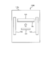
- an apparatus 100B as shown in FIG. 5 is usually used.
- the apparatus 100 ⁇ / b> B mainly includes an evaporating material 131, a high frequency coil 132, and a holder 133.
- the evaporation material 131 is, for example, a small piece of oxide, nitride, or nitride oxide such as aluminum (Al) or silicon (Si).
- the holder 133 holds the transparent fiber composite resin layer-containing multilayer raw sheet Sb.
- the high frequency coil 132 heats and evaporates the evaporation material 131.
- the transparent fiber composite resin layer-containing multilayer raw sheet Sb may be further provided with a layer other than the flattening resin layer 152.
- the transparent fiber composite resin layer-containing multilayer raw sheet Sb may be provided with other layers instead of the flattening resin layer 152.
- Example 1 ⁇ Example> Hereinafter, the present invention will be described in more detail with reference to Examples and Comparative Examples. The present invention is not limited to these examples.
- Example 1
- E-DOA Alicyclic epoxy resin having the following chemical formula (1)
- OX-SQH oxetanyl group-containing silxesquioxane
- SI-100L aromatic sulfonium thermal cationic curing agent
- a NE glass glass cloth (thickness 95 ⁇ m) was impregnated with the above resin composition to prepare a resin-impregnated glass cloth, and the resin-impregnated glass cloth was defoamed.
- the first direction is the MD direction (flow direction) and the second direction is the TD direction (vertical direction)
- the number of longitudinal glass yarns per inch width in the MD direction is 58.
- the number of transverse glass yarns per inch width in the TD direction is 50. That is, when the number of transverse glass yarns per inch width in the TD direction is 1, the ratio of the number of longitudinal glass yarns per inch width in the MD direction is 1.16.
- the cross-sectional area of the glass component in the glass yarn per inch width in the TD direction is 1, the ratio of the cross-sectional area of the glass component in the glass yarn per inch width in the MD direction is 1.35.
- the resin impregnated glass cloth is sandwiched between “two glass plates subjected to release treatment” and heated at 80 ° C. for 2 hours, and further heated at 250 ° C. for 2 hours to obtain a thickness of 97 ⁇ m.
- a transparent fiber composite resin sheet comprising the transparent fiber composite resin layer was obtained.
- the transparent fiber composite resin layer-containing multilayer raw sheet was placed in a chamber of an RF sputtering apparatus. After reducing the pressure in the chamber, Ar gas was introduced at 0.5 Pa and O 2 gas was introduced at a partial pressure of 0.005 Pa. Subsequently, an RF power of 0.3 kW was applied between the Si 3 N 4 target placed in the chamber and the transparent fiber composite resin layer for discharge. Meanwhile, the transparent fiber composite resin layer-containing multilayer raw sheet is heated to 200 ° C., and when the discharge is stabilized, the shutter provided between the target and the transparent fiber composite resin layer is opened, and SiO x N y is used. The film formation of the configured gas barrier layer was started. Thereafter, when the average thickness of the gas barrier layer reached 100 nm, the shutter was closed to complete the film formation. The chamber was opened to the atmosphere to obtain a transparent fiber composite resin layer-containing multilayer sheet.
- the optical anisotropy of the transparent fiber composite resin layer-containing multilayer sheet according to Example 1 was 3.3.
- the transparent fiber composite resin layer-containing multilayer sheet according to this example has a low haze value, low anisotropy of linear expansion coefficient, low water vapor transmission rate, and low optical anisotropy.
- the transparent fiber composite resin layer-containing multilayer sheet for optical devices was preferable.
- Example 1 except that instead of “heating the transparent fiber composite resin layer-containing multilayer original sheet to 200 ° C.”, “holding the transparent fiber composite resin layer-containing multilayer original sheet at 30 ° C.” Similarly, a transparent fiber composite resin layer-containing multilayer sheet was prepared, and each physical property was measured in the same manner as in Example 1.
- the haze is 1.9%
- the linear expansion coefficient in the MD direction is 12.2 ppm / K
- the linear expansion coefficient in the TD direction is 12.
- the water vapor permeability was 8 ppm / K
- the water vapor permeability was 0.02 g / m 2 / day / 40 degrees C, 90% RH
- the optical anisotropy was 3.5. That is, the transparent fiber composite resin layer-containing multilayer sheet according to Comparative Example 1 has a low haze value, low linear expansion coefficient anisotropy, and low optical anisotropy, but a high water vapor transmission value, It was not preferable for an optical device.
- Comparative Example 2 Comparative Example 2
- the glass cloth is “NE glass-based glass cloth in which the number of longitudinal glass yarns per inch width in the MD direction is 60 and the number of transverse glass yarns per inch width in the TD direction is 50”.
- transparent fiber composite resin layer-containing multilayer original sheet instead of “heating the transparent fiber composite resin layer-containing multilayer original sheet to 200 ° C.”, “transparent fiber composite resin layer-containing multilayer original sheet 30 ° C.
- a transparent fiber composite resin layer-containing multilayer sheet was prepared in the same manner as in Example 1 except that the method was changed to “holding”. The physical properties were measured in the same manner as in Example 1.
- the haze is 2.1%
- the linear expansion coefficient in the MD direction is 9.5 ppm / K
- the linear expansion coefficient in the TD direction is 12.
- the water vapor permeability was 0.02 g / m 2 / day / 40 degrees C, 90% RH
- the optical anisotropy was 4.9. That is, although the haze value is low, the values of the anisotropy of the linear expansion coefficient, the water vapor transmission rate, and the optical anisotropy are all high, which is not preferable for an optical device. (Comparative Example 3)
- Glass cloth is “NE glass-based glass cloth in which the number of longitudinal glass yarns per inch width in the MD direction is 50 and the number of transverse glass yarns per inch width in the TD direction is 50”.
- transparent fiber composite resin layer-containing multilayer original sheet instead of “heating the transparent fiber composite resin layer-containing multilayer original sheet to 200 ° C.”, “transparent fiber composite resin layer-containing multilayer original sheet 30 ° C.
- a transparent fiber composite resin layer-containing multilayer sheet was produced in the same manner as in Example 1 except that the content was changed to “holding”, and each physical property was measured in the same manner as in Example 1.
- the haze is 4.1%
- the linear expansion coefficient in the MD direction is 12.3 ppm / K
- the linear expansion coefficient in the TD direction is 13.
- the water vapor permeability was 0.02 g / m 2 / day / 40 ° C., 90% RH
- the optical anisotropy was 3.6. That is, although the anisotropy of the linear expansion coefficient is small and the optical anisotropy is low, the haze value and the water vapor transmission rate are high, which is not preferable for an optical device.
- the method for producing a transparent fiber composite resin layer-containing multilayer sheet according to the present invention can produce a transparent fiber composite resin layer-containing multilayer sheet that exhibits higher gas barrier properties than a conventional transparent fiber composite resin layer-containing multilayer sheet.
- transparent resin substrates that can be used for liquid crystal display elements, solar cells, electromagnetic wave shields, touch panels, organic EL substrates, color filters, and the like.
- Transparent fiber composite resin layer Transparent fiber composite resin sheet
- Transparent inorganic membrane Sa, Sa ′ Transparent fiber composite resin layer-containing multilayer sheet
- Sb Transparent fiber composite resin layer-containing multilayer raw sheet
- Raw fabric sheet Transparent fiber composite resin sheet
Landscapes
- Chemical & Material Sciences (AREA)
- Metallurgy (AREA)
- Chemical Kinetics & Catalysis (AREA)
- Engineering & Computer Science (AREA)
- Materials Engineering (AREA)
- Mechanical Engineering (AREA)
- Organic Chemistry (AREA)
- General Chemical & Material Sciences (AREA)
- Physics & Mathematics (AREA)
- Optics & Photonics (AREA)
- Laminated Bodies (AREA)
- Physical Vapour Deposition (AREA)
- Electroluminescent Light Sources (AREA)
Abstract
本発明により、透明繊維複合樹脂シート上に従前よりも緻密な無機質膜を形成し、ガスバリア性に優れる透明繊維複合樹脂層含有多層シートを製造することができる方法が提供される。本発明に係る透明繊維複合樹脂層含有多層シート製造方法では、透明繊維複合樹脂シート又は透明繊維複合樹脂層含有多層原反シートが加熱されながら透明繊維複合樹脂シートまたは透明繊維複合樹脂層含有多層原反シートの少なくとも片面上に透明無機質膜が形成される。なお、加熱は、透明繊維複合樹脂シート又は透明繊維複合樹脂層含有多層原反シートの温度が150度C以上「樹脂成分の劣化温度」以下の温度になるようになされるのが好ましい。
Description
本発明は、「繊維複合樹脂層を含有する多層シートの製造方法」および「同製造方法により得られる繊維複合樹脂層含有多層シートを基板として用いる光学装置」に関する。
本願は、2011年6月6日に日本に出願された特願2011-126055号に基づき優先権を主張し、その内容をここに援用する。
本願は、2011年6月6日に日本に出願された特願2011-126055号に基づき優先権を主張し、その内容をここに援用する。
過去に「スパッタリング法により高分子フィルム上に金属酸化物層を成膜して、透過率、水蒸気バリア性、酸素バリア性に優れる高透明ガスバリア性フィルムを製造する方法」が提案されている(例えば、特開2000-192237号公報参照)。また、上述の方法により得られる高透明ガスバリア性フィルムは、例えば、包装分野のみならず、液晶表示素子、太陽電池、電磁波シールド、タッチパネル、有機EL、カラーフィルター等のエレクトロニクス分野で、封止フィルムや基板としても利用されている。
ところで、近年、上述のようなエレクトロニクス製品用の透明樹脂シートとして、透明樹脂をガラス織布やガラス不織布等のガラス布帛に代表される繊維シートで補強したもの(以下、このような透明樹脂シートを「透明繊維複合樹脂シート」と称する)が広く知られている(例えば、特開2010-043199号公報、特開2007-224270号公報参照)。本発明の課題は、このような透明繊維複合樹脂シート上に、従前よりも緻密な無機質膜を形成し、ガスバリア性に優れる透明繊維複合樹脂層含有多層シートを製造することができる方法を提供することにある。
(1)
本発明に係る透明繊維複合樹脂層含有多層シート製造方法では、透明繊維複合樹脂シート又は透明繊維複合樹脂層含有多層原反シートが加熱されながら透明繊維複合樹脂シート又は透明繊維複合樹脂層含有多層原反シートの少なくとも片面上に透明無機質膜が形成される。ここで、「透明繊維複合樹脂シート」とは、透明な繊維複合樹脂層のみからなるシートを意味する。さらに、「透明繊維複合樹脂層含有多層原反シート」とは、透明な繊維複合樹脂層を含有する透明な多層原反シートを意味する。また、この透明繊維複合樹脂層含有多層シート製造方法において、透明繊維複合樹脂シート又は透明繊維複合樹脂層含有多層原反シートの温度が150度C以上「樹脂成分の劣化温度(分解温度、軟化温度、ガラス転移温度など)」以下の温度になるように加熱することが好ましい。樹脂を劣化させることなく緻密な透明無機質膜を形成することができるからである。また、透明無機質膜をさらに緻密化させるのに有利であるという観点から、加熱温度は180度C以上であることがより好ましく、200度C以上であることがさらに好ましい。
本発明に係る透明繊維複合樹脂層含有多層シート製造方法では、透明繊維複合樹脂シート又は透明繊維複合樹脂層含有多層原反シートが加熱されながら透明繊維複合樹脂シート又は透明繊維複合樹脂層含有多層原反シートの少なくとも片面上に透明無機質膜が形成される。ここで、「透明繊維複合樹脂シート」とは、透明な繊維複合樹脂層のみからなるシートを意味する。さらに、「透明繊維複合樹脂層含有多層原反シート」とは、透明な繊維複合樹脂層を含有する透明な多層原反シートを意味する。また、この透明繊維複合樹脂層含有多層シート製造方法において、透明繊維複合樹脂シート又は透明繊維複合樹脂層含有多層原反シートの温度が150度C以上「樹脂成分の劣化温度(分解温度、軟化温度、ガラス転移温度など)」以下の温度になるように加熱することが好ましい。樹脂を劣化させることなく緻密な透明無機質膜を形成することができるからである。また、透明無機質膜をさらに緻密化させるのに有利であるという観点から、加熱温度は180度C以上であることがより好ましく、200度C以上であることがさらに好ましい。
このため、この透明繊維複合樹脂層含有多層シート製造方法では、透明繊維複合樹脂シートまたは透明繊維複合樹脂層含有多層原反シートの少なくとも片面上に、従前の無機質膜よりも緻密な無機質膜が形成される。したがって、この透明繊維複合樹脂層含有多層シート製造方法により得られる透明繊維複合樹脂層含有多層シートは、従前の透明繊維複合樹脂層含有多層シートよりも高いガスバリア性を示すことができる。また、この透明繊維複合樹脂シート又は透明繊維複合樹脂層含有多層原反シートは、樹脂単体のフィルムに比べて線膨張係数(CTE)が十分に小さい。このため、この透明繊維複合樹脂層含有多層シート製造方法では、透明無機質膜に生じるクラックを低減することができる。
(2)
上述(1)の透明繊維複合樹脂層含有多層シート製造方法において、透明無機質膜は、スパッタリング、化学蒸着(CVD)又はイオンプレーティングにより形成されることが好ましい。
上述(1)の透明繊維複合樹脂層含有多層シート製造方法において、透明無機質膜は、スパッタリング、化学蒸着(CVD)又はイオンプレーティングにより形成されることが好ましい。
(3)
上述(1)または(2)の透明繊維複合樹脂層含有多層シート製造方法において、透明無機質膜は、アルミニウム(Al)原子およびシリコン(Si)原子から成る群から選択される少なくとも1種の原子を含有することが好ましい。
上述(1)または(2)の透明繊維複合樹脂層含有多層シート製造方法において、透明無機質膜は、アルミニウム(Al)原子およびシリコン(Si)原子から成る群から選択される少なくとも1種の原子を含有することが好ましい。
(4)
上述(1)から(3)の透明繊維複合樹脂層含有多層シート製造方法において、透明無機質膜は、アルミニウム(Al)原子およびシリコン(Si)原子から成る群から選択される少なくとも1種の原子を含有する酸化物、窒化物または酸化窒化物から形成されることが好ましい。
上述(1)から(3)の透明繊維複合樹脂層含有多層シート製造方法において、透明無機質膜は、アルミニウム(Al)原子およびシリコン(Si)原子から成る群から選択される少なくとも1種の原子を含有する酸化物、窒化物または酸化窒化物から形成されることが好ましい。
(5)
上述(1)から(4)の透明繊維複合樹脂層含有多層シート製造方法において、透明繊維複合樹脂シート又は透明繊維複合樹脂層含有多層原反シート中の繊維シートはガラス織布であることが好ましい。また、ガラス織布は複数の第1ガラス繊維束および複数の第2ガラス繊維束を備えることがより好ましい。なお、ここにいう「ガラス繊維束」とは、例えばガラスヤーンであり、第1ガラス繊維束は第1方向に配向する。第2ガラス繊維束は、平面視において第1方向と略直交する方向(以下「第2方向」と称する)に沿って第1ガラス繊維束に織り込まれている。そして、このガラス織布において、単位幅当たりの第2ガラス繊維束中のガラス成分の断面積に対する単位幅当たりの第1ガラス繊維束中のガラス成分の断面積の比は、1.04以上1.40以下であることがさらに好ましい。ここで、ガラス成分の断面積とは、ガラス繊維束(ガラスヤーン)を構成する各ガラスフィラメントの断面積の総和をいう。
上述(1)から(4)の透明繊維複合樹脂層含有多層シート製造方法において、透明繊維複合樹脂シート又は透明繊維複合樹脂層含有多層原反シート中の繊維シートはガラス織布であることが好ましい。また、ガラス織布は複数の第1ガラス繊維束および複数の第2ガラス繊維束を備えることがより好ましい。なお、ここにいう「ガラス繊維束」とは、例えばガラスヤーンであり、第1ガラス繊維束は第1方向に配向する。第2ガラス繊維束は、平面視において第1方向と略直交する方向(以下「第2方向」と称する)に沿って第1ガラス繊維束に織り込まれている。そして、このガラス織布において、単位幅当たりの第2ガラス繊維束中のガラス成分の断面積に対する単位幅当たりの第1ガラス繊維束中のガラス成分の断面積の比は、1.04以上1.40以下であることがさらに好ましい。ここで、ガラス成分の断面積とは、ガラス繊維束(ガラスヤーン)を構成する各ガラスフィラメントの断面積の総和をいう。
(6)
上述(5)の透明繊維複合樹脂層含有多層シート製造方法において、第1ガラス繊維束のガラス成分の断面積は、第2ガラス繊維束それぞれのガラス成分の断面積と実質的に等しいことが好ましい。また、かかる場合、単位幅当たりの第2ガラス繊維束の本数に対する単位幅当たりの第1ガラス繊維束の本数の比は、1.02以上1.18以下であることがより好ましい。
上述(5)の透明繊維複合樹脂層含有多層シート製造方法において、第1ガラス繊維束のガラス成分の断面積は、第2ガラス繊維束それぞれのガラス成分の断面積と実質的に等しいことが好ましい。また、かかる場合、単位幅当たりの第2ガラス繊維束の本数に対する単位幅当たりの第1ガラス繊維束の本数の比は、1.02以上1.18以下であることがより好ましい。
本発明に係る光学装置では、上述(1)から(6)のいずれかに係る透明繊維複合樹脂層含有多層シート製造方法により得られる透明繊維複合樹脂層含有多層シートが基板として用いられる。なお、ここにいう「光学装置」とは、例えば、液晶ディスプレイ・有機ELディスプレイ等の表示装置、有機EL照明等のディスプレイ照明装置等である。
本発明の実施の形態に係る透明繊維複合樹脂層含有多層シート製造方法では、透明繊維複合樹脂層含有多層原反シートSbが直接加熱された状態で、スパッタリング法により透明繊維複合樹脂層含有多層原反シートSb上に透明無機質膜153が形成され、透明繊維複合樹脂層含有多層シートSaが製造される(図2参照)。なお、以下、このような透明繊維複合樹脂層含有多層シート製造方法を実現するための具体的な装置について説明する。
<透明繊維複合樹脂層含有多層シート製造装置>
透明繊維複合樹脂層含有多層シート製造装置100は、図1に示されるように、主に、真空チャンバ110および透明繊維複合樹脂層含有多層シート製造部120から構成されている。以下、真空チャンバ110および透明繊維複合樹脂層含有多層シート製造部120について詳述する。
透明繊維複合樹脂層含有多層シート製造装置100は、図1に示されるように、主に、真空チャンバ110および透明繊維複合樹脂層含有多層シート製造部120から構成されている。以下、真空チャンバ110および透明繊維複合樹脂層含有多層シート製造部120について詳述する。
(1)真空チャンバ
真空チャンバ110は、気密性が非常に高いチャンバであって、内部に透明繊維複合樹脂層含有多層シート製造部120を包含する。なお、この真空チャンバ110は、一旦、十分な真空状態にされる。その後、この真空チャンバ110に必要量の不活性ガス(アルゴンや窒素等)が導入されてから(例えば、所定の圧力になるまで不活性ガスが導入されてから)、透明繊維複合樹脂層含有多層シートSa(図2参照)の製造が開始される。
真空チャンバ110は、気密性が非常に高いチャンバであって、内部に透明繊維複合樹脂層含有多層シート製造部120を包含する。なお、この真空チャンバ110は、一旦、十分な真空状態にされる。その後、この真空チャンバ110に必要量の不活性ガス(アルゴンや窒素等)が導入されてから(例えば、所定の圧力になるまで不活性ガスが導入されてから)、透明繊維複合樹脂層含有多層シートSa(図2参照)の製造が開始される。
(2)透明繊維複合樹脂層含有多層シート製造部
透明繊維複合樹脂層含有多層シート製造部120は、図1に示されるように、主に、繰出ロール121、メインロール129、第1サブロール122、第2サブロール123、巻取ロール124及びターゲット125から構成される。
透明繊維複合樹脂層含有多層シート製造部120は、図1に示されるように、主に、繰出ロール121、メインロール129、第1サブロール122、第2サブロール123、巻取ロール124及びターゲット125から構成される。
繰出ロール121は、透明繊維複合樹脂層含有多層原反シートSb(図2参照)を第1サブロール122に向かって繰り出す。なお、本実施の形態において、透明繊維複合樹脂層含有多層原反シートSbは、図2に示されるように、透明繊維複合樹脂層151および平坦化樹脂層152から構成されている。透明繊維複合樹脂層151は、ガラス布帛151aと、そのガラス布帛151aの屈折率と実質的に同一の屈折率を有する透明樹脂組成物151bとから形成されている。
第1サブロール122は、繰出ロール121から繰り出される透明繊維複合樹脂層含有多層原反シートSbをメインロール129に案内する。
メインロール129は、内部に加熱源(図示せず)を有しており、透明繊維複合樹脂層含有多層原反シートSbを加熱しながらターゲット125の対向位置まで送る。そして、ターゲット125近傍でスパッタリング処理された透明繊維複合樹脂層含有多層原反シートSbに透明無機質膜153(図2参照)が形成され、目的の透明繊維複合樹脂層含有多層シートSaが製造される。そして、その透明繊維複合樹脂層含有多層シートSaは、第2サブロール123に到達するまでメインロール129によって送られる。
なお、透明繊維複合樹脂層含有多層原反シートSbを加熱する方法としては、上述のメインロール129の内部に加熱源を設ける方法にかえて、メインロール129の表面近傍に外部ヒーター等を配置する方法等によってもよい。
第2サブロール123は、メインロール129から送られる透明繊維複合樹脂層含有多層シートSaを巻取ロール124に案内する。
巻取ロール124は、透明繊維複合樹脂層含有多層シートSaを巻き取る。
ターゲット125は、例えば、アルミニウム(Al)、シリコン(Si)等の酸化物、窒化物または窒化酸化物の小片である。高電圧によりイオン化された不活性ガスがこのターゲット125に衝突すると、このターゲット125の表面の原子が弾き飛ばされ、透明繊維複合樹脂層含有多層原反シートSb上に付着し、透明繊維複合樹脂層含有多層原反シートSb上に目的の透明無機質膜153が形成される。
なお、透明無機質膜153の形成には、上記のスパッタリング法に限られず、例えば反応性スパッタリング法、イオンプレーティング法または化学蒸着法(CVD)等が用いられてもよい。
<透明繊維複合樹脂層含有多層シートの詳細>
次に、透明繊維複合樹脂層含有多層シートSaは、図2に示されるように、透明繊維複合樹脂層151、平坦化樹脂層152および透明無機質膜153から構成されている。以下、透明繊維複合樹脂層151、平坦化樹脂層152および透明無機質膜153について詳述する。
次に、透明繊維複合樹脂層含有多層シートSaは、図2に示されるように、透明繊維複合樹脂層151、平坦化樹脂層152および透明無機質膜153から構成されている。以下、透明繊維複合樹脂層151、平坦化樹脂層152および透明無機質膜153について詳述する。
(1)透明繊維複合樹脂層
透明繊維複合樹脂層151は、上述の通り、ガラス布帛151aと、そのガラス布帛151aの屈折率と実質的に同一の屈折率を有する樹脂組成物151bとから形成されている。以下、ガラス布帛151aおよび樹脂組成物151bについて詳述する。
透明繊維複合樹脂層151は、上述の通り、ガラス布帛151aと、そのガラス布帛151aの屈折率と実質的に同一の屈折率を有する樹脂組成物151bとから形成されている。以下、ガラス布帛151aおよび樹脂組成物151bについて詳述する。
(A)ガラス布帛
ガラス布帛151aとしては、例えば、ガラス織布、ガラス不織布が例示される。ガラス布帛151aがガラス織布である場合、ガラス織布の織り組織としては、平織り、ななこ織り、朱子織り、綾織り等が挙げられる。ガラス布帛を構成するガラス繊維の素材としては、Eガラス、Cガラス、Aガラス、Sガラス、Dガラス、Tガラス、NEガラス、石英ガラス、低誘導率ガラス、高誘導率ガラス等が挙げられる。
ガラス布帛151aとしては、例えば、ガラス織布、ガラス不織布が例示される。ガラス布帛151aがガラス織布である場合、ガラス織布の織り組織としては、平織り、ななこ織り、朱子織り、綾織り等が挙げられる。ガラス布帛を構成するガラス繊維の素材としては、Eガラス、Cガラス、Aガラス、Sガラス、Dガラス、Tガラス、NEガラス、石英ガラス、低誘導率ガラス、高誘導率ガラス等が挙げられる。
(a)
ガラス布帛151aとしてガラス織布を用いる場合、ガラス織布は複数の第1ガラス繊維束および複数の第2ガラス繊維束を備えることが好ましい。なお、ここにいう「ガラス繊維束」とは、ガラスヤーンである。第1ガラス繊維束は、第1方向に配向する。第2ガラス繊維束は、平面視において第1方向と略直交する方向(以下「第2方向」と称する)に沿って第1ガラス繊維束に織り込まれている。さらに、このガラス織布において、単位幅当たりの第2ガラス繊維束中のガラス成分の断面積に対する単位幅当たりの第1ガラス繊維束中のガラス成分の断面積の比は、1.04以上1.40以下であることがより好ましい。ここで、ガラス成分の断面積とは、ガラス繊維束(ガラスヤーン)を構成する各ガラスフィラメントの断面積の総和をいう。
ガラス布帛151aとしてガラス織布を用いる場合、ガラス織布は複数の第1ガラス繊維束および複数の第2ガラス繊維束を備えることが好ましい。なお、ここにいう「ガラス繊維束」とは、ガラスヤーンである。第1ガラス繊維束は、第1方向に配向する。第2ガラス繊維束は、平面視において第1方向と略直交する方向(以下「第2方向」と称する)に沿って第1ガラス繊維束に織り込まれている。さらに、このガラス織布において、単位幅当たりの第2ガラス繊維束中のガラス成分の断面積に対する単位幅当たりの第1ガラス繊維束中のガラス成分の断面積の比は、1.04以上1.40以下であることがより好ましい。ここで、ガラス成分の断面積とは、ガラス繊維束(ガラスヤーン)を構成する各ガラスフィラメントの断面積の総和をいう。
さらにこのガラス織布において、単位幅当たりの第2ガラス繊維束中のガラス成分の断面積に対する単位幅当たりの第1ガラス繊維束中のガラス成分の断面積の比は、1.04以上1.40以下であることが好ましい。このため、このガラス織布は、透明繊維複合樹脂層含有多層シートに加工された場合に、縦方向と横方向とにおける線膨張係数の差を十分に小さくすることができる。
したがって、このガラス織布は、透明繊維複合樹脂層含有多層シートに加工された場合に、透明繊維複合樹脂層含有多層シートのヘイズ値を低減することができると共に、透明繊維複合樹脂層含有多層シートの縦方向と横方向とにおける線膨張係数の差を十分に小さくすることができる。線膨張係数の差を小さくすることにより、バリアを積層する際の歪み差が低減することができ、これにより歪み差による光学異方性を低減することが出来る。よって、このガラス織布は、透明繊維複合樹脂層含有多層シートに対して、「さらなる透明性」、「縦方向および横方向の線膨張係数の均等性」および「歪み差由来の光学異方性の低減」を付与することができる。
(b)
さらに、上述の(a)に係るガラス織布において、第1ガラス繊維束それぞれのガラス成分の断面積は、第2ガラス繊維束それぞれのガラス成分の断面積と実質的に等しいことが好ましい。また、かかる場合、単位幅当たりの第2ガラス繊維束の本数に対する単位幅当たりの第1ガラス繊維束の本数の比は、1.02以上1.18以下であることが好ましい。
さらに、上述の(a)に係るガラス織布において、第1ガラス繊維束それぞれのガラス成分の断面積は、第2ガラス繊維束それぞれのガラス成分の断面積と実質的に等しいことが好ましい。また、かかる場合、単位幅当たりの第2ガラス繊維束の本数に対する単位幅当たりの第1ガラス繊維束の本数の比は、1.02以上1.18以下であることが好ましい。
上記によれば、このガラス織布は、同じ太さのガラス繊維束だけで、上述の(a)に係るガラス織布と同様の効果を得ることができる。このため、ガラス織布、延いては透明ガラス繊維複合樹脂シートの製造コストを低く維持することができる。
なお、上記に記載されるような透明ガラス繊維複合樹脂シートを得るためには、上記に記載されるガラス繊維またはガラス繊維束の断面積比または本数比がガラス織布全体の80%以上の領域において成立すればよい。
(B)樹脂組成物
樹脂組成物151bとしては、例えば、エポキシ系樹脂、アクリル系樹脂、フェノール樹脂、シアネート樹脂およびそのブレンド樹脂が挙げられる。エポキシ系樹脂としては、例えば、脂環式エポキシ樹脂が挙げられる。また、アクリル系樹脂としては、例えば、熱硬化性または光硬化性のアクリル系樹脂などが挙げられる。
樹脂組成物151bとしては、例えば、エポキシ系樹脂、アクリル系樹脂、フェノール樹脂、シアネート樹脂およびそのブレンド樹脂が挙げられる。エポキシ系樹脂としては、例えば、脂環式エポキシ樹脂が挙げられる。また、アクリル系樹脂としては、例えば、熱硬化性または光硬化性のアクリル系樹脂などが挙げられる。
樹脂組成物151bとして、エポキシ樹脂を使用する場合、透明性、耐熱性を両立するという観点から、脂環構造を有する下記一般式(A)で表わされる脂環式エポキシ樹脂を使用することが好ましい。

(上記式中、-X-は、-O-、-S-、-SO-、-SO2-、-CH2-、-CH(CH3)-、-C(CH3)2-または単結合である。)
(上記式中、-X-は、-O-、-S-、-SO-、-SO2-、-CH2-、-CH(CH3)-、-C(CH3)2-または単結合である。)
(2)平坦化樹脂層
平坦化樹脂層152は、透明繊維複合樹脂層151の表面を平坦化する層であって、透明な樹脂から構成されている。なお、この平坦化樹脂層152を構成する透明な樹脂は、上述の透明樹脂組成物151bと同一の透明樹脂組成物から形成されてもよいし、他の透明樹脂組成物から形成されてもよい。
透明繊維複合樹脂層151の表面に平滑化樹脂層152が形成されていると、表面をより平滑にすることが可能となり、後述する透明無機質膜の欠陥低減などの効果があり、より高いガスバリア性を確保することが可能となる。
平坦化樹脂層152は、透明繊維複合樹脂層151の表面を平坦化する層であって、透明な樹脂から構成されている。なお、この平坦化樹脂層152を構成する透明な樹脂は、上述の透明樹脂組成物151bと同一の透明樹脂組成物から形成されてもよいし、他の透明樹脂組成物から形成されてもよい。
透明繊維複合樹脂層151の表面に平滑化樹脂層152が形成されていると、表面をより平滑にすることが可能となり、後述する透明無機質膜の欠陥低減などの効果があり、より高いガスバリア性を確保することが可能となる。
(3)透明無機質膜
透明無機質膜153は、アルミニウム(Al)、シリコン(Si)等の酸化物、窒化物または窒化酸化物から形成されている。
透明無機質膜153は、アルミニウム(Al)、シリコン(Si)等の酸化物、窒化物または窒化酸化物から形成されている。
<透明繊維複合樹脂層含有多層シート製造方法の特徴>
本発明の実施の形態に係る透明繊維複合樹脂層含有多層シート製造方法では、透明繊維複合樹脂層含有多層原反シートSbがメインロール129により加熱されながら、透明繊維複合樹脂層含有多層原反シートSb上に透明無機質膜153が形成される。ここで、本願発明に係る透明繊維複合樹脂層含有多層シートはガラス布帛を使用しているため、樹脂のみのシートと比べて耐熱性に優れる。よって、ガラス布帛を用いないで透明樹脂シートを製造する際よりも高い温度で透明無機質膜を形成することができるので、従来よりも緻密な無機層を形成することができる。さらに、ガラス布帛自体が無機質であるため、無機層形成時における接着性が良いことが期待できる。このため、この透明繊維複合樹脂層含有多層シート製造方法では、透明繊維複合樹脂層含有多層原反シートSb上に、従前の透明無機質膜よりも緻密な透明無機質膜153が形成される。したがって、この透明繊維複合樹脂層含有多層シート製造方法により得られる透明繊維複合樹脂層含有多層シートSaは、樹脂単体のシートや無機層形成時に加熱を行わない透明繊維複合樹脂層含有多層シートよりも高いガスバリア性を示すことができる。
本発明の実施の形態に係る透明繊維複合樹脂層含有多層シート製造方法では、透明繊維複合樹脂層含有多層原反シートSbがメインロール129により加熱されながら、透明繊維複合樹脂層含有多層原反シートSb上に透明無機質膜153が形成される。ここで、本願発明に係る透明繊維複合樹脂層含有多層シートはガラス布帛を使用しているため、樹脂のみのシートと比べて耐熱性に優れる。よって、ガラス布帛を用いないで透明樹脂シートを製造する際よりも高い温度で透明無機質膜を形成することができるので、従来よりも緻密な無機層を形成することができる。さらに、ガラス布帛自体が無機質であるため、無機層形成時における接着性が良いことが期待できる。このため、この透明繊維複合樹脂層含有多層シート製造方法では、透明繊維複合樹脂層含有多層原反シートSb上に、従前の透明無機質膜よりも緻密な透明無機質膜153が形成される。したがって、この透明繊維複合樹脂層含有多層シート製造方法により得られる透明繊維複合樹脂層含有多層シートSaは、樹脂単体のシートや無機層形成時に加熱を行わない透明繊維複合樹脂層含有多層シートよりも高いガスバリア性を示すことができる。
<変形例>
(A)
先の実施の形態では透明繊維複合樹脂層含有多層原反シートSbとして平坦化樹脂層152を備えたものが使用されたが、原反シートSb’として透明繊維複合樹脂層151のみから成る透明繊維複合樹脂シート(図3参照)が使用されてもよい。なお、かかる場合、透明繊維複合樹脂層含有多層シートSa’は、図3に示されるように、透明繊維複合樹脂層151および透明無機質膜153から構成されることになる。
(A)
先の実施の形態では透明繊維複合樹脂層含有多層原反シートSbとして平坦化樹脂層152を備えたものが使用されたが、原反シートSb’として透明繊維複合樹脂層151のみから成る透明繊維複合樹脂シート(図3参照)が使用されてもよい。なお、かかる場合、透明繊維複合樹脂層含有多層シートSa’は、図3に示されるように、透明繊維複合樹脂層151および透明無機質膜153から構成されることになる。
(B)
先の実施の形態では図1に示される透明繊維複合樹脂層含有多層シート製造装置100により透明繊維複合樹脂層含有多層シートSaが製造されたが、透明繊維複合樹脂層含有多層シートSaは、図4に示される透明繊維複合樹脂層含有多層シート製造装置100Aによっても製造することができる。なお、透明繊維複合樹脂層含有多層シート製造装置100Aは、隔壁126、予備加熱装置127およびクライオポンプ128が設置されている以外、先の実施の形態に係る透明繊維複合樹脂層含有多層シート製造装置100と同じである。したがって、透明繊維複合樹脂層含有多層シート製造装置100の構成要素と同一の構成要素については、同一の符号を付することによって説明を省略する。
先の実施の形態では図1に示される透明繊維複合樹脂層含有多層シート製造装置100により透明繊維複合樹脂層含有多層シートSaが製造されたが、透明繊維複合樹脂層含有多層シートSaは、図4に示される透明繊維複合樹脂層含有多層シート製造装置100Aによっても製造することができる。なお、透明繊維複合樹脂層含有多層シート製造装置100Aは、隔壁126、予備加熱装置127およびクライオポンプ128が設置されている以外、先の実施の形態に係る透明繊維複合樹脂層含有多層シート製造装置100と同じである。したがって、透明繊維複合樹脂層含有多層シート製造装置100の構成要素と同一の構成要素については、同一の符号を付することによって説明を省略する。
隔壁126は、ターゲット125、および、ターゲット125に対向するメインロール129の一部を他の空間SP2から隔離する。つまり、この隔壁126は、スパッタリング領域SP1を他の空間SP2から隔離しているとも言える。
隔壁126によりスパッタリング領域SP1を他の空間SP2から隔離することで、ターゲット125から放出された原子・分子がSP1から拡散することを防止し、他の空間を汚染することを防止できる。
隔壁126によりスパッタリング領域SP1を他の空間SP2から隔離することで、ターゲット125から放出された原子・分子がSP1から拡散することを防止し、他の空間を汚染することを防止できる。
予備加熱装置127は、繰出ロール121と第1サブロール122との間に配置されており、繰出ロール121から繰り出される透明繊維複合樹脂層含有多層原反シートSbを加熱して、透明繊維複合樹脂層含有多層原反シートSbから水分を排出させる。
透明繊維複合樹脂層含有多層原反シートSbから水分を排出させることにより、その後に積層される透明無機質膜が水分による影響を受けることがなくなるため、ガスバリア性が高く高品質な透明無機質膜を形成することが可能となる。
透明繊維複合樹脂層含有多層原反シートSbから水分を排出させることにより、その後に積層される透明無機質膜が水分による影響を受けることがなくなるため、ガスバリア性が高く高品質な透明無機質膜を形成することが可能となる。
クライオポンプ128は、ため込み式真空ポンプであって、予備加熱装置127により透明繊維複合樹脂層含有多層原反シートSbから排出される水分を凝縮させて捕捉する。なお、このクライオポンプ128は、図4に示されるように、主に、熱交換器128a、チラーユニット128b、冷媒供給配管128cおよび冷媒戻り配管128dから構成されている。なお、上述の水分は、熱交換器128aにより凝縮されて捕捉される。
(C)
先の実施の形態に係る透明繊維複合樹脂層含有多層シート製造方法では透明無機質膜153の形成にスパッタリング法が用いられたが、透明無機質膜153の形成には、イオンプレーティング法または化学蒸着法(CVD)等が用いられてもよい。
先の実施の形態に係る透明繊維複合樹脂層含有多層シート製造方法では透明無機質膜153の形成にスパッタリング法が用いられたが、透明無機質膜153の形成には、イオンプレーティング法または化学蒸着法(CVD)等が用いられてもよい。
イオンプレーティング法では、通常、図5に示されるような装置100Bが用いられる。この装置100Bは、図5に示されるように、主に、蒸発材料131、高周波コイル132およびホルダー133から構成される。
蒸発材料131は、例えば、アルミニウム(Al)、シリコン(Si)等の酸化物、窒化物または窒化酸化物の小片である。
ホルダー133には、透明繊維複合樹脂層含有多層原反シートSbが保持される。
高周波コイル132は、蒸発材料131を加熱し、蒸発させる。
(D)
先の実施の形態では特に言及しなかったが、透明繊維複合樹脂層含有多層原反シートSbには、平坦化樹脂層152以外の層がさらに設けられていてもかまわない。また、透明繊維複合樹脂層含有多層原反シートSbには、平坦化樹脂層152に代えて他の層が設けられていてもかまわない。
先の実施の形態では特に言及しなかったが、透明繊維複合樹脂層含有多層原反シートSbには、平坦化樹脂層152以外の層がさらに設けられていてもかまわない。また、透明繊維複合樹脂層含有多層原反シートSbには、平坦化樹脂層152に代えて他の層が設けられていてもかまわない。
<実施例>
以下、実施例および比較例を示して本発明をより詳細に説明する。なお、本発明は、これらの実施例に限定されることはない。
(実施例1)
以下、実施例および比較例を示して本発明をより詳細に説明する。なお、本発明は、これらの実施例に限定されることはない。
(実施例1)
1.透明繊維複合樹脂層含有多層シートの作製
(1)透明繊維複合樹脂層含有多層原反シートの作製
下記化学式(1)を有する脂環式エポキシ樹脂E-DOA(以下、「E-DOA」と略する,ダイセル化学工業株式会社製,硬化(架橋)後の屈折率1.513)90重量部と、オキセタニル基含有シルキセスキオキサン(以下「OX-SQH」と略する,東亜合成株式会社,硬化(架橋)後の屈折率1.47)10重量部との混合物、芳香族スルホニウム系熱カチオン硬化剤SI-100L(以下「SI-100L」と略する,三新化学工業株式会社製)1重量部とを混合して、樹脂組成物を調製した。

(1)透明繊維複合樹脂層含有多層原反シートの作製
下記化学式(1)を有する脂環式エポキシ樹脂E-DOA(以下、「E-DOA」と略する,ダイセル化学工業株式会社製,硬化(架橋)後の屈折率1.513)90重量部と、オキセタニル基含有シルキセスキオキサン(以下「OX-SQH」と略する,東亜合成株式会社,硬化(架橋)後の屈折率1.47)10重量部との混合物、芳香族スルホニウム系熱カチオン硬化剤SI-100L(以下「SI-100L」と略する,三新化学工業株式会社製)1重量部とを混合して、樹脂組成物を調製した。
次いで、上述の樹脂組成物をNEガラス系ガラスクロス(厚さ95μm)に含浸させて樹脂含浸ガラスクロスを調製した後、その樹脂含浸ガラスクロスに対して脱泡処理を行った。ここで、このガラスクロスにおいては、第1方向をMD方向(流れ方向)、第2方向をTD方向(垂直方向)とした場合、MD方向の1インチ幅当たりの縦方向ガラスヤーンの本数が58本であり、TD方向の1インチ幅当たりの横方向ガラスヤーンの本数は50本である。すなわち、TD方向の1インチ幅当たりの横方向ガラスヤーンの本数を1としたとき、MD方向の1インチ幅当たりの縦方向ガラスヤーンの本数の比は1.16である。
また、このガラスクロスは、TD方向の1インチ幅当たりのガラスヤーン中のガラス成分の断面積を1としたとき、MD方向の1インチ幅当たりのガラスヤーン中のガラス成分の断面積の比は1.35である。そして、この樹脂含浸ガラスクロスを「離型処理された2枚のガラス板」に挟み込んだ状態で、80度Cで2時間加熱した後、さらに250度Cで2時間加熱して、厚さ97μmの透明繊維複合樹脂層からなる透明繊維複合樹脂シートを得た。
(2)平滑層の成膜
脂環式エポキシ樹脂(E-DOA)100質量部と、光カチオン重合開始剤(株式会社ADEKA製、SP-170)1質量部と、を混合し、被覆材料を調製した。次いで、バーコーターにより透明繊維複合樹脂層の両面に塗布した後、高圧水銀灯にて1100mJ/cm2の紫外線を照射した。さらに、250度Cで2時間加熱することにより平均厚さ5μmの平滑層(平坦化樹脂層)を成膜し、透明繊維複合樹脂層含有多層原反シートを得た。
脂環式エポキシ樹脂(E-DOA)100質量部と、光カチオン重合開始剤(株式会社ADEKA製、SP-170)1質量部と、を混合し、被覆材料を調製した。次いで、バーコーターにより透明繊維複合樹脂層の両面に塗布した後、高圧水銀灯にて1100mJ/cm2の紫外線を照射した。さらに、250度Cで2時間加熱することにより平均厚さ5μmの平滑層(平坦化樹脂層)を成膜し、透明繊維複合樹脂層含有多層原反シートを得た。
(3)ガスバリア層の成膜
次いで、透明繊維複合樹脂層含有多層原反シートをRFスパッタリング装置のチャンバ内に載置した。そして、チャンバ内を減圧した後、Arガスを0.5Pa、O2ガスを0.005Paの分圧で導入した。続いて、チャンバ内に載置されたSi3N4ターゲットと透明繊維複合樹脂層との間に0.3kWのRF電力を印加して放電させた。その一方で、透明繊維複合樹脂層含有多層原反シートを200度Cに加熱し、放電が安定したところでターゲットと透明繊維複合樹脂層との間に設けていたシャッターを開き、SiOxNyで構成されたガスバリア層の成膜を開始した。その後、ガスバリア層の平均厚さが100nmになったところでシャッターを閉じ、成膜を終了した。そして、チャンバを大気開放して、透明繊維複合樹脂層含有多層シートを得た。
次いで、透明繊維複合樹脂層含有多層原反シートをRFスパッタリング装置のチャンバ内に載置した。そして、チャンバ内を減圧した後、Arガスを0.5Pa、O2ガスを0.005Paの分圧で導入した。続いて、チャンバ内に載置されたSi3N4ターゲットと透明繊維複合樹脂層との間に0.3kWのRF電力を印加して放電させた。その一方で、透明繊維複合樹脂層含有多層原反シートを200度Cに加熱し、放電が安定したところでターゲットと透明繊維複合樹脂層との間に設けていたシャッターを開き、SiOxNyで構成されたガスバリア層の成膜を開始した。その後、ガスバリア層の平均厚さが100nmになったところでシャッターを閉じ、成膜を終了した。そして、チャンバを大気開放して、透明繊維複合樹脂層含有多層シートを得た。
2.各種物性の測定
(1)ヘイズの測定
JIS K7136の規定に従い、日本電色工業株式会社製のNDH2000を用いてヘイズを測定した。この結果、本実施例1に係る透明繊維複合樹脂層含有多層シートのヘイズは1.8%であった。
(1)ヘイズの測定
JIS K7136の規定に従い、日本電色工業株式会社製のNDH2000を用いてヘイズを測定した。この結果、本実施例1に係る透明繊維複合樹脂層含有多層シートのヘイズは1.8%であった。
(2)線膨張係数の測定
透明繊維複合樹脂層含有多層シートから試験片を切り出し、その試験片を熱応力歪測定装置(セイコー電子株式会社製TMA/SS120C型)にセットした。その後、窒素雰囲気下において、無荷重の試験片を雰囲気温度30度Cから150度Cまで5度C/分の昇温速度で上昇させた後、一旦0度Cまで冷却した。さらに、試験片を5gの荷重で引っ張りながら、雰囲気温度を30度Cから150度Cまで5度C/分の昇温速度で上昇させ、MD方向、TD方向の線膨張係数の測定を行った。この結果、本実施例1に係る透明繊維複合樹脂層含有多層シートのMD方向の線膨張率は12.1ppm/K、TD方向の線膨張率が12.8ppm/Kであった。
透明繊維複合樹脂層含有多層シートから試験片を切り出し、その試験片を熱応力歪測定装置(セイコー電子株式会社製TMA/SS120C型)にセットした。その後、窒素雰囲気下において、無荷重の試験片を雰囲気温度30度Cから150度Cまで5度C/分の昇温速度で上昇させた後、一旦0度Cまで冷却した。さらに、試験片を5gの荷重で引っ張りながら、雰囲気温度を30度Cから150度Cまで5度C/分の昇温速度で上昇させ、MD方向、TD方向の線膨張係数の測定を行った。この結果、本実施例1に係る透明繊維複合樹脂層含有多層シートのMD方向の線膨張率は12.1ppm/K、TD方向の線膨張率が12.8ppm/Kであった。
(3)ガスバリア性の評価
JIS K 7129 Bの規定に従い、水蒸気透過度を測定した(表1参照)。この結果、本実施例1に係る透明繊維複合樹脂層含有多層シートのMD方向の水蒸気透過度は測定限界値(0.01)以下であった。
JIS K 7129 Bの規定に従い、水蒸気透過度を測定した(表1参照)。この結果、本実施例1に係る透明繊維複合樹脂層含有多層シートのMD方向の水蒸気透過度は測定限界値(0.01)以下であった。
(4)光学異方性の評価
透明繊維複合樹脂層含有多層シートをクロスニコルにした偏光顕微鏡で観察した。次いで、偏光顕微鏡の光軸を固定し、光源の強さを一定にした状態で透明繊維複合樹脂層含有多層シートを回転させ、基板の一部分あるいは全体が最も明るくなる角度にセットした。そして、2.4mm×1.8mmの観察部分を画像(画素数640×480)化してパーソナルコンピューターに取り込み、取り込んだ画像を各画素が0~255の階調を持つ白黒画像に変換した。得られた白黒画像中の各画素の階調を総和し、これを光学異方性の評価値とした。この結果、本実施例1に係る透明繊維複合樹脂層含有多層シートの光学異方性は3.3であった。
透明繊維複合樹脂層含有多層シートをクロスニコルにした偏光顕微鏡で観察した。次いで、偏光顕微鏡の光軸を固定し、光源の強さを一定にした状態で透明繊維複合樹脂層含有多層シートを回転させ、基板の一部分あるいは全体が最も明るくなる角度にセットした。そして、2.4mm×1.8mmの観察部分を画像(画素数640×480)化してパーソナルコンピューターに取り込み、取り込んだ画像を各画素が0~255の階調を持つ白黒画像に変換した。得られた白黒画像中の各画素の階調を総和し、これを光学異方性の評価値とした。この結果、本実施例1に係る透明繊維複合樹脂層含有多層シートの光学異方性は3.3であった。
3.総評
以上より、本実施例に係る透明繊維複合樹脂層含有多層シートはヘイズ値が低く、線膨張率の異方性が少なく、水蒸気透過率が低く、さらには光学異方性が低いものであり、光学装置用の透明繊維複合樹脂層含有多層シートとして好ましいものであった。
(比較例1)
以上より、本実施例に係る透明繊維複合樹脂層含有多層シートはヘイズ値が低く、線膨張率の異方性が少なく、水蒸気透過率が低く、さらには光学異方性が低いものであり、光学装置用の透明繊維複合樹脂層含有多層シートとして好ましいものであった。
(比較例1)
「透明繊維複合樹脂層含有多層原反シートを200度Cに加熱」したことに代えて、「透明繊維複合樹脂層含有多層原反シートを30度Cに保持」した以外は、実施例1と同様にして透明繊維複合樹脂層含有多層シートを作製し、実施例1と同様にして各物性を測定した。
表1に示すとおり、比較例1に係る透明繊維複合樹脂層含有多層シートでは、ヘイズが1.9%、MD方向の線膨張率が12.2ppm/K、TD方向の線膨張率が12.8ppm/K、水蒸気透過度が0.02g/m2/day/40度C、90%RH、光学異方性が3.5であった。すなわち、本比較例1に係る透明繊維複合樹脂層含有多層シートは、ヘイズ値が低く、線膨張率の異方性が少なく、光学異方性が低いものの、水蒸気透過率の値が高いため、光学装置用として好ましいものではなかった。
(比較例2)
(比較例2)
ガラスクロスを、「MD方向の1インチ幅当たりの縦方向ガラスヤーンの本数が60本であり、TD方向の1インチ幅当たりの横方向ガラスヤーンの本数は50本であるNEガラス系ガラスクロス」へ替えたこと、ガスバリア層の成膜において「透明繊維複合樹脂層含有多層原反シートを200度Cに加熱」することに替えて、「透明繊維複合樹脂層含有多層原反シートを30度Cに保持」することに替えたこと以外は、実施例1と同様にして透明繊維複合樹脂層含有多層シートを作製し、実施例1と同様にして各物性を測定した。
表1に示すとおり、比較例2に係る透明繊維複合樹脂層含有多層シートでは、ヘイズが2.1%、MD方向の線膨張率が9.5ppm/K、TD方向の線膨張率が12.6ppm/K、水蒸気透過度が0.02g/m2/day/40度C、90%RH、光学異方性が4.9であった。すまわち、ヘイズ値は低いものの、線膨張率の異方性、水蒸気透過率、および光学異方性のいずれの値も高いため、光学装置用として好ましいものではなかった。
(比較例3)
(比較例3)
ガラスクロスを、「MD方向の1インチ幅当たりの縦方向ガラスヤーンの本数が50本であり、TD方向の1インチ幅当たりの横方向ガラスヤーンの本数は50本であるNEガラス系ガラスクロス」に替えたこと、ガスバリア層の成膜において「透明繊維複合樹脂層含有多層原反シートを200度Cに加熱」することに替えて、「透明繊維複合樹脂層含有多層原反シートを30度Cに保持」することに変更した以外は、実施例1と同様にして透明繊維複合樹脂層含有多層シートを作製し、実施例1と同様にして各物性を測定した。
表1に示すとおり、比較例3に係る透明繊維複合樹脂層含有多層シートでは、ヘイズが4.1%、MD方向の線膨張率が12.3ppm/K、TD方向の線膨張率が13.1ppm/K、水蒸気透過度が0.02g/m2/day/40度C、90%RH、光学異方性が3.6であった。すなわち、線膨張率の異方性が少なく、光学異方性が低いものの、ヘイズ値および水蒸気透過率が高く、光学装置用として好ましいものではなかった。
本発明に係る透明繊維複合樹脂層含有多層シート製造方法は、従前の透明繊維複合樹脂層含有多層シートよりも高いガスバリア性を示す透明繊維複合樹脂層含有多層シートを製造することができるという特徴を有しており、例えば、液晶表示素子、太陽電池、電磁波シールド、タッチパネル、有機EL基板、カラーフィルター等に利用可能な透明樹脂基板の製造に有用である。
151 透明繊維複合樹脂層(透明繊維複合樹脂シート)
153 透明無機質膜
Sa,Sa’ 透明繊維複合樹脂層含有多層シートSb 透明繊維複合樹脂層含有多層原反シート
Sb’ 原反シート(透明繊維複合樹脂シート)
153 透明無機質膜
Sa,Sa’ 透明繊維複合樹脂層含有多層シートSb 透明繊維複合樹脂層含有多層原反シート
Sb’ 原反シート(透明繊維複合樹脂シート)

Claims (9)
- 透明繊維複合樹脂シート又は透明繊維複合樹脂層含有多層原反シートを加熱しながら前記透明繊維複合樹脂シートまたは前記透明繊維複合樹脂層含有多層原反シートの少なくとも片面上に透明無機質膜を形成する
透明繊維複合樹脂層含有多層シート製造方法。 - 前記透明無機質膜は、スパッタリングにより形成される
請求項1に記載の透明繊維複合樹脂層含有多層シート製造方法。 - 前記透明無機質膜は、化学蒸着(CVD)又はイオンプレーティングにより形成される
請求項1に記載の透明繊維複合樹脂層含有多層シート製造方法。 - 前記透明無機質膜は、アルミニウム(Al)原子およびシリコン(Si)原子から成る群から選択される少なくとも1種の原子を含有する
請求項1から3のいずれかに記載の透明繊維複合樹脂層含有多層シート製造方法。 - 前記透明無機質膜は、アルミニウム(Al)原子およびシリコン(Si)原子から成る群から選択される少なくとも1種の原子を含有する酸化物、窒化物または酸化窒化物から形成される
請求項4に記載の透明繊維複合樹脂層含有多層シート製造方法。 - 前記透明繊維複合樹脂シート又は前記透明繊維複合樹脂層含有多層原反シート中の繊維シートはガラス織布である
請求項1から3のいずれかに記載の透明繊維複合樹脂層含有多層シート製造方法。 - 前記ガラス織布は、第1方向に配向する複数の第1ガラス繊維束と、
平面視において前記第1方向と略直交する方向に沿って前記第1ガラス繊維束に織り込まれる複数の第2ガラス繊維束と
を備え、
単位幅当たりの前記第2ガラス繊維束中のガラス成分の断面積に対する前記単位幅当たりの前記第1ガラス繊維束中のガラス成分の断面積の比は、1.04以上1.40以下である
請求項6に記載の透明繊維複合樹脂層含有多層シート製造方法。 - 前記第1ガラス繊維束におけるガラス成分の断面積は、前記第2ガラス繊維束におけるガラス成分の断面積と実質的に等しく、
前記単位幅当たりの前記第2ガラス繊維束の本数に対する前記単位幅当たりの前記第1ガラス繊維束の本数の比が、1.02以上1.18以下である
請求項7に記載の透明繊維複合樹脂層含有多層シート製造方法。 - 請求項1から3のいずれかに記載の透明繊維複合樹脂層含有多層シート製造方法により得られる透明繊維複合樹脂層含有多層シートが基板として用いられる光学装置。
Priority Applications (2)
| Application Number | Priority Date | Filing Date | Title |
|---|---|---|---|
| CN201280022447.8A CN103547445A (zh) | 2011-06-06 | 2012-06-05 | 含有纤维复合树脂层的多层片的制造方法和光学装置 |
| KR1020137029407A KR101645072B1 (ko) | 2011-06-06 | 2012-06-05 | 섬유 복합 수지층 함유 다층 시트 제조 방법 및 광학 장치 |
Applications Claiming Priority (2)
| Application Number | Priority Date | Filing Date | Title |
|---|---|---|---|
| JP2011-126055 | 2011-06-06 | ||
| JP2011126055 | 2011-06-06 |
Publications (1)
| Publication Number | Publication Date |
|---|---|
| WO2012169500A1 true WO2012169500A1 (ja) | 2012-12-13 |
Family
ID=47296062
Family Applications (1)
| Application Number | Title | Priority Date | Filing Date |
|---|---|---|---|
| PCT/JP2012/064484 Ceased WO2012169500A1 (ja) | 2011-06-06 | 2012-06-05 | 繊維複合樹脂層含有多層シート製造方法および光学装置 |
Country Status (5)
| Country | Link |
|---|---|
| JP (1) | JP2013014131A (ja) |
| KR (1) | KR101645072B1 (ja) |
| CN (1) | CN103547445A (ja) |
| TW (1) | TW201305258A (ja) |
| WO (1) | WO2012169500A1 (ja) |
Citations (3)
| Publication number | Priority date | Publication date | Assignee | Title |
|---|---|---|---|---|
| JP2004233851A (ja) * | 2003-01-31 | 2004-08-19 | Asahi Kasei Electronics Co Ltd | 透明基板 |
| JP2007051214A (ja) * | 2005-08-18 | 2007-03-01 | Fujifilm Corp | 複合材料、ならびにそれを用いたフィルムおよび画像表示装置 |
| JP2010043199A (ja) * | 2008-08-13 | 2010-02-25 | Asahi Kasei E-Materials Corp | 透明基板及びその製造方法 |
Family Cites Families (10)
| Publication number | Priority date | Publication date | Assignee | Title |
|---|---|---|---|---|
| JP2000192237A (ja) | 1998-12-25 | 2000-07-11 | Teijin Ltd | 高透明ガスバリア性フィルムの製造方法 |
| JP2004346386A (ja) * | 2003-05-23 | 2004-12-09 | Toppan Printing Co Ltd | 真空成膜装置及び透明ガスバリアフィルム |
| JP4269261B2 (ja) * | 2003-07-18 | 2009-05-27 | 住友ベークライト株式会社 | 透明ガスバリアフィルムの製造方法 |
| US20080000388A1 (en) * | 2004-10-22 | 2008-01-03 | Yoshiyuki Abe | Gas Barrier Transparent Resin Substrate Method for Manufacturing Thereof, and Flexible Display Element Using Barrier Transparent Resin Substrate |
| JP4569336B2 (ja) * | 2005-03-22 | 2010-10-27 | 住友ベークライト株式会社 | 透明バリア性シート |
| CN101049746A (zh) * | 2006-01-26 | 2007-10-10 | Jsr株式会社 | 透明复合体及其制造方法 |
| JP2007224270A (ja) | 2006-01-26 | 2007-09-06 | Jsr Corp | 透明複合体およびその製造方法 |
| JP2008180754A (ja) * | 2007-01-23 | 2008-08-07 | Mitsubishi Plastics Ind Ltd | 光学シート、及び該光学シートの製造方法 |
| KR101145247B1 (ko) * | 2009-06-08 | 2012-05-24 | 이문승 | 유리섬유직물을 이용하여 강도를 향상시킨 합성수지관의 제조장치와 이를 이용하여 제조된 합성수지관 |
| JP2011218586A (ja) * | 2010-04-06 | 2011-11-04 | Gunze Ltd | 透明ガスバリアフィルム |
-
2012
- 2012-05-30 JP JP2012123484A patent/JP2013014131A/ja active Pending
- 2012-06-05 KR KR1020137029407A patent/KR101645072B1/ko not_active Expired - Fee Related
- 2012-06-05 WO PCT/JP2012/064484 patent/WO2012169500A1/ja not_active Ceased
- 2012-06-05 CN CN201280022447.8A patent/CN103547445A/zh active Pending
- 2012-06-05 TW TW101120172A patent/TW201305258A/zh unknown
Patent Citations (3)
| Publication number | Priority date | Publication date | Assignee | Title |
|---|---|---|---|---|
| JP2004233851A (ja) * | 2003-01-31 | 2004-08-19 | Asahi Kasei Electronics Co Ltd | 透明基板 |
| JP2007051214A (ja) * | 2005-08-18 | 2007-03-01 | Fujifilm Corp | 複合材料、ならびにそれを用いたフィルムおよび画像表示装置 |
| JP2010043199A (ja) * | 2008-08-13 | 2010-02-25 | Asahi Kasei E-Materials Corp | 透明基板及びその製造方法 |
Also Published As
| Publication number | Publication date |
|---|---|
| CN103547445A (zh) | 2014-01-29 |
| TW201305258A (zh) | 2013-02-01 |
| KR20130136000A (ko) | 2013-12-11 |
| JP2013014131A (ja) | 2013-01-24 |
| KR101645072B1 (ko) | 2016-08-02 |
Similar Documents
| Publication | Publication Date | Title |
|---|---|---|
| US8415003B2 (en) | Flexible substrate for display panel and manufacturing method thereof | |
| TWI516552B (zh) | 偏光板及包含其之影像顯示裝置 | |
| EP2680048A1 (en) | Fine structure form and liquid-crystal display device comprising fine structure form | |
| US20100134879A1 (en) | Display screen protection film and polarization plate | |
| US6793981B2 (en) | Process for producing laminated film, and reflection reducing film | |
| JP2012509213A (ja) | 多層プラスチック基板及びその製造方法 | |
| CN105531620A (zh) | 光学膜、阻隔膜、光转换部件、背光单元及液晶显示装置 | |
| WO2005051654A1 (ja) | 樹脂シート、液晶セル基板、液晶表示装置、エレクトロルミネッセンス表示装置用基板、エレクトロルミネッセンス表示装置および太陽電池用基板 | |
| CN1871533A (zh) | 叠层膜 | |
| JPWO2011033751A1 (ja) | 透明熱可塑性ポリイミド、およびそれを含む透明基板 | |
| KR20140066772A (ko) | 투명 복합 기판 및 표시 소자 기판 | |
| JP5196705B2 (ja) | 光学シート | |
| CN101743267B (zh) | 多层膜及其制造方法 | |
| TW201514333A (zh) | 防濕性基材之製造方法及防濕性基材、以及使用防濕性基材之偏光板、液晶顯示面板 | |
| JP2011500915A (ja) | 複合材料、これにより製造された複合フィルムおよび複合フィルムの製造方法 | |
| JP4393077B2 (ja) | 透明基板 | |
| US20140273686A1 (en) | Transparent composite substrate and display element substrate | |
| JP2007203473A (ja) | 複合シート | |
| JP4424044B2 (ja) | 透明複合シート及びそれを用いた表示素子 | |
| JP2008049695A (ja) | 透明積層体 | |
| KR101645072B1 (ko) | 섬유 복합 수지층 함유 다층 시트 제조 방법 및 광학 장치 | |
| JP2004307811A (ja) | 表示素子用プラスチック基板 | |
| JP6434366B2 (ja) | 透明導電性積層体 | |
| TWI913380B (zh) | 積層體及附有相位差層之偏光板之製造方法 | |
| US20150190992A1 (en) | Transparent composite material and method and apparatus for manufacturing the same |
Legal Events
| Date | Code | Title | Description |
|---|---|---|---|
| 121 | Ep: the epo has been informed by wipo that ep was designated in this application |
Ref document number: 12796734 Country of ref document: EP Kind code of ref document: A1 |
|
| ENP | Entry into the national phase |
Ref document number: 20137029407 Country of ref document: KR Kind code of ref document: A |
|
| NENP | Non-entry into the national phase |
Ref country code: DE |
|
| 122 | Ep: pct application non-entry in european phase |
Ref document number: 12796734 Country of ref document: EP Kind code of ref document: A1 |