WO2012161355A1 - 希土類焼結磁石、希土類焼結磁石の製造方法及び回転機 - Google Patents
希土類焼結磁石、希土類焼結磁石の製造方法及び回転機 Download PDFInfo
- Publication number
- WO2012161355A1 WO2012161355A1 PCT/JP2012/064254 JP2012064254W WO2012161355A1 WO 2012161355 A1 WO2012161355 A1 WO 2012161355A1 JP 2012064254 W JP2012064254 W JP 2012064254W WO 2012161355 A1 WO2012161355 A1 WO 2012161355A1
- Authority
- WO
- WIPO (PCT)
- Prior art keywords
- rare earth
- concentration region
- sintered magnet
- main phase
- earth sintered
- Prior art date
- Legal status (The legal status is an assumption and is not a legal conclusion. Google has not performed a legal analysis and makes no representation as to the accuracy of the status listed.)
- Ceased
Links
Images









Classifications
-
- C—CHEMISTRY; METALLURGY
- C22—METALLURGY; FERROUS OR NON-FERROUS ALLOYS; TREATMENT OF ALLOYS OR NON-FERROUS METALS
- C22C—ALLOYS
- C22C33/00—Making ferrous alloys
- C22C33/02—Making ferrous alloys by powder metallurgy
-
- C—CHEMISTRY; METALLURGY
- C22—METALLURGY; FERROUS OR NON-FERROUS ALLOYS; TREATMENT OF ALLOYS OR NON-FERROUS METALS
- C22C—ALLOYS
- C22C38/00—Ferrous alloys, e.g. steel alloys
- C22C38/002—Ferrous alloys, e.g. steel alloys containing In, Mg, or other elements not provided for in one single group C22C38/001 - C22C38/60
-
- C—CHEMISTRY; METALLURGY
- C22—METALLURGY; FERROUS OR NON-FERROUS ALLOYS; TREATMENT OF ALLOYS OR NON-FERROUS METALS
- C22C—ALLOYS
- C22C38/00—Ferrous alloys, e.g. steel alloys
- C22C38/005—Ferrous alloys, e.g. steel alloys containing rare earths, i.e. Sc, Y, Lanthanides
-
- C—CHEMISTRY; METALLURGY
- C22—METALLURGY; FERROUS OR NON-FERROUS ALLOYS; TREATMENT OF ALLOYS OR NON-FERROUS METALS
- C22C—ALLOYS
- C22C38/00—Ferrous alloys, e.g. steel alloys
- C22C38/06—Ferrous alloys, e.g. steel alloys containing aluminium
-
- C—CHEMISTRY; METALLURGY
- C22—METALLURGY; FERROUS OR NON-FERROUS ALLOYS; TREATMENT OF ALLOYS OR NON-FERROUS METALS
- C22C—ALLOYS
- C22C38/00—Ferrous alloys, e.g. steel alloys
- C22C38/10—Ferrous alloys, e.g. steel alloys containing cobalt
-
- C—CHEMISTRY; METALLURGY
- C22—METALLURGY; FERROUS OR NON-FERROUS ALLOYS; TREATMENT OF ALLOYS OR NON-FERROUS METALS
- C22C—ALLOYS
- C22C38/00—Ferrous alloys, e.g. steel alloys
- C22C38/14—Ferrous alloys, e.g. steel alloys containing titanium or zirconium
-
- C—CHEMISTRY; METALLURGY
- C22—METALLURGY; FERROUS OR NON-FERROUS ALLOYS; TREATMENT OF ALLOYS OR NON-FERROUS METALS
- C22C—ALLOYS
- C22C38/00—Ferrous alloys, e.g. steel alloys
- C22C38/16—Ferrous alloys, e.g. steel alloys containing copper
-
- H—ELECTRICITY
- H01—ELECTRIC ELEMENTS
- H01F—MAGNETS; INDUCTANCES; TRANSFORMERS; SELECTION OF MATERIALS FOR THEIR MAGNETIC PROPERTIES
- H01F1/00—Magnets or magnetic bodies characterised by the magnetic materials therefor; Selection of materials for their magnetic properties
- H01F1/01—Magnets or magnetic bodies characterised by the magnetic materials therefor; Selection of materials for their magnetic properties of inorganic materials
- H01F1/03—Magnets or magnetic bodies characterised by the magnetic materials therefor; Selection of materials for their magnetic properties of inorganic materials characterised by their coercivity
- H01F1/032—Magnets or magnetic bodies characterised by the magnetic materials therefor; Selection of materials for their magnetic properties of inorganic materials characterised by their coercivity of hard-magnetic materials
- H01F1/04—Magnets or magnetic bodies characterised by the magnetic materials therefor; Selection of materials for their magnetic properties of inorganic materials characterised by their coercivity of hard-magnetic materials metals or alloys
- H01F1/047—Alloys characterised by their composition
- H01F1/053—Alloys characterised by their composition containing rare earth metals
- H01F1/055—Alloys characterised by their composition containing rare earth metals and magnetic transition metals, e.g. SmCo5
- H01F1/057—Alloys characterised by their composition containing rare earth metals and magnetic transition metals, e.g. SmCo5 and IIIa elements, e.g. Nd2Fe14B
- H01F1/0571—Alloys characterised by their composition containing rare earth metals and magnetic transition metals, e.g. SmCo5 and IIIa elements, e.g. Nd2Fe14B in the form of particles, e.g. rapid quenched powders or ribbon flakes
- H01F1/0575—Alloys characterised by their composition containing rare earth metals and magnetic transition metals, e.g. SmCo5 and IIIa elements, e.g. Nd2Fe14B in the form of particles, e.g. rapid quenched powders or ribbon flakes pressed, sintered or bonded together
- H01F1/0577—Alloys characterised by their composition containing rare earth metals and magnetic transition metals, e.g. SmCo5 and IIIa elements, e.g. Nd2Fe14B in the form of particles, e.g. rapid quenched powders or ribbon flakes pressed, sintered or bonded together sintered
-
- H—ELECTRICITY
- H01—ELECTRIC ELEMENTS
- H01F—MAGNETS; INDUCTANCES; TRANSFORMERS; SELECTION OF MATERIALS FOR THEIR MAGNETIC PROPERTIES
- H01F1/00—Magnets or magnetic bodies characterised by the magnetic materials therefor; Selection of materials for their magnetic properties
- H01F1/01—Magnets or magnetic bodies characterised by the magnetic materials therefor; Selection of materials for their magnetic properties of inorganic materials
- H01F1/03—Magnets or magnetic bodies characterised by the magnetic materials therefor; Selection of materials for their magnetic properties of inorganic materials characterised by their coercivity
- H01F1/032—Magnets or magnetic bodies characterised by the magnetic materials therefor; Selection of materials for their magnetic properties of inorganic materials characterised by their coercivity of hard-magnetic materials
- H01F1/04—Magnets or magnetic bodies characterised by the magnetic materials therefor; Selection of materials for their magnetic properties of inorganic materials characterised by their coercivity of hard-magnetic materials metals or alloys
- H01F1/06—Magnets or magnetic bodies characterised by the magnetic materials therefor; Selection of materials for their magnetic properties of inorganic materials characterised by their coercivity of hard-magnetic materials metals or alloys in the form of particles, e.g. powder
- H01F1/08—Magnets or magnetic bodies characterised by the magnetic materials therefor; Selection of materials for their magnetic properties of inorganic materials characterised by their coercivity of hard-magnetic materials metals or alloys in the form of particles, e.g. powder pressed, sintered, or bound together
- H01F1/086—Magnets or magnetic bodies characterised by the magnetic materials therefor; Selection of materials for their magnetic properties of inorganic materials characterised by their coercivity of hard-magnetic materials metals or alloys in the form of particles, e.g. powder pressed, sintered, or bound together sintered
-
- H—ELECTRICITY
- H01—ELECTRIC ELEMENTS
- H01F—MAGNETS; INDUCTANCES; TRANSFORMERS; SELECTION OF MATERIALS FOR THEIR MAGNETIC PROPERTIES
- H01F41/00—Apparatus or processes specially adapted for manufacturing or assembling magnets, inductances or transformers; Apparatus or processes specially adapted for manufacturing materials characterised by their magnetic properties
- H01F41/02—Apparatus or processes specially adapted for manufacturing or assembling magnets, inductances or transformers; Apparatus or processes specially adapted for manufacturing materials characterised by their magnetic properties for manufacturing cores, coils, or magnets
- H01F41/0253—Apparatus or processes specially adapted for manufacturing or assembling magnets, inductances or transformers; Apparatus or processes specially adapted for manufacturing materials characterised by their magnetic properties for manufacturing cores, coils, or magnets for manufacturing permanent magnets
- H01F41/0266—Moulding; Pressing
-
- B—PERFORMING OPERATIONS; TRANSPORTING
- B22—CASTING; POWDER METALLURGY
- B22F—WORKING METALLIC POWDER; MANUFACTURE OF ARTICLES FROM METALLIC POWDER; MAKING METALLIC POWDER; APPARATUS OR DEVICES SPECIALLY ADAPTED FOR METALLIC POWDER
- B22F2998/00—Supplementary information concerning processes or compositions relating to powder metallurgy
- B22F2998/10—Processes characterised by the sequence of their steps
-
- C—CHEMISTRY; METALLURGY
- C22—METALLURGY; FERROUS OR NON-FERROUS ALLOYS; TREATMENT OF ALLOYS OR NON-FERROUS METALS
- C22C—ALLOYS
- C22C2202/00—Physical properties
- C22C2202/02—Magnetic
Definitions
- the present invention relates to a rare earth sintered magnet used for a magnetic field generator such as a rotating machine such as a motor or a magnetic resonance imaging system (MRI), a method for manufacturing the rare earth sintered magnet, and a rotating machine.
- a magnetic field generator such as a rotating machine such as a motor or a magnetic resonance imaging system (MRI)
- MRI magnetic resonance imaging system
- R-T-B As a rare earth sintered magnet, R-T-B (R represents one or more rare earth elements containing one or both of Nd and Pr as main components, and T represents one or more kinds including Fe or Fe and Co.
- RTB based rare earth sintered magnets having a composition of a transition element (B represents B or B and C) are known.
- the RTB-based rare earth sintered magnet has a structure including a main phase composed of an R 2 T 14 B compound and a grain boundary phase including an R-rich phase containing more R than the main phase.
- the RTB-based rare earth sintered magnet is a magnet that exhibits excellent magnetic properties such as having a high coercive force HcJ.
- R-T-B rare earth sintered magnets are high performance permanent magnets, such as electric cars, hybrid cars, hard disk drive (HDD) voice coil motors (VCM), MRI's.
- HDD hard disk drive
- VCM voice coil motors
- MRI magnetic resonance imaging
- Such a magnetic field generator is widely used in motors, generators, and the like that require high performance, and is particularly used in applications that require high magnetic properties.
- R-T-B rare earth sintered magnets have a high activity because they contain R in their composition. For example, since they are easily oxidized by oxygen in the atmosphere, the corrosion resistance as an element body is not high, and the magnetic properties are likely to deteriorate due to oxidation. .
- the R-T-B rare earth sintered magnet when used in various devices such as a motor, the R-T-B rare earth sintered magnet has a good coercive force HcJ in order to cope with use in a high temperature environment. Is required to maintain temperature characteristics.
- R-T-B rare earth sintered magnet when surface treatment is performed on an R-T-B rare earth sintered magnet, chamfering is generally performed with a barrel or the like as a pretreatment. For this reason, if the strength of the R-T-B rare earth sintered magnet is low, cracking and chipping including chipping occur due to processing, resulting in poor yield. Furthermore, as products using R-T-B rare earth sintered magnets are diversified, thinner and smaller products are required. Such thinner and smaller products are more susceptible to cracking and chipping. Therefore, in order to improve the yield in manufacturing such a product, an RTB-based rare earth sintered magnet with higher mechanical strength is required.
- the magnetic properties of the rare earth sintered magnet cannot be improved sufficiently stably only by the presence of a plurality of regions having a high concentration of Dy in the main phase particles.
- RTB-based rare earth sintered magnets tend to be used in a wider range of applications such as automobiles and industrial equipment. Applications are increasing. For this reason, it is required to improve the temperature characteristics of the RTB-based rare earth sintered magnet so that the coercive force HcJ can be maintained high even in a high temperature environment. In addition, it is required to improve the strength of the R-T-B rare earth sintered magnet and improve the corrosion resistance.
- the present invention has been made in view of the above, and it is an object of the present invention to provide a rare earth sintered magnet, a rare earth sintered magnet manufacturing method, and a rotating machine that improve temperature characteristics and strength and have excellent corrosion resistance.
- the present inventors have intensively studied rare earth sintered magnets.
- the concentration of the heavy rare earth element varies depending on the concentration of the heavy rare earth element (including at least one of or both of Dy and Tb) in a part of the main phase particles included in the rare earth sintered magnet.
- the three regions are a low concentration region, a high concentration region, and a medium concentration region. These three regions are included in the main phase so as to form a three-layer structure in the order of the low concentration region, the high concentration region, and the medium concentration region from the low concentration region to the grain boundary phase.
- the rare earth sintered magnet according to the present invention is R 2 T 14 B (R is one or more rare earth elements containing one or both of Nd and Pr as main components, and T Is a rare earth sintered magnet including at least a main phase composed of a compound (which represents Fe or one or more transition elements including Fe and Co) and a grain boundary phase containing more R than the main phase, , Containing a heavy rare earth element (including at least one of or both of Dy and Tb), and at least a part of main phase particles of the main phase contained in the rare earth sintered magnet has a concentration of the heavy rare earth element.
- the three regions having different heavy rare earth element concentrations include a low concentration region having the lowest concentration of the heavy rare earth elements and a region having the three heavy rare earth element concentrations. Most in A high concentration region, a medium concentration region in which the concentration of the heavy rare earth element is higher than the low concentration region and lower than the high concentration region, and the three regions are the low concentration region in the main phase particle.
- the low-concentration region, the high-concentration region, and the medium-concentration region exist in this order from the grain boundary phase toward the grain boundary phase.
- the main phase particles include at least three regions according to the concentration of heavy rare earth element, the movement of the domain wall of the reverse domain is suppressed by the difference in concentration of heavy rare earth element. Therefore, when the main phase is formed only in a uniform high concentration region over the entire region of the main phase, or a main phase including a region having a higher rare earth concentration than the low concentration region is formed outside the low concentration region.
- the coercive force HcJ can be maintained high even in a high temperature environment as compared to the case where the That is, it is considered that the temperature characteristics of the obtained rare earth sintered magnet can be improved.
- heavy rare earth elements tend to oxidize compared to light rare earth elements such as Nd.
- some main phase particles include three regions according to the concentration of heavy rare earth elements, A medium concentration region is formed in a region close to the grain boundary phase. Therefore, compared to the case where the main phase is formed only in the high concentration region in the entire main phase region or the case where the main phase including the high concentration region is formed outside the low concentration region, the corrosion resistance of the rare earth sintered magnet Can be improved.
- the interface state between the main phase and the grain boundary phase increases the overall strength of the rare earth sintered magnet. It has an influence.
- some of the main phase particles include at least three regions depending on the concentration of the heavy rare earth element.
- the main phase includes three regions in the order of a low concentration region, a high concentration region, and a medium concentration region from the low concentration region toward the grain boundary phase. That is, it is considered that the interface state between the main phase and the grain boundary phase is improved, and the strength of the rare earth sintered magnet can be increased.
- At least a part of the main phase particles of the main phase contained in the rare earth sintered magnet includes three regions having different concentrations of heavy rare earth elements. Are a low concentration region, a high concentration region, and a medium concentration region. The three regions exist in the order of a low concentration region, a high concentration region, and a medium concentration region from the low concentration region in the main phase toward the grain boundary phase. For this reason, it is possible to improve temperature characteristics and strength and to have excellent corrosion resistance.
- the rare earth sintered magnet according to the present invention is formed with the main phase formed only in the high concentration region in the entire main phase region or the main phase formed including the high concentration region outside the low concentration region.
- Rare earth sintered magnets having the same coercive force HcJ can be produced using a small amount of heavy rare earth elements as compared with conventional magnets. For this reason, the cost required to produce the rare earth sintered magnet obtained can be reduced.
- main phase particles in which the high concentration region is adjacent to at least a part of the low concentration region and the medium concentration region is adjacent to at least a part of the high concentration region are the rare earth elements. It is preferable that 5% or more is present in the sintered magnet. By including a predetermined amount of main phase particles, the characteristics of the obtained rare earth sintered magnet can be stably obtained.
- the main phase particles are present in the rare earth sintered magnet by 30% or more.
- the rare earth sintered magnet is obtained because the three regions have more main phase particles in which the high concentration region is adjacent to at least a part of the low concentration region and the medium concentration region is adjacent to at least a part of the high concentration region. The characteristics can be further stably improved.
- the rare earth sintered It is preferable that 3% or more is present in the magnet.
- the three regions are included in the main phase particles in a state in which the low concentration region, the high concentration region, and the medium concentration region are formed circumferentially from the low concentration region toward the grain boundary phase.
- the main phase particles are preferably present in the rare earth sintered magnet in an amount of 5% or more.
- the number of main phase particles existing in a three-layer structure in which the three regions are in the order of the low concentration region, the high concentration region, and the medium concentration region further increases, so that the characteristics of the obtained rare earth sintered magnet are further stably improved. be able to.
- the average value of the concentration of the heavy rare earth element in the medium concentration region is the average value of the concentration of the heavy rare earth element from the maximum concentration of the heavy rare earth element to the grain boundary phase. Therefore, the average value of the concentration of heavy rare earth elements in the medium concentration region formed in the grain boundary phase from the high concentration region becomes clear.
- the minimum concentration of the heavy rare earth element in the main phase is ⁇
- the maximum concentration of the heavy rare earth element in the main phase is ⁇
- the concentration of the heavy rare earth element in the medium concentration region is represented by the following formula (A), and the value of the following formula (A) is 0.2 or more and 0.8 or less. It is preferable to be within the range.
- the average concentration of heavy rare earth elements in the medium concentration region formed from the maximum concentration to the grain boundary phase is within a predetermined range, thereby making the three-layer structure of the low concentration region, the high concentration region, and the medium concentration region clearer. It becomes. Thereby, the excellent corrosion resistance can be obtained more stably while improving the temperature characteristics and strength of the obtained rare earth sintered magnet.
- the value of the formula (A) is in the range of 0.3 to 0.75.
- the average concentration of heavy rare earth elements in the medium concentration region formed from the high concentration region to the grain boundary phase is within a predetermined range, thereby further clarifying the three-layer structure of the low concentration region, the high concentration region, and the medium concentration region.
- the characteristics of the obtained rare earth sintered magnet can be obtained more stably.
- the value of the mathematical formula (A) is preferably in the range of 0.35 to 0.7.
- the main phase alloy containing the R 2 T 14 B compound, HR (HR represents one or more rare earth elements containing at least one of Dy and Tb, or both) and T at least It is preferable to use the intergranular phase-based alloy as a raw material alloy. Thereby, a rare earth sintered magnet can be manufactured stably.
- the relative density of the rare earth sintered magnet is preferably 99% or more. Accordingly, a three-layer structure of a low concentration region, a high concentration region, and a medium concentration region is formed in order from the low concentration region in the main phase particle toward the grain boundary phase according to the concentration of the heavy rare earth element.
- a rare earth sintered magnet including a large amount of main phase particles including at least three regions can be stably formed.
- the method of manufacturing a rare earth sintered magnet according to the present invention includes R 2 T 14 B (R is one or more rare earths containing one or both of Nd and Pr as main components).
- R is one or more rare earths containing one or both of Nd and Pr as main components.
- it includes at least an alloy powder of a main phase alloy containing an R 2 T 14 B compound, HR (HR represents one or more rare earth elements including at least one of Dy and Tb) and T.
- An alloy powder of a grain boundary phase alloy is mixed to obtain a mixture, a forming step of forming the mixture to obtain a formed body, and an average temperature rise rate of 600 ° C. or higher up to the sintering temperature is 2 ° C. / Min or more 10 ° C /
- a temperature increasing step of raising the temperature of the molded body as in or below a sintering step of sintering the molded body to obtain a sintered body, and an average cooling rate from the sintering temperature to 600 ° C.
- At least a part of the main phase particles of the main phase included in the structure includes at least three regions having different concentrations of the heavy rare earth element, and the three regions having different concentrations of the heavy rare earth element include the heavy rare earth element.
- At least three regions having different heavy rare earth element concentrations can be formed in the main phase of the sintered magnet.
- the three regions are a low concentration region, a high concentration region, and a medium concentration region. These three regions can be included in the order of a low concentration region, a high concentration region, and a medium concentration region in accordance with the concentration of heavy rare earth elements from the low concentration region toward the grain boundary phase.
- a rare earth sintered magnet with improved magnetic properties can be efficiently produced with a smaller amount of heavy rare earth elements.
- the movement of the domain wall of the reverse magnetic domain is suppressed by the concentration difference of the heavy rare earth element. Therefore, when the main phase is formed only in a uniform high concentration region over the entire region of the main phase, or a main phase including a region having a higher rare earth concentration than the low concentration region is formed outside the low concentration region.
- the coercive force HcJ can be maintained high even in a high temperature environment as compared to the case where the For this reason, it is considered that the temperature characteristics of the obtained rare earth sintered magnet can be further improved.
- a medium concentration region is formed in a region close to the grain boundary phase in the main phase particles. Therefore, compared to the case where the main phase is formed only in the high concentration region in the entire main phase region or the case where the main phase including the high concentration region is formed outside the low concentration region, the concentration of the heavy rare earth element is lower. Since it is relatively low, it is considered that the corrosion resistance can be improved.
- the main phase includes a three-layer structure including a low concentration region, a high concentration region, and a medium concentration region in this order from the low concentration region toward the grain boundary phase, depending on the concentration of the heavy rare earth element. This is considered to improve the interface state between the main phase and the grain boundary phase and increase the strength of the rare earth sintered magnet.
- Heavy rare earth elements have a coercive force equivalent to that of the main phase formed only in the high concentration region in the entire main phase region and the main phase formed including the high concentration region outside the low concentration region.
- the rare earth sintered magnet having HcJ can be produced using a small amount of heavy rare earth elements, and the cost required for producing the rare earth sintered magnet can be reduced.
- At least a part of the main phase particles of the main phase contained in the rare earth sintered magnet has a low concentration region according to the concentration of the heavy rare earth element from the low concentration region toward the grain boundary phase, A three-layer structure is included in the order of a high concentration region and a medium concentration region. For this reason, a heavy rare earth element can be efficiently distributed in the main phase, temperature characteristics and strength can be improved, and a rare earth sintered magnet having excellent corrosion resistance can be obtained.
- a rotating machine includes any one of the rare earth sintered magnets described above.
- the rare earth sintered magnet according to the present invention as a permanent magnet used in a rotating machine such as a motor or a magnetic field generator such as MRI, a high coercive force HcJ can be obtained even in a high temperature use environment.
- the permanent magnet is made thinner and smaller, it can have high strength. For this reason, performance, such as a rotating machine and a magnetic field generator, can be improved further.
- FIG. 1 is a schematic diagram schematically showing the structure of the main phase contained in the rare earth sintered magnet.
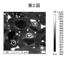
- FIG. 2 is an SEM composition image of a rare earth sintered magnet.
- FIG. 3 is a diagram schematically showing the boundary of the main phase.
- FIG. 4 is an observation result of the Dy concentration of the rare earth sintered magnet by EPMA.
- FIG. 5 is an observation result of the Nd concentration of the rare earth sintered magnet by PMA.
- FIG. 6 is an observation result of the Fe concentration of the rare earth sintered magnet by EPMA.
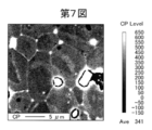
- FIG. 7 is a diagram showing an example of a composition image of a rare earth sintered magnet.
- FIG. 8 is a diagram showing an observation result of EPy of Dy in the composition image in FIG. FIG.
- FIG. 9 is a diagram showing the result of the detected intensity of Dy when the EPMA in FIG. 8 is subjected to line analysis.
- FIG. 10 is an explanatory diagram illustrating an example of a line analysis result.
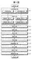
- FIG. 11 is a flowchart showing an example of a method for producing a rare earth sintered magnet according to an embodiment of the present invention.
- FIG. 12 is a cross-sectional view schematically showing the configuration of an embodiment of an SPM motor.
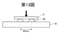
- FIG. 13 is an explanatory view schematically showing an example of a three-point bending strength test.
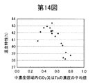
- FIG. 14 is a diagram showing the relationship between the Dy concentration in the medium concentration region and the temperature characteristic (ratio of coercivity at 140 ° C. and room temperature).
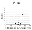
- FIG. 15 is a diagram showing the relationship between the Dy concentration in the medium concentration region and the corrosion resistance of the same sample as in FIG.
- FIG. 16 is a diagram showing the relationship between the Dy concentration and the intensity in the medium concentration region of the same sample as in FIG.
- FIG. 17 is a diagram showing the relationship between the Dy concentration in the medium concentration region and the temperature characteristic (ratio of coercive force at 200 ° C. and room temperature).
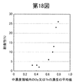
- FIG. 18 is a diagram showing the relationship between the Dy concentration in the medium concentration region and the corrosion resistance of the same sample as in FIG.
- FIG. 19 is a diagram showing the relationship between the Dy concentration and the intensity in the medium concentration region of the same sample as in FIG.
- the rare earth sintered magnet according to the present embodiment is R 2 T 14 B (R is one or more rare earth elements containing one or both of Nd and Pr as main components, and T is Fe or Fe and Co. At least a main phase composed of a compound (representing one or more transition elements) and a grain boundary phase containing more R than the main phase.
- This rare earth sintered magnet is a sintered body produced using an RTB-based alloy.
- the rare earth sintered magnet includes both magnet products obtained by processing the magnet and magnets that are not magnetized.
- the main phase has a crystal structure made of R 2 T 14 B type tetragonal crystal.
- the particle size of the main phase is usually about 1 ⁇ m to 30 ⁇ m.
- the grain boundary phase includes an R-rich phase containing more R than the main phase.
- the grain boundary phase may include a boron-rich phase containing more boron (B) than the main phase.
- R represents one or more rare earth elements containing one or both of Nd and Pr as main components.
- Rare earth elements refer to Sc, Y, and lanthanoid elements belonging to Group 3 of the long-period periodic table. Examples of the lanthanoid element include La, Ce, Pr, Nd, Sm, Eu, Gd, Tb, Dy, Ho, Er, Tm, Yb, Lu, and the like. Rare earth elements are classified into light rare earths and heavy rare earths.
- the heavy rare earth element HR refers to Gd, Tb, Dy, Ho, Er, Tm, Yb, and Lu. Light rare earth elements are other rare earth elements. From the viewpoint of manufacturing cost and magnetic properties, R preferably contains one or both of Nd and Pr as a main component.
- T represents one or more transition elements including Fe or Fe and Co.
- T may be Fe alone or a part of Fe may be substituted with Co.
- T for example, Al, Ga, Si, Ti, Bi, Sb, Ge, Sn, Zn, from the viewpoint of improving the coercive force HcJ and reducing manufacturing costs. It may further contain at least one element such as V, Cr, Mn, Ni, Cu, Zr, Nb, Mo, Hf, Ta, and W.
- B may be B alone, or a part of B may be substituted with C. Since C has corrosion resistance, the corrosion resistance can be improved by replacing part of B with C.
- the R content in the rare earth sintered magnet according to the present embodiment is preferably 25% by mass or more and less than 35% by mass, more preferably 28% by mass or more and 33% by mass or less, and still more preferably the R content. Is 28 mass% or more and 32 mass% or less.
- the content of R is less than 25% by mass, the production of the R 2 T 14 B compound that is the main phase of the R—T—B system sintered magnet is not sufficient. For this reason, there exists a possibility that alpha-Fe etc. which have soft magnetism may precipitate, and a magnetic characteristic may fall.
- the R content is 35% by mass or more, the volume ratio of the main phase is lowered, so that good magnetic properties cannot be obtained. Therefore, if the R content is within the above range, good magnetic properties can be obtained.
- the content of B is preferably 0.5% by mass or more and 1.5% by mass or less, more preferably 0.5% by mass or more and 1.3% by mass or less, and further preferably 0.8% by mass or more and 1% by mass or less. .2% by mass or less.
- the B content is less than 0.5% by mass, the coercive force HcJ decreases.
- the B content exceeds 1.5% by mass, the residual magnetic flux density tends to decrease. Therefore, if the content of B is within the above range, it is possible to suppress a decrease in the coercive force HcJ and the residual magnetic flux density Br.
- the Co content is preferably suppressed to 0.3% by mass or more and 10% by mass or less of the Fe content, more preferably 0.3%.
- the content is not less than 4% by mass and more preferably not less than 0.1% by mass and not more than 2% by mass, and most preferably not less than 0.3% by mass and not more than 1.5% by mass. If the Fe content exceeds 10% by mass, the coercive force HcJ decreases and the raw material cost increases. Further, if the Fe content is less than 0.3% by mass, the effect of improving the corrosion resistance cannot be obtained.
- elements such as Al, Ga, Si, Ti, Bi, Sb, Ge, Sn, Zn, V, Cr, Mn, Ni, Cu, Zr, Nb, Mo, Hf, Ta, and W are included.
- the content of these elements is preferably in a range that does not substantially affect the saturation magnetization, and is preferably 5% by mass or less.
- oxygen (O), nitrogen (N), C, Ca, etc. are conceivable as components that are inevitably mixed. Each of these may be contained in an amount of about 0.5% by mass or less.
- the oxygen content is preferably 6000 ppm or less, more preferably 3000 ppm or less, and particularly preferably 2000 ppm or less.
- the carbon content is preferably 2000 ppm or less, more preferably 1500 ppm or less, and particularly preferably 1200 ppm or less.
- the nitrogen content is preferably 1000 ppm or less, more preferably 800 ppm or less, and particularly preferably 600 ppm or less.
- the rare earth sintered magnet according to the present embodiment is a magnet body manufactured by sintering a compact of a raw material powder.
- the molded body can be obtained, for example, by molding the raw material powder into an arbitrary predetermined shape by press molding using a mold.
- the shape of the rare earth sintered magnet is not particularly limited, and may be any shape such as a plate shape, a column shape such as a quadrangular column, a ring shape or a C shape cylindrical shape, depending on the shape of the mold used. It can be.
- the quadrangular prism for example, a rectangular prism with a rectangular bottom surface and a square prism with a square bottom surface may be used.
- the main phase contains heavy rare earth elements.
- the heavy rare earth element is a rare earth element including at least one or both of Dy and Tb.
- at least a part of the main phase particles of the main phase included in the rare earth sintered magnet includes at least three regions having different heavy rare earth element concentrations. These three regions are a low concentration region, a high concentration region, and a medium concentration region.
- FIG. 1 is a schematic diagram schematically showing the structure of a rare earth sintered magnet.
- the main phase 11 has three regions, a low concentration region 12, a high concentration region 13, and a medium concentration region 14.
- the main phase 11 includes a low concentration region 12, a high concentration region 13, and a medium concentration region 14 so as to form a three-layer structure in this order.
- the low concentration region 12 is a region having the lowest concentration of heavy rare earth elements among the three regions of the low concentration region 12, the medium concentration region 14, and the high concentration region 13.
- the high concentration region 13 is a region having the highest concentration of heavy rare earth elements among the three regions.
- the high concentration region 13 exists adjacent to at least a part of the low concentration region 12.
- the high concentration region 13 may be adjacent to the entire periphery of the low concentration region 12.
- the medium concentration region 14 is a region in which the concentration of heavy rare earth elements is higher than the low concentration region 12 and lower than the high concentration region 13.
- the medium concentration region 14 exists adjacent to at least a part of the high concentration region 13.
- the medium concentration region 14 may exist adjacent to the entire periphery of the high concentration region 13.
- the three regions exist in the order of the low concentration region 12, the high concentration region 13, and the medium concentration region 14 in the main phase 11 from the low concentration region 12 toward the grain boundary phase 15.
- the three regions include a three-layer structure in the main phase 11 of the rare earth sintered magnet in the order of the low concentration region 12, the high concentration region 13, and the medium concentration region 14 from the low concentration region 12 toward the grain boundary phase 15.
- the temperature characteristic means that the coercive force HcJ can be kept high even in a high temperature environment.
- the three regions are included in the main phase 11 with the high concentration region 13 adjacent to at least a part of the low concentration region 12 and the intermediate concentration region 14 adjacent to at least a part of the high concentration region 13. May be.
- the three regions may be included in the main phase 11 with the high concentration region 13 adjacent to the entire periphery of the low concentration region 12 and the intermediate concentration region 14 adjacent to the entire periphery of the high concentration region 13. .
- the three regions are all adjacent to the periphery of the low concentration region 12 and the high concentration region 13 and all of the periphery of the high concentration region 13. It is preferable that the medium concentration region 14 is adjacent and included in the main phase 11.
- FIGS. 2 and 4 to 6 are diagrams of the same field of view.
- 2 is a composition image of a rare earth sintered magnet
- FIG. 3 is a diagram schematically showing the boundary of the main phase
- FIG. 4 is an observation result of the Dy concentration of the rare earth sintered magnet by EPMA
- FIG. 5 shows the observation result of the Nd concentration of the rare earth sintered magnet by EPMA
- FIG. 6 shows the observation result of the Fe concentration of the rare earth sintered magnet by EPMA. 4 to 6, the white portion indicates that the concentration of the element is higher.
- the concentration is a detection value of each element by EPMA, and does not necessarily match the absolute value of the concentration of each element. The same applies to the line analysis described later.
- the black line shown in FIG. 3 is the grain boundary phase created based on the composition image observed with the SEM in FIG.
- the Dy concentration in the main phase is formed with three regions of a low concentration region, a high concentration region, and a medium concentration region.
- a low concentration region (blue portion in FIG. 4) is formed in the main phase.
- a high concentration region (a red portion in FIG. 4) is adjacent to at least a part of the low concentration region or the entire periphery. Further, at least a part or all of the periphery of the low density region (blue portion in FIG. 4), or at least a part or all of the periphery of the high concentration region (red portion in FIG. 4) Green part) is adjacent.
- each main phase 11 is divided into three regions, a low concentration region 12 and a high concentration region, from the low concentration region 12 toward the grain boundary phase 15 as shown in FIG.
- the three-layer structure is included in the order of the concentration region 13 and the medium concentration region 14.
- the state of the main phase 11 of the rare earth sintered magnet according to this embodiment is schematically shown in FIG. 1 based on the observation result of the EPMA of the rare earth sintered magnet.
- the main phase 11 of the rare earth sintered magnet includes three regions with different concentrations of heavy rare earth elements. Further, the three regions include a three-layer structure in the order of the low concentration region 12, the high concentration region 13, and the medium concentration region 14 from the low concentration region 12 toward the grain boundary phase 15.
- the high concentration region 13 and the medium concentration region 14 are adjacent to at least a part or all of the periphery of the low concentration region 12 formed in the main phase 11.
- some of the main phase particles included in the main phase 11 include at least three regions according to the concentration of the heavy rare earth element, so that the heavy phase in the R 2 T 14 B compound forming the main phase can be obtained.
- the movement of the domain wall in the reverse magnetic domain is suppressed by the concentration difference of the rare earth elements. For this reason, compared with the case where the main phase is formed only in the high concentration region 13 in the entire region of the main phase 11 and the case where the high concentration region 13 is formed outside the low concentration region 12, even in a high temperature environment.
- the coercive force HcJ can be maintained high. That is, it is considered that the temperature characteristics of the rare earth sintered magnet can be further improved.
- heavy rare earth elements tend to be oxidized as compared with light rare earth elements such as Nd.
- some of the main phase particles included in the main phase 11 include at least three regions according to the concentration of the heavy rare earth element, and the medium concentration region 14 is in a region near the grain boundary phase 15 of the main phase 11. Is formed. Therefore, the main phase 11 is formed only in the high concentration region 13 in the entire region of the main phase 11 or the main phase including the high concentration region 13 is formed outside the low concentration region 12.
- the concentration of heavy rare earth elements in phase 11 is relatively low. That is, it is considered that the corrosion resistance of the rare earth sintered magnet can be improved.
- the rare earth sintered magnet having the main phase 11 made of the R 2 T 14 B compound is easily broken and broken mainly at the interface between the grain boundary phase 15 and the main phase 11. Therefore, it can be said that the interface state between the main phase 11 and the grain boundary phase 15 affects the overall strength of the rare earth sintered magnet.
- the main phase 11 includes three regions depending on the concentration of heavy rare earth elements. The main phase 11 exists in a state in which three layers are formed in the order of the low concentration region 12, the high concentration region 13, and the medium concentration region 14 from the low concentration region 12 toward the grain boundary phase 15. Yes. That is, it is considered that the strength of the rare earth sintered magnet can be increased because the interface state between the main phase 11 and the grain boundary phase 15 is improved.
- the rare earth sintered magnet according to the present embodiment some of the main phase particles included in the main phase 11 are divided into three regions, the low concentration region 12 and the high concentration region 12 from the low concentration region 12 toward the grain boundary phase 15.
- the three-layer structure is included in the order of the concentration region 13 and the medium concentration region 14. For this reason, heavy rare earth elements can be efficiently distributed in the main phase 11, and the coercive force HcJ can be maintained high even in a high temperature environment.
- the rare earth sintered magnet according to the present embodiment can improve temperature characteristics and strength, and can have excellent corrosion resistance.
- the rare earth sintered magnet according to the present embodiment includes the main phase formed only in the high concentration region 13 in the entire region of the main phase 11 and the high concentration region 13 outside the low concentration region 12.
- a rare earth sintered magnet having an equivalent coercive force HcJ can be produced using a small amount of heavy rare earth elements. For this reason, the cost required for producing the rare earth sintered magnet can be reduced.
- some of the main phase particles included in the main phase 11 include three regions, at least a part of the low concentration region 12 is adjacent to the high concentration region 13, and at least a part of the high concentration region 13 is present.
- the medium concentration region 14 is included in a state of forming a three-layer structure adjacent to each other.
- the main phase forming such a three-layer structure is preferably present at 5% or more in the rare earth sintered magnet, more preferably 30% or more.
- some of the main phase particles included in the main phase 11 include three regions, the high concentration region 13 is adjacent to the entire periphery of the low concentration region 12, and the medium concentration region is all around the high concentration region 13.
- 14 is preferably included in a state of forming a three-layer structure adjacent to each other.
- the main phase particles forming such a three-layer structure are preferably present in the rare earth sintered magnet in an amount of 3% or more, more preferably 5% or more.
- the three regions are included in the main phase particles in a state in which the low concentration region 12, the high concentration region 13, and the medium concentration region 14 are formed in a circumferential shape from the low concentration region 12 toward the grain boundary phase 15. .
- the relative density of the rare earth sintered magnet is preferably 99% or more.
- the relative density of the rare earth sintered magnet is higher, the concentration difference of heavy rare earth elements is more likely to occur. Therefore, a three-layer structure of a low concentration region 12, a high concentration region 13, and a medium concentration region 14 is formed in order from the low concentration region 12 in the main phase particle toward the grain boundary phase 15 in accordance with the concentration of the heavy rare earth element.
- a rare earth sintered magnet containing a large amount of main phase particles including three regions can be formed stably.
- the relative density of the rare earth sintered magnet is a value obtained by dividing the measured density of the rare earth sintered magnet by its theoretical density.
- the average value of the heavy rare earth element concentration in the medium concentration region 14 is the average value of the heavy rare earth element concentration from the maximum concentration of the heavy rare earth element to the grain boundary phase 15.
- the average value of the concentration of heavy rare earth elements in the medium concentration region 14 formed in the grain boundary phase 15 from the high concentration region 13 becomes clear.
- the average value of the heavy rare earth element concentration in the medium concentration region 14 is the minimum concentration of the heavy rare earth element in the low concentration region in the main phase particles and the weight in the high concentration region 13 in the main phase particles. In relation to the maximum concentration of rare earth elements, it is preferably within a predetermined range.
- the region where the low concentration region 12, the high concentration region 13 and the medium concentration region 14 exist in the main phase particles is subjected to line analysis (line analysis) with EPMA, as shown in FIG.
- the minimum concentration of heavy rare earth elements is ⁇
- the maximum concentration of heavy rare earth elements in the main phase particles is ⁇
- the average concentration of heavy rare earth elements in the medium concentration region 14 is ⁇ .
- the average value of the heavy rare earth element concentration in the medium concentration region 14 is represented by the following mathematical formula (A).
- the value of the formula (A) is preferably in the range of 0.2 to 0.8, more preferably in the range of 0.3 to 0.75, and still more preferably 0.35. It is in the range of 0.7 or more and 0.7 or less.
- the average value of the concentration of heavy rare earth elements in the medium concentration region 14 is higher than 0.8, the main phase particles form a main phase including a region having a higher rare earth concentration than the low concentration region outside the low concentration region. Therefore, the corrosion resistance cannot be improved while improving the temperature characteristics and strength of the obtained rare earth sintered magnet.
- the average value of the heavy rare earth element concentration in the medium concentration region 14 is lower than 0.2, the amount of heavy rare earth element in the main phase particles decreases. Therefore, the obtained rare earth sintered magnet cannot have a good coercive force HcJ. Therefore, the obtained rare earth sintered magnet cannot have good temperature characteristics.
- the average value of the concentration of heavy rare earth elements in the medium concentration region 14 is within the above range, from the low concentration region 12 of the main phase particles toward the grain boundary phase 15, depending on the concentration of heavy rare earth elements in order.
- the three-layer structure of the low concentration region 12, the high concentration region 13, and the medium concentration region 14 becomes clearer. Thereby, the excellent corrosion resistance can be obtained more stably while improving the temperature characteristics and strength of the obtained rare earth sintered magnet.
- FIG. 7 An example of the composition image of the rare earth sintered magnet is shown in FIG. 7, the observation result of Dy in the same visual field by EPMA is shown in FIG. 8, and the result of the detected intensity of Dy when line analysis of the EPMA is shown in FIG. .
- FIG. 9 shows the relative detection intensity of Dy, and analyzes the composition of the points in a size obtained by dividing the line length of 20 ⁇ m shown in FIG. 8 into 256 parts.
- the high concentration region, the medium concentration region, and the low concentration region corresponding to the Dy concentration are obtained.
- the detection intensity corresponding to the three-layer structure was obtained.
- FIG. 9 the grain boundary phase, the low concentration region, the medium concentration region, and the high concentration region are clearly shown with reference to FIGS.
- the minimum concentration of heavy rare earth elements in the main phase is ⁇
- the maximum concentration of heavy rare earth elements in the main phase is ⁇
- the concentration of heavy rare earth elements in the medium concentration region is Let ⁇ be the average value.
- the value of the mathematical formula (A) is within a predetermined range, a three-layer structure corresponding to the concentration of the heavy rare earth element is clearly formed, so that the effect of the present invention can be further enhanced.
- the heavy rare earth element is described as Dy, but the same applies to other heavy rare earth elements such as Tb.
- the average value of heavy rare earth elements in the medium concentration region is preferably in the range of 0.2 to 0.8, more preferably in the range of 0.3 to 0.75, and still more preferably It is within the range of 0.35 or more and 0.7 or less. If the average value of the heavy rare earth element in the medium concentration region is within the above range, as described above, the value decreases in order according to the concentration of the heavy rare earth element from the low concentration region in the main phase toward the grain boundary phase. A three-layer structure of a concentration region, a high concentration region, and a medium concentration region is more clearly formed. Therefore, the coercive force HcJ can be kept high even in a high temperature environment. As a result, the temperature characteristics of the obtained rare earth sintered magnet can be further improved. In addition, the corrosion resistance can be further improved while further improving the strength of the obtained rare earth sintered magnet, and the effects of the present invention can be further enhanced.
- the rare earth sintered magnet according to the present embodiment includes an alloy having a composition mainly constituting a main phase (main phase alloy) and an alloy having a composition mainly constituting a grain boundary phase in the rare earth sintered magnet (grain boundary phase alloy). ).
- FIG. 11 is a flowchart showing an example of a method for producing a rare earth sintered magnet according to an embodiment of the present invention.
- Step S11> As shown in FIG. 11, first, an alloy having a composition mainly constituting a main phase (main phase alloy) and an alloy having a composition mainly constituting a grain boundary phase (grain boundary phase alloy) in a rare earth sintered magnet Is prepared (alloy preparation step (step S11)).
- the raw metal corresponding to the composition of the rare earth sintered magnet is melted in an inert gas atmosphere such as vacuum or Ar gas, and then cast to perform a main phase having a desired composition. An alloy and a grain boundary phase alloy are produced.
- the raw metal for example, rare earth metals or rare earth alloys, pure iron, ferroboron, and alloys or compounds thereof can be used.
- the main phase alloy contains an R 2 T 14 B compound and inevitable impurities.
- the R 2 T 14 B compound is as described above.
- the grain boundary phase-based alloy contains HR (HR represents one or more rare earth elements including at least one of Dy and Tb), T, and inevitable impurities. Further, HR oxide, fluoride, hydride, or the like may be used as the grain boundary phase alloy.
- the casting method for casting the raw metal is, for example, a strip casting method, a book mold method, or a centrifugal casting method.
- the obtained raw material alloy is subjected to a homogenization treatment as necessary when there is solidification segregation.
- homogenizing the raw material alloy it is carried out by holding at a temperature of 700 ° C. or higher and 1500 ° C. or lower for 1 hour or longer in a vacuum or an inert gas atmosphere. Thereby, a part of the alloy for rare earth magnet is melted and homogenized.
- Step S12> After the main phase alloy and the grain boundary phase alloy are prepared, the main phase alloy and the grain boundary phase alloy are pulverized (pulverization step (step S12)). In the pulverization step (step S12), after the main phase alloy and the grain boundary phase alloy are produced, the main phase alloy and the grain boundary phase alloy are separately pulverized to obtain a powder. The main phase alloy and the grain boundary phase alloy may be mixed and pulverized.
- the pulverization step (step S12) includes a coarse pulverization step (step S12-1) for coarsely pulverizing until the particle size becomes about several hundred ⁇ m, and a fine pulverization step (step S12) for finely pulverizing until the particle size becomes about several ⁇ m. -2).
- Step S12-1 The main phase alloy and the grain boundary phase alloy are each roughly pulverized until the particle diameter becomes several hundred ⁇ m or more and several mm or less (coarse pulverization step (step S12-1)). Thereby, coarsely pulverized powders of the main phase alloy and the grain boundary phase alloy are obtained.
- Coarse pulverization is performed by, for example, storing hydrogen in a main phase alloy and a grain boundary phase alloy, then heating the raw material alloy in an inert gas atmosphere, and self-decomposing the raw material based on the difference in hydrogen storage between different phases.
- the alloy can be coarsely pulverized.
- a stamp mill, a jaw crusher, a brown mill, etc. may be used, and it may be performed in an inert gas atmosphere, but the effect of the rare earth sintered magnet according to the present embodiment is sufficiently obtained.
- the atmosphere of each process from the pulverization process (step S12) to the sintering process (step S16) described later has a low oxygen concentration.
- the oxygen content is adjusted by controlling the atmosphere in each manufacturing process, controlling the amount of oxygen contained in the raw material, and the like.
- the oxygen concentration in each process is 3000 ppm or less
- the oxygen content of the sintered body is 3000 ppm.
- the oxygen concentration in each step is preferably 100 ppm or less.
- Step S12-2 After coarsely pulverizing the main phase alloy and the grain boundary phase alloy, the coarsely pulverized powder of the obtained main phase alloy and the grain boundary phase alloy is finely pulverized until the average particle size is about several ⁇ m (fine pulverization). Process (step S12-2)). As a result, finely pulverized powders of the main phase alloy and the grain boundary phase alloy are obtained.
- a mixed powder of rare earth magnet bodies hereinafter simply referred to as “mixed powder” having a particle diameter of preferably 1 ⁇ m or more and 10 ⁇ m or less, more preferably 3 ⁇ m or more and 5 ⁇ m or less is obtained. Can do.
- the fine pulverization is performed by further pulverizing the coarsely pulverized powder using a fine pulverizer such as a jet mill, a ball mill, a vibration mill, or a wet attritor while appropriately adjusting conditions such as the pulverization time.
- the jet mill generates a high-speed gas flow by opening a high-pressure inert gas (for example, N 2 gas) from a narrow nozzle, and this high-speed gas flow coarsely pulverizes main phase alloys and grain boundary phase alloys.
- This is a method of pulverizing by accelerating the powder to cause collision between the coarsely pulverized powders of the main phase alloy and the grain boundary phase alloy and collision with the target or container wall.
- finely pulverizing coarsely pulverized powders of main phase alloys and grain boundary phase alloys finely pulverized powders with high orientation can be obtained during molding by adding grinding aids such as zinc stearate and oleic acid amide. Can do.
- Step S13> After the main phase alloy and the grain boundary phase alloy are finely pulverized, the respective finely pulverized powders are mixed in a low oxygen atmosphere (mixing step (step S13)). Thereby, mixed powder is obtained.
- the low oxygen atmosphere is formed as an inert gas atmosphere such as N 2 gas or Ar gas atmosphere, for example.
- the mixing ratio of the main phase alloy powder and the grain boundary phase alloy powder is preferably 80 to 20 or more and 97 to 3 or less in mass ratio, more preferably 90 to 10 or more and 97 to 3 or less in mass ratio. More preferably, the mass ratio is about 95 to 5.
- the blending ratio when the main phase alloy and the grain boundary phase alloy are mixed and pulverized is the same as when the main phase alloy and the grain boundary phase alloy are separately pulverized.
- the blending ratio of the main phase alloy powder and the grain boundary phase alloy powder is preferably 80:20 or more and 97: 3 or less, more preferably 90:10 or more and 97: 3 or less by mass ratio. More preferably, the mass ratio is about 95 to 5.
- Step S14> After mixing the main phase alloy powder and the grain boundary phase alloy powder, the mixed powder is formed into a desired shape (forming step (step S14)).
- the mixed powder of the main phase alloy powder and the grain boundary phase alloy powder is filled into a mold held by an electromagnet and pressed to form the mixed powder into an arbitrary shape. To do.
- a predetermined orientation is generated in the raw material powder by applying a magnetic field, and molding is performed with the crystal axes oriented. Thereby, a molded object is obtained. Since the obtained molded body is oriented in a specific direction, a rare earth sintered magnet having stronger magnetic anisotropy can be obtained.
- the application of the magnetic field is preferably performed before pressurization, and more preferably continued during pressurization.
- ⁇ Pressurization during molding is preferably performed at 50 MPa or more and 200 MPa or less.
- the applied magnetic field is preferably 950 kA / m or more and 1600 kA / m or less.
- the magnetic field to be applied is not limited to a static magnetic field, and may be a pulsed magnetic field. A static magnetic field and a pulsed magnetic field can also be used in combination.
- distributed raw material powder in solvent such as oil other than dry shaping
- the shape of the molded body obtained by molding the mixed powder is not particularly limited, and depending on the shape of the mold to be used, for example, a rectangular parallelepiped, a flat plate, a column, or a desired rare earth magnet having a ring shape, etc. It can be made into arbitrary shapes according to the shape of a body.
- Step S15> A molded body obtained by molding in a magnetic field and molding into a target shape is heated in a vacuum or an inert gas atmosphere, and the average rate of temperature increase from 600 ° C. to the sintering temperature is 2 ° C./min to 10 ° C. The temperature is raised to ° C./min or less (temperature raising step (step S15)).
- the average rate of temperature increase from 600 ° C. to the sintering temperature is preferably 3 ° C./min to 9 ° C./min, more preferably 4 ° C./min.
- the rate is 7 ° C./min or less, more preferably around 6 ° C./min.
- Step S16> The molded body obtained by molding in a magnetic field and molding into a desired shape is sintered in a vacuum or an inert gas atmosphere (sintering step (step S16)).
- the sintering temperature needs to be adjusted according to various conditions such as composition, pulverization method, difference in particle size and particle size distribution, etc., but for the molded body, for example, 1000 ° C. or higher and 1200 ° C. in vacuum or in the presence of an inert gas.
- Firing is carried out by performing a treatment at 1 ° C. or lower and 1 hour or longer and 10 hours or lower. Thereby, a density improves and a sintered compact (sintered body of a rare earth magnet body) is obtained.
- Step S17> After sintering the formed body, the sintered body is cooled using an inert gas, preferably Ar gas (cooling step (step S17)).
- the average cooling rate to less than 600 ° C. is 3 ° C./min to 20 ° C./min, preferably 5 ° C./min to 15 ° C./min, more preferably 10 ° C./min. The rate is 15 ° C./min or less.
- Step S18> The rare earth sintered magnet obtained in the cooling step (step S17) is subjected to aging treatment (aging treatment step (step S18)). After firing, the obtained sintered body is cooled to 200 ° C. or lower, and then subjected to aging treatment, for example, by holding at a lower temperature than during firing.
- the aging treatment is performed in a non-oxidizing atmosphere. For example, the aging treatment is performed at a temperature of 700 ° C. or higher and 900 ° C. or lower for 1 hour to 3 hours, cooled to 200 ° C. or lower, and further at a temperature of 500 ° C. or higher and 700 ° C. or lower.
- the treatment conditions are appropriately adjusted according to the number of times of aging treatment, such as two-step heating for time heating or one-step heating for heating for 1 to 3 hours at a temperature near 600 ° C.
- Such an aging treatment can improve the magnetic properties of the rare earth sintered magnet.
- Step S19> Next, after the aging treatment (step S18) is performed on the rare earth sintered magnet, it is cut into a desired size by, for example, punching, cutting, grinding, or the like, and the surface is smoothed to further sinter the rare earth sintered in an arbitrary shape. Processing into a magnet (processing step: step S19).
- Step S20> the rare earth sintered magnet obtained in the processing step (step S19) is subjected to barrel polishing for about 2 hours using a barrel to perform chamfering (chamfering step (step S20)).
- the rare earth sintered magnet is further processed into an arbitrary shape and then chamfered.
- the present invention is not limited to this and is obtained in the aging treatment step (step S18). Further, after chamfering the rare earth sintered magnet, it may be cut into a desired size, or the surface may be smoothed to obtain a rare earth sintered magnet having a predetermined shape.
- Step S21> After the rare earth sintered magnet is polished in the chamfering step (step S20), the surface of the rare earth sintered magnet according to the embodiment is acid cleaned with nitric acid for a predetermined time. Thereafter, Ni plating is performed to form a Ni plating film on the surface of the rare earth sintered magnet according to the embodiment (surface treatment step (step S21)).
- the acid solution used for the acid cleaning of the surface of the rare earth sintered magnet a mixed solution of an aqueous solution such as nitric acid or hydrochloric acid and an alcohol is preferable. This surface treatment can be performed, for example, by immersing the rare earth sintered magnet in an acid solution or spraying the acid solution on the rare earth sintered magnet.
- surface treatment it is possible to remove the dirt and oxide layer attached to the rare earth sintered magnet and obtain a clean surface.
- surface treatment may be performed while applying ultrasonic waves to the acid solution.
- a Ni plating film is formed on the surface of the rare earth sintered magnet, and the surface treatment is performed.
- the present invention is not limited to this.
- a surface modification method by chemical conversion treatment, a resin coat, or the like may be applied to improve the corrosion resistance.
- step S19 a process process (step S19), a chamfering process (step S20), and a surface treatment purification process (step S21) are performed, these each process does not necessarily need to be performed.
- the rare earth sintered magnet is manufactured and the processing is completed. Moreover, a magnet product is obtained by magnetizing the obtained rare earth sintered magnet.
- the amount of C contained in the rare earth sintered magnet is adjusted by the type and amount of grinding aid used in the manufacturing process.
- the amount of N contained in the rare earth sintered magnet is adjusted by the type and amount of the raw material alloy, the pulverizing conditions when the raw material alloy is pulverized in a nitrogen atmosphere, and the like.
- the rare earth sintered magnet thus obtained is R 2 T 14 B (R is one or more rare earth elements containing either one or both of Nd and Pr as main components, and T is Fe or Fe and A main phase composed of a compound (representing one or more transition elements including Co).
- the main phase particles of at least a part of the main phase included in the rare earth sintered magnet include one or both of Dy and Tb, and three regions having different concentrations of either or both of Dy and Tb.
- a low concentration region, a high concentration region, and a medium concentration region are included in order from the low concentration region toward the grain boundary phase according to the concentration of either or both of Dy and Tb.
- the obtained rare earth sintered magnet according to the present embodiment at least some of the main phase particles contained in the main phase are divided into particles from the low concentration region according to the concentration of the heavy rare earth element. Since the low concentration region, the high concentration region, and the medium concentration region are included in this order toward the field phase, the coercive force HcJ can be maintained high even in a high temperature environment. As a result, the temperature characteristics of the obtained rare earth sintered magnet can be improved. In addition, the strength of the rare earth sintered magnet obtained can be improved and it has excellent corrosion resistance.
- the method for manufacturing a rare earth sintered magnet according to the embodiment of the present invention it is possible to cope with a high temperature use environment, and to have a reliability that can be stably used for thinner and smaller products.
- High rare earth sintered magnets can be manufactured.
- the rare earth sintered magnet according to the present embodiment is embedded in an internal magnet such as a surface permanent magnet (SPM) motor having a magnet attached to the rotor surface and an inner rotor type brushless motor. It is suitably used as a magnet of a type (Internal Permanent Magnet; IPM) motor, PRM (Permanent Magnet Reluctance Motor) or the like.
- SPM surface permanent magnet
- IPM Internal Permanent Magnet
- PRM Permanent Magnet Reluctance Motor
- the IPM motor has advantages such as low cogging torque, motors for electric vehicles and hybrid cars, motors for electric power steering of automobiles, motors for magnetic field generators such as magnetic resonance imaging devices (MRI), It is suitably used for applications such as a spindle motor and a voice coil motor for driving a hard disk of a hard disk drive, a servo motor for a machine tool, a vibrator motor for a mobile phone, and a printer motor.
- MRI magnetic resonance imaging devices
- the main phase particles include three regions of the low concentration region, the high concentration region, and the medium concentration region.
- the main phase particles may include at least three regions.
- the present invention is not limited to this.
- the main phase particles may include a plurality of medium concentration regions having different concentrations in addition to the high concentration region and the low concentration region.
- the preferred embodiment of the rare earth sintered magnet according to the present embodiment has been described above, but the rare earth sintered magnet according to the present embodiment is not limited to this.
- the rare earth sintered magnet according to the present embodiment can be variously modified and variously combined without departing from the gist thereof, and can be similarly applied to other than permanent magnets.
- FIG. 12 is a cross-sectional view schematically showing a configuration of an embodiment of an SPM motor.
- the SPM motor 20 includes a columnar rotor 22 and a cylindrical stator 23 in a housing 21. And a rotating shaft 24. The rotating shaft 24 passes through the center of the cross section of the rotor 22.
- the rotor 22 includes a cylindrical rotor core (iron core) 25 made of iron or the like, a plurality of permanent magnets 26 provided on the outer peripheral surface of the rotor core 25 at a predetermined interval, and a plurality of magnet insertion slots for housing the permanent magnets 26. 27.
- the rare earth sintered magnet according to this embodiment is used for the permanent magnet 26.
- a plurality of permanent magnets 26 are provided in the magnet insertion slots 27 along the circumferential direction of the rotor 22 so that N poles and S poles are alternately arranged. Thereby, the permanent magnets 26 adjacent in the circumferential direction generate magnetic force lines in opposite directions along the radial direction of the rotor 22.
- the stator 23 has a plurality of stator cores 28 and throttles 29 provided at predetermined intervals along the outer peripheral surface of the rotor 22 in the circumferential direction inside the cylindrical wall (peripheral wall).
- the plurality of stator cores 28 are provided to face the rotor 22 toward the center of the stator 23.
- a coil 30 is wound around each throttle 29.
- the permanent magnet 26 and the stator core 28 are provided so as to face each other.
- the rotor 22 is provided so as to be rotatable in a space in the stator 23 together with the rotating shaft 24.
- the stator 23 applies torque to the rotor 22 by electromagnetic action, and the rotor 22 rotates in the circumferential direction.
- the SPM motor 20 uses the rare earth sintered magnet according to the present embodiment as the permanent magnet 26, the coercive force of the rare earth sintered magnet is increased even when the housing 21 is in a high temperature environment as the SPM motor 20 rotates. HcJ can be maintained high, and the temperature characteristics and strength of the permanent magnet 26 can be improved. Therefore, the SPM motor 20 can improve motor performance such as the torque characteristics of the motor, can stably maintain high output for a long period of time, and can be a highly reliable motor.
- alloys (AF, ae, a2) and rare earth compounds>
- a main cast alloy (alloy A to alloy F) that mainly forms the main phase of the magnet
- a grain boundary phase alloy (alloy a to alloys e and a2) that mainly forms the grain boundary phase are strip cast. Casted by (SC) method.
- rare earth compounds (Dy 2 O 3 , DyF 3 , DyH 2 ) were further prepared as grain boundary phase alloys.
- rare earth sintered magnets were produced as shown in Table 3. These raw material alloys (alloy A to alloy F, alloy a to alloy e) were subjected to a hydrogen storage treatment at room temperature, and then subjected to a dehydrogenation treatment at 600 ° C. for 1 hour in an Ar atmosphere to obtain a main phase alloy (alloy). A to Alloy F) and grain boundary phase alloys (Alloy a to Alloy e) were coarsely pulverized.
- the coarsely pulverized main phase alloy (alloy A to alloy F) and intergranular phase alloy (alloy a to alloy e) were mixed with 0.1 wt% oleic acid amide as a pulverization aid.
- About 0.3 ⁇ m to 4.6 ⁇ m of fine particles were obtained by jet milling with high pressure N 2 gas. Further, the oxygen atmosphere was set to about 200 ppm from hydrogen pulverization to sintering.
- the fine powder of the main phase alloy (alloy A to alloy F) obtained, the fine powder of the grain boundary phase alloy (alloy a to alloy e, a2), or a rare earth compound (Dy 2 O 3 , DyF 3 , DyH 2 ) fine powder was mixed in a low-oxygen atmosphere so that the mass ratio would be the mixing ratio shown in Table 2 to obtain a mixed powder that was a raw material powder for a rare earth sintered magnet.
- the obtained mixed powder was molded in a magnetic field under the conditions of a molding pressure of 118 MPa and an orientation magnetic field of 1200 kA / m to obtain a molded body.
- the obtained molded body was heated in vacuum at an average rate of temperature increase from 600 ° C. to the sintering temperature at 2 ° C./min to 10 ° C./min to set the sintering temperature Ts at 1000 ° C. to 1080 ° C. Hold for 4 hours and sinter.
- the sintered body was cooled to 200 ° C. or less at an average cooling rate of 3 ° C./min to 20 ° C./min in an Ar atmosphere. Thereby, a rare earth sintered magnet having the above composition was manufactured.
- an aging treatment heat treatment
- the aging treatment was performed in two stages.
- the first aging treatment temperature T1 was maintained at 750 ° C. to 900 ° C. for 1 hour, then cooled to 200 ° C. or less, and the second aging treatment temperature T2 was maintained at 510 ° C. to 570 ° C. for 1 hour.
- the average temperature increase rate from 600 ° C. to the first aging treatment temperature T1 and the average cooling rate from the first aging treatment temperature T1 to 600 ° C. are the above-mentioned average temperature increase rate and average cooling during the sintering. It may be the same as the speed.
- the oxygen concentration during pulverization in Examples 23 to 33 and Comparative Examples 8 to 12 was 2500 ppm.
- Comparative Example 7 a rare earth sintered magnet was produced under the same conditions as in Example 1 except that only Alloy E was used.
- Nd—Fe—B based sintered magnets having a predetermined magnet composition at a blending ratio shown in Table 2 were produced.
- the relative density of the produced rare earth sintered magnet is a value obtained by dividing the measured density of the rare earth sintered magnet by its theoretical density.
- the rare earth sintered magnet has a theoretical density of R 2 Fe 14 B, Nd 2 Fe 14 B of 7.58 Mg / m 3, and Dy 2 Fe 14 B of 8.07 Mg / m 3 . did.
- R the theoretical density of the rare earth sintered magnet.
- the theoretical density of the rare earth sintered magnet is (7.58 ⁇ + 8.07y) / (x + y ).
- the proportion of main phase particles in which a part of the three-layer structure is formed, the proportion of main phase particles in which the three-layer structure is completely formed A sample of a rare earth sintered magnet was prepared, and 70 or more main phase particles were observed with EPMA. The concentration of heavy rare earth elements contained in the main phase of the rare earth sintered magnet is confirmed, the proportion of the main phase particles in which the three-layer structure is formed in part, the main phase particles in which the three-layer structure is completely formed The percentage was determined.
- the proportion of main phase particles in which a three-layer structure is partially formed and the proportion of main phase particles in which a three-layer structure is completely formed are determined by observing a predetermined number of main phase particles for each sample, It was determined from the number of main phase particles in which a three-layer structure was formed in a part of them or a main phase particle in which a three-layer structure was completely formed.
- Magnetic properties The magnet characteristics of the manufactured rare earth sintered magnet were measured with a BH tracer to obtain a coercive force HcJ and a residual magnetic flux density Br.
- the manufactured rare earth sintered magnet was processed into a 40 mm ⁇ 10 mm ⁇ 2 mm test piece and subjected to a three-point bending strength test.
- the three-point bending strength test was evaluated with a universal testing machine (trade name “AGS-1000A”, manufactured by Shimadzu Corporation) in accordance with JIS R1601.
- FIG. 13 schematically shows an example of a three-point bending strength test. As shown in FIG. 13, a pair of fulcrum 42 was installed on the board
- the manufactured rare earth sintered magnet was processed into 10 mm ⁇ 10 mm ⁇ 2 mm by an inner peripheral slicer, and a cleaned test piece was used as a sample.
- the sample was placed in a constant temperature and humidity chamber having a temperature of 60 ° C. and a humidity of 90% RH for 2000 hours, and then the change in the appearance of the test piece was confirmed and the presence or absence of rust was evaluated.
- the denominator indicates the number of test pieces in which the presence or absence of rust was observed, and the numerator indicates the number of test pieces in which rust was observed.
- the relative density of the rare earth sintered magnets produced in each of the examples and comparative examples, the proportion of main phase particles in which a three-layer structure is formed in part, and the proportion of main phase particles in which a three-layer structure is completely formed The respective measurement results are shown in Table 3.
- Table 3 the number of denominators of the ratio of the main phase particles in which the three-layer structure is formed in part and the ratio of the main phase particles in which the three-layer structure is completely formed are the main phase of the sample.
- the number of particles observed is shown, and the molecule indicates the number of main phase particles in which a three-layer structure is partially formed, and the number of main phase particles in which a three-layer structure is completely formed.
- Table 4 shows the measurement results of the magnetic characteristics, strength, temperature characteristics, and corrosion resistance of the rare earth sintered magnets extracted from the blending ratios of the examples and comparative examples shown in Table 3.
- the average cooling rate from the sintering temperature Ts is set within a predetermined range, so that a concentration difference of heavy rare earth elements is likely to occur. It can be said that any one or both of Dy and Tb can be included so as to form a three-layer structure.
- the main phase of the rare earth sintered magnet may not include either or both of Dy and Tb so as to form a three-layer structure. It was confirmed (see Comparative Examples 5 and 11). Therefore, setting the relative density of the rare earth sintered magnet to 99% or more contributes to including one or both of Dy and Tb so as to form a three-layer structure in the main phase of the rare earth sintered magnet. It can be said that.
- the rare earth sintered magnet when the rare earth sintered magnet is manufactured, if there is only one kind of raw material alloy, either or both of Dy and Tb are formed so as to form a three-layer structure in the main phase of the rare earth sintered magnet. (See Comparative Example 7). Therefore, the rare earth sintered magnet may contain either or both of Dy and Tb so as to form a three-layer structure in the main phase of the rare earth sintered magnet by making two kinds of raw material alloys. I can say that.
- the temperature characteristics of the rare earth sintered magnet decrease as the concentration of Dy or Tb in the medium concentration region increases, but the standard is sufficiently satisfied.
- the corrosion resistance of the rare earth sintered magnet was improved as the concentration of Dy or Tb in the medium concentration region was increased.
- the strength of the rare earth sintered magnet decreases as the concentration of Dy or Tb in the medium concentration region increases, but the standard is sufficiently satisfied.
- the minimum concentration of Dy or Tb in the low concentration region in the main phase is ⁇
- the maximum concentration of Dy or Tb in the high concentration region is ⁇
- the average value ⁇ of Dy or Tb concentration in the medium concentration region is within a predetermined range
- a three-layer structure corresponding to the concentration of Dy or Tb is formed, and the obtained rare earth sintered magnet is The coercive force HcJ can be kept high even in a high temperature environment such as 140 ° C. to 200 ° C.
- the average value ⁇ of the Dy or Tb concentration in the medium concentration region indicates the average value of the heavy rare earth element concentration in the medium concentration region 14, as shown in FIG.
- the corrosion resistance can be improved while improving the strength of the rare earth sintered magnet obtained.
- the average temperature increase rate from 600 ° C. to the sintering temperature Ts when sintering the molded body and the average cooling rate from the sintering temperature Ts to 600 ° C. when cooling the sintered body are within a predetermined range.
- a rare earth sintered magnet By producing a rare earth sintered magnet, heavy rare earth elements can be included in the main phase of the rare earth sintered magnet so as to form a three-layer structure. And since the obtained rare earth sintered magnet contains heavy rare earth elements so as to form a three-layer structure in the main phase, the temperature characteristics and strength are further improved, and the rare earth sintered with improved magnetic characteristics and corrosion resistance. It has been found that magnets can be made.
- the rare earth sintered magnet according to the present embodiment can be used as a permanent magnet used in a magnetic field generator such as a rotating machine such as a motor or an MRI, it can have temperature characteristics and strength. The performance of the generator and the like can be further improved, and a highly reliable rotating machine and magnetic field generator can be manufactured.
Landscapes
- Chemical & Material Sciences (AREA)
- Engineering & Computer Science (AREA)
- Materials Engineering (AREA)
- Mechanical Engineering (AREA)
- Metallurgy (AREA)
- Organic Chemistry (AREA)
- Power Engineering (AREA)
- Manufacturing & Machinery (AREA)
- Crystallography & Structural Chemistry (AREA)
- Inorganic Chemistry (AREA)
- Hard Magnetic Materials (AREA)
- Manufacturing Cores, Coils, And Magnets (AREA)
- Powder Metallurgy (AREA)
Abstract
Description

本発明に係る希土類焼結磁石の実施形態について説明する。本実施形態に係る希土類焼結磁石は、R2T14B(RはNd、Prの何れか一方又は両方を主成分として含む1種以上の希土類元素であり、TはFe又はFe及びCoを含む1種以上の遷移元素を表す)化合物からなる主相と、前記主相よりRを多く含む粒界相とを少なくとも含む。この希土類焼結磁石は、R−T−B系合金を用いて作製される焼結体である。なお、希土類焼結磁石には、当該磁石を加工して着磁した磁石製品と、当該磁石を着磁していないものとの両方を含む。
なお、本実施形態において、温度特性とは、高温環境下においても保磁力HcJを高く維持することができることをいう。

上述したような構成を有する本実施形態に係る希土類焼結磁石の製造方法の好適な製造方法について図面を用いて説明する。本実施形態に係る希土類焼結磁石は、希土類焼結磁石における主に主相を構成する組成の合金(主相系合金)と主に粒界相を構成する組成の合金(粒界相系合金)とを用いて製造される。図11は、本発明の実施形態に係る希土類焼結磁石の製造方法の一例を示すフローチャートである。
図11に示すように、まず、希土類焼結磁石における主に主相を構成する組成の合金(主相系合金)と主に粒界相を構成する組成の合金(粒界相系合金)とを準備する(合金準備工程(ステップS11))。合金準備工程(ステップS11)では、希土類焼結磁石の組成に対応する原料金属を、真空又はArガスなどの不活性ガス雰囲気中で溶解した後、鋳造を行うことによって所望の組成を有する主相系合金及び粒界相系合金を作製する。
主相系合金及び粒界相系合金が作製された後、主相系合金及び粒界相系合金を粉砕する(粉砕工程(ステップS12))。粉砕工程(ステップS12)では、主相系合金及び粒界相系合金が作製された後、これらの主相系合金及び粒界相系合金を別々に粉砕して粉末とする。なお、主相系合金及び粒界相系合金を混合し粉砕してもよい。
主相系合金及び粒界相系合金を各々粒径が数百μm以上数mm以下になるまで粗粉砕する(粗粉砕工程(ステップS12−1))。これにより、主相系合金及び粒界相系合金の粗粉砕粉末を得る。粗粉砕は、例えば、主相系合金及び粒界相系合金に水素を吸蔵させた後、原料合金を不活性ガス雰囲気下で加熱し、異なる相間の水素吸蔵量の相違に基づく自己崩壊によって原料合金を粗粉砕することができる。
主相系合金及び粒界相系合金を粗粉砕した後、得られた主相系合金及び粒界相系合金の粗粉砕粉末を平均粒子径が数μm程度になるまで微粉砕する(微粉砕工程(ステップS12−2))。これにより、主相系合金及び粒界相系合金の微粉砕粉末を得る。粗粉砕した粉末を更に微粉砕することで、好ましくは1μm以上10μm以下、より好ましくは3μm以上5μm以下の粒径を有する希土類磁石体の混合粉末(以下、単に「混合粉末」という)を得ることができる。
主相系合金及び粒界相系合金を微粉砕した後、各々の微粉砕粉末を低酸素雰囲気で混合する(混合工程(ステップS13))。これにより、混合粉末が得られる。低酸素雰囲気は、例えば、N2ガス、Arガス雰囲気など不活性ガス雰囲気として形成する。主相系合金粉末及び粒界相系合金粉末の混合比率は、質量比で80対20以上97対3以下とするのが好ましく、より好ましくは質量比で90対10以上97対3以下であり、更に好ましくは質量比で95対5程度である。
主相系合金粉末と粒界相系合金粉末とを混合した後、混合粉末を目的の形状に成形する(成形工程(ステップS14))。成形工程(ステップS14)では、主相系合金粉末及び粒界相系合金粉末の混合粉末を、電磁石に抱かれた金型内に充填して加圧することによって、混合粉末を任意の形状に成形する。このとき、磁場を印加しながら行うことで原料粉末に所定の配向を生じさせ、結晶軸を配向させた状態で成形する。これにより成形体が得られる。得られる成形体は特定方向に配向するので、より磁性の強い異方性を有する希土類焼結磁石が得られる。なお、磁場の印加は加圧前に行うことが好ましく、加圧中も継続することがより好ましい。
磁場中で成形し、目的の形状に成形して得られた成形体を真空又は不活性ガス雰囲気中で昇温し、600℃以上焼結温度までにおける平均昇温速度は2℃/min以上10℃/min以下として昇温する(昇温工程(ステップS15))。本実施形態においては、成形体を昇温する際、600℃以上焼結温度までにおける平均昇温速度は、好ましくは3℃/min以上9℃/min以下であり、より好ましくは4℃/min以上7℃/min以下であり、さらに好ましくは6℃/min前後である。成形体を昇温する際、600℃以上焼結温度までにおける平均昇温速度を上記範囲内とすることで、得られる希土類焼結磁石の主相内に含まれる重希土類元素の濃度差が生じ易くなるため、希土類焼結磁石の主相内に3層構造を形成できる。
磁場中で成形し、目的の形状に成形して得られた成形体を真空又は不活性ガス雰囲気中で焼結する(焼結工程(ステップS16))。焼結温度は、組成、粉砕方法、粒度と粒度分布の違い等、諸条件により調整する必要があるが、成形体に対して、例えば、真空中又は不活性ガスの存在下、1000℃以上1200℃以下で1時間以上10時間以下で加熱する処理を行うことにより焼成する。これにより、密度が向上し、焼結体(希土類磁石体の焼結体)が得られる。
成形体を焼結した後、焼結体を不活性ガス、好ましくはArガスを用いて冷却を行う(冷却工程(ステップS17))。本実施形態においては、600℃未満までの平均冷却速度は、3℃/min以上20℃/min以下とし、好ましくは5℃/min以上15℃/min以下であり、より好ましくは10℃/min以上15℃/min以下である。焼結体を冷却する際、600℃未満までにおける平均冷却速度を上記範囲内とすることで、得られる希土類焼結磁石の主相内に含まれる重希土類元素の濃度差が生じ易くなるため、希土類焼結磁石の主相内に3層構造を形成できると考えられる。これにより、本実施形態に係る希土類焼結磁石を得ることができる。
冷却工程(ステップS17)で得られた希土類焼結磁石を時効処理する(時効処理工程(ステップS18))。焼成後、得られた焼結体を200℃以下まで冷却し、その後焼成時よりも低い温度で保持することなどによって、焼結体に時効処理を施す。時効処理は、非酸化雰囲気で行い、例えば、700℃以上900℃以下の温度で1時間から3時間加熱し、200℃以下まで冷却し、更に500℃以上700℃以下の温度で1時間から3時間加熱する2段階加熱や、600℃付近の温度で1時間から3時間加熱する1段階加熱等、時効処理を施す回数に応じて適宜処理条件を調整する。このような時効処理によって、希土類焼結磁石の磁気特性を向上させることができる。
次いで、希土類焼結磁石に時効処理(ステップS18)を施した後、例えば、打ち抜き、切削、研削などにより、所望のサイズに切断したり、表面を平滑化して、更に任意の形状の希土類焼結磁石に加工する(加工工程:ステップS19)。
次いで、加工工程(ステップS19)で得られた希土類焼結磁石はバレルを用いて2時間程度バレル研磨を行い、面取りを行なう(面取り工程(ステップS20))。
次いで、面取り工程(ステップS20)で希土類焼結磁石を研磨した後、硝酸を用いて所定時間、実施形態に係る希土類焼結磁石の表面を酸洗浄する。その後、Niめっきを行い、実施形態に係る希土類焼結磁石の表面にNiめっき膜を形成する(表面処理工程(ステップS21))。希土類焼結磁石の表面の酸洗浄に用いる酸溶液としては、硝酸、塩酸等の水溶液と、アルコールとの混合溶液が好適である。この表面処理は、例えば、希土類焼結磁石を酸溶液に浸漬したり、希土類焼結磁石に酸溶液を噴霧したりすることによって行うことができる。
本実施形態に係る希土類焼結磁石をモータに用いた好適な実施形態について説明する。ここでは、本実施形態に係る希土類焼結磁石をSPMモータに適用した一例について説明する。図12は、SPMモータの一実施形態の構成を簡略に示す断面図であり、図12に示すように、SPMモータ20は、ハウジング21内に、円柱状のロータ22と、円筒状のステータ23と、回転軸24とを有する。回転軸24はロータ22の横断面の中心を貫通している。ロータ22は、鉄材等からなる円柱状のロータコア(鉄芯)25と、そのロータコア25の外周面に所定間隔で設けられた複数の永久磁石26と、永久磁石26を収容する複数の磁石挿入スロット27とを有する。永久磁石26には本実施形態に係る希土類焼結磁石が用いられる。この永久磁石26は、ロータ22の円周方向に沿って各々の磁石挿入スロット27内にN極とS極が交互に並ぶように複数設けられている。これによって、円周方向に沿って隣り合う永久磁石26は、ロータ22の径方向に沿って互いに逆の方向の磁力線を発生する。ステータ23は、その筒壁(周壁)の内部の周方向にロータ22の外周面に沿って所定間隔で設けられた複数のステータコア28とスロットル29とを有している。この複数のステータコア28はステータ23の中心に向けてロータ22に対向するように設けられる。また、各々のスロットル29内にはコイル30が巻装されている。永久磁石26とステータコア28とは互いに対向するように設けられている。ロータ22は、回転軸24とともにステータ23内の空間内で回動可能に設けられている。ステータ23は電磁気的作用によってロータ22にトルクを与え、ロータ22は円周方向に回転する。
まず、主に磁石の主相を形成する主相系合金(合金A~合金F)と、主に粒界相を形成する粒界相系合金(合金a~合金e、a2)を、ストリップキャスト(SC)法で鋳造した。また、粒界相系合金として、更に希土類化合物(Dy2O3、DyF3、DyH2)を準備した。主相系合金(合金A~合金F)、粒界相系合金(合金a~合金e、合金a2)の磁石組成と、主相系合金(合金A~合金F)、粒界相系合金(合金a~合金e、合金a2)および希土類化合物(Dy2O3、DyF3、DyH2)の微粉粒子径D50を表1に示す。なお、表1中に示すTRE(Total Rare−Earth)は希土類の合計量を示す。
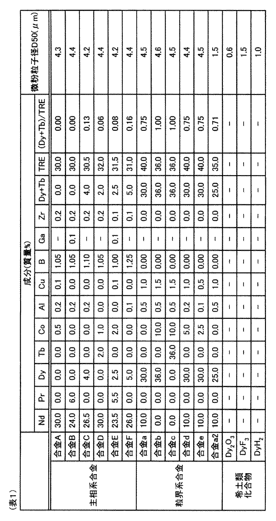
[実施例1~33、比較例1~6、8~12]
次いで、表3に示す通りに希土類焼結磁石を作製した。これらの原料合金(合金A~合金F、合金a~合金e)に室温で水素吸蔵処理を施した後に、Ar雰囲気中で600℃で1時間、脱水素処理を行って主相系合金(合金A~合金F)及び粒界相系合金(合金a~合金e)を粗粉砕した。それぞれ水素粉砕により粗粉砕した後、粗粉砕した主相系合金(合金A~合金F)及び粒界相系合金(合金a~合金e)に、粉砕助剤としてオレイン酸アミドを0.1wt%程度添加し、高圧N2ガスによるジェットミル粉砕を行い、それぞれ平均粒子径が4.2μm~4.6μm程度の微粉末とした。また、水素粉砕以降焼結処理するまでは酸素雰囲気は200ppm程度として行った。次いで、得られた主相系合金(合金A~合金F)の微粉末と、粒界相系合金(合金a~合金e、a2)の微粉末又は希土類化合物(Dy2O3、DyF3、DyH2)の微粉末とを、質量比が表2に示す配合比となるように低酸素雰囲気で混合し、希土類焼結磁石の原料粉末である混合粉末を得た。次いで、得られた混合粉末を、成形圧力が118MPa、配向磁場が1200kA/mの条件で磁場中で成形を行い、成形体を得た。
また、比較例7では、合金Eのみを用いたこと以外は、実施例1と同様の条件で行い、希土類焼結磁石を作製した。
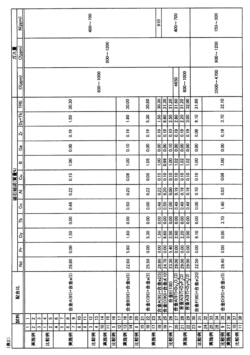
製造した希土類焼結磁石の相対密度、一部で3層構造が形成されている主相粒子(低濃度領域の少なくとも一部に高濃度領域が隣接し、かつ高濃度領域の少なくとも一部に中濃度領域が隣接している主相粒子)の割合、完全に3層構造が形成されている主相粒子(低濃度領域の周囲全てに高濃度領域が隣接し、かつ高濃度領域の周囲全てに中濃度領域が隣接している主相粒子)の割合、磁気特性、強度、温度特性、耐食性および中濃度領域内のDy又はTbの濃度の平均値を以下の方法で測定し、評価した。
作製した希土類焼結磁石の相対密度は、希土類焼結磁石の実測密度をその理論密度で除した値である。本実施例においては、希土類焼結磁石の理論密度はR2Fe14Bの密度とし、Nd2Fe14Bは7.58Mg/m3とし、Dy2Fe14Bは8.07Mg/m3とした。また、元素Rを2種類以上用いる場合には、各元素の比率に応じ直線近似する。具体的には、元素RとしてNdおよびDyを用い、これらのモル比がNd:Dy=x:yである場合、希土類焼結磁石の理論密度は(7.58×+8.07y)/(x+y)とする。
希土類焼結磁石の試料を準備して70個以上の主相粒子をEPMAで観察した。希土類焼結磁石の主相に含まれる重希土類元素の濃度を確認し、一部で3層構造が形成されている主相粒子の割合、完全に3層構造が形成されている主相粒子の割合を求めた。一部で3層構造が形成されている主相粒子の割合と完全に3層構造が形成されている主相粒子の割合とは、試料ごとに所定の数の主相粒子を観察して、その中に含まれる一部で3層構造が形成されている主相粒子又は完全に3層構造が形成されている主相粒子の数から求めた。
製造した希土類焼結磁石の磁石特性は、BHトレーサーにより測定して保磁力HcJ、残留磁束密度Brを求めた。
製造した希土類焼結磁石を40mm×10mm×2mmの試験片に加工し、3点曲げ強度試験を行った。3点曲げ強度試験は、JIS R1601に準拠し、万能試験機(商品名「AGS−1000A」、島津製作所社製)で評価した。図13に3点曲げ強度試験の一例を模式的に示す。図13に示すように、基板41上に一対の支点42を設置し、支点間距離を30mmとした。一対の支点42上に試験片Sを設置して試験片Sに荷重を加えて行った。
温度可変型の磁気測定装置を使用し、室温RT(22℃前後)における保磁力HcJと、所定温度として140℃、180℃、200℃における保磁力HcJを比較し比率(%)を計算した。
製造した希土類焼結磁石を内周スライサーで10mm×10mm×2mmに加工し、洗浄した試験片を試料とした。この試料を、温度を60℃とし、湿度を90%RHとした恒温恒湿槽に2000時間入れた後、試験片の外観の変化を確認し、錆の有無を評価した。試験片は100個(n=100)用意し、各試験片について行った。なお、表4中、分母は、錆の有無を観察した試験片の数を示し、分子は、錆が観察された試験片の数を示す。
また、表4に示す希土類焼結磁石の主相をEPMAでライン分析した際に、主相粒子内の低濃度領域内のDy又はTbの最小濃度をαとし、高濃度領域内のDy又はTbの最大濃度をβとし、中濃度領域におけるDy又はTbの濃度の平均値を、Dy又はTbの最大濃度から粒界相までの重希土類元素の濃度の平均値をγとした時、下記の数式(A)の値を求めた。そして、それぞれの主相粒子の下記の数式(A)から、それぞれの希土類焼結磁石の主相粒子内の中濃度領域のDy又はTbの濃度の平均値を求めた。希土類焼結磁石の主相内の中濃度領域内のDy又はTbの濃度の平均値と、表3、4に示す希土類焼結磁石の温度特性、強度および耐食性との関係を図14~図19に示す。



12 低濃度領域
13 高濃度領域
14 中濃度領域
15 粒界相
20 SPMモータ
21 ハウジング
22 ロータ
23 ステータ
24 回転軸
25 ロータコア(鉄芯)
26 永久磁石
27 磁石挿入スロット
28 ステータコア
29 スロットル
30 コイル
41 基板
42 支点
S 試験片
Claims (13)
- R2T14B(RはNd、Prの何れか一方又は両方を主成分として含む1種以上の希土類元素であり、TはFe又はFe及びCoを含む1種以上の遷移元素を表す)化合物からなる主相と、前記主相よりRを多く含む粒界相とを少なくとも含む希土類焼結磁石であり、
前記主相は、重希土類元素(少なくともDy、Tbの何れか一方又は両方を含む)を含み、
前記希土類焼結磁石に含まれる前記主相のうちの少なくとも1部の主相粒子は、前記重希土類元素の濃度が異なる少なくとも3つの領域を含み、
前記重希土類元素の濃度の異なる3つの領域は、
前記重希土類元素の濃度が3つの領域において最も低い低濃度領域と、
前記重希土類元素の濃度が3つの領域において最も高い高濃度領域と、
前記重希土類元素の濃度が前記低濃度領域より高く、前記高濃度領域よりも低い中濃度領域とであり、
前記3つの領域は、前記主相粒子内において前記低濃度領域から前記粒界相へ向かって、前記低濃度領域、前記高濃度領域、前記中濃度領域の順に存在していることを特徴とする希土類焼結磁石。 - 前記低濃度領域の少なくとも一部に前記高濃度領域が隣接し、かつ前記高濃度領域の少なくとも一部に前記中濃度領域が隣接している主相粒子が、前記希土類焼結磁石中に5%以上存在している請求項1に記載の希土類焼結磁石。
- 前記主相粒子が、前記希土類焼結磁石中に30%以上存在している請求項2に記載の希土類焼結磁石。
- 前記低濃度領域の周囲全てに前記高濃度領域が隣接し、かつ前記高濃度領域の周囲全てに前記中濃度領域が隣接している主相粒子が、前記希土類焼結磁石中に3%以上存在している請求項1乃至3の何れか1つに記載の希土類焼結磁石。
- 前記主相粒子が前記希土類焼結磁石中に5%以上存在している請求項4に記載の希土類焼結磁石。
- 前記中濃度領域における前記重希土類元素の濃度の平均値を、前記重希土類元素の最大濃度から前記粒界相までの前記重希土類元素の濃度の平均値とする請求項1乃至5の何れか1つに記載の希土類焼結磁石。
- 前記主相内における前記重希土類元素の最小濃度をαとし、前記主相内における前記重希土類元素の最大濃度をβとし、前記中濃度領域における前記重希土類元素の濃度の平均値をγとした時、
前記中濃度領域における前記重希土類元素の濃度の平均値は下記数式(A)で表され、
下記数式(A)の値が0.2以上0.8以下の範囲内である請求項6に記載の希土類焼結磁石。

- 前記数式(A)の値が0.3以上0.75以下の範囲内である請求項7に記載の希土類焼結磁石。
- 前記数式(A)の値が0.35以上0.7以下の範囲内である請求項7に記載の希土類焼結磁石。
- R2T14B化合物を含む主相系合金と、HR(HRはDy、Tbの何れか一方又は両方を少なくとも含む1種以上の希土類元素を表す)及びTを少なくとも含む粒界相系合金とを原料合金として用いる請求項1乃至9の何れか1つに記載の希土類焼結磁石。
- 前記希土類焼結磁石の相対密度は99%以上である請求項1乃至10の何れか1つに記載の希土類焼結磁石。
- R2T14B(RはNd、Prの何れか一方又は両方を主成分として含む1種以上の希土類元素であり、TはFe又はFe及びCoを含む1種以上の遷移元素を表す)化合物からなる主相と、前記主相よりRを多く含む粒界相とを少なくとも含む希土類焼結磁石を製造するにあたり、
R2T14B化合物を含む主相系合金の合金粉末と、HR(HRはDy、Tbの何れか一方又は両方を少なくとも含む1種以上の希土類元素を表す)及びTを少なくとも含む粒界相系合金の合金粉末とを混合し、混合物を得る混合物作製工程と、
前記混合物を成形し、成形体を得る成形工程と、
600℃以上焼結温度までにおける平均昇温速度を2℃/min以上10℃/min以下として前記成形体を昇温する昇温工程と、
前記成形体を焼結し、焼結体を得る焼結工程と、
焼結温度から600℃までの平均冷却速度を3℃/min以上20℃/min未満として前記焼結体を冷却する冷却工程と、
を含み、
前記主相には重希土類元素(少なくともDy、Tbの何れか一方又は両方を含む)を含み、
前記希土類焼結磁石に含まれる前記主相のうちの少なくとも1部の主相粒子は、前記重希土類元素の濃度が異なる少なくとも3つの領域を含み、
前記重希土類元素の濃度の異なる3つの領域は、
前記重希土類元素の濃度が3つの領域において最も低い低濃度領域と、
前記重希土類元素の濃度が3つの領域において最も高い高濃度領域と、
前記重希土類元素の濃度が前記低濃度領域より高く、前記高濃度領域よりも低い中濃度領域とであり、
前記3つの領域は、前記主相粒子内において前記低濃度領域から前記粒界相へ向かって、前記低濃度領域、前記高濃度領域、前記中濃度領域の順に存在していることを特徴とする希土類焼結磁石の製造方法。 - 請求項1乃至11の何れか1つに記載の希土類焼結磁石を含むことを特徴とする回転機。
Priority Applications (4)
| Application Number | Priority Date | Filing Date | Title |
|---|---|---|---|
| DE112012002220.3T DE112012002220T5 (de) | 2011-05-25 | 2012-05-25 | Gesinterte Selten-Erd-Magnete, Verfahren zur Herstellung derselben, und eine rotierende Maschine |
| JP2013516480A JP5447736B2 (ja) | 2011-05-25 | 2012-05-25 | 希土類焼結磁石、希土類焼結磁石の製造方法及び回転機 |
| US14/119,354 US9177705B2 (en) | 2011-05-25 | 2012-05-25 | Sintered rare earth magnet, method of producing the same, and rotating machine |
| CN201280024974.2A CN103620707A (zh) | 2011-05-25 | 2012-05-25 | 稀土类烧结磁体、稀土类烧结磁体的制造方法以及旋转电机 |
Applications Claiming Priority (2)
| Application Number | Priority Date | Filing Date | Title |
|---|---|---|---|
| JP2011117447 | 2011-05-25 | ||
| JP2011-117447 | 2011-05-25 |
Publications (1)
| Publication Number | Publication Date |
|---|---|
| WO2012161355A1 true WO2012161355A1 (ja) | 2012-11-29 |
Family
ID=47217412
Family Applications (1)
| Application Number | Title | Priority Date | Filing Date |
|---|---|---|---|
| PCT/JP2012/064254 Ceased WO2012161355A1 (ja) | 2011-05-25 | 2012-05-25 | 希土類焼結磁石、希土類焼結磁石の製造方法及び回転機 |
Country Status (5)
| Country | Link |
|---|---|
| US (1) | US9177705B2 (ja) |
| JP (1) | JP5447736B2 (ja) |
| CN (1) | CN103620707A (ja) |
| DE (1) | DE112012002220T5 (ja) |
| WO (1) | WO2012161355A1 (ja) |
Cited By (18)
| Publication number | Priority date | Publication date | Assignee | Title |
|---|---|---|---|---|
| GB2506683A (en) * | 2012-10-08 | 2014-04-09 | Vacuumschmelze Gmbh & Co Kg | Anisotropic soft magnetic article and method for its production |
| JP2014130888A (ja) * | 2012-12-28 | 2014-07-10 | Hitachi Metals Ltd | R−t−b系焼結磁石およびその製造方法 |
| JP2014148738A (ja) * | 2013-02-01 | 2014-08-21 | Kankyo Joka Kenkyusho:Kk | 希土類元素を含有した溶液から希土類元素及び酸の分離回収方法 |
| JP2014199845A (ja) * | 2013-03-29 | 2014-10-23 | Tdk株式会社 | 金属粉末含有樹脂成形体用組成物の製造方法、予備成形体、金属焼結体の製造方法および希土類焼結磁石 |
| WO2015030231A1 (ja) * | 2013-09-02 | 2015-03-05 | 日立金属株式会社 | R-t-b系焼結磁石の製造方法 |
| JP2016154219A (ja) * | 2015-02-16 | 2016-08-25 | Tdk株式会社 | 希土類系永久磁石 |
| WO2017110680A1 (ja) * | 2015-12-24 | 2017-06-29 | 日立金属株式会社 | R-t-b系焼結磁石の製造方法 |
| CN107077965A (zh) * | 2015-07-30 | 2017-08-18 | 日立金属株式会社 | R‑t‑b系烧结磁体的制造方法 |
| JP2017147426A (ja) * | 2015-03-31 | 2017-08-24 | 信越化学工業株式会社 | R−Fe−B系焼結磁石及びその製造方法 |
| JP2017532770A (ja) * | 2014-08-15 | 2017-11-02 | アーバン マイニング カンパニー | 粒界工学 |
| JP2017228771A (ja) * | 2016-06-20 | 2017-12-28 | 信越化学工業株式会社 | R−Fe−B系焼結磁石及びその製造方法 |
| US20180301256A1 (en) * | 2017-03-30 | 2018-10-18 | Tdk Corporation | R-t-b based sintered magnet |
| JP2018174314A (ja) * | 2017-03-30 | 2018-11-08 | Tdk株式会社 | R−t−b系焼結磁石 |
| JP2018174313A (ja) * | 2017-03-30 | 2018-11-08 | Tdk株式会社 | R−t−b系焼結磁石 |
| JP2019519941A (ja) * | 2016-05-02 | 2019-07-11 | 星林先端産業株式会社Star Group Ind. Co., Ltd | 希土類焼結磁石の製造方法 |
| DE102014103210B4 (de) * | 2013-03-15 | 2020-03-19 | GM Global Technology Operations LLC (n. d. Gesetzen des Staates Delaware) | Herstellen von nd-fe-b-magneten unter verwendung von heisspressen mit verringertem dysprosium oder terbium |
| JP2020057734A (ja) * | 2018-10-04 | 2020-04-09 | 信越化学工業株式会社 | 希土類焼結磁石 |
| JP2022511483A (ja) * | 2019-09-26 | 2022-01-31 | エルジー・ケム・リミテッド | 焼結磁石の製造方法および焼結磁石 |
Families Citing this family (16)
| Publication number | Priority date | Publication date | Assignee | Title |
|---|---|---|---|---|
| JP5870522B2 (ja) * | 2010-07-14 | 2016-03-01 | トヨタ自動車株式会社 | 永久磁石の製造方法 |
| US10186374B2 (en) * | 2013-03-15 | 2019-01-22 | GM Global Technology Operations LLC | Manufacturing Nd—Fe—B magnets using hot pressing with reduced dysprosium or terbium |
| CN103990806B (zh) * | 2014-05-11 | 2016-05-25 | 沈阳中北通磁科技股份有限公司 | 一种钕铁硼稀土永磁合金的氢破碎方法和设备 |
| CN103990805B (zh) * | 2014-05-11 | 2016-06-22 | 沈阳中北通磁科技股份有限公司 | 一种钕铁硼稀土永磁合金的制粉方法和设备 |
| CN103996520B (zh) * | 2014-05-11 | 2016-10-05 | 沈阳中北通磁科技股份有限公司 | 一种钕铁硼稀土永磁体的烧结方法和设备 |
| JP6500907B2 (ja) * | 2014-09-17 | 2019-04-17 | 日立金属株式会社 | R−t−b系焼結磁石の製造方法 |
| CN104333156B (zh) * | 2014-11-25 | 2017-02-08 | 盐城工学院 | 高效微电机的转子磁环及其制备方法 |
| CN105469973B (zh) | 2014-12-19 | 2017-07-18 | 北京中科三环高技术股份有限公司 | 一种r‑t‑b永磁体的制备方法 |
| US10256017B2 (en) * | 2015-02-16 | 2019-04-09 | Tdk Corporation | Rare earth based permanent magnet |
| JP6424664B2 (ja) | 2015-02-16 | 2018-11-21 | Tdk株式会社 | 希土類系永久磁石 |
| RU2704989C2 (ru) * | 2015-03-31 | 2019-11-01 | Син-Эцу Кемикал Ко., Лтд. | Спеченный магнит r-fe-b и способ его изготовления |
| RU2697265C2 (ru) * | 2015-03-31 | 2019-08-13 | Син-Эцу Кемикал Ко., Лтд. | Спеченный магнит R-Fe-B и способ его изготовления |
| JP6784484B2 (ja) * | 2015-09-11 | 2020-11-11 | Tdk株式会社 | R−t−b系焼結磁石およびモータ |
| JP6488976B2 (ja) * | 2015-10-07 | 2019-03-27 | Tdk株式会社 | R−t−b系焼結磁石 |
| DE102017223268A1 (de) * | 2017-12-19 | 2019-06-19 | Robert Bosch Gmbh | Verfahren zur Herstellung eines magnetischen Materials, magnetisches Material, Hartmagnet, Elektromotor, Starter und Generator |
| CN116391243A (zh) * | 2020-11-17 | 2023-07-04 | 三菱电机株式会社 | 稀土烧结磁体、稀土烧结磁体的制造方法、转子和旋转机 |
Citations (5)
| Publication number | Priority date | Publication date | Assignee | Title |
|---|---|---|---|---|
| JPH07122413A (ja) * | 1993-10-28 | 1995-05-12 | Hitachi Metals Ltd | 希土類永久磁石およびその製造方法 |
| JP2001230107A (ja) * | 2000-02-15 | 2001-08-24 | Shin Etsu Chem Co Ltd | 耐食性希土類磁石 |
| JP2006210450A (ja) * | 2005-01-26 | 2006-08-10 | Tdk Corp | R−t−b系焼結磁石 |
| JP2007294917A (ja) * | 2006-03-27 | 2007-11-08 | Tdk Corp | R−t−b系焼結磁石及びr−t−b系焼結磁石の製造方法 |
| WO2010082492A1 (ja) * | 2009-01-16 | 2010-07-22 | 日立金属株式会社 | R-t-b系焼結磁石の製造方法 |
Family Cites Families (9)
| Publication number | Priority date | Publication date | Assignee | Title |
|---|---|---|---|---|
| EP0778594B1 (en) * | 1995-06-26 | 2004-09-29 | Neomax Co., Ltd. | Process for producing sintered rare earth magnet |
| JPH10140211A (ja) | 1996-11-14 | 1998-05-26 | Nok Corp | 磁性材料の製造法 |
| JP2001217112A (ja) | 2000-01-31 | 2001-08-10 | Hitachi Metals Ltd | R−t−b系焼結磁石 |
| JP3997413B2 (ja) * | 2002-11-14 | 2007-10-24 | 信越化学工業株式会社 | R−Fe−B系焼結磁石及びその製造方法 |
| US7618497B2 (en) * | 2003-06-30 | 2009-11-17 | Tdk Corporation | R-T-B based rare earth permanent magnet and method for production thereof |
| US8123832B2 (en) | 2005-03-14 | 2012-02-28 | Tdk Corporation | R-T-B system sintered magnet |
| JP2007266199A (ja) | 2006-03-28 | 2007-10-11 | Tdk Corp | 希土類焼結磁石の製造方法 |
| EP2178096B1 (en) | 2007-07-27 | 2015-12-23 | Hitachi Metals, Ltd. | R-Fe-B RARE EARTH SINTERED MAGNET |
| CN101685695B (zh) * | 2008-09-27 | 2012-06-13 | 宁波科宁达工业有限公司 | 一种用于批量大件钕铁硼磁体的烧结方法 |
-
2012
- 2012-05-25 CN CN201280024974.2A patent/CN103620707A/zh active Pending
- 2012-05-25 DE DE112012002220.3T patent/DE112012002220T5/de not_active Ceased
- 2012-05-25 WO PCT/JP2012/064254 patent/WO2012161355A1/ja not_active Ceased
- 2012-05-25 US US14/119,354 patent/US9177705B2/en active Active
- 2012-05-25 JP JP2013516480A patent/JP5447736B2/ja active Active
Patent Citations (5)
| Publication number | Priority date | Publication date | Assignee | Title |
|---|---|---|---|---|
| JPH07122413A (ja) * | 1993-10-28 | 1995-05-12 | Hitachi Metals Ltd | 希土類永久磁石およびその製造方法 |
| JP2001230107A (ja) * | 2000-02-15 | 2001-08-24 | Shin Etsu Chem Co Ltd | 耐食性希土類磁石 |
| JP2006210450A (ja) * | 2005-01-26 | 2006-08-10 | Tdk Corp | R−t−b系焼結磁石 |
| JP2007294917A (ja) * | 2006-03-27 | 2007-11-08 | Tdk Corp | R−t−b系焼結磁石及びr−t−b系焼結磁石の製造方法 |
| WO2010082492A1 (ja) * | 2009-01-16 | 2010-07-22 | 日立金属株式会社 | R-t-b系焼結磁石の製造方法 |
Cited By (39)
| Publication number | Priority date | Publication date | Assignee | Title |
|---|---|---|---|---|
| GB2506683A (en) * | 2012-10-08 | 2014-04-09 | Vacuumschmelze Gmbh & Co Kg | Anisotropic soft magnetic article and method for its production |
| JP2014130888A (ja) * | 2012-12-28 | 2014-07-10 | Hitachi Metals Ltd | R−t−b系焼結磁石およびその製造方法 |
| JP2014148738A (ja) * | 2013-02-01 | 2014-08-21 | Kankyo Joka Kenkyusho:Kk | 希土類元素を含有した溶液から希土類元素及び酸の分離回収方法 |
| DE102014103210B4 (de) * | 2013-03-15 | 2020-03-19 | GM Global Technology Operations LLC (n. d. Gesetzen des Staates Delaware) | Herstellen von nd-fe-b-magneten unter verwendung von heisspressen mit verringertem dysprosium oder terbium |
| JP2014199845A (ja) * | 2013-03-29 | 2014-10-23 | Tdk株式会社 | 金属粉末含有樹脂成形体用組成物の製造方法、予備成形体、金属焼結体の製造方法および希土類焼結磁石 |
| CN105474337B (zh) * | 2013-09-02 | 2017-12-08 | 日立金属株式会社 | R‑t‑b系烧结磁体的制造方法 |
| WO2015030231A1 (ja) * | 2013-09-02 | 2015-03-05 | 日立金属株式会社 | R-t-b系焼結磁石の製造方法 |
| CN105474337A (zh) * | 2013-09-02 | 2016-04-06 | 日立金属株式会社 | R-t-b系烧结磁体的制造方法 |
| US10658108B2 (en) | 2013-09-02 | 2020-05-19 | Hitachi Metals, Ltd. | Method for producing R-T-B based sintered magnet |
| JPWO2015030231A1 (ja) * | 2013-09-02 | 2017-03-02 | 日立金属株式会社 | R−t−b系焼結磁石の製造方法 |
| US11270841B2 (en) | 2014-08-15 | 2022-03-08 | Urban Mining Company | Grain boundary engineering |
| JP7223182B2 (ja) | 2014-08-15 | 2023-02-15 | ノヴェオン マグネティックス,インク. | 粒界工学 |
| JP2017532770A (ja) * | 2014-08-15 | 2017-11-02 | アーバン マイニング カンパニー | 粒界工学 |
| JP2022068218A (ja) * | 2014-08-15 | 2022-05-09 | ノヴェオン マグネティックス,インク. | 粒界工学 |
| JP2023062006A (ja) * | 2014-08-15 | 2023-05-02 | ノヴェオン マグネティックス,インク. | 粒界工学 |
| JP7021269B2 (ja) | 2014-08-15 | 2022-02-16 | アーバン マイニング カンパニー | 粒界工学 |
| JP2020098926A (ja) * | 2014-08-15 | 2020-06-25 | アーバン マイニング カンパニー | 粒界工学 |
| JP7592113B2 (ja) | 2014-08-15 | 2024-11-29 | ノヴェオン マグネティックス,インク. | 粒界工学 |
| JP2016154219A (ja) * | 2015-02-16 | 2016-08-25 | Tdk株式会社 | 希土類系永久磁石 |
| JP2017147426A (ja) * | 2015-03-31 | 2017-08-24 | 信越化学工業株式会社 | R−Fe−B系焼結磁石及びその製造方法 |
| CN107077965B (zh) * | 2015-07-30 | 2018-12-28 | 日立金属株式会社 | R-t-b系烧结磁体的制造方法 |
| CN107077965A (zh) * | 2015-07-30 | 2017-08-18 | 日立金属株式会社 | R‑t‑b系烧结磁体的制造方法 |
| US11177069B2 (en) | 2015-07-30 | 2021-11-16 | Hitachi Metals, Ltd. | Method for producing R-T-B system sintered magnet |
| WO2017110680A1 (ja) * | 2015-12-24 | 2017-06-29 | 日立金属株式会社 | R-t-b系焼結磁石の製造方法 |
| US10242781B2 (en) | 2015-12-24 | 2019-03-26 | Hitachi Metals, Ltd. | Method for manufacturing R-T-B based sintered magnet |
| JP6213697B1 (ja) * | 2015-12-24 | 2017-10-18 | 日立金属株式会社 | R−t−b系焼結磁石の製造方法 |
| JP2019519941A (ja) * | 2016-05-02 | 2019-07-11 | 星林先端産業株式会社Star Group Ind. Co., Ltd | 希土類焼結磁石の製造方法 |
| JP2017228771A (ja) * | 2016-06-20 | 2017-12-28 | 信越化学工業株式会社 | R−Fe−B系焼結磁石及びその製造方法 |
| US20180301256A1 (en) * | 2017-03-30 | 2018-10-18 | Tdk Corporation | R-t-b based sintered magnet |
| JP2018174314A (ja) * | 2017-03-30 | 2018-11-08 | Tdk株式会社 | R−t−b系焼結磁石 |
| JP7035683B2 (ja) | 2017-03-30 | 2022-03-15 | Tdk株式会社 | R-t-b系焼結磁石 |
| JP7143605B2 (ja) | 2017-03-30 | 2022-09-29 | Tdk株式会社 | R-t-b系焼結磁石 |
| US10748685B2 (en) * | 2017-03-30 | 2020-08-18 | Tdk Corporation | R-T-B based sintered magnet |
| JP2018174313A (ja) * | 2017-03-30 | 2018-11-08 | Tdk株式会社 | R−t−b系焼結磁石 |
| JP7196514B2 (ja) | 2018-10-04 | 2022-12-27 | 信越化学工業株式会社 | 希土類焼結磁石 |
| US11798716B2 (en) | 2018-10-04 | 2023-10-24 | Shin-Etsu Chemical Co., Ltd. | Rare earth sintered magnet |
| JP2020057734A (ja) * | 2018-10-04 | 2020-04-09 | 信越化学工業株式会社 | 希土類焼結磁石 |
| JP2022511483A (ja) * | 2019-09-26 | 2022-01-31 | エルジー・ケム・リミテッド | 焼結磁石の製造方法および焼結磁石 |
| JP7158807B2 (ja) | 2019-09-26 | 2022-10-24 | エルジー・ケム・リミテッド | 焼結磁石の製造方法および焼結磁石 |
Also Published As
| Publication number | Publication date |
|---|---|
| JPWO2012161355A1 (ja) | 2014-07-31 |
| JP5447736B2 (ja) | 2014-03-19 |
| CN103620707A (zh) | 2014-03-05 |
| DE112012002220T5 (de) | 2014-07-17 |
| US9177705B2 (en) | 2015-11-03 |
| US20140184370A1 (en) | 2014-07-03 |
Similar Documents
| Publication | Publication Date | Title |
|---|---|---|
| JP5447736B2 (ja) | 希土類焼結磁石、希土類焼結磁石の製造方法及び回転機 | |
| JP6274216B2 (ja) | R−t−b系焼結磁石、および、モータ | |
| CN105453196B (zh) | R‑t‑b系烧结磁铁以及电动机 | |
| JP6330813B2 (ja) | R−t−b系焼結磁石、および、モータ | |
| JP5392440B1 (ja) | R−t−b系焼結磁石 | |
| JP6274214B2 (ja) | R−t−b系焼結磁石、および回転機 | |
| JP5397575B1 (ja) | R−t−b系焼結磁石 | |
| JP6572550B2 (ja) | R−t−b系焼結磁石 | |
| US10096410B2 (en) | R-T-B based sintered magnet | |
| JP7379837B2 (ja) | R-t-b系永久磁石 | |
| JP6399307B2 (ja) | R−t−b系焼結磁石 | |
| CN108064407B (zh) | 永久磁铁、旋转电机、以及车辆 | |
| JP2012212808A (ja) | 希土類焼結磁石の製造方法 | |
| JP6642184B2 (ja) | R−t−b系焼結磁石 | |
| JP2016096182A (ja) | R−t−b系焼結磁石 |
Legal Events
| Date | Code | Title | Description |
|---|---|---|---|
| 121 | Ep: the epo has been informed by wipo that ep was designated in this application |
Ref document number: 12789688 Country of ref document: EP Kind code of ref document: A1 |
|
| DPE1 | Request for preliminary examination filed after expiration of 19th month from priority date (pct application filed from 20040101) | ||
| ENP | Entry into the national phase |
Ref document number: 2013516480 Country of ref document: JP Kind code of ref document: A |
|
| WWE | Wipo information: entry into national phase |
Ref document number: 1120120022203 Country of ref document: DE Ref document number: 112012002220 Country of ref document: DE |
|
| WWE | Wipo information: entry into national phase |
Ref document number: 14119354 Country of ref document: US |
|
| 122 | Ep: pct application non-entry in european phase |
Ref document number: 12789688 Country of ref document: EP Kind code of ref document: A1 |