WO2012157089A1 - クランキングトルク制御装置 - Google Patents
クランキングトルク制御装置 Download PDFInfo
- Publication number
- WO2012157089A1 WO2012157089A1 PCT/JP2011/061409 JP2011061409W WO2012157089A1 WO 2012157089 A1 WO2012157089 A1 WO 2012157089A1 JP 2011061409 W JP2011061409 W JP 2011061409W WO 2012157089 A1 WO2012157089 A1 WO 2012157089A1
- Authority
- WO
- WIPO (PCT)
- Prior art keywords
- engine
- battery
- motor
- output
- voltage
- Prior art date
- Legal status (The legal status is an assumption and is not a legal conclusion. Google has not performed a legal analysis and makes no representation as to the accuracy of the status listed.)
- Ceased
Links
Images



Classifications
-
- B—PERFORMING OPERATIONS; TRANSPORTING
- B60—VEHICLES IN GENERAL
- B60W—CONJOINT CONTROL OF VEHICLE SUB-UNITS OF DIFFERENT TYPE OR DIFFERENT FUNCTION; CONTROL SYSTEMS SPECIALLY ADAPTED FOR HYBRID VEHICLES; ROAD VEHICLE DRIVE CONTROL SYSTEMS FOR PURPOSES NOT RELATED TO THE CONTROL OF A PARTICULAR SUB-UNIT
- B60W20/00—Control systems specially adapted for hybrid vehicles
- B60W20/10—Controlling the power contribution of each of the prime movers to meet required power demand
- B60W20/13—Controlling the power contribution of each of the prime movers to meet required power demand in order to stay within battery power input or output limits; in order to prevent overcharging or battery depletion
-
- B—PERFORMING OPERATIONS; TRANSPORTING
- B60—VEHICLES IN GENERAL
- B60K—ARRANGEMENT OR MOUNTING OF PROPULSION UNITS OR OF TRANSMISSIONS IN VEHICLES; ARRANGEMENT OR MOUNTING OF PLURAL DIVERSE PRIME-MOVERS IN VEHICLES; AUXILIARY DRIVES FOR VEHICLES; INSTRUMENTATION OR DASHBOARDS FOR VEHICLES; ARRANGEMENTS IN CONNECTION WITH COOLING, AIR INTAKE, GAS EXHAUST OR FUEL SUPPLY OF PROPULSION UNITS IN VEHICLES
- B60K6/00—Arrangement or mounting of plural diverse prime-movers for mutual or common propulsion, e.g. hybrid propulsion systems comprising electric motors and internal combustion engines
- B60K6/20—Arrangement or mounting of plural diverse prime-movers for mutual or common propulsion, e.g. hybrid propulsion systems comprising electric motors and internal combustion engines the prime-movers consisting of electric motors and internal combustion engines, e.g. HEVs
- B60K6/42—Arrangement or mounting of plural diverse prime-movers for mutual or common propulsion, e.g. hybrid propulsion systems comprising electric motors and internal combustion engines the prime-movers consisting of electric motors and internal combustion engines, e.g. HEVs characterised by the architecture of the hybrid electric vehicle
- B60K6/44—Series-parallel type
- B60K6/445—Differential gearing distribution type
-
- B—PERFORMING OPERATIONS; TRANSPORTING
- B60—VEHICLES IN GENERAL
- B60W—CONJOINT CONTROL OF VEHICLE SUB-UNITS OF DIFFERENT TYPE OR DIFFERENT FUNCTION; CONTROL SYSTEMS SPECIALLY ADAPTED FOR HYBRID VEHICLES; ROAD VEHICLE DRIVE CONTROL SYSTEMS FOR PURPOSES NOT RELATED TO THE CONTROL OF A PARTICULAR SUB-UNIT
- B60W10/00—Conjoint control of vehicle sub-units of different type or different function
- B60W10/04—Conjoint control of vehicle sub-units of different type or different function including control of propulsion units
- B60W10/06—Conjoint control of vehicle sub-units of different type or different function including control of propulsion units including control of combustion engines
-
- B—PERFORMING OPERATIONS; TRANSPORTING
- B60—VEHICLES IN GENERAL
- B60W—CONJOINT CONTROL OF VEHICLE SUB-UNITS OF DIFFERENT TYPE OR DIFFERENT FUNCTION; CONTROL SYSTEMS SPECIALLY ADAPTED FOR HYBRID VEHICLES; ROAD VEHICLE DRIVE CONTROL SYSTEMS FOR PURPOSES NOT RELATED TO THE CONTROL OF A PARTICULAR SUB-UNIT
- B60W10/00—Conjoint control of vehicle sub-units of different type or different function
- B60W10/04—Conjoint control of vehicle sub-units of different type or different function including control of propulsion units
- B60W10/08—Conjoint control of vehicle sub-units of different type or different function including control of propulsion units including control of electric propulsion units, e.g. motors or generators
-
- B—PERFORMING OPERATIONS; TRANSPORTING
- B60—VEHICLES IN GENERAL
- B60W—CONJOINT CONTROL OF VEHICLE SUB-UNITS OF DIFFERENT TYPE OR DIFFERENT FUNCTION; CONTROL SYSTEMS SPECIALLY ADAPTED FOR HYBRID VEHICLES; ROAD VEHICLE DRIVE CONTROL SYSTEMS FOR PURPOSES NOT RELATED TO THE CONTROL OF A PARTICULAR SUB-UNIT
- B60W10/00—Conjoint control of vehicle sub-units of different type or different function
- B60W10/24—Conjoint control of vehicle sub-units of different type or different function including control of energy storage means
- B60W10/26—Conjoint control of vehicle sub-units of different type or different function including control of energy storage means for electrical energy, e.g. batteries or capacitors
-
- B—PERFORMING OPERATIONS; TRANSPORTING
- B60—VEHICLES IN GENERAL
- B60W—CONJOINT CONTROL OF VEHICLE SUB-UNITS OF DIFFERENT TYPE OR DIFFERENT FUNCTION; CONTROL SYSTEMS SPECIALLY ADAPTED FOR HYBRID VEHICLES; ROAD VEHICLE DRIVE CONTROL SYSTEMS FOR PURPOSES NOT RELATED TO THE CONTROL OF A PARTICULAR SUB-UNIT
- B60W20/00—Control systems specially adapted for hybrid vehicles
-
- B—PERFORMING OPERATIONS; TRANSPORTING
- B60—VEHICLES IN GENERAL
- B60W—CONJOINT CONTROL OF VEHICLE SUB-UNITS OF DIFFERENT TYPE OR DIFFERENT FUNCTION; CONTROL SYSTEMS SPECIALLY ADAPTED FOR HYBRID VEHICLES; ROAD VEHICLE DRIVE CONTROL SYSTEMS FOR PURPOSES NOT RELATED TO THE CONTROL OF A PARTICULAR SUB-UNIT
- B60W20/00—Control systems specially adapted for hybrid vehicles
- B60W20/40—Controlling the engagement or disengagement of prime movers, e.g. for transition between prime movers
-
- B—PERFORMING OPERATIONS; TRANSPORTING
- B60—VEHICLES IN GENERAL
- B60W—CONJOINT CONTROL OF VEHICLE SUB-UNITS OF DIFFERENT TYPE OR DIFFERENT FUNCTION; CONTROL SYSTEMS SPECIALLY ADAPTED FOR HYBRID VEHICLES; ROAD VEHICLE DRIVE CONTROL SYSTEMS FOR PURPOSES NOT RELATED TO THE CONTROL OF A PARTICULAR SUB-UNIT
- B60W30/00—Purposes of road vehicle drive control systems not related to the control of a particular sub-unit, e.g. of systems using conjoint control of vehicle sub-units
- B60W30/18—Propelling the vehicle
- B60W30/188—Controlling power parameters of the driveline, e.g. determining the required power
- B60W30/1884—Avoiding stall or overspeed of the engine
-
- B—PERFORMING OPERATIONS; TRANSPORTING
- B60—VEHICLES IN GENERAL
- B60K—ARRANGEMENT OR MOUNTING OF PROPULSION UNITS OR OF TRANSMISSIONS IN VEHICLES; ARRANGEMENT OR MOUNTING OF PLURAL DIVERSE PRIME-MOVERS IN VEHICLES; AUXILIARY DRIVES FOR VEHICLES; INSTRUMENTATION OR DASHBOARDS FOR VEHICLES; ARRANGEMENTS IN CONNECTION WITH COOLING, AIR INTAKE, GAS EXHAUST OR FUEL SUPPLY OF PROPULSION UNITS IN VEHICLES
- B60K6/00—Arrangement or mounting of plural diverse prime-movers for mutual or common propulsion, e.g. hybrid propulsion systems comprising electric motors and internal combustion engines
- B60K6/20—Arrangement or mounting of plural diverse prime-movers for mutual or common propulsion, e.g. hybrid propulsion systems comprising electric motors and internal combustion engines the prime-movers consisting of electric motors and internal combustion engines, e.g. HEVs
- B60K6/22—Arrangement or mounting of plural diverse prime-movers for mutual or common propulsion, e.g. hybrid propulsion systems comprising electric motors and internal combustion engines the prime-movers consisting of electric motors and internal combustion engines, e.g. HEVs characterised by apparatus, components or means specially adapted for HEVs
- B60K6/26—Arrangement or mounting of plural diverse prime-movers for mutual or common propulsion, e.g. hybrid propulsion systems comprising electric motors and internal combustion engines the prime-movers consisting of electric motors and internal combustion engines, e.g. HEVs characterised by apparatus, components or means specially adapted for HEVs characterised by the motors or the generators
- B60K2006/268—Electric drive motor starts the engine, i.e. used as starter motor
-
- B—PERFORMING OPERATIONS; TRANSPORTING
- B60—VEHICLES IN GENERAL
- B60W—CONJOINT CONTROL OF VEHICLE SUB-UNITS OF DIFFERENT TYPE OR DIFFERENT FUNCTION; CONTROL SYSTEMS SPECIALLY ADAPTED FOR HYBRID VEHICLES; ROAD VEHICLE DRIVE CONTROL SYSTEMS FOR PURPOSES NOT RELATED TO THE CONTROL OF A PARTICULAR SUB-UNIT
- B60W2510/00—Input parameters relating to a particular sub-units
- B60W2510/06—Combustion engines, Gas turbines
- B60W2510/0638—Engine speed
-
- B—PERFORMING OPERATIONS; TRANSPORTING
- B60—VEHICLES IN GENERAL
- B60W—CONJOINT CONTROL OF VEHICLE SUB-UNITS OF DIFFERENT TYPE OR DIFFERENT FUNCTION; CONTROL SYSTEMS SPECIALLY ADAPTED FOR HYBRID VEHICLES; ROAD VEHICLE DRIVE CONTROL SYSTEMS FOR PURPOSES NOT RELATED TO THE CONTROL OF A PARTICULAR SUB-UNIT
- B60W2510/00—Input parameters relating to a particular sub-units
- B60W2510/24—Energy storage means
- B60W2510/242—Energy storage means for electrical energy
- B60W2510/244—Charge state
-
- B—PERFORMING OPERATIONS; TRANSPORTING
- B60—VEHICLES IN GENERAL
- B60W—CONJOINT CONTROL OF VEHICLE SUB-UNITS OF DIFFERENT TYPE OR DIFFERENT FUNCTION; CONTROL SYSTEMS SPECIALLY ADAPTED FOR HYBRID VEHICLES; ROAD VEHICLE DRIVE CONTROL SYSTEMS FOR PURPOSES NOT RELATED TO THE CONTROL OF A PARTICULAR SUB-UNIT
- B60W2710/00—Output or target parameters relating to a particular sub-units
- B60W2710/24—Energy storage means
- B60W2710/242—Energy storage means for electrical energy
- B60W2710/248—Current for loading or unloading
-
- Y—GENERAL TAGGING OF NEW TECHNOLOGICAL DEVELOPMENTS; GENERAL TAGGING OF CROSS-SECTIONAL TECHNOLOGIES SPANNING OVER SEVERAL SECTIONS OF THE IPC; TECHNICAL SUBJECTS COVERED BY FORMER USPC CROSS-REFERENCE ART COLLECTIONS [XRACs] AND DIGESTS
- Y02—TECHNOLOGIES OR APPLICATIONS FOR MITIGATION OR ADAPTATION AGAINST CLIMATE CHANGE
- Y02T—CLIMATE CHANGE MITIGATION TECHNOLOGIES RELATED TO TRANSPORTATION
- Y02T10/00—Road transport of goods or passengers
- Y02T10/60—Other road transportation technologies with climate change mitigation effect
- Y02T10/62—Hybrid vehicles
Definitions
- the present invention relates to a technical field of a cranking torque control device that controls a cranking torque of a motor when the engine is cranked by a motor in a vehicle including an engine and a motor such as a hybrid vehicle.
- a device that drives a motor generator so as to crank the engine when a request for switching from an EV (Electric Vehicle) travel mode to an HV (Hybrid Vehicle) travel mode is received.
- the discharge allowable power is derived so that the DC voltage of the battery does not fall below the lower limit voltage, and the torque command value is adjusted so that the power consumption of the motor / generator does not exceed the discharge allowable power.
- the lower limit voltage is temporarily raised when the accelerator opening reaches a predetermined reference value within a predetermined time after the request for switching to the HV traveling mode (Patent Document 2). reference).
- the battery protection is prioritized. There is a technical problem that may cause an engine stall.
- the present invention has been made in view of the above problems, for example.
- a cranking torque control device capable of suppressing the occurrence of an unexpected engine stall caused by the battery voltage being lower than the lower limit voltage of the battery. The issue is to provide.
- a first cranking torque control device of the present invention is coupled to an engine, a motor connected to the engine, and capable of supplying power to the motor.
- a setting means mounted on a hybrid vehicle including a battery, and capable of setting an output limit value that is a limit value of power output from the battery according to a power deviation when the motor cranks the engine; Control means for controlling the setting means so as not to set the output limit value on condition that the voltage of the battery is lower than a lower limit voltage related to the battery due to resonance of the engine; Prepare.
- the cranking torque control device is connected to the engine, a motor that is coupled to the engine, and capable of cranking the engine, and supplies power to the motor. It is mounted on a hybrid vehicle equipped with a battery capable of being used.
- “motor” means a motor for engine control, but it may be a motor realized in a motor generator (electric motor). That is, it may mean a motor generator as long as it can function as a motor.
- the setting means including a memory, a processor, and the like includes an output limit value that is a limit value of the power output from the battery according to the power deviation when the motor cranks the engine (that is, when the engine is started). Can be set.
- power deviation means a deviation between the target input / output power and the actual input / output power. Since various known modes can be applied to the method of setting the output limit value according to the power deviation, the details thereof are omitted for the purpose of preventing the explanation from becoming complicated.
- control means comprising a memory, a processor, etc. is a setting means so as not to set the output limit value on condition that the voltage of the battery is lower than the lower limit voltage related to the battery due to engine resonance.
- engine resonance means a relatively large fluctuation in the engine speed that occurs when the engine speed passes through the resonance band of the power transmission system including the engine.
- the setting means is controlled by the control means so as not to set the output limit value on condition that the battery voltage is lower than the lower limit voltage due to engine resonance. .
- the power deviation detected before the predetermined time is used, so that the battery voltage is reduced due to, for example, resonance of the engine before the predetermined time. If the voltage falls momentarily below the lower limit voltage, the power output from the battery is often limited more than necessary. For this reason, in the present invention, when the voltage of the battery is predicted to instantaneously fall below the lower limit voltage, the power output from the battery is limited more than necessary by not setting the output limit value. It is preventing.
- a second cranking torque control device of the present invention is coupled to an engine, a motor coupled to the engine, and capable of supplying power to the motor.
- a setting means mounted on a hybrid vehicle including a battery, and capable of setting an output limit value that is a limit value of power output from the battery according to a power deviation when the motor cranks the engine;
- the second cranking torque control device of the present invention similarly to the above-described first cranking torque control device of the present invention, it is possible to suppress a decrease in the cranking torque of the motor, and an unexpected engine stall Can be suppressed.
- control means including a memory, a processor, etc. is set so as not to set the output limit value on condition that the battery voltage is lower than the lower limit voltage related to the battery due to the first explosion of the engine. Control means.
- control means is set not to set the output limit value on condition that the voltage of the battery is lower than the lower limit voltage related to the battery due to the first explosion of the engine. Means are controlled. That is, in the present invention, unexpected engine stall is suppressed by allowing the voltage of the battery to temporarily fall below the lower limit voltage.
- FIG. 1 is a schematic diagram illustrating a configuration of a hybrid vehicle according to the present embodiment.
- FIG. 1 only members directly related to the present invention are shown, and other members are omitted as appropriate.
- a hybrid vehicle 1 includes an engine 11, a three-shaft power distribution mechanism 14 connected to a crankshaft 12 as an output shaft of the engine 11 via a damper 13, and a power distribution mechanism 14. Electric power can be supplied to the connected motor generator MG1 capable of generating electricity, the motor generator MG2 connected to the power distribution mechanism 14 via the transmission 15, and the motor generators MG1 and MG2.
- a battery 21 configured to be rechargeable by regenerative electric power of each of the generators MG1 and MG2 and an ECU (Electronic Control Unit: electronic control unit) 22 are configured.
- the engine 11 is an internal combustion engine that outputs power using fuel such as gasoline.
- the engine 11 receives operation control such as fuel injection control, ignition control, intake air amount adjustment control, and the like from the ECU 22.
- the power distribution mechanism 14 includes a sun gear 141, a ring gear 144 arranged concentrically with the sun gear 141, a plurality of pinion gears 142 that mesh with the sun gear 141 and also mesh with the ring gear 144, and the plurality of pinion gears 143 that rotate. And a carrier 143 that is held to revolve freely. That is, the power distribution mechanism 14 is configured as a planetary gear mechanism that performs differential action with the sun gear 141, the ring gear 144, and the carrier 143 as rotational elements.
- the sun gear 141 is connected to a motor / generator MG1.
- the crankshaft 12 of the engine 11 is connected to the carrier 143 via the damper 13.
- a transmission 15 is connected to the ring gear 144 via a ring gear shaft 144a.
- power distribution mechanism 14 distributes power from engine 11 input via carrier 143 to sun gear 141 side and ring gear 144 side according to the gear ratio. To do.
- power distribution mechanism 14 receives power from engine 11 input through carrier 143 and power from motor / generator MG1 input through sun gear 141. Are output to the ring gear 144 side.
- the power output to the ring gear 144 is output from the ring gear shaft 144a to the drive wheel 19 via the gear mechanism 17 and the differential gear 18.
- the motor / generator MG1 functions as an electric motor and when the crankshaft 12 of the engine 11 is cranked by the motor / generator MG1, the motor / generator MG1 is input from the motor / generator MG1 input via the sun gear 141. Is transmitted to the crankshaft 12 through the carrier 143.
- the transmission 15 is configured to be able to execute connection and release of the rotation shaft 16 of the motor / generator MG2 and the ring gear shaft 144a.
- the “motor / generator MG1” according to the present embodiment is an example of the “motor” according to the present invention.
- cranking torque control device 100 mounted on the hybrid vehicle 1 configured as described above limits the power output from the battery 21 in accordance with the power deviation when the motor / generator MG1 cranks the engine 11.
- the output limit value can be set, and the setting of the output limit value is stopped on condition that the voltage of the battery 21 is lower than the lower limit voltage related to the battery 21 due to the resonance of the engine 11.
- ECU22 which comprises is comprised.
- the cranking torque control device 100 includes a voltage sensor 23 that detects a voltage between terminals of the battery 21, a current sensor 24 that detects a current input to and output from the battery 21, a temperature sensor 25 that detects a temperature of the battery 21, And a temperature sensor 26 for detecting the temperature of the engine 11.
- ECU 22 is an example of “setting means” and “control means” according to the present invention. That is, in this embodiment, a part of the functions of the ECU 22 for various electronic controls of the hybrid vehicle 1 is used as a part of the cranking torque control device 100.
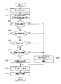
- cranking torque control process The cranking torque control process executed by the cranking torque control device 100 when the engine 11 is started (for example, when shifting from the EV traveling mode to the HV traveling mode) will be described with reference to the flowchart of FIG. To do.
- This cranking torque control process is repeatedly executed at predetermined time intervals (for example, every several milliseconds (milliseconds)) when the engine 11 is started.
- step S101 the ECU 22 as a part of the cranking torque control device 100 acquires the voltage across the terminals of the battery 21 detected by the voltage sensor 23 (step S101).
- the ECU 22 calculates input / output powers Win and Wout based on the state of the battery 21 (step S102). Specifically, for example, the ECU 22 is based on the remaining capacity (State of Charge: SOC) of the battery 21 specified by the acquired inter-terminal voltage of the battery 21, the temperature of the battery 21 detected by the temperature sensor 25, and the like. The input / output powers Win and Wout are calculated. The remaining capacity of the battery 21 may be specified by integrating the current value detected by the current sensor 24.
- SOC State of Charge
- the ECU 22 determines whether or not the voltage between the terminals of the battery 21 detected by the voltage sensor 23 is lower than the lower limit voltage related to the battery 21 (step S103). When it is determined that the voltage between the terminals of the battery 21 is equal to or higher than the lower limit voltage (step S103: No), the ECU 22 calculates the input / output allowable limits Winf and Woutf based on the power deviation (step S110). Since various known modes can be applied to the calculation method of the input / output allowable limits Winf and Woutf, details thereof are omitted for the purpose of preventing the explanation from becoming complicated.
- the ECU 22 calculates the upper limit output torque and the lower limit output torque based on the calculated input / output allowable limits Winf and Woutf (step S108), and calculates the target torque within the range of the upper limit output torque and the lower limit output torque. (Step S109).
- step S103 when it is determined that the voltage between the terminals of the battery 21 is lower than the lower limit voltage (step S103: Yes), the ECU 22 temporarily causes the lower limit voltage crack of the battery 21 to be caused by resonance of the engine 11. It is determined whether or not the lower limit voltage is cracked. Specifically, the ECU 22 executes the determination process of steps S104 to S106 described below. Note that the processing of steps S104 to S106 is not limited to the order described in FIG. 2, and may be executed from any processing.
- the ECU 22 determines whether or not the lower limit voltage crack of the battery 21 is caused by fluctuations in the rotational speed of the engine 11 (step S104). Specifically, for example, the ECU 22 determines that the lower limit voltage crack of the battery 21 is based on a change in the rotational speed of the engine 11 within a predetermined period in the vicinity of the time when the inter-terminal voltage of the battery 21 is determined to be lower than the lower limit voltage. It is determined whether or not it is caused by fluctuations in the rotational speed of the engine 11.
- step S104 determines that the rotational speed of the engine 11 is the rotational speed corresponding to the resonance band. It is determined whether or not there is (step S105).
- step S105 determines that the rotational speed of the engine 11 is a rotational speed corresponding to the resonance band.
- step S106 determines whether or not this period coincides with the period of the explosion primary component of the engine 11.
- step S106 determines that the lower limit voltage crack of the battery 21 is a temporary lower limit voltage crack caused by the resonance of the engine 11. Then, the ECU 22 does not calculate the input / output allowable limits Winf and Woutf based on the power deviation (that is, without executing the processing in step S110 described above), and outputs the output power Wout calculated in the processing in step S102 described above. Is maintained (step S107).
- the ECU 22 calculates an upper limit output torque and a lower limit output torque based on the input / output powers Win and Wout (step S108), and calculates a target torque (step S109).
- Step S104 to S106 When the result of any of the determination processes of Steps S104 to S106 described above is “No” (that is, (i) the lower limit voltage crack of the battery 21 is not caused by the rotational speed fluctuation of the engine 11 ( ii) The rotation speed of the engine 11 is not the rotation speed corresponding to the resonance band, or (iii) the lower limit voltage crack of the battery 21 is not intermittent, or the rotation speed fluctuation cycle of the engine 11 is the primary explosion of the engine 11 When it is determined that the cycle of the component does not match), the ECU 22 determines that the lower limit voltage crack of the battery 21 is not temporary. And ECU22 performs the process of step S110 mentioned above from a viewpoint of battery 21 protection.
- FIGS. 3 and 4 A second embodiment of the cranking torque control device of the present invention will be described with reference to FIGS.
- the second embodiment is the same as the configuration of the first embodiment except that the cranking torque control process to be executed is partially different. Accordingly, the description of the second embodiment that is the same as that of the first embodiment is omitted, and common portions in the drawings are denoted by the same reference numerals, and only the points that are basically different are shown in FIGS. 3 and 4. The description will be given with reference.
- cranking torque control process The cranking torque control process executed by the cranking torque control apparatus 100 according to the present embodiment will be described with reference to the flowchart of FIG.
- step S ⁇ b> 103: No when it is determined that the voltage between the terminals of the battery 21 is equal to or higher than the lower limit voltage (step S ⁇ b> 103: No), the ECU 22 causes the lower limit voltage crack of the battery 21 to be temporarily caused by the initial explosion of the engine 11. It is determined whether or not the lower limit voltage is cracked. Specifically, the ECU 22 executes the determination processes of steps S201 and S202 below. Note that the processes in steps S201 and S202 are not limited to the order described in FIG. 3, and may be executed from either process.
- step S201 determines whether the lower limit voltage crack of the battery 21 is caused by the increase in the rotational speed of the engine 11.
- step S201: Yes the ECU 22 determines whether or not the engine 11 has undergone an initial explosion (step S201). S202).
- step S202 determines the lower limit voltage of the battery 21. It is determined that the crack is a temporary lower limit voltage crack caused by the first explosion of the engine 11. Then, the ECU 22 calculates the output allowable limit Wout_fire in consideration of the increase in the rotational speed of the engine 11 (step S203).
- FIG. 4 is a conceptual diagram showing an example of temporal fluctuations in engine speed and battery voltage.
- the ECU 22 calculates the output allowable limit Wout_fire by subtracting the power consumed excessively due to the first explosion of the engine 11 from the output power Wout calculated in the process of step S102.
- the ECU 22 calculates a target torque according to the calculated output allowable limit Wout_fire (step S109). Specifically, for example, the ECU 22 calculates a target torque by the following formula.
- Target torque output allowable limit Wout_fire ⁇ (estimated rotation speed ⁇ circumference ratio ⁇ 2)
- the “predicted arrival rotation speed” means the rotation speed of the engine 11 predicted to reach after a predetermined time (see time t3 in the upper part of FIG. 4).
- step S201 and step S202 When the result of any of the determination processes in step S201 and step S202 described above is “No” (that is, (i) the lower limit voltage crack of the battery 21 is not caused by the increase in the rotational speed of the engine 11, Or (ii) When it is determined that the engine 11 does not have the first explosion), the ECU 22 determines that the lower limit voltage crack of the battery 21 is not temporary. And ECU22 performs the process of step S110 mentioned above from a viewpoint of battery 21 protection.
- the present invention is not limited to the above-described embodiment, and can be appropriately changed without departing from the gist or concept of the invention that can be read from the claims and the entire specification, and cranking torque control with such a change is possible.
- the apparatus is also included in the technical scope of the present invention.
Landscapes
- Engineering & Computer Science (AREA)
- Transportation (AREA)
- Mechanical Engineering (AREA)
- Chemical & Material Sciences (AREA)
- Combustion & Propulsion (AREA)
- Automation & Control Theory (AREA)
- Electric Propulsion And Braking For Vehicles (AREA)
- Hybrid Electric Vehicles (AREA)
Abstract
Description
(車両の構成)
第1実施形態に係るハイブリッド車両の構成について、図1を参照して説明する。図1は、本実施形態に係るハイブリッド車両の構成を示す概略図である。尚、図1では、本発明と直接関連のある部材のみを示し、その他の部材については適宜省略している。
以上のように構成されたハイブリッド車両1に搭載されるクランキングトルク制御装置100は、モータ・ジェネレータMG1がエンジン11をクランキングする際に、電力偏差に応じてバッテリ21から出力される電力の制限値である出力制限値を設定可能であると共に、エンジン11の共振に起因してバッテリ21の電圧が、該バッテリ21に係る下限電圧より低くなったことを条件に、出力制限値の設定を停止するECU22を備えて構成されている。
エンジン11が始動される際(例えば、EV走行モードからHV走行モードへ移行する際等)に、クランキングトルク制御装置100が実行するクランキングトルク制御処理について、図2のフローチャートを参照して説明する。このクランキングトルク制御処理は、エンジン11が始動される際に、所定時間毎(例えば、数msec(ミリ秒)毎)に繰り返し実行される。
本発明のクランキングトルク制御装置に係る第2実施形態を、図3及び図4を参照して説明する。第2実施形態では、実行されるクランキングトルク制御処理が一部異なっている以外は、第1実施形態の構成と同様である。よって、第2実施形態について、第1実施形態と重複する説明を省略すると共に、図面上における共通箇所には同一符号を付して示し、基本的に異なる点についてのみ、図3及び図4を参照して説明する。
本実施形態に係るクランキングトルク制御装置100が実行するクランキングトルク制御処理について、図3のフローチャートを参照して説明する。
目標トルク=出力許容制限Wout_fire÷(到達予測回転数×円周率×2)
ここで、「到達予測回転数」とは、所定時間後に到達すると予測されるエンジン11の回転数(図4上段の時刻t3参照)を意味する。
Claims (2)
- エンジンと、前記エンジンに連結されると共に、前記エンジンをクランキング可能なモータと、前記モータに電力を供給可能なバッテリと、を備えるハイブリッド車両に搭載され、
前記モータが前記エンジンをクランキングする際に、電力偏差に応じて前記バッテリから出力される電力の制限値である出力制限値を設定可能な設定手段と、
前記エンジンの共振に起因して、前記バッテリの電圧が該バッテリに係る下限電圧より低くなったことを条件に、前記出力制限値を設定しないように前記設定手段を制御する制御手段と、
を備えることを特徴とするクランキングトルク制御装置。 - エンジンと、前記エンジンに連結されると共に、前記エンジンをクランキング可能なモータと、前記モータに電力を供給可能なバッテリと、を備えるハイブリッド車両に搭載され、
前記モータが前記エンジンをクランキングする際に、電力偏差に応じて前記バッテリから出力される電力の制限値である出力制限値を設定可能な設定手段と、
前記エンジンの初爆に起因して、前記バッテリの電圧が該バッテリに係る下限電圧より低くなったことを条件に、前記出力制限値を設定しないように前記設定手段を制御する制御手段と、
を備えることを特徴とするクランキングトルク制御装置。
Priority Applications (4)
| Application Number | Priority Date | Filing Date | Title |
|---|---|---|---|
| JP2012512150A JPWO2012157089A1 (ja) | 2011-05-18 | 2011-05-18 | クランキングトルク制御装置 |
| CN2011800040145A CN102892654A (zh) | 2011-05-18 | 2011-05-18 | 启动转矩控制装置 |
| PCT/JP2011/061409 WO2012157089A1 (ja) | 2011-05-18 | 2011-05-18 | クランキングトルク制御装置 |
| US13/390,629 US8565956B2 (en) | 2011-05-18 | 2011-05-18 | Cranking torque control apparatus |
Applications Claiming Priority (1)
| Application Number | Priority Date | Filing Date | Title |
|---|---|---|---|
| PCT/JP2011/061409 WO2012157089A1 (ja) | 2011-05-18 | 2011-05-18 | クランキングトルク制御装置 |
Publications (1)
| Publication Number | Publication Date |
|---|---|
| WO2012157089A1 true WO2012157089A1 (ja) | 2012-11-22 |
Family
ID=47175542
Family Applications (1)
| Application Number | Title | Priority Date | Filing Date |
|---|---|---|---|
| PCT/JP2011/061409 Ceased WO2012157089A1 (ja) | 2011-05-18 | 2011-05-18 | クランキングトルク制御装置 |
Country Status (4)
| Country | Link |
|---|---|
| US (1) | US8565956B2 (ja) |
| JP (1) | JPWO2012157089A1 (ja) |
| CN (1) | CN102892654A (ja) |
| WO (1) | WO2012157089A1 (ja) |
Families Citing this family (2)
| Publication number | Priority date | Publication date | Assignee | Title |
|---|---|---|---|---|
| US20140014054A1 (en) * | 2012-07-10 | 2014-01-16 | Caterpillar Inc. | Engine Starting Strategy to Avoid Resonant Frequency |
| FR3132685B1 (fr) * | 2022-02-15 | 2024-11-01 | Vitesco Technologies | Procédé d’optimisation de la consommation en énergie d’un véhicule automobile |
Citations (3)
| Publication number | Priority date | Publication date | Assignee | Title |
|---|---|---|---|---|
| JP2006094691A (ja) * | 2004-08-25 | 2006-04-06 | Toyota Motor Corp | 動力出力装置およびこれを搭載する自動車並びに動力出力装置の制御方法 |
| JP2009190525A (ja) * | 2008-02-13 | 2009-08-27 | Nissan Motor Co Ltd | ハイブリッド車両のエンジン始動装置 |
| JP2011051480A (ja) * | 2009-09-02 | 2011-03-17 | Toyota Motor Corp | 内燃機関装置およびハイブリッド車並びに内燃機関の始動方法 |
Family Cites Families (16)
| Publication number | Priority date | Publication date | Assignee | Title |
|---|---|---|---|---|
| JP3379439B2 (ja) * | 1997-09-17 | 2003-02-24 | トヨタ自動車株式会社 | 内燃機関の始動制御装置 |
| JP4123501B2 (ja) | 1999-08-09 | 2008-07-23 | マツダ株式会社 | ハイブリッド車両の駆動装置 |
| US7032581B2 (en) * | 2004-03-19 | 2006-04-25 | Ford Global Technologies, Llc | Engine air-fuel control for an engine with valves that may be deactivated |
| JP4086010B2 (ja) * | 2004-05-11 | 2008-05-14 | トヨタ自動車株式会社 | 動力出力装置およびこれを搭載する自動車並びに動力出力装置の制御方法 |
| DE102005034794A1 (de) * | 2004-07-23 | 2006-02-23 | Ford Global Technologies, LLC, Dearborn | Verfahren zum Dämpfen von Vibrationen im Antriebsstrang eines hybridelektrischen Fahrzeugs |
| JP4207891B2 (ja) | 2004-12-27 | 2009-01-14 | トヨタ自動車株式会社 | 内燃機関の始動装置およびこれを搭載する自動車並びに始動装置の制御方法 |
| JP2007168637A (ja) | 2005-12-22 | 2007-07-05 | Toyota Motor Corp | 動力出力装置およびこれを搭載する車両並びに動力出力装置の制御方法 |
| US7722498B2 (en) * | 2006-06-21 | 2010-05-25 | Denso Corporation | Control device and method for hybrid electric vehicle |
| JP4229175B2 (ja) | 2006-11-22 | 2009-02-25 | トヨタ自動車株式会社 | 動力出力装置、それを備えた自動車、および動力出力装置の制御方法 |
| JP4241837B2 (ja) * | 2007-01-15 | 2009-03-18 | トヨタ自動車株式会社 | 車両およびその制御方法 |
| JP4453746B2 (ja) | 2007-11-21 | 2010-04-21 | トヨタ自動車株式会社 | 動力出力装置およびその制御方法並びに車両 |
| JP4992728B2 (ja) | 2008-01-10 | 2012-08-08 | トヨタ自動車株式会社 | 電源装置およびその放電制御方法 |
| JP4535135B2 (ja) * | 2008-01-17 | 2010-09-01 | トヨタ自動車株式会社 | 始動制御装置 |
| JP2009292179A (ja) | 2008-06-02 | 2009-12-17 | Toyota Motor Corp | ハイブリッド自動車およびその制御方法 |
| US8509979B2 (en) * | 2009-05-27 | 2013-08-13 | Toyota Jidosha Kabushiki Kaisha | Control apparatus for hybrid vehicle |
| US20130017926A1 (en) * | 2011-05-18 | 2013-01-17 | Toyota Jidosha Kabushiki Kaisha | Cranking torque control apparatus |
-
2011
- 2011-05-18 US US13/390,629 patent/US8565956B2/en not_active Expired - Fee Related
- 2011-05-18 WO PCT/JP2011/061409 patent/WO2012157089A1/ja not_active Ceased
- 2011-05-18 CN CN2011800040145A patent/CN102892654A/zh active Pending
- 2011-05-18 JP JP2012512150A patent/JPWO2012157089A1/ja active Pending
Patent Citations (3)
| Publication number | Priority date | Publication date | Assignee | Title |
|---|---|---|---|---|
| JP2006094691A (ja) * | 2004-08-25 | 2006-04-06 | Toyota Motor Corp | 動力出力装置およびこれを搭載する自動車並びに動力出力装置の制御方法 |
| JP2009190525A (ja) * | 2008-02-13 | 2009-08-27 | Nissan Motor Co Ltd | ハイブリッド車両のエンジン始動装置 |
| JP2011051480A (ja) * | 2009-09-02 | 2011-03-17 | Toyota Motor Corp | 内燃機関装置およびハイブリッド車並びに内燃機関の始動方法 |
Also Published As
| Publication number | Publication date |
|---|---|
| US8565956B2 (en) | 2013-10-22 |
| JPWO2012157089A1 (ja) | 2014-07-31 |
| US20120296503A1 (en) | 2012-11-22 |
| CN102892654A (zh) | 2013-01-23 |
Similar Documents
| Publication | Publication Date | Title |
|---|---|---|
| CN101678827B (zh) | 车辆及其控制方法 | |
| US20150258911A1 (en) | Hybrid vehicle | |
| JP5741153B2 (ja) | 充電制御装置 | |
| JP5273305B2 (ja) | クランキングトルク制御装置 | |
| JP2009274677A (ja) | ハイブリッド車両の制御装置 | |
| JPWO2012111123A1 (ja) | ハイブリッド車両の制御装置 | |
| JP2013154720A (ja) | ハイブリッド車両 | |
| JP5459144B2 (ja) | ハイブリッド車 | |
| JP4876054B2 (ja) | 動力出力装置、それを備えた車両および動力出力装置の制御方法 | |
| JP2010163061A (ja) | 動力出力装置、それを備えた車両および動力出力装置の制御方法 | |
| JP2009292179A (ja) | ハイブリッド自動車およびその制御方法 | |
| JP2010188937A (ja) | ハイブリッド車両 | |
| CN105705367B (zh) | 混合动力车辆、用于混合动力车辆的控制方法及用于混合动力车辆的控制器 | |
| JP2009248586A (ja) | ハイブリッド制御装置 | |
| JP2009107554A (ja) | 動力出力装置、それを備えた車両および動力出力装置の制御方法 | |
| EP2957473B1 (en) | Hybrid vehicle | |
| JP5700362B2 (ja) | ハイブリッド車両 | |
| JP5331065B2 (ja) | 車載内燃機関制御装置 | |
| JPWO2012140762A1 (ja) | ハイブリッド車両およびそれに搭載される蓄電装置の出力制御方法 | |
| WO2012157089A1 (ja) | クランキングトルク制御装置 | |
| JP2017140869A (ja) | バッテリシステム | |
| JP2013126825A (ja) | 車両用制御装置 | |
| JP4687476B2 (ja) | 動力出力装置およびこれを搭載する自動車並びにハイブリッド車,動力出力装置の制御方法 | |
| JP2024010803A (ja) | ハイブリッド車両の制御装置および方法 | |
| WO2024195851A1 (ja) | 電動車両の制御システム |
Legal Events
| Date | Code | Title | Description |
|---|---|---|---|
| WWE | Wipo information: entry into national phase |
Ref document number: 201180004014.5 Country of ref document: CN |
|
| WWE | Wipo information: entry into national phase |
Ref document number: 13390629 Country of ref document: US |
|
| ENP | Entry into the national phase |
Ref document number: 2012512150 Country of ref document: JP Kind code of ref document: A |
|
| 121 | Ep: the epo has been informed by wipo that ep was designated in this application |
Ref document number: 11865567 Country of ref document: EP Kind code of ref document: A1 |
|
| WWE | Wipo information: entry into national phase |
Ref document number: 1120111052510 Country of ref document: DE Ref document number: 112011105251 Country of ref document: DE |
|
| 122 | Ep: pct application non-entry in european phase |
Ref document number: 11865567 Country of ref document: EP Kind code of ref document: A1 |