WO2012153564A1 - パネル材の溶接接合方法及び接合パネル材 - Google Patents
パネル材の溶接接合方法及び接合パネル材 Download PDFInfo
- Publication number
- WO2012153564A1 WO2012153564A1 PCT/JP2012/055418 JP2012055418W WO2012153564A1 WO 2012153564 A1 WO2012153564 A1 WO 2012153564A1 JP 2012055418 W JP2012055418 W JP 2012055418W WO 2012153564 A1 WO2012153564 A1 WO 2012153564A1
- Authority
- WO
- WIPO (PCT)
- Prior art keywords
- panel
- welding
- joining
- edge
- panel material
- Prior art date
- Legal status (The legal status is an assumption and is not a legal conclusion. Google has not performed a legal analysis and makes no representation as to the accuracy of the status listed.)
- Ceased
Links
Images


Classifications
-
- B—PERFORMING OPERATIONS; TRANSPORTING
- B60—VEHICLES IN GENERAL
- B60J—WINDOWS, WINDSCREENS, NON-FIXED ROOFS, DOORS, OR SIMILAR DEVICES FOR VEHICLES; REMOVABLE EXTERNAL PROTECTIVE COVERINGS SPECIALLY ADAPTED FOR VEHICLES
- B60J5/00—Doors
- B60J5/10—Doors arranged at the vehicle rear
- B60J5/101—Doors arranged at the vehicle rear for non-load transporting vehicles, i.e. family cars including vans
- B60J5/107—Doors arranged at the vehicle rear for non-load transporting vehicles, i.e. family cars including vans constructional details, e.g. about door frame, panels, materials used, reinforcements
-
- B—PERFORMING OPERATIONS; TRANSPORTING
- B23—MACHINE TOOLS; METAL-WORKING NOT OTHERWISE PROVIDED FOR
- B23K—SOLDERING OR UNSOLDERING; WELDING; CLADDING OR PLATING BY SOLDERING OR WELDING; CUTTING BY APPLYING HEAT LOCALLY, e.g. FLAME CUTTING; WORKING BY LASER BEAM
- B23K26/00—Working by laser beam, e.g. welding, cutting or boring
- B23K26/20—Bonding
- B23K26/21—Bonding by welding
- B23K26/24—Seam welding
- B23K26/26—Seam welding of rectilinear seams
-
- B—PERFORMING OPERATIONS; TRANSPORTING
- B23—MACHINE TOOLS; METAL-WORKING NOT OTHERWISE PROVIDED FOR
- B23K—SOLDERING OR UNSOLDERING; WELDING; CLADDING OR PLATING BY SOLDERING OR WELDING; CUTTING BY APPLYING HEAT LOCALLY, e.g. FLAME CUTTING; WORKING BY LASER BEAM
- B23K31/00—Processes relevant to this subclass, specially adapted for particular articles or purposes, but not covered by any single one of main groups B23K1/00 - B23K28/00
- B23K31/003—Processes relevant to this subclass, specially adapted for particular articles or purposes, but not covered by any single one of main groups B23K1/00 - B23K28/00 relating to controlling of welding distortion
-
- B—PERFORMING OPERATIONS; TRANSPORTING
- B23—MACHINE TOOLS; METAL-WORKING NOT OTHERWISE PROVIDED FOR
- B23K—SOLDERING OR UNSOLDERING; WELDING; CLADDING OR PLATING BY SOLDERING OR WELDING; CUTTING BY APPLYING HEAT LOCALLY, e.g. FLAME CUTTING; WORKING BY LASER BEAM
- B23K9/00—Arc welding or cutting
- B23K9/02—Seam welding; Backing means; Inserts
- B23K9/025—Seam welding; Backing means; Inserts for rectilinear seams
-
- B—PERFORMING OPERATIONS; TRANSPORTING
- B23—MACHINE TOOLS; METAL-WORKING NOT OTHERWISE PROVIDED FOR
- B23K—SOLDERING OR UNSOLDERING; WELDING; CLADDING OR PLATING BY SOLDERING OR WELDING; CUTTING BY APPLYING HEAT LOCALLY, e.g. FLAME CUTTING; WORKING BY LASER BEAM
- B23K2101/00—Articles made by soldering, welding or cutting
- B23K2101/006—Vehicles
-
- B—PERFORMING OPERATIONS; TRANSPORTING
- B23—MACHINE TOOLS; METAL-WORKING NOT OTHERWISE PROVIDED FOR
- B23K—SOLDERING OR UNSOLDERING; WELDING; CLADDING OR PLATING BY SOLDERING OR WELDING; CUTTING BY APPLYING HEAT LOCALLY, e.g. FLAME CUTTING; WORKING BY LASER BEAM
- B23K2101/00—Articles made by soldering, welding or cutting
- B23K2101/18—Sheet panels
Definitions
- the present invention relates to a method for welding and joining panel materials in which edges of a plurality of panel materials are butted against each other and welded together.
- Patent Document 1 what is described in the following Patent Document 1 is known as a material that joins and welds the edge portions of panel materials. This is applied to the back door inner panel that constitutes the back door of an automobile, and the edge of the relatively thick upper portion and the edge of the relatively thin lower portion are abutted against each other. Welded in a state.
- This invention aims at suppressing the deformation
- One aspect of the present invention is the welding direction at the time of welding and joining the panel material in the central part and one of the two panel parts, and welding between the panel material in the central part and the other panel material in the two side parts.
- This is a method for welding and joining panel materials in which the welding directions at the time of joining are opposite to each other.
- the other aspect of this invention is the joining panel material manufactured by the welding joining method of the said panel material.
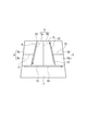
- FIG. 1 is a figure which shows the panel joining method which concerns on embodiment of this invention
- (a) is a front view which shows the panel joining method which concerns on one Embodiment
- (b) is a welding direction with respect to (a).
- It is a front view which shows the panel joining method which concerns on the modification made into the reverse direction.
- FIG. 2 is a front view showing a modification in which the center panel and the side panel material in FIG.
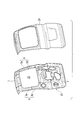
- FIG. 3 shows an example in which the panel material joining method is applied to a back door of an automobile.
- (A) is a simplified front view
- (b) is a front view of an actual back door
- (c) is ( It is GG sectional drawing of b).
- FIG. 4 is a perspective view of a back door outer panel and a back door inner panel constituting the back door.
- the edge of one central panel member 1 located at the central portion in the left-right direction and the left and right sides of the central panel member 1
- the edge portions of the two side panel materials 3 and 5 positioned and the edge portion of the lower panel material 7 positioned below the panel materials 1, 3 and 5 are welded to each other.
- welding joining for example, laser welding is performed, but it is not limited to laser welding.
- the center panel member 1 has the side edge of the side panel member 3 (second panel member) abutted against one side edge on the left side in FIG. 1A, and the joined edge 9 is joined by welding. Further, the side edge of the side panel material 5 (third panel material) is abutted against the other side edge on the right side in FIG. 1A of the center panel material 1, and the abutted joining edge 11 is welded. Further, the lower panel material 7 (fourth panel material) is butted against the lower edge in FIG. 1A of the three panel materials 1, 3 and 5 joined to each other, and the joined edge 13 is abutted. Welded together. That is, this lower panel material 7 constitutes another panel material that is welded and joined to one end of each of the three panel materials.
- the welding joint operation at the joint edge 9 between the central panel member 1 and the one side panel member 3 is the first from the upper part toward the lower lower panel member 7 in FIG. 1 in the welding direction S1.
- the welding operation at the joint edge 11 between the central panel member 1 and the other side panel member 5 is the second welding from the lower part toward the opposite side of the upper lower panel member 7 in FIG. The process is performed in the direction opposite to the direction S2, that is, the first welding direction S1.
- the second half of welding in which the vicinity of the end A located on the lower side in FIG. 1A is welded is the vicinity of the start B located on the upper side in FIG.
- the deformation due to heat generated during welding is greater in the latter half of the weld including the vicinity of the end A than in the first half of the weld including the vicinity of the start B.
- the welding operation at the joint edge 13 between the three panel materials 1, 3, 5 and the lower panel material 7 performed after the three panel materials 1, 3, 5 are joined is performed by the lower panel material 7 Start from the side of the joining edge 9 whose side is the end A of welding. And this welding joining work is performed in the 3rd welding direction S3 which goes to the joining edge 11 side from the joining edge 9 side.
- the welding end E of the joint edge 13 is close to the start end D of the joint edge 11 and far from the end A of the joint edge 9 when viewed along the joint edge 13. That is, the welding operation at the joint edge 13 is performed from the side of the joint edges 9 and 11 that is larger in thermal deformation during welding toward the smaller side.
- the welding direction at the joint edge 13 is the direction opposite to the third welding direction S3 (the direction from right to left in FIG. 1A) and the end of welding is on the joint edge 9 side.
- the deformation of the entire four panel members after joining can be suppressed to be small.
- FIG. 1 (b) is a modification of the embodiment shown in FIG. 1 (a).
- each of the joint edges 9, 11, 13 at three locations is different from the embodiment of FIG. 1 (a).
- the welding direction is the reverse direction.
- the welding joint operation at the joint edge 9 between the central panel member 1 and the side panel member 3 is performed in the first welding direction S11 from the lower panel member 7 side toward the upper part in FIG. .
- the welding operation at the joint edge 11 between the central panel member 1 and the side panel member 5 is directed to the second welding direction S21 from the upper part toward the lower panel member 7 in FIG. That is, it is performed in the direction opposite to the first welding direction S11.
- the end A1 where the thermal deformation at the joint edge 9 becomes larger and the end C1 where the thermal deformation at the joint edge 11 becomes larger are positioned further apart. Deformation due to heat of the entire three panel members after joining can be suppressed.
- the welding operation at the joint edge 13 between the three panel materials 1, 3, 5 and the lower panel material 7 performed after the three panel materials 1, 3, 5 are joined is performed by the lower panel material 7 It starts from the side of the joining edge 11 whose side is the terminal end C1 of welding. And this welding joining work is performed in the 3rd welding direction S31 which goes to the joining edge 9 side from the joining edge 11 side opposite to 3rd welding direction S3 in Fig.1 (a).
- the end E1 of the joining edge 13 where the thermal deformation is increased is larger than the end C1 of the joining edge 11 where the thermal deformation is increased when viewed along the joining edge 13. It becomes a distant position and can suppress the deformation
- either of the joining order of the joining edge 9 and the joining edge 11 may be performed first.
- the center panel material 1 is made into a trapezoid shape, and the shape of the whole four panel materials after joining is also made into a trapezoid shape, these may be made into square shape or rectangular shape.
- the four panel members 1, 3, 5, and 7 described above may have the same thickness or may be different from each other.
- the center panel member 1 and the side panel members 3 and 5 are each divided into two divided panel members 1a and 1b. What was divided
- segmented into 3a, 3b, 5a, 5b may be comprised by welding.
- the center panel member 1 and the side panel members 3, 5 are manufactured.
- the welding operation as shown in FIG. 1 is performed. Thereby, the press part using this joining panel material which suppressed the thermal deformation at the time of welding can change a rigidity and mass suitably according to a part, and it becomes possible to manufacture a product according to a use situation.
- FIG. 3 shows an example in which the method for welding and joining panel materials according to the present embodiment is applied to a back door of an automobile.
- the back door includes a back door outer panel 21 located outside the vehicle body and a back door inner panel 23 coupled to the vehicle body inside.
- the method for welding and joining panel materials according to the present embodiment is applied to the back door inner panel 23.
- FIG. 3A the plurality of panel materials constituting the back door inner panel 23 are illustrated in a simplified manner as in FIG. 1 and FIG. 3, the same code
- the back door inner panel 23 includes an edge portion of one central panel member 1 located at the central portion in the left-right direction, and two side panel members 3, 5 located on the left and right sides of the central panel member 1. And the edge of the lower panel member 7 located below each of the panel members 1, 3 and 5 are welded together.
- the two side panel materials 3 and 5 are welded and joined in advance into two divided panel materials 3a, 3b, 5a, and 5b in the same manner as shown in FIG. Moreover, about the welding direction in each joint edge 9,11,13 similarly to what was shown to Fig.1 (a) and FIG. 2, 1st welding direction S1, 2nd welding direction S2, and 3rd, respectively.
- the welding direction S3 is used to suppress thermal deformation of the entire panel material after joining.
- the welding direction in each joining edge 9,11,13 is 1st welding direction S11, 2nd welding direction S21, and 3rd contrary to Fig.1 (a) like FIG.1 (b).
- the welding direction S31 may be used.
- an opening 25 into which the window glass is fitted is formed on the upper part of the actual back door inner panel 23.
- the opening 25 is formed over the upper and lower divided panel members 3a, 3b and 5a, 5b of the side panel members 3 and 5. That is, the divided portions of the upper and lower divided panel members 3a, 3b and 5a, 5b (corresponding to the joint portions 17 and 19 in FIG. 3A) are at positions corresponding to the openings 25.
- the panel materials used for the back door inner panel 23 are changed in thickness from each other as follows. That is, the divided panel members 3a and 5a are the thickest, the center panel member 1 and the lower panel member 7 are the thinnest, and the divided panel members 3b and 5b have an intermediate thickness.
- the thickness relationship of the plate thickness is as follows. “Thickness of split panel members 3a, 5a”> “Thickness of split panel members 3b, 5b”> “Thickness of center panel member 1 and lower panel member 7”
- the plate of the back door inner panel 23 The thickness can be gradually changed from the upper divided panel materials 3a and 5a having high rigidity to the thinnest central panel material 1 and lower panel material 7, and the necessary cross-sectional rigidity can be secured at the lower part of the window frame skeleton. .
- the center panel material 1 Since the center panel material 1 is supported by the vehicle body via the divided panel materials 3a and 5a on the upper sides of the side panel materials 3 and 5 located on both sides thereof, the center panel material 1 can be made the thinnest together with the lower panel material 7. it can. Thereby, the back door inner panel 23 can be reduced in weight, and the weight reduction of the whole back door can be achieved.
- the panel material welding and joining method includes at least three panel materials 1 and 3 that are located at the center portion and at two sides located between both sides sandwiching the center portion.
- , 5 is a method for welding and joining panel materials that are welded together in a state where the edges of each other face each other.
- the weld joint between the edge of the panel member 1 at the center and the edge of one panel member 3 (or 5) of the both sides is made along the joint edge 9 (or 11).
- S1 or S21
- the welding joint of the edge part of the panel material 1 of a center part and the edge part of the other panel material 5 (or 3) of both sides is made into 1st along each joint edge 11 (or 9). This is performed in the second welding direction S2 (or S11) which is opposite to the welding direction S1 (or S21).
- a line segment connecting the weld joint start end B at the joint edge 9 and the weld joint start end D at the joint edge 11, and the weld joint end A and the joint at the joint edge 9 are joined.
- Line segments connecting the start end C of the weld joint at the edge 11 intersect each other, and the start end D is closer to the end A than the start end B, and the end C is closer to the start B than the end A.
- a line segment connecting the weld joint start end D1 at the joint edge 11 and the weld joint start end B1 at the joint edge 9 and the weld joint end C1 at the joint edge 11 are joined.
- Line segments connecting the weld joint start end B1 at the edge 9 intersect each other, and the start end B1 is closer to the end C1 than the start end D1, and the end A1 is closer to the start end D1 than the end C1.
- the end A (or A1) and the end C (or C1) of welding which tend to be greatly deformed by heat generated during welding, are between the joining edges 9 and 11.
- the position will be further away. Therefore, the entire three panel members after joining are compared to the case in which the welding ends are the same direction at the joining edge 9 and the joining edge 11 and the welding ends are closer to each other between the joining edges 9 and 11. It is possible to suppress deformation due to heat.
- the welding joining method of the present embodiment is the other one panel material at the edge of one end of each of the three panel materials 1, 3, and 5.
- the edge portions of 7 are abutted and welded together, the panel materials 3 and 5 on both sides are joined to the end A side of the welding performed in one of the first welding direction S1 and the second welding direction S2.
- Welding is performed from a certain panel material 3 side toward the panel material 5 side on the start end D side of welding performed in either one of the first welding direction S1 and the second welding direction S2.
- the edge of one panel material 7 is butted against the edge of one end of each of the three panel materials 1, 3 and 5 and welded.
- the end E (or E1) of welding between the three panel members 1, 3, 5 and the other one panel member 7 is viewed along the joint edge 13, the deformation due to heat is small. It is close to the starting end D of the joining edge 11 (or the starting end B1 of the joining edge 9) and is far from the end A of the joining edge 9 (or the end C1 of the joining edge 11) that is greatly deformed by heat. That is, the welding operation at the joint edge 13 is performed from the side with the larger thermal deformation during welding at the joint edges 9 and 11 toward the smaller side.
- the two panel members 3 and 5 positioned on both sides are thicker than the one panel member 1 and the other panel member 7 positioned at the center. May be thickened. Thereby, for example, even when two panel members 3 and 5 located on both sides are applied as constituent members of the rotation shaft support portion of the door member, the weight of the door member is secured while ensuring the rigidity. can do.
- the two panel materials 3 and 5 located in both sides are divided
- 3b, 5a, 5b may be joined to each other.
- the divided panel members 3a, 3b, 5a, 5b are opposed to each other with one panel member 1 located in the center therebetween, and one side 3b located on the other panel member 7 side.
- 5b may be made thinner than the thickness of the other side 3a, 5a facing each other with one panel member 1 located in the center interposed therebetween.
- the cross-sectional rigidity of the window frame skeleton is concerned. Can be secured.
- the welding directions along the joint edges are opposite to each other.
Landscapes
- Engineering & Computer Science (AREA)
- Mechanical Engineering (AREA)
- Physics & Mathematics (AREA)
- Plasma & Fusion (AREA)
- Optics & Photonics (AREA)
- Laser Beam Processing (AREA)
Abstract
中央部のパネル材(1)と両側部のうちの一方のパネル材(3)との溶接接合時の溶接方向(S1)と、中央部のパネル材(1)と両側部のうちの他方のパネル材(5)との溶接接合時の溶接方向(S2)とを、互いに逆方向とするパネル材の溶接接合方法。
Description
本発明は、複数のパネル材の縁部を互いに突き合わせて溶接接合するパネル材の溶接接合方法及び接合パネル材に関する。
パネル材相互の縁部を突き合わせて溶接接合するものとして、例えば下記特許文献1に記載されたものが知られている。これは自動車のバックドアを構成するバックドアインナパネルに適用するもので、相対的に板厚の厚い上側部分の縁部と相対的に板厚の薄い下側部分の縁部とを互いに突き合わせた状態で溶接接合している。
ところで、このように複数のパネル材の縁部を互いに突き合わせて溶接接合する際には、突き合わせ部分の接合縁に沿って溶接していくことになるが、その際発生する熱による変形は、熱が徐々に蓄積されていく接合後半側のほうが接合前半よりも大きくなる傾向にある。このため、接合パネル材の熱による変形を抑えるために溶接方向について考慮する必要がある。
本発明は、パネル材相互の縁部を突き合わせて溶接接合する際のパネル材の変形を抑制することを目的としている。
本発明の一態様は、中央部のパネル材と両側部のうちの一方のパネル材との溶接接合時の溶接方向と、中央部のパネル材と両側部のうちの他方のパネル材との溶接接合時の溶接方向とを、互いに逆方向とするパネル材の溶接接合方法である。
また、本発明の他の態様は、上記パネル材の溶接接合方法によって製造した接合パネル材である。
以下、本発明の実施の形態を図面に基づき説明する。
図1(a)に示す本発明の一実施形態では、左右方向の中央部に位置する1枚の中央パネル材1(第1パネル材)の縁部と、この中央パネル材1の左右両側に位置する2枚の側部パネル材3,5の縁部と、これら各パネル材1,3,5の下側に位置する下部パネル材7の縁部とを互いに溶接接合する。なお、溶接接合に際しては、例えばレーザ溶接を行うが、レーザ溶接に限ることはない。
中央パネル材1は、その図1(a)中で左側の一方の側縁に側部パネル材3(第2パネル材)の側縁を突き合わせ、その突き合わせた接合縁9を溶接接合する。また、中央パネル材1の図1(a)中で右側の他方の側縁に側部パネル材5(第3パネル材)の側縁を突き合わせ、その突き合わせた接合縁11を溶接接合する。さらに、これら互いに接合した3枚のパネル材1,3,5の図1(a)中で下側の端縁部に下部パネル材7(第4パネル材)を突き合わせ、その突き合わせた接合縁13を溶接接合する。すなわち、この下部パネル材7は、3枚のパネル材のそれぞれ一方側の端部に溶接接合する他の1枚のパネル材を構成している。
その際、本実施形態では、中央パネル材1と一方の側部パネル材3との接合縁9での溶接接合作業は、図1(a)中で上部から下部の下部パネル材7に向かう第1の溶接方向S1に行う。一方、中央パネル材1と他方の側部パネル材5との接合縁11での溶接接合作業は、図1(a)中で下部から上部の下部パネル材7と反対側に向かう第2の溶接方向S2、すなわち、第1の溶接方向S1とは逆方向に行う。
この場合、接合縁9の溶接では、図1(a)中で下側に位置する終端A付近を溶接する溶接後半の方が、図1(a)中で上側に位置する始端B付近を溶接する溶接前半に比較して、溶接熱がより多くパネル材に蓄積されていく。このため、溶接時に発生する熱による変形は、終端A付近を含む溶接後半部位の方が始端B付近を含む溶接前半部位より大きくなる。一方、接合縁11の溶接では、図1(a)中で上側に位置する終端C付近を溶接する溶接後半の方が、図1(a)中で下側に位置する始端D付近を溶接する溶接前半に比較して、溶接熱がより多くパネル材に蓄積されていく。このため、溶接時に発生する熱による変形は、終端C付近を含む溶接後半部位の方が始端D付近を含む溶接前半部位より大きくなる。
このように、接合縁9と接合縁11とでは、溶接時に発生する熱による変形が大きくなりがちな溶接作業時の終端Aと終端Cとが、図1(a)中で上側と下側とに分かれ、接合縁9,11相互間でより離れた位置となる。これにより、接合縁9と接合縁11とで溶接方向を同一方向として溶接の各終端が接合縁9,11相互間でより近い位置となる場合と比較して、接合後の3枚のパネル材全体の熱による変形を抑えることができる。
また、これら3枚のパネル材1,3,5を接合した後に行う、3枚のパネル材1,3,5と下部パネル材7との接合縁13での溶接接合作業は、下部パネル材7側が溶接の終端Aとなっている接合縁9側から開始する。そして、この溶接接合作業は、接合縁9側から接合縁11側に向かう第3の溶接方向S3に行う。
この場合、接合縁13の溶接では、図1(a)中で右側に位置する終端E付近を溶接する溶接後半の方が、図1(a)中で左側に位置する始端F付近を溶接する溶接前半に比較して、溶接熱がより多くパネル材に蓄積されていく。このため、溶接時に発生する熱による変形は、終端E付近を含む溶接後半部位の方が始端F付近を含む溶接前半部位より大きくなる。本実施形態では、接合縁13の溶接の終端Eは、接合縁13に沿ってみた場合、接合縁11の始端Dに近く、接合縁9の終端Aから遠い位置にある。つまり、接合縁13での溶接作業は、接合縁9,11のうち溶接時の熱変形の大きい側から小さい側に向かって行うことになる。
このため、接合縁13での溶接方向を第3の溶接方向S3と逆方向(図1(a)中で右から左に向かう方向)として溶接の終端を接合縁9側にした場合、すなわち、接合縁9,13の終端同士が互いに近い位置となる場合と比較して、接合後の4枚のパネル材全体の変形を小さく抑えることができる。
図1(b)は、図1(a)に示した実施形態の変形例であり、ここでは、図1(a)の実施形態に対し、3箇所の接合縁9,11,13におけるそれぞれの溶接方向を逆方向としている。
すなわち、中央パネル材1と側部パネル材3との接合縁9での溶接接合作業は、図1(b)中で下部パネル材7側から上部に向かう第1の溶接方向S11に向かって行う。一方、中央パネル材1と側部パネル材5との接合縁11での溶接接合作業は、図1(b)中で上部から下部パネル材7側に向かう第2の溶接方向S21に向かって、つまり第1の溶接方向S11とは逆方向に向かって行う。
これにより、図1(a)の実施形態と同様に、接合縁9での熱変形が大きくなる終端A1と、接合縁11での熱変形が大きくなる終端C1とがより離れた位置になり、接合後の3枚のパネル材全体の熱による変形を抑えることができる。
また、これら3枚のパネル材1,3,5を接合した後に行う、3枚のパネル材1,3,5と下部パネル材7との接合縁13での溶接接合作業は、下部パネル材7側が溶接の終端C1となっている接合縁11側から開始する。そして、この溶接接合作業は、図1(a)における第3の溶接方向S3とは逆方向の、接合縁11側から接合縁9側に向かう第3の溶接方向S31に行う。
これにより、図1(a)の実施形態と同様に、熱変形が大きくなる接合縁13の終端E1は、接合縁13に沿ってみた場合、熱変形が大きくなる接合縁11の終端C1からより離れた位置になり、接合後の4枚のパネル材全体の熱による変形を小さく抑えることができる。
なお、図1(a),(b)において、接合縁9と接合縁11の接合順序としては、どちらを先に行ってもよい。また、中央パネル材1を台形状とし、接合後の4枚のパネル材全体の形状も台形状としているが、これらは正方形状や長方形状としてもよい。
また、上記した4枚のパネル材1,3,5,7は、板厚が互い同じであっても、互いに異なっていてもよい。さらに、図2に示すように、4枚のパネル材1,3,5,7のうち、例えば、中央パネル材1、側部パネル材3,5は、それぞれ2枚の分割パネル材1a,1b、3a,3b、5a,5bに分割されたものを溶接接合して構成してもよい。この場合、各分割パネル材1a,1b、3a,3b、5a,5bを、接合部15,17,19にてそれぞれ溶接接合して中央パネル材1、側部パネル材3,5を製造した後、図1のような溶接作業を行う。これにより、溶接時の熱変形を抑えた本接合パネル材を使用したプレス部品は、部位によって剛性と質量を適宜変化させることができ、使用状況に応じた製品を製造することが可能となる。
図3は、本実施形態に係るパネル材の溶接接合方法を自動車のバックドアに適用した例を示している。バックドアは、図4に示すように、車体外側に位置するバックドアアウタパネル21と、その車体内側に結合されるバックドアインナパネル23とを備えている。本実施形態に係るパネル材の溶接接合方法は、バックドアインナパネル23に適用している。
なお、図3(a)では、バックドアインナパネル23を構成する複数のパネル材は、図1や図2と同様に簡略化して図示している。図3では、図1や図2の各パネル材と同等部位には同様の符号を付している。
すなわち、バックドアインナパネル23は、左右方向の中央部に位置する1枚の中央パネル材1の縁部と、この中央パネル材1の左右両側に位置する2枚の側部パネル材3,5の縁部と、これら各パネル材1,3,5の下側に位置する下部パネル材7の縁部とを互いに溶接接合して形成する。
2枚の側部パネル材3,5は、図2に示したものと同様に、2枚の分割パネル材3a,3b、5a,5bに予め分割されたものが溶接接合してある。また、各接合縁9,11,13での溶接方向については、図1(a)、図2に示したものと同様に、それぞれ第1の溶接方向S1、第2の溶接方向S2、第3の溶接方向S3とし、接合後のパネル材全体の熱変形を抑える。なお、各接合縁9,11,13での溶接方向は、図1(b)のように、図1(a)とは逆の第1の溶接方向S11、第2の溶接方向S21、第3の溶接方向S31としてもよい。
また、図3(b)に示すように、実際のバックドアインナパネル23の上部には、窓ガラスを嵌め込む開口部25が形成されている。開口部25は、側部パネル材3及び5の上下の各分割パネル材3a,3b及び5a,5bにわたって形成される。つまり、上下の各分割パネル材3a,3b及び5a,5bの分割部位(図3(a)の接合部17及び19に相当)は、開口部25に対応した位置にある。
ここで、バックドアインナパネル23に使用している各パネル材は、以下のようにして板厚を互いに変化させている。すなわち、分割パネル材3a,5aを最も厚くして、中央パネル材1及び下部パネル材7を最も薄くし、分割パネル材3b,5bはそれらの中間の厚さとする。
すなわち、板厚の大小関係は、以下のようになる。
「分割パネル材3a,5aの板厚」>「分割パネル材3b,5bの板厚」>「中央パネル材1及び下部パネル材7の板厚」
「分割パネル材3a,5aの板厚」>「分割パネル材3b,5bの板厚」>「中央パネル材1及び下部パネル材7の板厚」
このように各パネル材の板厚を互いに変化させることで、次のような効果が得られる。
(1)上部の分割パネル材3a,5aを、バックドアを車体に取り付けるためのヒンジ取付部分の構成部材として適用した場合、分割パネル材3a,5aの板厚を最も厚くすることでバックドア全体の剛性が高まり、バックドア開閉時など耐荷重特性が向上する。
(2)下部の分割パネル材3b,5bを、図3(b)(c)に示したように、開口部25の窓枠骨格下部の構成部材として適用した場合、バックドアインナパネル23の板厚を、剛性の高い上部の分割パネル材3a,5aから最も薄い中央パネル材1及び下部パネル材7にかけて緩やかに変化させることができ、窓枠骨格下部に必要な断面剛性を確保することができる。
(3)中央パネル材1は、その両側に位置する側部パネル材3,5の上部の分割パネル材3a,5aを介して車体に支持されるため、下部パネル材7とともに最も薄くすることができる。これにより、バックドアインナパネル23を軽量化し、バックドア全体の軽量化を達成することができる。
上記の通り、本発明の実施形態に係るパネル材の溶接接合方法は、中央部に位置する1枚と中央部を間に挟む両側部に位置する2枚の少なくとも3枚のパネル材1,3,5の縁部を互いに突き合わせた状態で溶接接合するパネル材の溶接接合方法である。この方法では、まず、中央部のパネル材1の縁部と両側部のうちの一方のパネル材3(または5)の縁部との溶接接合を、互いの接合縁9(または11)に沿って一方の端部B(またはD1)から他方の端部A(またはC1)に向かう第1の溶接方向S1(またはS21)に向けて行う。そしてその後、中央部のパネル材1の縁部と両側部のうちの他方のパネル材5(または3)の縁部との溶接接合を、互いの接合縁11(または9)に沿って第1の溶接方向S1(またはS21)とは逆方向となる第2の溶接方向S2(またはS11)に向けて行う。
従って、図1(a)に示した例では、接合縁9における溶接接合の始端Bと接合縁11における溶接接合の始端Dとを結ぶ線分と、接合縁9における溶接接合の終端Aと接合縁11における溶接接合の始端Cとを結ぶ線分とが互いに交差し、かつ、始端Dは始端Bよりも終端Aに近くなり、終端Cは終端Aよりも始端Bに近くなる。また、図1(b)に示した例では、接合縁11における溶接接合の始端D1と接合縁9における溶接接合の始端B1とを結ぶ線分と、接合縁11における溶接接合の終端C1と接合縁9における溶接接合の始端B1とを結ぶ線分とが互いに交差し、かつ、始端B1は始端D1よりも終端C1に近くなり、終端A1は終端C1よりも始端D1に近くなる。
すなわち、接合縁9と接合縁11とでは、溶接時に発生する熱による変形が大きくなりがちな溶接の終端A(またはA1)と終端C(またはC1)とが、接合縁9,11相互間でより離れた位置となる。そのため、接合縁9と接合縁11とで溶接方向を同一方向として溶接の各終端が接合縁9,11相互間でより近い位置となる場合に比較して、接合後の3枚のパネル材全体の熱による変形を抑えることができる。
また、本実施形態の溶接接合方法は、図1(a)に示した例では、3枚のパネル材1,3,5のそれぞれ一方側の端部の縁部に他の1枚のパネル材7の縁部を突き合わせて溶接接合する際、両側部のパネル材3,5のうち、第1の溶接方向S1および第2の溶接方向S2のいずれか一方で行われた溶接の終端A側にあるパネル材3側から、第1の溶接方向S1および第2の溶接方向S2のいずれか他方で行われた溶接の始端D側にあるパネル材5側に向けて溶接接合する。また、図1(b)に示した例では、3枚のパネル材1,3,5のそれぞれ一方側の端部の縁部に他の1枚のパネル材7の縁部を突き合わせて溶接接合する際、両側部のパネル材3,5のうち、第1の溶接方向S1および第2の溶接方向S2のいずれか一方で行われた溶接の終端C1側にあるパネル材5側から、第1の溶接方向S1および第2の溶接方向S2のいずれか他方で行われた溶接の始端B1側にあるパネル材3側に向けて溶接接合する。
すなわち、3枚のパネル材1,3,5と他の1枚のパネル材7との間の溶接の終端E(またはE1)は、当該接合縁13に沿ってみた場合、熱による変形が小さい接合縁11の始端D(または接合縁9の始端B1)に近く、熱による変形が大きい接合縁9の終端A(または接合縁11の終端C1)から遠い位置にある。つまり、接合縁13での溶接作業は、接合縁9,11における溶接時での熱変形の大きい側から小さい側に向かって行うことになる。このため、接合縁13での溶接方向を逆方向として終端E(またはE1)が接合縁9側(または接合縁11側)となる場合、すなわち、接合縁9の終端A(または接合縁11の終端C1)と接合縁13の終端E(またはE1)とが互いに近い位置となる場合と比較して、接合後の4枚のパネル材全体の変形を小さく抑えることができる。
さらに、本実施形態の溶接接合方法では、両側部に位置する2枚のパネル材3,5は、中央部に位置する1枚のパネル材1と他の1枚のパネル材7よりも板厚を厚くしてよい。これにより、例えば、両側部に位置する2枚のパネル材3,5をドア部材の回動軸支持部の構成部材として適用した場合などでも、当該ドア部材の剛性を確保しつつ軽量化を達成することができる。
また、この溶接接合方法では、両側部に位置する2枚のパネル材3,5を、第1、第2の溶接方向S1,S2,S11,S21に沿ってそれぞれ2分割された分割パネル材3a,3b,5a,5bを互いに突き合わせて接合したものとしてもよい。この場合、分割パネル材3a,3b,5a,5bは、中央部に位置する1枚のパネル材1を間に挟んで互いに対向しかつ他の1枚のパネル材7側に位置する一方側3b,5bの板厚を、中央部に位置する1枚のパネル材1を間に挟んで互いに対向する他方側3a,5aの板厚より薄くしてもよい。これにより、例えば、3枚のパネル材1,3,5に窓ガラスをはめ込む開口部を設けて、分割パネル材3b,5bで窓枠骨格を構成した場合などでも、当該窓枠骨格の断面剛性を確保することができる。
以上、本発明の実施形態について説明したが、この実施形態は本発明の理解を容易にするために記載された単なる例示に過ぎず、本発明は当該実施形態に限定されるものではない。本発明の技術的範囲は、上記実施形態で開示した具体的な技術事項に限らず、そこから容易に導きうる様々な変形、変更、代替技術なども含むものである。
本出願は、2011年5月10日に出願された日本国特許願第2011-105048号に基づく優先権を主張しており、この出願の全内容が参照により本明細書に組み込まれる。
本発明によれば、中央部のパネル材と両側部2枚のパネル材のうちの一方との接合縁に沿う溶接方向と、中央部のパネル材と両側部2枚のパネル材のうちの他方との接合縁に沿う溶接方向とが、互いに逆方向になる。これにより、溶接熱が蓄積されていく接合後半部位が、上記2箇所の接合縁相互間でより離れた位置となり、溶接接合後のパネル材全体の熱による変形を抑えることができる。
1 中央パネル材(第1パネル材)
3 側部パネル材(第2パネル材)
3a 分割パネル材(第6パネル材)
3b 分割パネル材(第5パネル材)
5 側部パネル材(第3パネル材)
5a 分割パネル材(第8パネル材)
5b 分割パネル材(第7パネル材)
7 下部パネル材(第4パネル材)
9,11 中央パネル材と側部パネル材との接合縁
13 中央パネル材及び側部パネル材と下部パネル材との接合縁
A,A1,C,C1 溶接方向の終端
B,B1,D,D1 溶接方向の始端
S1 第1の溶接方向
S2 第2の溶接方向
3 側部パネル材(第2パネル材)
3a 分割パネル材(第6パネル材)
3b 分割パネル材(第5パネル材)
5 側部パネル材(第3パネル材)
5a 分割パネル材(第8パネル材)
5b 分割パネル材(第7パネル材)
7 下部パネル材(第4パネル材)
9,11 中央パネル材と側部パネル材との接合縁
13 中央パネル材及び側部パネル材と下部パネル材との接合縁
A,A1,C,C1 溶接方向の終端
B,B1,D,D1 溶接方向の始端
S1 第1の溶接方向
S2 第2の溶接方向
Claims (5)
- 中央部に位置する第1パネル材と、前記第1パネル材の両側部のうち一方側に位置する第2パネル材とを、互いの縁部を突き合わせた状態で溶接接合する第1工程と、
前記第1パネル材と、前記第1パネル材の両側部のうち他方側に位置する第3パネル材とを、互いの縁部を突き合わせた状態で溶接接合する第2工程と、を備え、
前記第1工程の溶接接合を、前記第1および第2パネル材の互いの接合縁に沿って、第1の溶接方向に向けて行い、
前記第2工程の溶接接合を、前記第1および第3パネル材の互いの接合縁に沿って、前記第1の溶接方向とは逆方向となる第2の溶接方向に向けて行うことを特徴とするパネル材の溶接接合方法。 - 前記第1、第2および第3パネル材の各々の一方側の端部と第4パネル材とを、互いの縁部を突き合わせた状態で溶接接合する第3工程を更に備え、
前記第3工程の溶接接合を、前記第1工程の溶接接合の終端が始端よりも前記第4パネル材側に位置している場合は、前記第2パネル材側から前記第3パネル材側に向けて行い、前記第1工程の溶接接合の始端が終端よりも前記第4パネル材側に位置している場合は、前記第3パネル材側から前記第1パネル材側に向けて行うことを特徴とする請求項1に記載のパネル材の溶接接合方法。 - 前記第2および第3パネル材の板厚を、前記第1および第4パネル材の板厚より大きくしたことを特徴とする請求項2に記載のパネル材の溶接接合方法。
- 前記第4パネル材側に位置する第5パネル材と、前記第4パネル材側とは反対側に位置する第6パネル材と、を互いに突き合わせ接合して前記第2パネル材を構成し、
前記第4パネル材側に位置する第7パネル材と、前記第4パネル材側とは反対側に位置する第8パネル材と、を互いに突き合わせ接合して前記第3パネル材を構成し、
前記第5および第7パネル材の板厚を、前記第6および第8パネル材の板厚より小さくしたことを特徴とする請求項3に記載のパネル材の溶接接合方法。 - 請求項1ないし4のいずれか1項に記載のパネル材の溶接接合方法によって製造したことを特徴とする接合パネル材。
Applications Claiming Priority (2)
| Application Number | Priority Date | Filing Date | Title |
|---|---|---|---|
| JP2011-105048 | 2011-05-10 | ||
| JP2011105048A JP2012236441A (ja) | 2011-05-10 | 2011-05-10 | パネル材の溶接接合方法及び接合パネル材 |
Publications (1)
| Publication Number | Publication Date |
|---|---|
| WO2012153564A1 true WO2012153564A1 (ja) | 2012-11-15 |
Family
ID=47139050
Family Applications (1)
| Application Number | Title | Priority Date | Filing Date |
|---|---|---|---|
| PCT/JP2012/055418 Ceased WO2012153564A1 (ja) | 2011-05-10 | 2012-03-02 | パネル材の溶接接合方法及び接合パネル材 |
Country Status (2)
| Country | Link |
|---|---|
| JP (1) | JP2012236441A (ja) |
| WO (1) | WO2012153564A1 (ja) |
Cited By (2)
| Publication number | Priority date | Publication date | Assignee | Title |
|---|---|---|---|---|
| JP2014147949A (ja) * | 2013-01-31 | 2014-08-21 | Mitsubishi Heavy Ind Ltd | 溶接部の補修方法 |
| CN109940301A (zh) * | 2019-04-03 | 2019-06-28 | 北京长城华冠汽车科技股份有限公司 | 一种车身边梁总成自动焊工艺 |
Families Citing this family (1)
| Publication number | Priority date | Publication date | Assignee | Title |
|---|---|---|---|---|
| JP6131639B2 (ja) * | 2013-03-07 | 2017-05-24 | スズキ株式会社 | 車両用後部ドア構造 |
Citations (3)
| Publication number | Priority date | Publication date | Assignee | Title |
|---|---|---|---|---|
| JP2001080361A (ja) * | 1999-09-14 | 2001-03-27 | Suzuki Motor Corp | 自動車のバックドア構造 |
| JP2001150954A (ja) * | 1999-11-17 | 2001-06-05 | Hyundai Motor Co Ltd | 自動車の後方ドア及びその製造方法 |
| JP2005021933A (ja) * | 2003-07-01 | 2005-01-27 | Nissan Motor Co Ltd | 溶接方法 |
Family Cites Families (2)
| Publication number | Priority date | Publication date | Assignee | Title |
|---|---|---|---|---|
| CA2242139A1 (en) * | 1998-06-29 | 1999-12-29 | Automated Welding Systems Incorporated | Method of laser welding tailored blanks |
| DE10350670B3 (de) * | 2003-10-30 | 2005-02-03 | Thyssenkrupp Stahl Ag | Blechplatine für die Herstellung von Karosseriebauteilen von Kraftfahrzeugen, sowie Verfahren zum Herstellen der Blechplatine |
-
2011
- 2011-05-10 JP JP2011105048A patent/JP2012236441A/ja active Pending
-
2012
- 2012-03-02 WO PCT/JP2012/055418 patent/WO2012153564A1/ja not_active Ceased
Patent Citations (3)
| Publication number | Priority date | Publication date | Assignee | Title |
|---|---|---|---|---|
| JP2001080361A (ja) * | 1999-09-14 | 2001-03-27 | Suzuki Motor Corp | 自動車のバックドア構造 |
| JP2001150954A (ja) * | 1999-11-17 | 2001-06-05 | Hyundai Motor Co Ltd | 自動車の後方ドア及びその製造方法 |
| JP2005021933A (ja) * | 2003-07-01 | 2005-01-27 | Nissan Motor Co Ltd | 溶接方法 |
Cited By (2)
| Publication number | Priority date | Publication date | Assignee | Title |
|---|---|---|---|---|
| JP2014147949A (ja) * | 2013-01-31 | 2014-08-21 | Mitsubishi Heavy Ind Ltd | 溶接部の補修方法 |
| CN109940301A (zh) * | 2019-04-03 | 2019-06-28 | 北京长城华冠汽车科技股份有限公司 | 一种车身边梁总成自动焊工艺 |
Also Published As
| Publication number | Publication date |
|---|---|
| JP2012236441A (ja) | 2012-12-06 |
Similar Documents
| Publication | Publication Date | Title |
|---|---|---|
| JP5614488B2 (ja) | 接着フランジ構造 | |
| JP2015164840A (ja) | 異材パネル構造体 | |
| JP6211496B2 (ja) | 車両用構造部材およびその製造方法 | |
| RU2571682C2 (ru) | Полый структурный элемент замкнутого сечения и способ его формирования | |
| CN108569342A (zh) | 车辆上部结构 | |
| CN103291194B (zh) | 作为汽车部件的车门内板和制造车门内板的方法 | |
| JP4516976B2 (ja) | ダブルスキンパネルの接合用継手 | |
| JP5446744B2 (ja) | 車体接合構造及び車体接合構造の組立方法 | |
| JP2012236441A (ja) | パネル材の溶接接合方法及び接合パネル材 | |
| WO2008068860A1 (ja) | 鉄道車両の構体骨構造 | |
| WO2012070132A1 (ja) | 車体 | |
| JP2020189505A (ja) | 車両用サイドドアの製造方法、ドア用部品及びサイドドア | |
| JP7006641B2 (ja) | 車体上部構造 | |
| US12043318B2 (en) | Vehicle body structure | |
| JP2015171857A (ja) | 自動車用アウタ補強材 | |
| JP5637904B2 (ja) | 部材の結合構造 | |
| JP7021655B2 (ja) | 車体上部構造 | |
| JP2006273145A (ja) | 車体の板金接合構造 | |
| JP2015131528A (ja) | 自動車の車体製造方法および自動車の車体構造 | |
| JP5786442B2 (ja) | 車体部材及びその組立方法 | |
| KR101942953B1 (ko) | 서스펜션 부재 및 그 제조 방법 | |
| JP2014104872A (ja) | ドアサッシュ及びその製造方法 | |
| JP5751081B2 (ja) | 車体部材の接合方法及び接合構造 | |
| JP2012110937A5 (ja) | ||
| JP4193701B2 (ja) | 車体構造体及びその製造方法 |
Legal Events
| Date | Code | Title | Description |
|---|---|---|---|
| 121 | Ep: the epo has been informed by wipo that ep was designated in this application |
Ref document number: 12781977 Country of ref document: EP Kind code of ref document: A1 |
|
| NENP | Non-entry into the national phase |
Ref country code: DE |
|
| 122 | Ep: pct application non-entry in european phase |
Ref document number: 12781977 Country of ref document: EP Kind code of ref document: A1 |