WO2012153403A1 - 内燃機関の制御装置 - Google Patents
内燃機関の制御装置 Download PDFInfo
- Publication number
- WO2012153403A1 WO2012153403A1 PCT/JP2011/060858 JP2011060858W WO2012153403A1 WO 2012153403 A1 WO2012153403 A1 WO 2012153403A1 JP 2011060858 W JP2011060858 W JP 2011060858W WO 2012153403 A1 WO2012153403 A1 WO 2012153403A1
- Authority
- WO
- WIPO (PCT)
- Prior art keywords
- amount
- air
- fuel
- supply
- fuel injection
- Prior art date
Links
Images


Classifications
-
- F—MECHANICAL ENGINEERING; LIGHTING; HEATING; WEAPONS; BLASTING
- F02—COMBUSTION ENGINES; HOT-GAS OR COMBUSTION-PRODUCT ENGINE PLANTS
- F02D—CONTROLLING COMBUSTION ENGINES
- F02D41/00—Electrical control of supply of combustible mixture or its constituents
- F02D41/30—Controlling fuel injection
-
- F—MECHANICAL ENGINEERING; LIGHTING; HEATING; WEAPONS; BLASTING
- F02—COMBUSTION ENGINES; HOT-GAS OR COMBUSTION-PRODUCT ENGINE PLANTS
- F02D—CONTROLLING COMBUSTION ENGINES
- F02D41/00—Electrical control of supply of combustible mixture or its constituents
- F02D41/02—Circuit arrangements for generating control signals
- F02D41/14—Introducing closed-loop corrections
- F02D41/1438—Introducing closed-loop corrections using means for determining characteristics of the combustion gases; Sensors therefor
- F02D41/1444—Introducing closed-loop corrections using means for determining characteristics of the combustion gases; Sensors therefor characterised by the characteristics of the combustion gases
- F02D41/1454—Introducing closed-loop corrections using means for determining characteristics of the combustion gases; Sensors therefor characterised by the characteristics of the combustion gases the characteristics being an oxygen content or concentration or the air-fuel ratio
- F02D41/1458—Introducing closed-loop corrections using means for determining characteristics of the combustion gases; Sensors therefor characterised by the characteristics of the combustion gases the characteristics being an oxygen content or concentration or the air-fuel ratio with determination means using an estimation
-
- F—MECHANICAL ENGINEERING; LIGHTING; HEATING; WEAPONS; BLASTING
- F02—COMBUSTION ENGINES; HOT-GAS OR COMBUSTION-PRODUCT ENGINE PLANTS
- F02D—CONTROLLING COMBUSTION ENGINES
- F02D41/00—Electrical control of supply of combustible mixture or its constituents
- F02D41/02—Circuit arrangements for generating control signals
- F02D41/14—Introducing closed-loop corrections
- F02D41/1438—Introducing closed-loop corrections using means for determining characteristics of the combustion gases; Sensors therefor
- F02D41/1444—Introducing closed-loop corrections using means for determining characteristics of the combustion gases; Sensors therefor characterised by the characteristics of the combustion gases
- F02D41/146—Introducing closed-loop corrections using means for determining characteristics of the combustion gases; Sensors therefor characterised by the characteristics of the combustion gases the characteristics being an NOx content or concentration
- F02D41/1461—Introducing closed-loop corrections using means for determining characteristics of the combustion gases; Sensors therefor characterised by the characteristics of the combustion gases the characteristics being an NOx content or concentration of the exhaust gases emitted by the engine
- F02D41/1462—Introducing closed-loop corrections using means for determining characteristics of the combustion gases; Sensors therefor characterised by the characteristics of the combustion gases the characteristics being an NOx content or concentration of the exhaust gases emitted by the engine with determination means using an estimation
-
- F—MECHANICAL ENGINEERING; LIGHTING; HEATING; WEAPONS; BLASTING
- F02—COMBUSTION ENGINES; HOT-GAS OR COMBUSTION-PRODUCT ENGINE PLANTS
- F02D—CONTROLLING COMBUSTION ENGINES
- F02D41/00—Electrical control of supply of combustible mixture or its constituents
- F02D41/22—Safety or indicating devices for abnormal conditions
- F02D41/221—Safety or indicating devices for abnormal conditions relating to the failure of actuators or electrically driven elements
-
- F—MECHANICAL ENGINEERING; LIGHTING; HEATING; WEAPONS; BLASTING
- F02—COMBUSTION ENGINES; HOT-GAS OR COMBUSTION-PRODUCT ENGINE PLANTS
- F02D—CONTROLLING COMBUSTION ENGINES
- F02D41/00—Electrical control of supply of combustible mixture or its constituents
- F02D41/24—Electrical control of supply of combustible mixture or its constituents characterised by the use of digital means
- F02D41/2406—Electrical control of supply of combustible mixture or its constituents characterised by the use of digital means using essentially read only memories
- F02D41/2425—Particular ways of programming the data
- F02D41/2429—Methods of calibrating or learning
- F02D41/2451—Methods of calibrating or learning characterised by what is learned or calibrated
- F02D41/2464—Characteristics of actuators
- F02D41/2467—Characteristics of actuators for injectors
-
- F—MECHANICAL ENGINEERING; LIGHTING; HEATING; WEAPONS; BLASTING
- F02—COMBUSTION ENGINES; HOT-GAS OR COMBUSTION-PRODUCT ENGINE PLANTS
- F02D—CONTROLLING COMBUSTION ENGINES
- F02D41/00—Electrical control of supply of combustible mixture or its constituents
- F02D41/24—Electrical control of supply of combustible mixture or its constituents characterised by the use of digital means
- F02D41/2406—Electrical control of supply of combustible mixture or its constituents characterised by the use of digital means using essentially read only memories
- F02D41/2425—Particular ways of programming the data
- F02D41/2429—Methods of calibrating or learning
- F02D41/2451—Methods of calibrating or learning characterised by what is learned or calibrated
- F02D41/2474—Characteristics of sensors
-
- F—MECHANICAL ENGINEERING; LIGHTING; HEATING; WEAPONS; BLASTING
- F02—COMBUSTION ENGINES; HOT-GAS OR COMBUSTION-PRODUCT ENGINE PLANTS
- F02D—CONTROLLING COMBUSTION ENGINES
- F02D41/00—Electrical control of supply of combustible mixture or its constituents
- F02D41/22—Safety or indicating devices for abnormal conditions
- F02D2041/224—Diagnosis of the fuel system
-
- F—MECHANICAL ENGINEERING; LIGHTING; HEATING; WEAPONS; BLASTING
- F02—COMBUSTION ENGINES; HOT-GAS OR COMBUSTION-PRODUCT ENGINE PLANTS
- F02D—CONTROLLING COMBUSTION ENGINES
- F02D41/00—Electrical control of supply of combustible mixture or its constituents
- F02D41/02—Circuit arrangements for generating control signals
- F02D41/14—Introducing closed-loop corrections
- F02D41/1438—Introducing closed-loop corrections using means for determining characteristics of the combustion gases; Sensors therefor
- F02D41/1444—Introducing closed-loop corrections using means for determining characteristics of the combustion gases; Sensors therefor characterised by the characteristics of the combustion gases
- F02D41/1452—Introducing closed-loop corrections using means for determining characteristics of the combustion gases; Sensors therefor characterised by the characteristics of the combustion gases the characteristics being a COx content or concentration
- F02D41/1453—Introducing closed-loop corrections using means for determining characteristics of the combustion gases; Sensors therefor characterised by the characteristics of the combustion gases the characteristics being a COx content or concentration the characteristics being a CO content or concentration
-
- F—MECHANICAL ENGINEERING; LIGHTING; HEATING; WEAPONS; BLASTING
- F02—COMBUSTION ENGINES; HOT-GAS OR COMBUSTION-PRODUCT ENGINE PLANTS
- F02D—CONTROLLING COMBUSTION ENGINES
- F02D41/00—Electrical control of supply of combustible mixture or its constituents
- F02D41/02—Circuit arrangements for generating control signals
- F02D41/14—Introducing closed-loop corrections
- F02D41/1438—Introducing closed-loop corrections using means for determining characteristics of the combustion gases; Sensors therefor
- F02D41/1444—Introducing closed-loop corrections using means for determining characteristics of the combustion gases; Sensors therefor characterised by the characteristics of the combustion gases
- F02D41/1459—Introducing closed-loop corrections using means for determining characteristics of the combustion gases; Sensors therefor characterised by the characteristics of the combustion gases the characteristics being a hydrocarbon content or concentration
-
- F—MECHANICAL ENGINEERING; LIGHTING; HEATING; WEAPONS; BLASTING
- F02—COMBUSTION ENGINES; HOT-GAS OR COMBUSTION-PRODUCT ENGINE PLANTS
- F02D—CONTROLLING COMBUSTION ENGINES
- F02D41/00—Electrical control of supply of combustible mixture or its constituents
- F02D41/02—Circuit arrangements for generating control signals
- F02D41/18—Circuit arrangements for generating control signals by measuring intake air flow
- F02D41/182—Circuit arrangements for generating control signals by measuring intake air flow for the control of a fuel injection device
-
- F—MECHANICAL ENGINEERING; LIGHTING; HEATING; WEAPONS; BLASTING
- F02—COMBUSTION ENGINES; HOT-GAS OR COMBUSTION-PRODUCT ENGINE PLANTS
- F02D—CONTROLLING COMBUSTION ENGINES
- F02D41/00—Electrical control of supply of combustible mixture or its constituents
- F02D41/22—Safety or indicating devices for abnormal conditions
- F02D41/222—Safety or indicating devices for abnormal conditions relating to the failure of sensors or parameter detection devices
-
- Y—GENERAL TAGGING OF NEW TECHNOLOGICAL DEVELOPMENTS; GENERAL TAGGING OF CROSS-SECTIONAL TECHNOLOGIES SPANNING OVER SEVERAL SECTIONS OF THE IPC; TECHNICAL SUBJECTS COVERED BY FORMER USPC CROSS-REFERENCE ART COLLECTIONS [XRACs] AND DIGESTS
- Y02—TECHNOLOGIES OR APPLICATIONS FOR MITIGATION OR ADAPTATION AGAINST CLIMATE CHANGE
- Y02T—CLIMATE CHANGE MITIGATION TECHNOLOGIES RELATED TO TRANSPORTATION
- Y02T10/00—Road transport of goods or passengers
- Y02T10/10—Internal combustion engine [ICE] based vehicles
- Y02T10/40—Engine management systems
Definitions
- the present invention relates to a control device for an internal combustion engine.
- Patent Document 1 discloses an internal combustion engine including a fuel injection valve, an air flow meter, an air-fuel ratio sensor, and an electronic control device.
- the fuel injection valve is disposed in the main body of the internal combustion engine, and injects fuel into the combustion chamber upon receiving a command to inject fuel from the electronic control unit.
- the air flow meter is disposed in the intake passage of the internal combustion engine, and outputs an output value corresponding to the amount of air passing therethrough to the electronic control unit.
- the electronic control unit calculates the amount of air passing through the air flow meter based on this output value. Air that has passed through the air flow meter is sucked into the combustion chamber.
- the air flow meter detects the amount of air taken into the combustion chamber (hereinafter, this amount is referred to as “intake air amount”).
- the air-fuel ratio sensor is disposed in the exhaust passage of the internal combustion engine, and outputs an output value corresponding to the oxygen concentration in the exhaust gas arriving there to the electronic control unit.
- the electronic control unit calculates the air-fuel ratio of the air-fuel mixture formed in the combustion chamber based on this output value. Therefore, the air-fuel ratio sensor can be said to detect the air-fuel ratio of the air-fuel mixture formed in the combustion chamber (hereinafter, this air-fuel ratio is simply referred to as “air-fuel ratio of the air-fuel mixture”).
- the actual fuel injection amount that is, the amount of fuel actually injected from the fuel injection valve
- the command fuel injection amount that is, the amount of fuel instructed to be injected from the electronic control unit to the fuel injection valve.
- An error may occur between
- the electronic control unit performs control based on the assumption that there is no error between the actual fuel injection amount and the command fuel injection amount. And the expected performance of the internal combustion engine may not be obtained.
- the electronic control unit performs control assuming that there is no error between the actual intake air amount and the detected intake air amount. If this is the case, the expected performance of the internal combustion engine may not be obtained.
- the air-fuel ratio of the air-fuel mixture is calculated using the command fuel injection amount and the detected intake air amount (hereinafter, the calculated air-fuel ratio is referred to as “estimated air-fuel ratio”).
- An error of the estimated air-fuel ratio with respect to the detected air-fuel ratio (that is, the air-fuel ratio detected by the air-fuel ratio sensor) is calculated.
- This error is estimated to be caused by a fuel injection amount error (that is, an error between the actual fuel injection amount and the command fuel injection amount) and an intake air amount error (that is, an actual intake air amount).
- an air-fuel ratio error estimated to be caused by an error between the detected intake air amount and the detected intake air amount is estimated using the command fuel injection amount and the detected intake air amount.
- the command fuel injection amount is corrected so as to compensate for the air-fuel ratio error estimated to be caused by the fuel injection amount error thus distributed, and the intake air amount error thus distributed is caused.
- the detected intake air amount is corrected so as to compensate for the estimated air-fuel ratio error.
- the fuel injection is performed out of the air-fuel ratio error (that is, the estimated air-fuel ratio error with respect to the detected air-fuel ratio) after the command fuel injection amount is changed and the internal combustion engine is operated.
- the ratio of the air-fuel ratio error caused by the quantity error and the ratio of the air-fuel ratio error caused by the intake air quantity error are obtained in advance, and these percentages are stored in the electronic control unit in the form of a function fuel injection quantity function map. .
- the ratio of the air-fuel ratio error caused by the fuel injection amount error and the ratio of the air-fuel ratio error caused by the intake air amount error are acquired from the map according to the command fuel injection amount.
- the air-fuel ratio error calculated during engine operation is estimated based on the obtained ratio, and the air-fuel ratio error estimated to be caused by the fuel injection amount error and the intake air amount error is estimated.
- the command fuel injection amount and the detected intake air amount are corrected so as to compensate for the air-fuel ratio error.
- an internal combustion engine (more specifically, a ratio for dividing the air-fuel ratio error into the air-fuel ratio error caused by the fuel injection amount and the air-fuel ratio error caused by the intake air amount error becomes a reference). Specifically, it is obtained using a reference fuel injection valve, an air flow meter, an air-fuel ratio sensor, and the like. Therefore, when considering the manufacturing error of the internal combustion engine (more specifically, the manufacturing error of the fuel injection valve, the air flow meter, the air-fuel ratio sensor, etc.), the ratio obtained using the reference internal combustion engine is the individual internal combustion engine. It may not be appropriate for the institution.
- the ratio obtained using the reference internal combustion engine is individually May not be suitable for some internal combustion engines.
- the correction of the command fuel injection amount is excessive or small with respect to the error of the command fuel injection amount with respect to the actual fuel injection amount, and the error of the detected intake air amount with respect to the actual intake air amount.
- the correction of the detected intake air amount is excessive or too small.
- an object of the present invention is to correct the fuel supply command value with respect to the error of the command fuel supply amount with respect to the actual fuel injection amount without excess or deficiency and to detect the detected supply air amount with respect to the error of the detected supply air amount with respect to the actual supply air amount Is to correct without overs and shorts.
- the invention of the present application includes a fuel supply means for supplying fuel to the combustion chamber, a target fuel supply amount setting means for setting the amount of fuel to be supplied to the combustion chamber by the fuel supply means as a target fuel supply amount, and the target Based on the target fuel supply amount, a fuel supply command value for supplying the fuel of the target fuel supply amount set by the fuel supply amount setting unit from the fuel supply unit to the combustion chamber is calculated.
- Air-fuel ratio calculating means for calculating the air-fuel ratio of the air-fuel mixture formed in the combustion chamber from the fuel supply amount grasped from the fuel supply command value and the amount of air detected by the supply air amount detection means
- combustion Exhaust component concentration detection means for detecting the concentration of a specific component in exhaust gas discharged from the fuel, a fuel injection amount grasped from the fuel supply command value, and an air amount detected by the supply air amount detection means
- the present invention relates to a control device for an internal combustion engine comprising exhaust component concentration calculation means for calculating a concentration of a specific component in exhaust gas discharged from a combustion chamber.
- the fuel supply means may be any means as long as it supplies fuel to the combustion chamber.
- fuel injection for supplying fuel to the combustion chamber by directly injecting fuel into the combustion chamber of the internal combustion engine. It may be a valve or a fuel injection valve that supplies fuel to the combustion chamber by injecting fuel into the intake port of the internal combustion engine.
- the exhaust component concentration detecting means includes means for detecting the amount of the specific component in the exhaust gas discharged from the combustion chamber.
- the amount of air detected by the air amount detection means is corrected.
- the command fuel supply amount (that is, the fuel supply amount grasped from the fuel supply command value) with respect to the actual fuel supply amount (that is, the amount of fuel actually supplied to the combustion chamber by the fuel supply means)
- the fuel supply command value or the fuel supply amount obtained from the error is corrected without excess or deficiency
- the detected supply for the actual supply air amount (that is, the amount of air actually supplied to the combustion chamber by the air supply means) is corrected.
- the detected intake air amount is corrected without excess or deficiency with respect to an error in the air amount (that is, the amount of air detected by the supply air amount detection means). The reason for this will be described below.
- the command fuel supply amount and the detected supply air amount are considered in the calculation of the air-fuel ratio by the air-fuel ratio calculation means. Therefore, the air-fuel ratio detected by the air-fuel ratio detection means (hereinafter this air-fuel ratio is also referred to as “detected air-fuel ratio”) and the air-fuel ratio calculated by the air-fuel ratio calculation means (hereinafter this air-fuel ratio is also referred to as “calculated air-fuel ratio”).
- the command fuel supply amount and the detected supply air amount are also taken into account in the deviation between On the other hand, the command fuel supply amount and the detected supply air amount are also taken into account in the calculation of the concentration of the specific component by the exhaust component concentration calculation means.
- the concentration of the specific component detected by the exhaust component concentration detection means (hereinafter referred to as “detection characteristic component concentration”) and the concentration of the specific component calculated by the exhaust component concentration calculation means (hereinafter referred to as “calculation of this concentration”).
- concentration characteristic component concentration concentration of the specific component detected by the exhaust component concentration detection means
- concentration of the specific component calculated by the exhaust component concentration calculation means (hereinafter referred to as “calculation of this concentration”).
- the command fuel supply amount and the detected supply air amount are also considered in the deviation between the specific component concentration and the specific component concentration.
- the command fuel supply amount and the detected supply air amount are considered in the error between the detected air-fuel ratio and the calculated air-fuel ratio as well as in the deviation between the detected specific component concentration and the calculated specific component concentration. It is.
- the command fuel supply amount reflects the error when there is an error between it and the actual fuel supply amount, and the detected supply air amount has an error between it and the actual supply air amount. The error is reflected in the case where it is present. Then, by correcting the command fuel supply amount (that is, the fuel supply command value) and the detected supply air amount so that these errors are reduced, the error of the command fuel supply amount with respect to the actual fuel supply amount and the detection with respect to the actual supply air amount are detected. The error in the supply air amount is reduced.
- two parameters having different properties that is, a command fuel supply amount and a detected supply air amount
- the detected air-fuel ratio and the calculated air-fuel ratio are regulated as regulations that regulate correction of these two parameters
- Two regulations having different properties are adopted, that is, a regulation for reducing an error between and a detection specific component concentration, and a regulation for reducing an error between a detected specific component concentration and a calculated specific component concentration. That is, in the present invention, two regulations are adopted for correcting two parameters.
- the fuel supply command value with respect to the error of the command fuel supply amount with respect to the actual fuel supply amount is corrected without excess and deficiency
- the detected supply air amount is corrected without excess and deficiency with respect to the error of the detected supply air amount with respect to the actual supply air amount.
- the specific component may be any component as long as its concentration changes depending on the amount of fuel supplied to the combustion chamber and the amount of air supplied to the combustion chamber, for example, unburned hydrocarbon ( Unburned HC) or carbon monoxide (CO) may be used.
- Unburned hydrocarbon Unburned HC
- CO carbon monoxide
- NOx generation amount the amount of nitrogen oxides (NOx) generated by the combustion of fuel in the combustion chamber (hereinafter this amount is referred to as “NOx generation amount”) is greatly affected by the fuel supply amount and the supply air amount. That is, the sensitivity of the NOx generation amount with respect to the change in the error of the command fuel supply amount with respect to the actual fuel supply amount and the sensitivity of the NOx generation amount with respect to the change in the error of the detected supply air amount with respect to the actual supply air amount are high.
- the fuel supply command value is more reliably corrected and detected.
- the specific component is preferably nitrogen oxide contained in the exhaust gas.
- a correction value that eliminates an error relating to the amount of fuel supplied by the fuel supply means is referred to as a fuel supply amount correction value, and an error relating to the amount of air detected by the supply air amount detection means is eliminated.
- the correction value to be performed is referred to as a supply air amount correction value
- the fuel supply amount correction value and the supply air amount correction value are used to calculate the air / fuel ratio detected by the air / fuel ratio detection means and the air / fuel ratio calculation means.
- the fuel supply amount correction value and the supply air amount correction value are calculated by solving simultaneous equations composed of these two equations, and the fuel supply command value or The fuel supply amount grasped from the fuel supply command value is corrected by the calculated fuel supply amount correction value, and the amount of air detected by the supply air amount detecting means is corrected by the calculated supply air amount correction value.
- the deviation between the air-fuel ratio detected by the air-fuel ratio detecting means by the correction and the air-fuel ratio calculated by the air-fuel ratio calculating means, the concentration of the specific component detected by the exhaust component concentration detecting means, and the The deviation from the concentration of the specific component calculated by the exhaust component concentration calculating means may be reduced.
- a range in which a correction amount for the fuel supply command value can be taken when no failure has occurred in the fuel supply means is set as a fuel supply command value correction allowable range, and a correction amount for the fuel supply command value
- the fuel supply command value correction is not within the allowable range, it may be diagnosed that the fuel supply means has failed.
- the fuel supply command value is corrected without excess or deficiency with respect to an error in the command fuel supply amount with respect to the actual fuel supply amount. Therefore, the correction amount for the fuel supply command value accurately represents an error in the command fuel supply amount with respect to the actual fuel supply amount. Therefore, if the failure of the fuel supply means is diagnosed based on the correction amount for the fuel supply command value, the failure of the fuel supply means can be diagnosed more accurately.
- a range in which a correction amount for the detected supply air amount can be taken when the supply air amount detection unit has not failed is set as a detection supply air amount correction allowable range, and the fuel supply command value When the correction amount is not within the detected supply air amount correction allowable range, it may be diagnosed that a failure has occurred in the supply air amount detection means.
- the detected supply air amount is corrected without excess or deficiency with respect to the error of the detected supply air amount with respect to the actual supply air amount. Therefore, the correction amount for the detected supply air amount accurately represents an error in the detected supply air amount with respect to the actual supply air amount. Therefore, if the failure of the supply air amount detection means is diagnosed based on the correction amount for the detected supply air amount, the failure of the supply air amount detection means can be diagnosed more accurately.
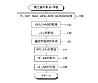
- (A) is the figure which showed the map used in order to acquire the target fuel injection amount TGF based on the accelerator pedal opening degree Dac
- (B) is the target based on the fuel injection amount GF and the engine speed N. It is the figure which showed the map used in order to acquire a throttle valve opening degree. It is the figure which showed an example of the routine which performs calculation and learning of the fuel injection amount correction value and intake air amount correction value of this invention. It is the figure which showed an example of the routine which performs the failure diagnosis of the fuel injection valve of this invention, and an airflow meter.
- FIG. 1 shows an internal combustion engine to which the control device of the present invention is applied.
- An internal combustion engine 10 shown in FIG. 1 includes a main body (hereinafter referred to as “engine main body”) 20 of an internal combustion engine, fuel injection valves 21 respectively disposed corresponding to four combustion chambers of the engine main body, A fuel pump 22 for supplying fuel to the fuel injection valve 21 via a fuel supply pipe 23 is provided.
- the internal combustion engine 10 further includes an intake system 30 that supplies air to the combustion chamber from the outside, and an exhaust system 40 that exhausts exhaust gas discharged from the combustion chamber to the outside.
- the internal combustion engine 10 is a compression self-ignition internal combustion engine (so-called diesel engine).
- the intake system 30 includes an intake branch pipe 31 and an intake pipe 32.
- the intake system 30 may be referred to as an “intake passage”.
- One end portion (that is, a branch portion) of the intake branch pipe 31 is connected to an intake port (not shown) formed in the engine body 20 corresponding to each combustion chamber.
- the other end of the intake branch pipe 31 is connected to the intake pipe 32.
- a throttle valve 33 that controls the amount of air flowing through the intake pipe is disposed in the intake pipe 32.
- an intercooler 34 for cooling the air flowing through the intake pipe is disposed in the intake pipe 32.
- an air cleaner 36 is disposed at an end facing the outside of the intake pipe 32.
- the exhaust system 40 includes an exhaust branch pipe 41 and an exhaust pipe 42.
- the exhaust system 40 may be referred to as an “exhaust passage”.
- One end portion (that is, a branch portion) of the exhaust branch pipe 41 is connected to an exhaust port (not shown) formed in the engine body 20 corresponding to each combustion chamber.
- the other end of the exhaust branch pipe 41 is connected to the exhaust pipe 42.
- a catalytic converter 43 having an exhaust purification catalyst 43A for purifying a specific component in the exhaust gas is disposed.
- an oxygen concentration sensor that outputs an output value corresponding to the oxygen concentration in the exhaust gas discharged from the combustion chamber (hereinafter referred to as “upstream side of the oxygen concentration sensor”) is output to the exhaust pipe 42 upstream of the exhaust purification catalyst 43A.
- 76U (referred to as“ oxygen concentration sensor ”) is attached.
- an oxygen concentration sensor that outputs an output value corresponding to the oxygen concentration in the exhaust gas flowing out from the exhaust purification catalyst 43A is supplied to the exhaust pipe 42 downstream of the exhaust purification catalyst 43A (hereinafter, this oxygen concentration sensor is referred to as “downstream”).
- 76D (referred to as“ side oxygen concentration sensor ”) is attached.
- a sensor that outputs an output value corresponding to the concentration of NOx (nitrogen oxide) in the exhaust gas exhausted from the combustion chamber is provided in the exhaust pipe 42 upstream of the exhaust purification catalyst 43A (hereinafter referred to as “sensor”). 77 ”(referred to as“ NOx sensor ”) is attached.
- intake air amount the flow rate of air flowing through the intake pipe (therefore, the flow rate of air sucked into the combustion chamber, hereinafter referred to as “intake air amount”).
- intake air amount the flow rate of air flowing through the intake pipe
- intake air amount the flow rate of air sucked into the combustion chamber
- An air flow meter 71 for outputting the output value is attached.
- the intake branch pipe 31 is attached with a pressure sensor (hereinafter referred to as “intake pressure sensor”) 72 that outputs an output value corresponding to the pressure of the gas in the intake branch pipe (that is, intake pressure).
- intake pressure sensor a pressure sensor that outputs an output value corresponding to the pressure of the gas in the intake branch pipe (that is, intake pressure).
- crank position sensor 74 that outputs an output value corresponding to the rotational phase of the crankshaft is attached to the engine body 20.
- the internal combustion engine 10 includes an electronic control device 60.
- the electronic control device 60 includes a microprocessor (CPU) 61, a read only memory (ROM) 62, a random access memory (RAM) 63, a backup RAM (Back up RAM) 64, and an interface 65.
- the fuel injection valve 21, the fuel pump 22, and the throttle valve 33 are connected to the interface 65, and a control signal for controlling these operations is given from the electronic control device 60 through the interface 65.
- the interface 65 includes an air flow meter 71, an intake pressure sensor 72, a crank position sensor 74, and an opening degree of the accelerator pedal AP (that is, the depression amount of the accelerator pedal AP.
- the accelerator pedal opening sensor 75, the upstream oxygen concentration sensor 76U, the downstream oxygen concentration sensor 76D, and the NOx sensor 77 are also connected and output from the air flow meter 71.
- the output value output from the downstream oxygen concentration sensor 76D, and the NOx concentration Output value outputted from the sub 77 is input to the interface 65.
- the electronic control unit 60 calculates the intake air amount based on the output value of the air flow meter 71, calculates the intake pressure based on the output value of the intake pressure sensor 72, and determines the engine based on the output value of the crank position sensor 74.
- the number of revolutions (that is, the number of revolutions of the internal combustion engine) is calculated, the accelerator pedal opening is calculated based on the output value of the accelerator pedal opening sensor 75, and from the combustion chamber based on the output value of the upstream oxygen concentration sensor 76U.
- the air-fuel ratio of the exhaust gas that is exhausted and before flowing into the exhaust purification catalyst 43A (that is, the air-fuel ratio of the air-fuel mixture formed in the combustion chamber) is calculated, and the output value of the downstream oxygen concentration sensor 76D Based on this, the air-fuel ratio of the exhaust gas flowing out from the exhaust purification catalyst 43A is calculated. Since the upstream oxygen concentration sensor 76U can be said to detect the air-fuel ratio of the air-fuel mixture formed in the combustion chamber, in the following description, the upstream oxygen concentration sensor is simply referred to as “air-fuel ratio sensor”. And
- engine operation is “operation of the internal combustion engine”
- fuel injection amount is “amount of fuel injected from the fuel injection valve”
- actual fuel injection amount is “fuel The amount of fuel actually injected from the injection valve ”.
- an appropriate fuel injection amount is obtained in advance by experiments or the like in accordance with the accelerator pedal opening, and these fuel injection amounts are determined as shown in FIG.
- the target fuel injection amount TGF is stored in the electronic control unit in the form of a Dac function map.
- the target fuel injection amount TGF is acquired from the map of FIG. 2A according to the accelerator pedal opening degree Dac.
- a valve opening time of the fuel injection valve necessary for injecting the fuel of the acquired target fuel injection amount TGF into the fuel injection valve (hereinafter, this valve opening time is referred to as “target valve opening time”) is calculated.
- a command value for opening the fuel injection valve for the calculated valve opening time hereinafter, this command value is referred to as “fuel injection command value” is given to the fuel injection valve.
- an appropriate throttle valve opening (that is, the throttle valve opening) corresponding to the fuel injection amount and the engine speed is determined in advance through experiments or the like.
- the obtained throttle valve opening is electronically controlled in the form of a map of a function of the fuel injection amount GF and the engine speed N as the target throttle valve opening TDth as shown in FIG. It is stored in the device 60.
- the target throttle valve opening TDth is acquired from the map of FIG. 2B based on the fuel injection amount GF and the engine speed N.
- the opening of the throttle valve is controlled so that the throttle valve is opened by the acquired target throttle valve opening TDth.
- the target throttle valve opening TDth increases as the fuel injection amount GF increases, and the target throttle valve opening TDth increases as the engine speed N increases.
- the target fuel injection amount TGF (that is, from the map of FIG. 2A) is used as the fuel injection amount GF used for acquiring the target throttle valve opening TDth from the map of FIG.
- the acquired target fuel injection amount TGF is employed.
- this fuel injection valve when a fuel injection valve having standard characteristics (hereinafter, this fuel injection valve is referred to as a “reference fuel injection valve”), a target fuel injection amount of fuel is used as the reference fuel.
- a function that can calculate the fuel injection command value that can be injected from the injection valve is obtained in advance by experiments or the like, and the fuel injection command value is calculated by applying the target fuel injection amount to this function during engine operation. Is done. Therefore, as long as the characteristics of the fuel injection valve match the characteristics of the reference fuel injection valve, if the fuel injection command value calculated by the above function is given to the fuel injection valve, the fuel of the target fuel injection amount is discharged from the fuel injection valve.
- the actual fuel injection amount matches the target fuel injection amount.
- the characteristics of the fuel injector do not match the characteristics of the reference fuel injector due to manufacturing errors of the fuel injector, or the characteristics of the fuel injector due to deterioration of the fuel injector over time, etc. Is no longer equal to the reference fuel injection valve, even if the fuel injection command value calculated by the above function is given to the fuel injection valve, the target fuel injection amount of fuel is not injected from the fuel injection valve. That is, the actual fuel injection amount does not match the target fuel injection amount.
- a fuel injection amount correction value (details will be described later) representing a deviation of the actual fuel injection amount with respect to the target fuel injection amount is calculated and calculated by the above function.
- the fuel injection command value is corrected by multiplying the fuel injection command value by the reciprocal of the calculated fuel injection amount correction value, and the corrected fuel injection command value is used as the final fuel injection command value.
- the actual fuel injection amount matches the target fuel injection amount, or at least the actual fuel injection amount approaches the target fuel injection amount.
- the fuel injection command value corrected according to the present invention is not only used to bring the actual fuel supply amount close to the target fuel injection amount, but also executes a control in which the internal combustion engine uses the fuel injection amount as one parameter. In such a case, the fuel injection amount may be used for grasping.
- an air flow meter output value is converted into an actual intake air amount when an air flow meter having standard characteristics (hereinafter referred to as “reference air flow meter”) is used as a reference.
- a function to be obtained is obtained in advance by experiments or the like, and the intake air amount is calculated as the detected intake air amount by applying the output value of the air flow meter to this function during engine operation. Therefore, as long as the characteristics of the air flow meter match the characteristics of the reference air flow meter, the detected intake air amount calculated by the above function matches the actual intake air amount.
- the characteristics of the air flow meter do not match the characteristics of the reference air flow meter due to manufacturing errors of the air flow meter, or the characteristics of the air flow meter change to the reference air flow meter due to deterioration of the air flow meter over time, etc. If they do not match, the detected intake air amount calculated by the above function does not match the actual intake air amount.
- an intake air amount correction value (details will be described later) representing a deviation of the detected intake air amount with respect to the actual intake air amount is calculated and calculated by the above function.
- the detected intake air amount is corrected by multiplying the calculated detected intake air amount by the calculated intake air amount correction value, and this corrected detected intake air amount is set as the final detected intake air amount.
- the detected intake air amount matches the actual intake air amount, or at least the detected intake air amount approaches the actual intake air amount.
- the detected intake air amount corrected according to the present invention is used, for example, when the internal combustion engine performs control using the detected intake air amount as one parameter.
- the instantaneous value XFI of the fuel injection amount correction value and the instantaneous value XAI of the intake air amount correction value are calculated by solving simultaneous equations consisting of the following equations 1 and 2 during engine operation. Is done.
- Equation 1 “AFd” is “detected air-fuel ratio (that is, the air-fuel ratio of the air-fuel mixture detected by the air-fuel ratio sensor)”, and “AFe” is “estimated air-fuel ratio”.
- NOXd is “detected NOx concentration”
- Fnox is “a model or function for calculating the NOx concentration in the exhaust gas from the fuel injection amount and the intake air amount”.
- GFe is “command fuel injection amount (that is, fuel injection amount grasped from fuel injection command value calculated based on current target fuel injection amount”)
- GAd is “detected intake air amount”.
- AFd AFe ⁇ XAI / XFI (1)
- NOXd Fnox (GFe ⁇ XFI, GAd ⁇ XAI) (2)
- Equation 3 the estimated air-fuel ratio AFe used in Equation 1 is calculated according to the following Equation 3.
- GAd is “detected intake air amount”
- GFe is “command fuel injection amount (that is, fuel injection grasped from the fuel injection command value calculated based on the current target fuel injection amount). Amount) ".
- Equation 4 “XFG” is “a learned value of the fuel injection amount correction value acquired according to the current engine operating state”, and “XFI” is “the instantaneous value of the fuel injection amount correction value calculated this time” It is.
- XAG is “a learned value of the fuel injection amount correction value acquired according to the current engine operating state”, and “XAI” is “the instantaneous value of the intake air amount correction value calculated this time” Is.
- the newly calculated fuel injection amount correction value is used as the learning value of the fuel injection amount correction value corresponding to the current engine operating state. Is remembered. That is, the learning value of the fuel injection amount correction value corresponding to the current engine operating state is updated.
- the newly calculated intake air amount correction value is used as the learned value of the intake air amount correction value corresponding to the current engine operating state. Is remembered. That is, the learning value of the intake air amount correction value corresponding to the current engine operating state is updated.
- the actual fuel injection amount matches the target fuel injection amount by correcting the fuel injection command value with the fuel injection amount correction value calculated as described above (or the actual fuel injection amount is the target fuel injection amount).
- the detected intake air amount matches the actual intake air amount (or the detected intake air amount is The reason for approaching the intake air amount will be described.
- the actual intake air amount is represented by “GAa” and the detected intake air amount is represented by “GAd”, the actual intake air amount is obtained by dividing the actual intake air amount by the detected intake air amount as represented by the following equation (6).
- the obtained value XA is defined as an intake air amount detection error (that is, an error in the detected intake air amount with respect to the actual intake air amount).
- the actual fuel injection amount is represented by “GFa”, and the command fuel injection amount (that is, the fuel injection amount grasped from the fuel injection command value calculated based on the current target fuel injection amount) is represented by “GFe”.
- the value XF obtained by dividing the actual fuel injection amount by the target fuel injection amount as expressed by the following equation 7 is set to a fuel injection amount error (that is, the actual fuel injection amount with respect to the target fuel injection amount). Error).
- the detected intake air amount is represented by “GAd” and the command fuel injection amount is represented by “GFe”
- the detected intake air amount is obtained by dividing the detected intake air amount by the command fuel injection amount as shown in the following equation (8).
- the resulting value AFe is defined to be the estimated air / fuel ratio.
- the value NOXe calculated according to the following equation 9 is defined as “estimated NOx concentration”.
- XA GAa / GAd (6)
- XF GFa / GFe (7)
- AFe GAd / GFe (8)
- NOXe Fnox (GFe, GAd) (9)
- the intake air amount detection error XA, the fuel injection amount error XF, the estimated air-fuel ratio AFe, and the estimated NOx concentration NOXe are defined as described above, there is a following equation between the actual air-fuel ratio AFa and the estimated air-fuel ratio AFe: 10 is established, and the relationship of the following equation 11 is established between the detected NOx concentration (that is, the actual NOx concentration) NOXd and the estimated NOx concentration NOXe.
- AFa AFe ⁇ XA / XF (10)
- NOXa Fnox (GFe ⁇ XF, GAd ⁇ XA) (11)
- the fuel injection amount error XF and the intake air amount detection error XA can be calculated by solving the simultaneous equations consisting of Equations 10 and 11. Since Equation 10 corresponds to Equation 1 and Equation 11 corresponds to Equation 2, solving the simultaneous equations consisting of Equation 10 and Equation 11 (that is, simultaneous equations consisting of Equation 1 and Equation 2)
- the fuel injection amount error XF obtained by the above equation is a correction value that matches the actual fuel injection amount with the target fuel injection amount (that is, the fuel injection amount correction value), and is a simultaneous equation consisting of Equation 10 and Equation 11 (that is, Equation
- the intake air amount detection error XA obtained by solving the simultaneous equations (1) and (2) is a correction value that matches the detected intake air amount with the actual intake air amount (that is, the intake air amount correction value). become.
- the fuel injection command value is corrected without excess or deficiency with respect to the fuel injection amount error of the fuel injection valve, and the detected intake air amount with respect to the detected intake air amount error with the air flow meter is not excessive or deficient. It is corrected. The reason for this will be described below.
- the above equation 1 is an equation that holds for the detected air-fuel ratio and the estimated air-fuel ratio
- the above equation 2 is an equation that holds for the detected NOx concentration and the estimated NOx concentration. Therefore, these equations are equations of different nature.
- the estimated air-fuel ratio in the above equation 1 is calculated from the command fuel injection amount and the detected intake air amount
- the estimated NOx concentration in the above equation 2 is also calculated from the command fuel injection amount and the detected intake air amount.
- the command fuel injection amount and the detected intake air amount are parameters having different properties. As described above, in the above-described embodiment, two equations having different properties are used to calculate correction values for correcting two parameters having different properties.
- the equations 1 and 2 regulate the fuel injection amount correction value and the intake air amount correction value, in the above-described embodiment, correction values for correcting two parameters having different properties from each other. It can be said that two regulations having different properties are adopted in the calculation of the above. Therefore, the fuel injection command value and the detected intake air amount are corrected based on the fuel injection amount correction value and the intake air amount correction value calculated according to the above-described embodiment, so that the fuel is compensated for the fuel injection amount error of the fuel injection valve.
- the injection command value is corrected without excess or deficiency
- the detected intake air amount is corrected without excess or deficiency with respect to the detected intake air amount error of the air flow meter.
- the output torque of the internal combustion engine will greatly fluctuate.
- the embodiment described above according to the embodiment described above, not only the fuel injection amount but also the intake air amount is corrected. Therefore, the output torque of the internal combustion engine is prevented from greatly fluctuating.
- the fuel injection amount correction value and the intake air amount correction value calculated by solving the simultaneous equations consisting of the above formulas 1 and 2 are the deviations between the detected air-fuel ratio and the estimated air-fuel ratio.
- the deviation between the detected NOx concentration and the estimated NOx concentration can be said to be correction values that simultaneously set “0” or at least reduce the deviation.
- step 100 the engine speed N, the target fuel injection amount TGF, the detected intake air amount GAd, the command fuel injection amount GFe, the detected air-fuel ratio AFd, and the detected NOx concentration NOXd are acquired. Is done.
- step 101 the learning value XFG of the fuel injection amount correction value and the learning of the intake air amount correction value corresponding to the engine operating state defined by the engine speed N and the target fuel injection amount TGF obtained at step 100 are learned.
- a value XAG is obtained.
- step 102 the estimated air-fuel ratio AFe is calculated by applying the detected intake air amount GAd and the command fuel injection amount GFe acquired at step 100 to the above equation 3.
- step 103 the estimated air-fuel ratio AFe calculated in step 102 is applied to the above equation 1, and the detected intake air amount GAd and the command fuel injection amount GFe acquired in step 100 are applied to the above equation 2. Simultaneous equations are created.
- step 104 the instantaneous value XFI of the fuel injection amount correction value and the instantaneous value XAI of the intake air amount correction value are calculated by solving the simultaneous equations created in step 103.
- step 105 the fuel injection amount is calculated by applying the learned value XFG of the fuel injection amount correction value acquired at step 101 and the instantaneous value XFI of the fuel injection amount correction value calculated at step 104 to the above equation 4.
- step 106 the engine operating state in which the fuel injection amount correction value XF and the intake air amount correction value XA calculated at step 105 are defined by the engine speed N and the target fuel injection amount TGF acquired at step 100.
- a range that can be taken as a learned value of the fuel injection amount correction value when a failure has not occurred in the fuel injection valve is set in advance, and the learned value of the fuel injection amount correction value is set in advance. If the fuel injection valve is not within the specified range, it may be diagnosed that a failure has occurred in the fuel injection valve.
- failure of the fuel injection valve can be diagnosed more accurately. That is, the learned value of the fuel injection amount correction value accurately represents the fuel injection amount error of the fuel injection valve. Therefore, the failure diagnosis of the fuel injection valve is performed using the learning value of the fuel injection amount correction value, which is a parameter that accurately represents the fuel injection amount error of the fuel injection valve. A more accurate diagnosis can be made.
- the learning value of the fuel injection amount correction value reflects a decrease in exhaust emission characteristics. Therefore, since the failure diagnosis of the fuel injection valve is performed using the learned value of the fuel injection amount correction value, which is a parameter reflecting such a decrease in exhaust emission characteristics, the fuel injection is performed even when the exhaust emission characteristics are deteriorated. It can be said that the failure of the valve can be accurately diagnosed, and by extension, the failure of the fuel injection valve can be reliably diagnosed before the degree of failure of the fuel injection valve becomes large.
- a range that can be taken as a learning value for the intake air amount correction value when a failure has not occurred in the air flow meter is set in advance, and the learning value for the intake air amount correction value is set in advance. If the air flow meter is not within the specified range, it may be diagnosed that a failure has occurred in the air flow meter. According to this, the failure of the air flow meter can be diagnosed more accurately. That is, the learning value of the intake air amount correction value accurately represents the detected intake air amount error of the air flow meter. Therefore, the failure diagnosis of the air flow meter is performed by using the learning value of the intake air amount correction value, which is a parameter that accurately represents the detected intake air amount error of the air flow meter.
- the learning value of the intake air amount correction value reflects a decrease in exhaust emission characteristics. Therefore, since the failure diagnosis of the air flow meter is performed using the learned value of the intake air amount correction value, which is a parameter reflecting such a decrease in the exhaust emission characteristic, the air flow meter of the air flow meter is reduced even when the exhaust emission characteristic is deteriorated. It can be said that the failure can be accurately diagnosed, and by extension, the failure of the air flow meter can be surely diagnosed before the degree of failure of the air flow meter becomes large.
- step 200 the most recently learned learning value XFG of the fuel injection amount correction value and the learning value XAG of the intake air amount correction value are acquired.
- step 201 it is determined whether or not the learned value XFG of the fuel injection amount correction value acquired at step 200 is within a range determined by the lower limit value XFGmin and the upper limit value XFGmax (XFGmin ⁇ XFG ⁇ XFGmax). Is done.
- the routine proceeds to step 202 as it is.
- step 203 displays that the fuel injection valve has failed, and then proceeds to step 202.
- step 202 whether or not the learning value XAG of the intake air amount correction value acquired in step 200 is within a range determined by the lower limit value XAGmin and the upper limit value XAGmax (XAGmin ⁇ XAG ⁇ XAGmax). Is determined.
- step 204 the routine proceeds to step 204 to display that the air flow meter has failed, and thereafter the routine ends.
- an upper limit value and a lower limit value related to the fuel injection amount correction value may be provided, and the fuel injection amount correction value may be limited to these upper limit value and lower limit value, or an upper limit value related to the intake air amount correction value.
- a lower limit value may be provided, and the intake air amount correction value may be limited to the upper limit value and the lower limit value.
- an upper limit value and a lower limit value relating to the fuel injection amount correction value an upper limit calculated based on an error that may occur due to deterioration of the fuel injection valve, machine difference, or both, as the upper limit value and the lower limit value. Values and lower limits can be used.
- the lower limit can be adopted.
- the correction of the fuel injection command value based on the fuel injection amount correction value and the correction of the detected intake air amount based on the intake air amount correction value have no or little influence on exhaust emissions such as NOx. It is clear that this is not the case, or the fuel injection amount error of the fuel injection valve is not caused by a steady deviation of the fuel injection valve characteristic from the reference characteristic, but in one cycle or a plurality of When it is clear that there is a variation between a plurality of fuel injections in the cycle, or the error of the estimated air-fuel ratio with respect to the detected air-fuel ratio is the air-fuel ratio detection error of the air-fuel ratio sensor or the NOx concentration detection error of the NOx sensor Or if it is clear that this is due to a NOx concentration estimation error in the NOx concentration estimation model, Learning amount correction value and the intake air amount correction value may be prohibited.
- an engine operation state suitable for calculating the fuel injection amount correction value and the intake air amount correction value is set in advance, and when the engine operation state is the preset engine operation state, the fuel is The injection amount correction value and the intake air amount correction value are calculated, and the fuel injection amount correction value and the intake air amount correction value are not calculated when the engine operation state is not in the preset engine operation state. Good. According to this, calculation of an inappropriate fuel injection amount correction value and intake air amount correction value can be avoided, and exhaust emission characteristics can be stabilized.
- the engine operating state suitable for calculating the fuel injection amount correction value and the intake air amount correction value is, for example, that the temperature of the air-fuel ratio sensor has reached its activation temperature, and the temperature of the NOx sensor has reached its activation temperature. That the air-fuel ratio of the air-fuel ratio sensor (for example, the pressure of the exhaust gas around the air-fuel ratio sensor or the oxygen concentration in the exhaust gas around the air-fuel ratio sensor) is detected by the air-fuel ratio sensor.
- the state within the possible range, the state of the atmosphere around the NOx sensor (for example, the pressure of the exhaust gas around the NOx sensor, or the oxygen concentration in the exhaust gas around the NOx sensor) is the NOx concentration by the NOx sensor.
- the engine speed, intake pressure, or intake air amount is within a range that allows detection, whether the air-fuel ratio can be detected by the air-fuel ratio sensor, or The engine speed, intake pressure, or intake air amount within the allowable range from the viewpoint of the accuracy of air-fuel ratio detection by the ratio sensor, engine speed, intake pressure, or intake air amount Is whether the NOx concentration can be detected by the NOx sensor, or the engine speed, the intake pressure, or the intake air amount within the allowable range from the viewpoint of the accuracy of the NOx concentration detection by the NOx sensor,
- the engine operating state satisfies one or more of the conditions that the operating state is an engine operating state in which Expressions 1 and 2 are satisfied.
- the fuel injection amount correction value and the intake air amount correction value are calculated using the NOx concentration in the exhaust gas.
- the present invention is also applicable to the case where the fuel injection amount correction value and the intake air amount correction value are calculated using the NOx amount in the exhaust gas.
- the fuel injection amount correction value and the intake air amount correction value are calculated using the NOx concentration in the exhaust gas.
- the present invention uses the concentration of unburned hydrocarbon (HC) or the concentration of carbon monoxide (CO) in the exhaust gas instead of the NOx concentration in the exhaust gas, and the fuel injection amount correction value and the intake air amount correction value. It is applicable also when calculating. That is, the present invention is broadly applicable to the case where the fuel injection amount correction value and the intake air amount correction value are calculated using the concentration of the specific component in the exhaust gas. The present invention is broadly applicable to the case where the fuel injection amount correction value and the intake air amount correction value are calculated using the amount of the specific component in the exhaust gas. Note that the concentration of the specific component here varies depending on the fuel injection amount and the intake air amount.
- the fuel injection valve injects fuel into the combustion chamber when it receives a command to inject fuel from the electronic control unit. Therefore, it can be said that the fuel injection valve is a fuel supply means for supplying fuel to the combustion chamber.
- the air flow meter outputs an output value corresponding to the amount of air supplied to the combustion chamber to the electronic control unit. Then, the electronic control unit calculates the amount of air supplied to the combustion chamber based on this output value. Therefore, it can be said that the air flow meter is a supply air amount detection means.
- the air-fuel ratio sensor outputs an output value corresponding to the oxygen concentration in the exhaust gas arriving there to the electronic control unit. Then, the electronic control unit calculates the air-fuel ratio of the air-fuel mixture formed in the combustion chamber based on this output value.
- the air-fuel ratio sensor is an air-fuel ratio detection means.
- the NOx sensor outputs an output value corresponding to the NOx concentration in the exhaust gas arriving there to the electronic control unit. Then, the electronic control unit calculates the NOx concentration in the exhaust gas based on this output value. Therefore, it can be said that the NOx sensor is a NOx concentration detecting means. If NOx is regarded as a specific component in the exhaust gas, the NOx sensor can be said to be an exhaust component concentration detecting means for detecting the concentration of the specific component in the exhaust gas.
- the electronic control unit sets the amount of fuel to be injected into the combustion chamber by the fuel injection valve as the target fuel injection amount. Therefore, it can be said that the electronic control device has a function as target fuel injection amount setting means. Further, the electronic control unit calculates a fuel injection command value for injecting fuel of the target fuel injection amount from the fuel injection valve into the combustion chamber based on the target fuel injection amount, and gives the fuel injection command value to the fuel injection valve. . Therefore, it can be said that the electronic control device has a function as a fuel injection command value providing means. The electronic control unit calculates the air-fuel ratio of the air-fuel mixture formed in the combustion chamber from the fuel injection amount and the intake air amount. Therefore, it can be said that the electronic control device has a function as air-fuel ratio calculation means.
- the electronic control unit calculates the NOx concentration in the exhaust gas discharged from the combustion chamber from the fuel injection amount and the intake air amount. Therefore, it can be said that the electronic control device has a function as NOx concentration calculation means. If NOx is regarded as a specific component in the exhaust gas, the electronic control unit calculates the concentration of the specific component in the exhaust gas discharged from the combustion chamber from the fuel injection amount and the intake air amount. It can be said that it has the function as.
- the above-described embodiment is an embodiment in which the present invention is applied to a compression self-ignition internal combustion engine.
- the present invention is also applicable to a spark ignition type internal combustion engine.
Abstract
Description
NOXd=Fnox(GFe×XFI,GAd×XAI) …(2)
XA=XAG+XAI …(5)
XF=GFa/GFe …(7)
AFe=GAd/GFe …(8)
NOXe=Fnox(GFe,GAd) …(9)
NOXa=Fnox(GFe×XF,GAd×XA) …(11)
Claims (5)
- 燃焼室に燃料を供給する燃料供給手段と、該燃料供給手段によって燃焼室に供給されるべき燃料の量を目標燃料供給量として設定する目標燃料供給量設定手段と、該目標燃料供給量設定手段によって設定される目標燃料供給量の燃料を前記燃料供給手段から燃焼室に供給させるための燃料供給指令値を目標燃料供給量に基づいて算出して該燃料供給指令値を前記燃料供給手段に与える燃料噴射指令値提供手段と、燃焼室に供給される空気の量を検出する供給空気量検出手段と、燃焼室に形成される混合気の空燃比を検出する空燃比検出手段と、前記燃料供給指令値から把握される燃料供給量と前記供給空気量検出手段によって検出される空気の量とから燃焼室に形成される混合気の空燃比を算出する空燃比算出手段と、燃焼室から排出される排気ガス中の特定成分の濃度を検出する排気成分濃度検出手段と、前記燃料供給指令値から把握される燃料噴射量と前記供給空気量検出手段によって検出される空気の量とから燃焼室から排出される排気ガス中の特定成分の濃度を算出する排気成分濃度算出手段と、を具備する内燃機関の制御装置において、
前記空燃比検出手段によって検出される空燃比と前記空燃比算出手段によって算出される空燃比との間の偏差と前記排気成分濃度検出手段によって検出される特定成分の濃度と前記排気成分濃度算出手段によって算出される特定成分の濃度との間の偏差とが小さくなるように前記燃料供給指令値または該燃料供給指令値から把握される燃料供給量が補正されるとともに前記供給空気量検出手段によって検出される空気の量が補正される内燃機関の制御装置。 - 前記特定成分が排気ガス中に含まれる窒素酸化物である請求項1に記載の内燃機関の制御装置。
- 前記燃料供給手段によって供給される燃料の量に関する誤差を解消する補正値を燃料供給量補正値と称し、前記供給空気量検出手段によって検出される空気の量に関する誤差を解消する補正値を供給空気量補正値と称したとき、これら燃料供給量補正値および供給空気量補正値を用いて前記空燃比検出手段によって検出される空燃比と前記空燃比算出手段によって算出される空燃比との間に成立する等式と前記排気成分濃度検出手段によって検出される特定成分の濃度と前記排気成分濃度算出手段によって算出される特定成分の濃度との間に成立する等式とが構成され、これら2つの等式からなる連立方程式を解くことによって燃料供給量補正値および供給空気量補正値が算出され、前記燃料供給指令値または該燃料供給指令値から把握される燃料供給量が前記算出された燃料供給量補正値によって補正されるとともに前記供給空気量検出手段によって検出される空気の量が前記算出された供給空気量補正値によって補正されることによって前記空燃比検出手段によって検出される空燃比と前記空燃比算出手段によって算出される空燃比との間の偏差と前記排気成分濃度検出手段によって検出される特定成分の濃度と前記排気成分濃度算出手段によって算出される特定成分の濃度との間の偏差とが小さくされる請求項1または2に記載の内燃機関の制御装置。
- 前記燃料供給手段に故障が生じていない場合に前記燃料供給指令値に対する補正量が取り得る範囲が燃料供給指令値補正許容範囲として設定され、前記燃料供給指令値に対する補正量が該燃料供給指令値補正許容範囲内にないときに前記燃料供給手段に故障が生じていると診断される請求項1~3のいずれか1つに記載の内燃機関の制御装置。
- 前記供給空気量検出手段に故障が生じていない場合に前記検出供給空気量に対する補正量が取り得る範囲が検出供給空気量補正許容範囲として設定され、前記燃料供給指令値に対する補正量が該検出供給空気量補正許容範囲内にないときに前記供給空気量検出手段に故障が生じていると診断される請求項1~4のいずれか1つに記載の内燃機関の制御装置。
Priority Applications (5)
| Application Number | Priority Date | Filing Date | Title |
|---|---|---|---|
| US13/390,394 US9194322B2 (en) | 2011-05-11 | 2011-05-11 | Control device of an engine |
| CN201180016526.3A CN102884299B (zh) | 2011-05-11 | 2011-05-11 | 内燃机的控制装置 |
| PCT/JP2011/060858 WO2012153403A1 (ja) | 2011-05-11 | 2011-05-11 | 内燃機関の制御装置 |
| EP11824288.2A EP2708724B1 (en) | 2011-05-11 | 2011-05-11 | Control device for internal combustion engine |
| JP2011538753A JP5083583B1 (ja) | 2011-05-11 | 2011-05-11 | 内燃機関の制御装置 |
Applications Claiming Priority (1)
| Application Number | Priority Date | Filing Date | Title |
|---|---|---|---|
| PCT/JP2011/060858 WO2012153403A1 (ja) | 2011-05-11 | 2011-05-11 | 内燃機関の制御装置 |
Publications (1)
| Publication Number | Publication Date |
|---|---|
| WO2012153403A1 true WO2012153403A1 (ja) | 2012-11-15 |
Family
ID=47138905
Family Applications (1)
| Application Number | Title | Priority Date | Filing Date |
|---|---|---|---|
| PCT/JP2011/060858 WO2012153403A1 (ja) | 2011-05-11 | 2011-05-11 | 内燃機関の制御装置 |
Country Status (5)
| Country | Link |
|---|---|
| US (1) | US9194322B2 (ja) |
| EP (1) | EP2708724B1 (ja) |
| JP (1) | JP5083583B1 (ja) |
| CN (1) | CN102884299B (ja) |
| WO (1) | WO2012153403A1 (ja) |
Families Citing this family (10)
| Publication number | Priority date | Publication date | Assignee | Title |
|---|---|---|---|---|
| US8869604B2 (en) * | 2010-09-08 | 2014-10-28 | Toyota Jidosha Kabushiki Kaisha | Flow rate detection device |
| WO2012157037A1 (ja) * | 2011-05-13 | 2012-11-22 | トヨタ自動車株式会社 | 内燃機関の制御装置 |
| JP6317219B2 (ja) * | 2013-11-29 | 2018-04-25 | トヨタ自動車株式会社 | 燃料性状推定装置 |
| DE102014211896A1 (de) * | 2014-06-20 | 2015-12-24 | Robert Bosch Gmbh | Verfahren zur Überwachung einer Fahrzeugsteuerung |
| AT516320B1 (de) * | 2014-10-06 | 2016-07-15 | Ge Jenbacher Gmbh & Co Og | Verfahren zum Betreiben einer Selbstzündungs-Brennkraftmaschine |
| TWI593875B (zh) * | 2016-01-21 | 2017-08-01 | Rong-Bin Liao | Engine control |
| US10480474B2 (en) * | 2017-04-06 | 2019-11-19 | Ge Global Sourcing Llc | Method and system for determining remaining useful life for an injector of a reciprocating engine |
| CN109113883B (zh) * | 2017-06-22 | 2020-07-07 | 联合汽车电子有限公司 | 内燃机的空燃比控制方法及装置 |
| CN111927640B (zh) * | 2020-08-19 | 2022-09-23 | 潍柴动力股份有限公司 | 发动机故障检测方法、装置、设备及计算机可读存储介质 |
| CN114673603B (zh) * | 2022-04-12 | 2023-04-14 | 中国第一汽车股份有限公司 | 发动机控制系统安全监控方法、装置、计算机设备和介质 |
Citations (5)
| Publication number | Priority date | Publication date | Assignee | Title |
|---|---|---|---|---|
| JPH06299886A (ja) | 1993-04-05 | 1994-10-25 | Ford Motor Co | フィードバック制御システム及び制御方法 |
| JP2007262946A (ja) | 2006-03-28 | 2007-10-11 | Toyota Motor Corp | 内燃機関の燃料供給制御装置 |
| WO2010090035A1 (ja) * | 2009-02-06 | 2010-08-12 | 本田技研工業株式会社 | 内燃機関の排気浄化装置及び排気浄化方法 |
| WO2010109667A1 (ja) * | 2009-03-27 | 2010-09-30 | 本田技研工業株式会社 | プラントの制御装置 |
| JP2011027059A (ja) * | 2009-07-28 | 2011-02-10 | Hitachi Automotive Systems Ltd | エンジンの制御装置 |
Family Cites Families (28)
| Publication number | Priority date | Publication date | Assignee | Title |
|---|---|---|---|---|
| JPH0718366B2 (ja) * | 1986-11-08 | 1995-03-06 | トヨタ自動車株式会社 | 内燃機関の空燃比制御装置 |
| JPH0758054B2 (ja) * | 1989-06-19 | 1995-06-21 | 株式会社ユニシアジェックス | 内燃機関の燃料供給制御装置における学習補正装置及び自己診断装置 |
| JPH03134240A (ja) * | 1989-10-18 | 1991-06-07 | Japan Electron Control Syst Co Ltd | 内燃機関の空燃比フィードバック制御装置 |
| US5115639A (en) * | 1991-06-28 | 1992-05-26 | Ford Motor Company | Dual EGO sensor closed loop fuel control |
| JPH06129285A (ja) * | 1992-10-20 | 1994-05-10 | Honda Motor Co Ltd | 内燃機関の空燃比制御装置 |
| US5426934A (en) * | 1993-02-10 | 1995-06-27 | Hitachi America, Ltd. | Engine and emission monitoring and control system utilizing gas sensors |
| US5738070A (en) * | 1996-12-11 | 1998-04-14 | Caterpillar Inc. | Method and apparatus for operation of a speed-governed lean burn engine to improve load response |
| US6705081B2 (en) * | 1997-07-15 | 2004-03-16 | New Power Concepts Llc | System and method for sensor control of the fuel-air ratio in a burner |
| JP2000110647A (ja) | 1998-09-30 | 2000-04-18 | Mazda Motor Corp | エンジンの制御装置 |
| JP3804402B2 (ja) * | 2000-05-19 | 2006-08-02 | トヨタ自動車株式会社 | 車両の駆動力制御装置及び駆動力制御方法 |
| JP4196535B2 (ja) * | 2000-11-02 | 2008-12-17 | トヨタ自動車株式会社 | 車両用制御装置および記録媒体 |
| JP3991619B2 (ja) * | 2000-12-26 | 2007-10-17 | 日産自動車株式会社 | 内燃機関の空燃比制御装置 |
| JP4490000B2 (ja) * | 2001-06-19 | 2010-06-23 | 本田技研工業株式会社 | 内燃機関の空燃比制御装置 |
| CA2441686C (en) * | 2003-09-23 | 2004-12-21 | Westport Research Inc. | Method for controlling combustion in an internal combustion engine and predicting performance and emissions |
| JP4552741B2 (ja) | 2005-04-19 | 2010-09-29 | 日産自動車株式会社 | エンジンの空燃比制御方法及びエンジンの空燃比制御装置 |
| US7389773B2 (en) * | 2005-08-18 | 2008-06-24 | Honeywell International Inc. | Emissions sensors for fuel control in engines |
| US7913675B2 (en) * | 2005-10-06 | 2011-03-29 | Caterpillar Inc. | Gaseous fuel engine charge density control system |
| JP4929966B2 (ja) | 2006-09-15 | 2012-05-09 | 株式会社デンソー | 燃料噴射制御装置 |
| US7680586B2 (en) * | 2006-12-20 | 2010-03-16 | Cummins Inc. | Mass air flow sensor signal compensation system |
| JP4221026B2 (ja) * | 2006-12-25 | 2009-02-12 | 三菱電機株式会社 | 内燃機関の空燃比制御装置 |
| JP2008215112A (ja) * | 2007-02-28 | 2008-09-18 | Mitsubishi Heavy Ind Ltd | ディーゼルエンジンシステム及びその制御方法 |
| DE102008000916B4 (de) * | 2007-04-02 | 2021-12-16 | Denso Corporation | Verbrennungssteuerungsvorrichtung für direkt einspritzende Kompressionszündungskraftmaschine |
| US7496443B2 (en) * | 2007-05-30 | 2009-02-24 | Ford Global Technologies, Llc | Emissions control |
| JP4479764B2 (ja) * | 2007-08-31 | 2010-06-09 | 株式会社デンソー | 燃料噴射制御装置およびそれを用いた燃料噴射システム |
| JP4782759B2 (ja) * | 2007-10-24 | 2011-09-28 | 株式会社デンソー | 内燃機関制御装置および内燃機関制御システム |
| JP2009115012A (ja) * | 2007-11-08 | 2009-05-28 | Denso Corp | 内燃機関の空燃比制御装置 |
| JP4672048B2 (ja) * | 2008-06-09 | 2011-04-20 | 三菱電機株式会社 | 内燃機関制御装置 |
| US8627858B2 (en) * | 2009-03-12 | 2014-01-14 | Ford Global Technologies, Llc | Methods and systems for selectively fuelling a vehicle |
-
2011
- 2011-05-11 CN CN201180016526.3A patent/CN102884299B/zh not_active Expired - Fee Related
- 2011-05-11 EP EP11824288.2A patent/EP2708724B1/en not_active Not-in-force
- 2011-05-11 US US13/390,394 patent/US9194322B2/en not_active Expired - Fee Related
- 2011-05-11 JP JP2011538753A patent/JP5083583B1/ja not_active Expired - Fee Related
- 2011-05-11 WO PCT/JP2011/060858 patent/WO2012153403A1/ja active Application Filing
Patent Citations (5)
| Publication number | Priority date | Publication date | Assignee | Title |
|---|---|---|---|---|
| JPH06299886A (ja) | 1993-04-05 | 1994-10-25 | Ford Motor Co | フィードバック制御システム及び制御方法 |
| JP2007262946A (ja) | 2006-03-28 | 2007-10-11 | Toyota Motor Corp | 内燃機関の燃料供給制御装置 |
| WO2010090035A1 (ja) * | 2009-02-06 | 2010-08-12 | 本田技研工業株式会社 | 内燃機関の排気浄化装置及び排気浄化方法 |
| WO2010109667A1 (ja) * | 2009-03-27 | 2010-09-30 | 本田技研工業株式会社 | プラントの制御装置 |
| JP2011027059A (ja) * | 2009-07-28 | 2011-02-10 | Hitachi Automotive Systems Ltd | エンジンの制御装置 |
Non-Patent Citations (1)
| Title |
|---|
| See also references of EP2708724A4 |
Also Published As
| Publication number | Publication date |
|---|---|
| JP5083583B1 (ja) | 2012-11-28 |
| JPWO2012153403A1 (ja) | 2014-07-28 |
| US9194322B2 (en) | 2015-11-24 |
| CN102884299A (zh) | 2013-01-16 |
| EP2708724A1 (en) | 2014-03-19 |
| CN102884299B (zh) | 2015-07-22 |
| US20140058646A1 (en) | 2014-02-27 |
| EP2708724B1 (en) | 2017-04-19 |
| EP2708724A4 (en) | 2015-02-11 |
Similar Documents
| Publication | Publication Date | Title |
|---|---|---|
| JP5083583B1 (ja) | 内燃機関の制御装置 | |
| JP4251073B2 (ja) | 内燃機関の制御装置 | |
| JP5093406B1 (ja) | 内燃機関の制御装置 | |
| JP2858288B2 (ja) | 内燃機関の空燃比制御装置における自己診断装置 | |
| US7725247B2 (en) | Abnormality diagnostic device and abnormality diagnostic method for air-fuel ratio sensor | |
| US7751966B2 (en) | Abnormality diagnostic device and abnormality diagnostic method for air-fuel ratio sensor | |
| US20120277979A1 (en) | Air/fuel ratio variation abnormality detection apparatus, and abnormality detection method | |
| JP2011027059A (ja) | エンジンの制御装置 | |
| US10138831B2 (en) | Controller and control method for internal combustion engine | |
| US20130226437A1 (en) | Air-fuel ratio variation abnormality detecting device and air-fuel ratio variation abnormality detecting method | |
| CN114508430A (zh) | 用于控制用于内燃机的氢气的喷入量的控制设备 | |
| JP5267600B2 (ja) | 多気筒内燃機関の制御装置 | |
| US7874143B2 (en) | Air-fuel ratio control apparatus of internal combustion engine and control method thereof | |
| US9404431B2 (en) | Method and device for operating an internal combustion engine | |
| JP5273224B2 (ja) | 内燃機関の空燃比制御装置 | |
| JP2010048125A (ja) | 内燃機関のセンサ故障判定装置 | |
| JP2014181650A (ja) | 多気筒型内燃機関の異常検出装置 | |
| JP5695878B2 (ja) | 内燃機関の燃焼制御装置及び方法 | |
| JP3991292B2 (ja) | 内燃機関の排気浄化装置及び排気浄化方法 | |
| JP5260770B2 (ja) | エンジンの制御装置 | |
| JP2013241867A (ja) | 内燃機関の制御装置 | |
| JP2010112353A (ja) | 内燃機関の空燃比制御装置 | |
| JP2005030407A (ja) | 内燃機関の排気浄化装置及び排気浄化方法 | |
| WO2014083626A1 (ja) | 内燃機関の制御装置 | |
| CN115875148A (zh) | 发动机的空燃比控制装置及控制方法 |
Legal Events
| Date | Code | Title | Description |
|---|---|---|---|
| WWE | Wipo information: entry into national phase |
Ref document number: 201180016526.3 Country of ref document: CN |
|
| ENP | Entry into the national phase |
Ref document number: 2011538753 Country of ref document: JP Kind code of ref document: A |
|
| WWE | Wipo information: entry into national phase |
Ref document number: 13390394 Country of ref document: US |
|
| REEP | Request for entry into the european phase |
Ref document number: 2011824288 Country of ref document: EP |
|
| WWE | Wipo information: entry into national phase |
Ref document number: 2011824288 Country of ref document: EP |
|
| 121 | Ep: the epo has been informed by wipo that ep was designated in this application |
Ref document number: 11824288 Country of ref document: EP Kind code of ref document: A1 |
|
| NENP | Non-entry into the national phase |
Ref country code: DE |