WO2012141297A1 - ガス軟窒化用熱延鋼板及びその製造方法 - Google Patents
ガス軟窒化用熱延鋼板及びその製造方法 Download PDFInfo
- Publication number
- WO2012141297A1 WO2012141297A1 PCT/JP2012/060151 JP2012060151W WO2012141297A1 WO 2012141297 A1 WO2012141297 A1 WO 2012141297A1 JP 2012060151 W JP2012060151 W JP 2012060151W WO 2012141297 A1 WO2012141297 A1 WO 2012141297A1
- Authority
- WO
- WIPO (PCT)
- Prior art keywords
- less
- content
- rolling
- temperature
- hot
- Prior art date
- Legal status (The legal status is an assumption and is not a legal conclusion. Google has not performed a legal analysis and makes no representation as to the accuracy of the status listed.)
- Ceased
Links
Images
Classifications
-
- C—CHEMISTRY; METALLURGY
- C21—METALLURGY OF IRON
- C21D—MODIFYING THE PHYSICAL STRUCTURE OF FERROUS METALS; GENERAL DEVICES FOR HEAT TREATMENT OF FERROUS OR NON-FERROUS METALS OR ALLOYS; MAKING METAL MALLEABLE, e.g. BY DECARBURISATION OR TEMPERING
- C21D9/00—Heat treatment, e.g. annealing, hardening, quenching or tempering, adapted for particular articles; Furnaces therefor
- C21D9/46—Heat treatment, e.g. annealing, hardening, quenching or tempering, adapted for particular articles; Furnaces therefor for sheet metals
-
- C—CHEMISTRY; METALLURGY
- C22—METALLURGY; FERROUS OR NON-FERROUS ALLOYS; TREATMENT OF ALLOYS OR NON-FERROUS METALS
- C22C—ALLOYS
- C22C38/00—Ferrous alloys, e.g. steel alloys
- C22C38/14—Ferrous alloys, e.g. steel alloys containing titanium or zirconium
-
- C—CHEMISTRY; METALLURGY
- C21—METALLURGY OF IRON
- C21D—MODIFYING THE PHYSICAL STRUCTURE OF FERROUS METALS; GENERAL DEVICES FOR HEAT TREATMENT OF FERROUS OR NON-FERROUS METALS OR ALLOYS; MAKING METAL MALLEABLE, e.g. BY DECARBURISATION OR TEMPERING
- C21D8/00—Modifying the physical properties of ferrous metals or ferrous alloys by deformation combined with, or followed by, heat treatment
- C21D8/02—Modifying the physical properties of ferrous metals or ferrous alloys by deformation combined with, or followed by, heat treatment during manufacturing of plates or strips
-
- C—CHEMISTRY; METALLURGY
- C21—METALLURGY OF IRON
- C21D—MODIFYING THE PHYSICAL STRUCTURE OF FERROUS METALS; GENERAL DEVICES FOR HEAT TREATMENT OF FERROUS OR NON-FERROUS METALS OR ALLOYS; MAKING METAL MALLEABLE, e.g. BY DECARBURISATION OR TEMPERING
- C21D8/00—Modifying the physical properties of ferrous metals or ferrous alloys by deformation combined with, or followed by, heat treatment
- C21D8/02—Modifying the physical properties of ferrous metals or ferrous alloys by deformation combined with, or followed by, heat treatment during manufacturing of plates or strips
- C21D8/0221—Modifying the physical properties of ferrous metals or ferrous alloys by deformation combined with, or followed by, heat treatment during manufacturing of plates or strips characterised by the working steps
- C21D8/0226—Hot rolling
-
- C—CHEMISTRY; METALLURGY
- C21—METALLURGY OF IRON
- C21D—MODIFYING THE PHYSICAL STRUCTURE OF FERROUS METALS; GENERAL DEVICES FOR HEAT TREATMENT OF FERROUS OR NON-FERROUS METALS OR ALLOYS; MAKING METAL MALLEABLE, e.g. BY DECARBURISATION OR TEMPERING
- C21D8/00—Modifying the physical properties of ferrous metals or ferrous alloys by deformation combined with, or followed by, heat treatment
- C21D8/02—Modifying the physical properties of ferrous metals or ferrous alloys by deformation combined with, or followed by, heat treatment during manufacturing of plates or strips
- C21D8/0247—Modifying the physical properties of ferrous metals or ferrous alloys by deformation combined with, or followed by, heat treatment during manufacturing of plates or strips characterised by the heat treatment
- C21D8/0263—Modifying the physical properties of ferrous metals or ferrous alloys by deformation combined with, or followed by, heat treatment during manufacturing of plates or strips characterised by the heat treatment following hot rolling
-
- C—CHEMISTRY; METALLURGY
- C22—METALLURGY; FERROUS OR NON-FERROUS ALLOYS; TREATMENT OF ALLOYS OR NON-FERROUS METALS
- C22C—ALLOYS
- C22C38/00—Ferrous alloys, e.g. steel alloys
- C22C38/001—Ferrous alloys, e.g. steel alloys containing N
-
- C—CHEMISTRY; METALLURGY
- C22—METALLURGY; FERROUS OR NON-FERROUS ALLOYS; TREATMENT OF ALLOYS OR NON-FERROUS METALS
- C22C—ALLOYS
- C22C38/00—Ferrous alloys, e.g. steel alloys
- C22C38/002—Ferrous alloys, e.g. steel alloys containing In, Mg, or other elements not provided for in one single group C22C38/001 - C22C38/60
-
- C—CHEMISTRY; METALLURGY
- C22—METALLURGY; FERROUS OR NON-FERROUS ALLOYS; TREATMENT OF ALLOYS OR NON-FERROUS METALS
- C22C—ALLOYS
- C22C38/00—Ferrous alloys, e.g. steel alloys
- C22C38/005—Ferrous alloys, e.g. steel alloys containing rare earths, i.e. Sc, Y, Lanthanides
-
- C—CHEMISTRY; METALLURGY
- C22—METALLURGY; FERROUS OR NON-FERROUS ALLOYS; TREATMENT OF ALLOYS OR NON-FERROUS METALS
- C22C—ALLOYS
- C22C38/00—Ferrous alloys, e.g. steel alloys
- C22C38/02—Ferrous alloys, e.g. steel alloys containing silicon
-
- C—CHEMISTRY; METALLURGY
- C22—METALLURGY; FERROUS OR NON-FERROUS ALLOYS; TREATMENT OF ALLOYS OR NON-FERROUS METALS
- C22C—ALLOYS
- C22C38/00—Ferrous alloys, e.g. steel alloys
- C22C38/04—Ferrous alloys, e.g. steel alloys containing manganese
-
- C—CHEMISTRY; METALLURGY
- C22—METALLURGY; FERROUS OR NON-FERROUS ALLOYS; TREATMENT OF ALLOYS OR NON-FERROUS METALS
- C22C—ALLOYS
- C22C38/00—Ferrous alloys, e.g. steel alloys
- C22C38/06—Ferrous alloys, e.g. steel alloys containing aluminium
-
- C—CHEMISTRY; METALLURGY
- C22—METALLURGY; FERROUS OR NON-FERROUS ALLOYS; TREATMENT OF ALLOYS OR NON-FERROUS METALS
- C22C—ALLOYS
- C22C38/00—Ferrous alloys, e.g. steel alloys
- C22C38/08—Ferrous alloys, e.g. steel alloys containing nickel
-
- C—CHEMISTRY; METALLURGY
- C22—METALLURGY; FERROUS OR NON-FERROUS ALLOYS; TREATMENT OF ALLOYS OR NON-FERROUS METALS
- C22C—ALLOYS
- C22C38/00—Ferrous alloys, e.g. steel alloys
- C22C38/10—Ferrous alloys, e.g. steel alloys containing cobalt
- C22C38/105—Ferrous alloys, e.g. steel alloys containing cobalt containing Co and Ni
-
- C—CHEMISTRY; METALLURGY
- C22—METALLURGY; FERROUS OR NON-FERROUS ALLOYS; TREATMENT OF ALLOYS OR NON-FERROUS METALS
- C22C—ALLOYS
- C22C38/00—Ferrous alloys, e.g. steel alloys
- C22C38/12—Ferrous alloys, e.g. steel alloys containing tungsten, tantalum, molybdenum, vanadium, or niobium
-
- C—CHEMISTRY; METALLURGY
- C22—METALLURGY; FERROUS OR NON-FERROUS ALLOYS; TREATMENT OF ALLOYS OR NON-FERROUS METALS
- C22C—ALLOYS
- C22C38/00—Ferrous alloys, e.g. steel alloys
- C22C38/16—Ferrous alloys, e.g. steel alloys containing copper
-
- C—CHEMISTRY; METALLURGY
- C22—METALLURGY; FERROUS OR NON-FERROUS ALLOYS; TREATMENT OF ALLOYS OR NON-FERROUS METALS
- C22C—ALLOYS
- C22C38/00—Ferrous alloys, e.g. steel alloys
- C22C38/18—Ferrous alloys, e.g. steel alloys containing chromium
- C22C38/22—Ferrous alloys, e.g. steel alloys containing chromium with molybdenum or tungsten
-
- C—CHEMISTRY; METALLURGY
- C22—METALLURGY; FERROUS OR NON-FERROUS ALLOYS; TREATMENT OF ALLOYS OR NON-FERROUS METALS
- C22C—ALLOYS
- C22C38/00—Ferrous alloys, e.g. steel alloys
- C22C38/18—Ferrous alloys, e.g. steel alloys containing chromium
- C22C38/24—Ferrous alloys, e.g. steel alloys containing chromium with vanadium
-
- C—CHEMISTRY; METALLURGY
- C22—METALLURGY; FERROUS OR NON-FERROUS ALLOYS; TREATMENT OF ALLOYS OR NON-FERROUS METALS
- C22C—ALLOYS
- C22C38/00—Ferrous alloys, e.g. steel alloys
- C22C38/18—Ferrous alloys, e.g. steel alloys containing chromium
- C22C38/26—Ferrous alloys, e.g. steel alloys containing chromium with niobium or tantalum
-
- C—CHEMISTRY; METALLURGY
- C22—METALLURGY; FERROUS OR NON-FERROUS ALLOYS; TREATMENT OF ALLOYS OR NON-FERROUS METALS
- C22C—ALLOYS
- C22C38/00—Ferrous alloys, e.g. steel alloys
- C22C38/18—Ferrous alloys, e.g. steel alloys containing chromium
- C22C38/28—Ferrous alloys, e.g. steel alloys containing chromium with titanium or zirconium
-
- C—CHEMISTRY; METALLURGY
- C22—METALLURGY; FERROUS OR NON-FERROUS ALLOYS; TREATMENT OF ALLOYS OR NON-FERROUS METALS
- C22C—ALLOYS
- C22C38/00—Ferrous alloys, e.g. steel alloys
- C22C38/18—Ferrous alloys, e.g. steel alloys containing chromium
- C22C38/32—Ferrous alloys, e.g. steel alloys containing chromium with boron
-
- C—CHEMISTRY; METALLURGY
- C22—METALLURGY; FERROUS OR NON-FERROUS ALLOYS; TREATMENT OF ALLOYS OR NON-FERROUS METALS
- C22C—ALLOYS
- C22C38/00—Ferrous alloys, e.g. steel alloys
- C22C38/18—Ferrous alloys, e.g. steel alloys containing chromium
- C22C38/34—Ferrous alloys, e.g. steel alloys containing chromium with more than 1.5% by weight of silicon
-
- C—CHEMISTRY; METALLURGY
- C22—METALLURGY; FERROUS OR NON-FERROUS ALLOYS; TREATMENT OF ALLOYS OR NON-FERROUS METALS
- C22C—ALLOYS
- C22C38/00—Ferrous alloys, e.g. steel alloys
- C22C38/18—Ferrous alloys, e.g. steel alloys containing chromium
- C22C38/36—Ferrous alloys, e.g. steel alloys containing chromium with more than 1.7% by weight of carbon
-
- C—CHEMISTRY; METALLURGY
- C22—METALLURGY; FERROUS OR NON-FERROUS ALLOYS; TREATMENT OF ALLOYS OR NON-FERROUS METALS
- C22C—ALLOYS
- C22C38/00—Ferrous alloys, e.g. steel alloys
- C22C38/18—Ferrous alloys, e.g. steel alloys containing chromium
- C22C38/38—Ferrous alloys, e.g. steel alloys containing chromium with more than 1.5% by weight of manganese
-
- C—CHEMISTRY; METALLURGY
- C22—METALLURGY; FERROUS OR NON-FERROUS ALLOYS; TREATMENT OF ALLOYS OR NON-FERROUS METALS
- C22C—ALLOYS
- C22C38/00—Ferrous alloys, e.g. steel alloys
- C22C38/18—Ferrous alloys, e.g. steel alloys containing chromium
- C22C38/40—Ferrous alloys, e.g. steel alloys containing chromium with nickel
- C22C38/58—Ferrous alloys, e.g. steel alloys containing chromium with nickel with more than 1.5% by weight of manganese
-
- C—CHEMISTRY; METALLURGY
- C21—METALLURGY OF IRON
- C21D—MODIFYING THE PHYSICAL STRUCTURE OF FERROUS METALS; GENERAL DEVICES FOR HEAT TREATMENT OF FERROUS OR NON-FERROUS METALS OR ALLOYS; MAKING METAL MALLEABLE, e.g. BY DECARBURISATION OR TEMPERING
- C21D2211/00—Microstructure comprising significant phases
- C21D2211/005—Ferrite
-
- C—CHEMISTRY; METALLURGY
- C21—METALLURGY OF IRON
- C21D—MODIFYING THE PHYSICAL STRUCTURE OF FERROUS METALS; GENERAL DEVICES FOR HEAT TREATMENT OF FERROUS OR NON-FERROUS METALS OR ALLOYS; MAKING METAL MALLEABLE, e.g. BY DECARBURISATION OR TEMPERING
- C21D2211/00—Microstructure comprising significant phases
- C21D2211/009—Pearlite
Definitions
- the present invention relates to a hot rolled steel sheet for gas soft nitriding that is excellent in isotropic processability and a method of manufacturing the same.
- Priority is claimed on Japanese Patent Application No. 2011-089491, filed Apr. 13, 2011, the content of which is incorporated herein by reference.
- Increasing the strength of a steel sheet generally involves deterioration of material properties such as formability (processability). Therefore, it is important in the development of a high strength steel plate how to achieve high strength without deteriorating the material properties.
- steel plates used as automobile members such as inner plate members, structural members, foot members, transmissions, etc. have bendability, stretch flange formability, burring processability, ductility, fatigue resistance, impact resistance according to the application. (Toughness) and corrosion resistance etc. are required. Therefore, it is important to exhibit these material properties and high strength at a high level in a well-balanced manner.
- parts that are processed using a plate material as a material and exhibit a function as a rotating body are important for mediating transmission of engine output to an axle shaft It is a part.
- these parts are required to have roundness as a shape and homogeneity of plate thickness in the circumferential direction.
- forming methods as burring, drawing, squeezing and stretch forming are used for forming such parts, ultimate deformability represented by local elongation is regarded as very important.
- the steel plate used for such a member has improved impact resistance, that is, toughness, which is a characteristic that the member is less likely to be destroyed even if it receives an impact due to a collision after attaching it to a car as a part after molding.
- toughness which is a characteristic that the member is less likely to be destroyed even if it receives an impact due to a collision after attaching it to a car as a part after molding.
- the impact resistance (toughness) is defined by vTrs (Charpy fracture surface transition temperature) or the like. That is, in addition to excellent workability, the thin steel plate for parts required to have uniform thickness including the above parts must have both plastic isotropy and impact resistance (toughness). Is required.
- Patent Document 1 in order to achieve both high strength and various material properties that particularly contribute to formability, the steel structure is 90% or more of ferrite and the remaining portion is bainite, so that high strength and ductility, holes are obtained.
- a method of manufacturing a steel sheet which is compatible with the spreadability is disclosed.
- the steel plate manufactured by applying the technique disclosed in Patent Document 1 does not mention plastic isotropy at all. Therefore, for example, on the premise that the present invention is applied to a component such as a gear or the like for which uniformity of plate thickness in the circumferential direction is required, the output may be reduced due to improper vibration due to eccentricity of the component or friction loss.
- Patent Documents 2 and 3 disclose a high-tensile hot rolled steel sheet having high strength and excellent stretch flangeability by adding Mo and refining precipitates.
- the steel plate to which the technology disclosed in Patent Documents 2 and 3 described above is applied has a problem that the manufacturing cost is high because it is essential to add 0.07% or more of Mo which is an expensive alloy element.
- plastic isotropy no mention is made of plastic isotropy. Therefore, on the premise that the present invention is applied to a part that requires roundness and thickness uniformity in the circumferential direction, there is a concern that output may be reduced due to improper vibration due to eccentricity of the part or friction loss.
- the austenitic texture of the surface layer shear layer is optimized by combining endless rolling and lubrication rolling for improving plastic isotropy of the steel plate, ie, reducing plastic anisotropy.
- a technique is disclosed to reduce the in-plane anisotropy of the r value (Rankford value).
- endless rolling is required in order to prevent a biting defect due to a slip between a roll bit and a rolled material during rolling. Therefore, to apply this technology, the burden is large because equipment investment such as a rough bar bonding apparatus and a high speed crop shear is involved.
- Patent Document 5 composite addition of Zr, Ti and Mo is performed, and finishing rolling is finished at a high temperature of 950 ° C. or more, thereby making the r value anisotropy in a steel plate having a strength of 780 MPa or more.
- a technology for reducing and achieving both stretch flangeability and deep drawability since it is essential to add 0.1% or more of the expensive alloy element Mo, there is a problem that the manufacturing cost is high.
- Japanese Patent Application Laid-Open No. 6-293910 Japanese Patent Application Laid-Open No. 2002-322540
- Japanese Patent Application Laid-Open No. 2002-322541 Japanese Patent Application Laid-Open No. 10-183255 Japanese Patent Application Laid-Open No. 2006-124789
- the present invention has been made in view of the above-mentioned problems. That is, it is possible to apply to a member that is required to have high tensile strength of 440 MPa or more, ductility, severe plate thickness uniformity after processing, roundness and impact resistance, and isostatic processability. Hot-rolled steel sheet for gas soft nitriding with excellent chipping resistance and rolling fatigue resistance after gas soft-nitriding treatment, and its steel sheet are stable at low cost. It is an object of the present invention to provide a manufacturing method that can be manufactured.
- the hot-rolled steel plate according to one aspect of the present invention is C in mass percentage and C content [C] is more than 0.07% and 0.2% or less, and Si content [Si] is 0 .001% or more and 2.5% or less of Si, Mn content [Mn]: 0.01% or more and 4% or less of Mn, and Al content [Al]: 0.001% or more and 2% or less Containing Al, restricting P content [P] to 0.15% or less, S content [S] to 0.03% or less, N content [N] to 0.01% or less, and Sheet thickness whose Ti content [Ti] contains Ti satisfying the following formula (a), the balance is Fe and unavoidable impurities, and the thickness range is 5/8 to 3/8 from the surface of the steel sheet.
- the hot rolled steel sheet for gas soft nitriding according to the above (1) is characterized in that the average pole density of the ⁇ 100 ⁇ ⁇ 011> to ⁇ 223 ⁇ ⁇ 110> orientation groups is 2.0 or less, and The pole density of the crystal orientation of ⁇ 332 ⁇ ⁇ 113> may be 3.0 or less.
- the average grain size of the hot rolled steel sheet for gas soft nitriding according to (1) may be 7 ⁇ m or less.
- the hot rolled steel sheet for gas soft nitriding according to any one of the above (1) to (3) further has, in mass%, an Nb content [Nb] of 0.005% to 0.06%.
- Nb Cu content [Cu]: 0.02% to 1.2% Cu
- Mo Content [Mo] is 0.01% or more and 1% or less of Mo
- V content [V] is V: 0.01% or more and 0.2% or less
- Ca and REM content [REM]: 0.0005% or more and 0.1% or less REM and B content [B]: 0.0002% or more 0.00 % And less B may contain more than one kind or two kinds of.
- the method for producing a hot rolled steel sheet for gas soft nitriding according to one aspect of the present invention is, in mass%, C with a C content [C] of more than 0.07% and 0.2% or less, and a Si content [Si] is 0.001% to 2.5% of Si, Mn content [Mn] is 0.01% to 4% of Mn, and Al content [Al] is: 0.001% 2% or less of Al and containing P content [P] of 0.15% or less, S content [S] of 0.03% or less, N content [N] of 0.01% or less Further, Ti content [Ti] contains Ti satisfying the following formula (a), and the balance is a steel ingot or slab consisting of Fe and unavoidable impurities, at 1000 ° C.
- the first hot rolling is performed in which the rolling reduction is at least 40% once or more in the temperature range; 1 within 150 seconds after the completion of the first hot rolling
- the second hot rolling is started in the temperature range of 00 ° C. or more, and in the second hot rolling, T1 + 30 ° C. or more when the temperature determined by the steel plate component in the following formula (b) is T1 ° C.
- rolling is performed 30% or more in one pass at least once, and a total rolling reduction is 50% or more; a temperature range of Ar3 transformation point to T1 + 30 ° C.
- Perform the third hot rolling the sum of rolling reductions is 30% or less; finish the hot rolling above Ar3 transformation temperature; 30% or more rolling reduction in the temperature range of T1 + 30 ° C or more and T1 + 200 ° C or less
- a cooling rate of 50 ° C./sec or more is satisfied so that the waiting time t seconds from the completion of the last pass of the large pressure reduction path to the start of cooling satisfies the following equation (c) Cooling temperature change And at 0 °C than 140 ° C. or less, cooling the cooling termination temperature is T1 + 100 ° C. or less performed; wound at 550 ° C. greater.
- T1 850 + 10 x ([C] + [N]) x [Mn] + 350 x [Nb] + 250 x [Ti] + 40 x [B] + 10 x [Cr] + 100 x [Mo] + 100 x [V] ... (B) t ⁇ 2.5 ⁇ t1 (c)
- t1 is represented by the following formula (d).
- Tf is the temperature (° C.) after the final pass reduction of the large reduction pass
- P1 is the reduction ratio (%) of the final pass of the large reduction pass.
- the primary cooling may be performed between the rolling stands.
- the waiting time t seconds may further satisfy the following formula (e). t1 ⁇ t ⁇ 2.5 ⁇ t1 (e)
- the waiting time t seconds may further satisfy the following formula (f). t ⁇ t1 (f)
- the temperature rise between the respective passes in the second hot rolling is set to 18 ° C. or less It is also good.
- the slab or the steel ingot further contains, in mass%, an Nb content [Nb] of 0.005% to 0.06%. % Or less, Cu content [Cu]: 0.02% or more and 1.2% or less Cu, Ni content [Ni]: 0.01% or more and 0.6% or less Ni Mo content [Mo]: 0.01% or more and 1% or less Mo, V content [V]: 0.01% or more and 0.2% or less V, and Cr content [Cr]: 0.01% or more and 2% or less of Cr and Mg content [Mg]: 0.0005% or more and 0.01% or less of Mg and Ca content [Ca]: 0.0005% or more and 0.01 % Or less of Ca, REM content [REM]: 0.0005 to 0.1% of REM, B content [B] is: 0.000 And% 0.002% or more less B, may contain more than one kind or two kinds of.
- the slab or the steel ingot further includes, in mass%, the Nb content [Nb] Nb of 0.005% or more and 0.06% or less, Cu content [Cu]: Cu of 0.02% or more and 1.2% or less, and Ni content [Ni]: 0.01% or more 0.6% or less of Ni, Mo content [Mo] of 0.01% or more and 1% or less of Mo, V content [V] of V: 0.01% or more and 0.2% or less , Cr content [Cr]: 0.01% or more and 2% or less of Cr, Mg content [Mg] is: 0.0005% or more and 0.01% or less of Mg, and Ca content [Ca] : 0.0005% or more and 0.01% or less of Ca and REM content [REM]: 0.0005% or more and 0.1% or less of REM and B contained [B] is: and 0.0002% to 0.002% or less,
- a high-strength gas excellent in isotropic workability, hole expansibility, and toughness which can be applied to a member requiring ductility and severe plate thickness uniformity after processing, roundness and impact resistance.
- a soft rolled hot rolled steel sheet is obtained. Further, the above-described hot rolled steel sheet for gas soft nitriding can be stably manufactured at low cost. For this reason, the present invention has high industrial value.
- the hot rolled steel sheet for gas soft nitriding that is excellent in isotropic processability may be simply referred to as a hot rolled steel sheet.
- the present inventors added, in addition to the processability, a hot-rolled steel sheet for gas soft nitriding suitable for application to members requiring ductility and severe thickness uniformity after rounding, roundness and impact resistance. We intensively researched to achieve both isotropy and impact resistance.
- gas soft nitriding is performed when used as a component. Therefore, in addition to the toughness of the original plate (hot-rolled steel plate not subjected to gas soft nitriding treatment), sufficient impact resistance (toughness) is obtained even after gas soft nitriding treatment (sometimes referred to simply as after nitriding treatment). It is required to show.
- the impact resistance of the hot rolled steel sheet after gas soft nitriding is deteriorated compared to the hot rolled steel before gas soft nitriding due to the influence of a compound phase or the like generated on the surface layer.
- the toughness of the original plate is set to the target value or more, and the nitrided layer is controlled to consider that the toughness of the heat-rolled steel sheet after gas soft nitriding is also set to the target value or more. did.
- the term “impact resistance” or “toughness” refers to the impact resistance or toughness of the original plate and both after nitriding.
- austenite as non-recrystallized and to perform ⁇ ⁇ ⁇ transformation in a state where the rate of non-recrystallization is high. This is because austenite grains after recrystallization are coarsened in a very short time because grain growth at recrystallization temperature is fast, and coarse grains are formed even in the ⁇ phase after ⁇ ⁇ ⁇ transformation.
- the present inventors considered that it is difficult to simultaneously achieve isotropy and toughness, since the desirable conditions for the normal hot rolling means are opposite to each other as described above.
- the inventors of the present invention have invented a completely new hot rolling method capable of obtaining a steel plate in which isotropy and impact resistance are balanced at a high level.
- the present inventors obtained the following knowledge about the relationship between isotropy and a texture.
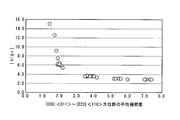
- which is an index of isotropy, be 3.5 or more. As shown in FIG.
- the average pole density of the ⁇ 011> to ⁇ 223 ⁇ ⁇ 110> orientation groups is 4.0 or less.
- the average pole density exceeds 4.0, the anisotropy becomes extremely strong.
- the average pole density is less than 1.0, there is a concern about the deterioration of the hole expansibility due to the deterioration of the local deformability.
- isotropy index 6.0 it is more desirable to set the average pole density of the ⁇ 100 ⁇ ⁇ 011> to ⁇ 223 ⁇ ⁇ 110> orientation groups to 2.0 or less.
- isotropy is 6.0 or more, even in the case where the variation in the coil is taken into consideration, it is possible to obtain plate thickness uniformity and roundness satisfying the component characteristics with sufficient processing as it is.
- the average pole density of ⁇ 100 ⁇ ⁇ 011> to ⁇ 223 ⁇ ⁇ 110> orientation groups is ⁇ 100 ⁇ ⁇ 011>, ⁇ 116 ⁇ ⁇ 110>, ⁇ 114 ⁇ ⁇ 110>, ⁇ 112 ⁇ ⁇ It is an azimuth group represented by arithmetic mean of each azimuth of 110> and ⁇ 223 ⁇ ⁇ 110>.
- the pole density of each direction of ⁇ 100 ⁇ ⁇ 011>, ⁇ 116 ⁇ ⁇ 110>, ⁇ 114 ⁇ ⁇ 110>, ⁇ 112 ⁇ ⁇ 110>, ⁇ 223 ⁇ ⁇ 110> is arithmetically averaged to obtain
- the average pole density of ⁇ 100 ⁇ ⁇ 011> to ⁇ 223 ⁇ ⁇ 110> orientation groups can be obtained.
- the above-mentioned isotropy index is processed into No. 5 test pieces described in JIS Z 2201 and determined according to the test method described in JIS Z 2241.
- means the plastic strain ratio (r value) in the rolling direction, 45 ° direction and 90 ° direction (sheet width direction) with respect to the rolling direction as r0, r45, r90, respectively
- ⁇ r (r0 ⁇ 2 ⁇ r45 + r90) / 2 is defined.
- the pole density of each direction is measured using a method such as EBSP (Electron Back Scattering Diffraction Pattern).
- EBSP Electro Back Scattering Diffraction Pattern
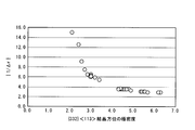
- in order to set the isotropic index 1 /
- the pole density of the crystal orientation of ⁇ 332 ⁇ ⁇ 113> in a central portion with a certain thickness is 4.8 or less.
- the pole density exceeds 4.8, the anisotropy becomes extremely strong.
- the pole density is less than 1.0, there is a concern about the deterioration of the hole expansibility due to the deterioration of the local deformability.
- the pole density of the crystal orientation of ⁇ 332 ⁇ ⁇ 113> is 3.0 or less.
- the value of the isotropy index is 6.0 or more, it is more desirable because even thickness uniformity and roundness satisfying component characteristics can be obtained with sufficient processing as it is even in consideration of variations in the coil.
- the average pole density of the above ⁇ 100 ⁇ ⁇ 011> to ⁇ 223 ⁇ ⁇ 110> orientation groups and the pole density of the crystal orientation of ⁇ 332 ⁇ ⁇ 113> are those of crystal grains intentionally directed to a certain crystal orientation. If the ratio is made higher than other orientations, the value will be higher.
- workability such as hole expansibility, will improve.
- the hole expansibility is preferably 70% or more.
- the above-mentioned pole density is synonymous with X-ray random intensity ratio.
- the X-ray random intensity ratio is the X-ray intensity of the sample obtained by measuring the X-ray intensities of the standard sample and the test material without accumulation in a specific orientation under the same conditions by X-ray diffraction method or the like. Divided by the X-ray intensity of the standard sample.
- the pole density can be measured by any of X-ray diffraction, EBSP method, or ECP (Electron Channeling Pattern) method.
- pole densities of ⁇ 100 ⁇ ⁇ 011> to ⁇ 223 ⁇ ⁇ 110> orientation groups are a plurality of ⁇ 110 ⁇ , ⁇ 100 ⁇ , ⁇ 211 ⁇ , ⁇ 310 ⁇ pole figures measured by these methods.
- the sample to be subjected to EBSP etc. has a steel plate thinner than the surface to a predetermined thickness by mechanical polishing or the like.
- the strain is removed by chemical polishing, electrolytic polishing, etc., and at the same time, the sample is adjusted and measured according to the above-mentioned method so that the appropriate surface becomes the measurement surface within the range of 5/8 to 3/8 of the plate thickness. Just do it.
- the sheet width direction it is desirable to collect at a position of 1 ⁇ 4 or 3 ⁇ 4 from the end of the steel plate.
- these pole densities do not change before and after gas soft nitriding treatment.
- the local deformability is further improved by satisfying the above-mentioned limitation of the pole density not only at the central portion of the plate thickness but also for as much thickness as possible.
- the azimuthal accumulation at a thickness of 3/8 to 5/8 from the surface of the steel sheet most strongly affects the product anisotropy, so in the thickness range of 5/8 to 3/8 from the surface of the steel sheet By measuring a certain thickness center portion, it is possible to generally represent the material characteristics of the entire steel plate.
- the polar density of the crystal orientation of> shall be defined.
- ⁇ hkl ⁇ ⁇ uvw> means that when the sample is taken by the above-mentioned method, the normal direction of the plate surface is parallel to ⁇ hkl ⁇ and the rolling direction is parallel to ⁇ uvw>. There is.
- the crystal orientation is usually expressed as [hkl] or ⁇ hkl ⁇ in the direction perpendicular to the plate surface, and (uvw) or ⁇ uvw> in the direction parallel to the rolling direction.
- ⁇ Hkl ⁇ , ⁇ uvw> is a generic term for equivalent planes, and [hkl], (uvw) refer to individual crystal planes.
- the present embodiment is directed to a body-centered cubic structure, for example, (111), (-111), (1-11), (11-1), (-1-11), (-11) 1), (1-1-1), and (-1-1-1) planes are equivalent and indistinguishable.
- these orientations are collectively referred to as ⁇ 111 ⁇ .
- the individual orientations are generally represented by [hkl] (uvw) because they are also used to indicate orientations of other low-symmetry crystal structures, but in the present embodiment, [hkl] ( uvw) and ⁇ hkl ⁇ ⁇ uvw> are synonymous.
- the vTrs of the original plate and the vTrs after nitriding treatment become lower in temperature as the average grain size becomes finer, that is, the toughness improves. Furthermore, vTrs after the nitriding treatment is affected by pearlite fraction and the like in addition to the average crystal grain size.
- the heat-rolled steel plate according to the present embodiment has the component range described in the present embodiment, when the vTrs after the nitriding treatment is ⁇ 20 ° C.
- the impact resistance is largely affected by the average grain size at the center of the plate thickness of the structure.
- the measurement of the average grain size at the center of the plate thickness was performed as follows. A micro sample was cut out from near the center in the thickness direction of the steel plate, and the grain size was measured using EBSP-OIM (registered trademark) (Electron Back Scatter Diffraction Pattern-Orientation Image Microscopy). The micro sample was polished with a colloidal silica abrasive for 30 to 60 minutes, and EBSP measurement was performed under the measurement conditions of a magnification of 400, a 160 ⁇ m ⁇ 256 ⁇ m area, and a measurement step of 0.5 ⁇ m.
- the EBSP-OIM (registered trademark) method irradiates an electron beam to a highly inclined sample in a scanning electron microscope (SEM), captures a Kikuchi pattern formed by back scattering with a high sensitivity camera, and performs computer image processing Therefore, the crystal orientation of the irradiation point is measured at short intervals.
- the microstructure and crystal orientation of the bulk sample surface can be analyzed quantitatively, and the analysis area is an area that can be observed with the SEM, and the analysis can be performed with a resolution of at least 20 nm depending on the resolution of the SEM.
- the analysis takes several hours, and the area to be analyzed is mapped to tens of thousands of points in a grid form at equal intervals. In polycrystalline materials, it is possible to see the distribution of crystal orientation and the size of crystal grains in a sample.
- a grain boundary is defined as a grain boundary by defining 15 °, which is a threshold value of a high angle grain boundary generally recognized as a grain boundary in the misorientation of the crystal grain, to visualize the grain from the mapped image.
- the average grain size was determined. That is, the "average grain size" is a value obtained by EBSP-OIM (registered trademark).
- the inventors have clarified each requirement for obtaining isotropy and impact resistance. That is, the average grain size directly related to the impact resistance becomes finer as the finish rolling end temperature is lower.
- the density and the polar density of the crystal orientation of ⁇ 332 ⁇ ⁇ 113> show an inverse correlation with the average grain size with respect to the finish rolling temperature. Therefore, a technique for achieving this isotropy and impact resistance has not been shown at all.
- the present inventors sufficiently recrystallize austenite after finish rolling for isotropy, and simultaneously minimize ist growth of recrystallized grains to simultaneously improve isotropy and impact resistance.
- the hot rolling method and conditions were explored.
- the temperature determined by the steel plate component represented by the above-mentioned formula (b) is T1 (° C.), and hot rolling is performed for the total rolling reduction R in the temperature range of T1 + 30 ° C. or more and T1 + 200 ° C. or less.
- the relationship between the end of rolling and the waiting time t seconds until the cooling temperature change is 40 ° C. or more and 140 ° C. or less and the cooling end temperature is T1 + 100 ° C. or less at a cooling rate of 50 ° C./sec or more.
- the ⁇ 100 ⁇ ⁇ 011> to ⁇ 223 ⁇ ⁇ 110> orientation at the center of the plate thickness which is the thickness range of 5/8 to 3/8 from the surface of the steel sheet in the texture of the steel sheet
- the average pole density of the group and the average grain size at the center of the plate thickness were investigated, and all R values were 50% or more, and the total rolling reduction (total rolling reduction) was In the same way as the so-called cumulative rolling reduction Cumulative rolling reduction with respect to the inlet plate thickness before the first pass in rolling in each temperature range (inlet plate thickness before the first pass in rolling in each temperature range and each temperature Of the difference in exit plate thickness after the last pass in rolling in the range.
- the waiting time t until the cooling rate cooling is performed at 50 ° C./sec or more after the completion of the hot rolling of the total rolling reduction R in the temperature range of T1 + 30 ° C. or more and T1 + 200 ° C. or less is represented by the above formula (c)
- the cooling temperature change is 40 ° C to 140 ° C and the cooling end temperature is T1 + 100 ° C or less within t1 ⁇ 2.5 seconds
- Average pole density of ⁇ 100 ⁇ ⁇ 011> to ⁇ 223 ⁇ ⁇ 110> orientation group at a thickness central portion in a thickness range of 1/8 is 1.0 or more and 4.0 or less and ⁇ 332 ⁇ ⁇ 113>
- the pole density of the crystal orientation is 1.0 or more and 4.8 or less, and the average grain size at the center of the plate thickness is 10 ⁇ m or less.
- the waiting time t seconds it is preferable to set the waiting time t seconds to less than t1, and for the purpose of further improving isotropy ⁇ 100 ⁇ ⁇ 011> It has been found that it is desirable to set the waiting time t seconds to t1 or more and 2.5 ⁇ t1 or less when the average pole density of the ⁇ 223 ⁇ ⁇ 110> orientation group is set to 2.0 or less.
- the present inventors further applied to members requiring ductility and severe thickness uniformity, roundness and impact resistance after processing.
- the inventors have conducted intensive studies on suitable hot-rolled steel sheets for gas soft nitriding and their production methods. As a result, it came to think of the hot rolled steel sheet which consists of the following conditions, and its manufacturing method. The reasons for limitation of chemical components in the present embodiment will be described.
- C content [C]: more than 0.07 and 0.2% or less C is an element that greatly affects the strength of the base material and the pearlite fraction. However, it is also an element that forms iron-based carbides such as cementite (Fe 3 C), which is a starting point of cracking during hole expansion. If the content [C] of C is less than or equal to 0.07%, it is not possible to obtain the effect of improving the strength by strengthening the structure by the low temperature transformation formation phase. On the other hand, if the content is more than 0.2%, the central segregation becomes remarkable, and iron carbides such as cementite (Fe 3 C) which become the starting point of the secondary shear surface cracking at the time of punching increases. Spreadability is degraded. For this reason, the content [C] of C is limited to the range of more than 0.07% and 0.2% or less. When the balance with ductility is considered together with the improvement of strength, the content [C] of C is desirably 0.15% or less.
- Si content [Si] 0.001% or more and 2.5% or less Si is an element that contributes to the increase in strength of the base material. It also has a role as a deoxidizer for molten steel. The above effect is exhibited when the Si content [Si] is 0.001% or more, but the effect contributing to the increase in strength is saturated even if it exceeds 2.5%. In addition, it is an element that greatly affects the transformation point, and when Si content [Si] is less than 0.001% or more than 2.5%, there is a possibility that the formation of pearlite is suppressed. For this reason, the Si content [Si] is limited to the range of 0.001% to 2.5%.
- Si is added by more than 0.1% to suppress the precipitation of iron-based carbides such as cementite in the steel sheet structure as the content thereof increases. Contributes to the improvement of strength and the improvement of the hole spreading property. On the other hand, when the addition amount exceeds 1%, the effect of suppressing the precipitation of iron-based carbides is saturated. Therefore, the desirable range of the Si content [Si] is more than 0.1% and 1% or less.
- Mn content [Mn] 0.01% or more and 4% or less Mn is an element that contributes to strength improvement by solid solution strengthening and quenching strengthening. However, if the Mn content [Mn] is less than 0.01%, this effect can not be obtained. On the other hand, above 4%, this effect is saturated. In addition, it is an element that greatly affects the transformation point, and when the Mn content [Mn] is less than 0.01% or more than 4%, there is a possibility that the formation of pearlite is suppressed. Therefore, the Mn content [Mn] is limited to the range of 0.01% or more and 4.0% or less.
- Mn is an element which enlarges the austenite zone temperature to the low temperature side with the increase of the content, improves the hardenability, and facilitates the formation of the continuous cooling transformation structure excellent in the burring property. This effect is difficult to exhibit when the Mn content [Mn] is less than 1%, so it is desirable to add 1% or more.
- P is an impurity contained in hot metal and is an element which segregates in grain boundaries and decreases toughness with an increase in content. Therefore, the lower the P content, the better. If the content is more than 0.15%, the formability and the weldability are adversely affected, so the content is limited to 0.15% or less. In particular, in consideration of the hole expandability and the weldability, the P content is desirably 0.02% or less. It is difficult in operation to make P 0%, so 0% is not included.
- S content [S]: more than 0% and 0.03% or less S is an impurity contained in hot metal, and if the content is too large, it may lower the toughness or cause cracking during hot rolling Not only that, it is an element that forms an A-based inclusion that degrades the hole expansibility. Therefore, the content of S should be reduced as much as possible. However, if it is 0.03% or less, it is an acceptable range, so it is limited to 0.03% or less. However, the S content [S] in the case where a certain degree of hole expandability is required is preferably 0.01% or less, more preferably 0.005% or less. It is difficult in operation to make S 0%, so 0% is not included.
- Al content [Al] 0.001% or more and 2% or less Al is added by 0.001% or more for deoxidizing liquid steel in the refining process of steel.
- the upper limit is made 2%.
- too much addition of Al increases non-metallic inclusions and degrades ductility and toughness. Therefore, it is desirable that it is 0.06% or less from the viewpoint of ductility and toughness. More preferably, it is 0.04% or less.
- the Al content [Al] is more preferably 0.016% or more and 0.04% or less.
- Ti is precipitated as TiC after ferrite transformation, and is added to suppress grain growth of ⁇ -grains during cooling or after winding due to the pinning effect.
- Ti is precipitated and fixed as TiN, TiS or the like in the high temperature region of the austenite phase. Therefore, in order to secure Ti effective for pinning in the ⁇ phase, 0.005+ [N] ⁇ 48/14 + [S] ⁇ 48/32 or more is added.
- Ti content [Ti] is less than this value, chipping resistance and rolling fatigue resistance characteristics will be reduced after gas soft nitriding treatment, so even if the original plate shows sufficient mechanical properties, gas soft nitriding It is insufficient as a hot-rolled steel sheet for use.
- the above chemical elements are basic components (basic elements) of the steel in the present embodiment, and the basic elements are controlled (included or limited), and the chemical composition in which the balance is iron and unavoidable impurities is the content of the present embodiment. It is a basic composition. However, in addition to this basic component (in place of part of the remaining Fe), in the present embodiment, if necessary, Nb, Cu, Ni, Mo, V, Cr, Ca, Mg, REM, You may contain 1 type or 2 types or more of B. In addition, even if these selective elements are inevitably mixed in the steel (for example, an amount less than the lower limit of the amount of each selective element), the effects in the present embodiment are not impaired. Below, the reason for component limitation of each element is described.
- Nb, Cu, Ni, Mo, V, and Cr are elements having the effect of improving the strength of the hot-rolled steel sheet by precipitation strengthening or solid solution strengthening.
- the Nb content [Nb] is less than 0.005%
- the Cu content [Cu] is less than 0.02%
- the Ni content [Ni] is less than 0.01%
- the Mo content [Mo] is 0.
- the V content [V] is less than 0.01% and the Cr content [Cr] is less than 0.01%, the above effects can not be sufficiently obtained.
- Nb content [Nb] is more than 0.06%
- Cu content [Cu] is more than 1.2%
- Ni content is more than [Ni] 0.6%
- Mo content [Mo] is 1%
- the Nb content [Nb] is 0.005% or more and 0.06% or less
- the Cu content [Cu] is 0. 0.
- Ni content [Ni] is 0.01% or more and 0.6% or less
- Mo content [Mo] is 0.01% or more and 1% or less
- V content [V] It is desirable that 0.01% or more and 0.2% or less and the Cr content [Cr] be 0.01% or more and 2% or less.
- Mg, Ca and REM are elements that serve as a starting point of destruction, control the form of nonmetallic inclusions that cause deterioration of processability, and improve processability. All of Ca, REM and Mg do not exhibit the above effect at less than 0.0005% addition. In addition, even if the content of Mg [Mg] exceeds 0.01%, the content of Ca [Ca] exceeds 0.01%, and the content of REM [REM] exceeds 0.1%, the above effect is obtained. It is saturated and the economy is reduced.
- the Mg content [Mg] is 0.0005% or more and 0.01% or less
- the Ca content [Ca] is 0.0005% or more and 0.01% or less
- the REM content [REM] is 0.0005 or more. It is desirable to add an amount of less than 1%.
- B content [B]: 0.0002% or more and 0.002% or less B has an effect of being linked to N and improving the hardness in gas soft nitriding treatment after molding. However, the effect can not be obtained with the addition of less than 0.0002%. On the other hand, even if it is added in excess of 0.002%, the effect is saturated. Furthermore, since it is an element that suppresses the recrystallization of austenite in hot rolling, a large amount of addition may strengthen the ⁇ ⁇ ⁇ transformation texture from unrecrystallized austenite and deteriorate the isotropy. Therefore, the content [B] of B is set to 0.0002% or more and 0.002% or less. On the other hand, from the viewpoint of slab cracking in the cooling step after continuous casting, [B] is preferably 0.0015% or less. That is, the B content [B] is more preferably 0.001% or more and 0.0015% or less.
- the heat-rolled steel plate which has these as a main component, you may contain Zr, Sn, Co, Zn, and W 1% or less in total as an unavoidable impurity.
- Sn is preferably 0.05% or less because of the possibility of generating wrinkles during hot rolling.
- the microstructure of the heat-rolled steel plate according to the present embodiment is composed of pearlite with a structural fraction of more than 6% and the balance of ferrite.
- the definition of the structure composition relates to toughness after nitriding, that is, impact resistance when used as a part after gas nitrocarburizing.
- the gas soft nitriding is performed at a relatively low temperature of around 570 ° C., which is below the ⁇ ⁇ ⁇ transformation point temperature. That is, unlike the quenching treatment, the gas nitrocarburizing treatment is not a tempering structure strengthening by phase transformation, but is a treatment which is significantly cured by producing a nitride having a high hardness.
- a compound layer white layer: ⁇ nitride Fe 2-3 N
- a diffusion layer with a thickness of about 100 to 300 ⁇ m in the deep part It can confirm. Furthermore, there is a matrix structure almost unchanged from before treatment at the deep part.
- the compound layer is an embrittled layer, and if it is too deep, the toughness after nitriding may be reduced.
- an average Vickers hardness Hv (0.005 kgf) of 0 to 5 ⁇ m from the surface of the gas soft nitrided compound layer satisfies chipping resistance and rolling fatigue resistance characteristics in parts subjected to gas soft nitriding treatment. It is required that the hardness be 350 Hv or more. More preferably, it is 400 Hv or more from the viewpoint of wear resistance.
- the upper limit of the structure fraction of pearlite is not particularly defined.
- the component range of the hot rolled steel sheet according to the present embodiment is a range to be hypoeutectoid steel, 25% is the upper limit.
- the lamellar spacing of perlite is not particularly limited. However, if it is more than 2 ⁇ m, the concentration of C present in the iron lattice of ferrite present in the form of being sandwiched by cementite trauma may decrease, and the effect of suppressing the diffusion of N may decrease. Therefore, the lamellar spacing of perlite is preferably 2 ⁇ m or less. More preferably, it is 1.5 ⁇ m or less, still more preferably 1.0 ⁇ m or less.
- the measurement of lamellar spacing was performed as follows. After etching with a nital, observation was made with a SEM at a magnification of 5000 or more and at least 5 fields of view, and the lamellar spacing of the perlite structure was measured.
- the lamellar spacing in the present embodiment indicates the average value thereof.
- the manufacturing method according to the present embodiment steel slabs, such as a slab which has the component mentioned above prior to the hot rolling process, are manufactured.
- the manufacturing method of this billet is not particularly limited. That is, as a method of manufacturing steel slabs having the above-described components, following the melting step using a blast furnace, a converter, an electric furnace, etc., the components are adjusted so as to have the target component content in various secondary refining steps, Then, the casting process may be performed by a method such as thin slab casting other than casting by normal continuous casting or ingot method.
- the high temperature slab may be sent to a hot rolling mill as it is, or it may be cooled once to room temperature and then reheated in a heating furnace and then hot rolled. You may use scrap as a raw material.
- the slab obtained by the above-described manufacturing method is heated in the slab heating step before the hot rolling step.
- the heating temperature is not particularly limited in the manufacturing method according to the present embodiment. However, if the heating temperature is more than 1260 ° C., the yield is reduced due to scale-off, so the heating temperature is preferably 1260 ° C. or less. Further, if the heating temperature is less than 1150 ° C., it is desirable that the heating temperature be 1150 ° C. or more, because the operation efficiency on schedule is significantly impaired.
- the heating time in the slab heating step is not particularly limited. However, from the viewpoint of avoiding center segregation and the like, it is desirable to maintain the heating temperature for 30 minutes or more after reaching the above-described heating temperature. However, this is not the case in the case where the cast slab after casting is subjected to high temperature direct rolling for rolling.
- the rough rolling step of performing rough rolling (first hot rolling) on the slab extracted from the heating furnace within, for example, 5 minutes is started without waiting, in particular, to obtain a rough bar.
- first hot rolling a reduction of 40% or more is performed once or more in a temperature range of 1000 ° C. or more and 1200 ° C. or less for the reason described below. If the rough rolling temperature is less than 1000 ° C., the hot deformation resistance in the rough rolling may be increased, which may disturb the rough rolling operation. On the other hand, if the rough rolling temperature is higher than 1200 ° C., the average grain size becomes large, which causes the toughness to be reduced.
- the secondary scale formed during rough rolling may grow too much, which may make it difficult to remove the scale in later de-scaling or finish rolling.
- the rough rolling end temperature is higher than 1150 ° C., the inclusions may be drawn to cause deterioration of the hole expansibility. Therefore, the temperature is desirably 1150 ° C. or less.
- the average crystal grain size becomes large, which causes a decrease in toughness.
- the grain size is more uniform and finer.
- it exceeds 65% the inclusions may cause stretching to deteriorate the hole expansibility. Therefore, it is desirable to set the upper limit to 65%.
- the austenite grain size after rough rolling that is, before finish rolling (second hot rolling) is important. Therefore, it is desirable to set the austenite grain size to 200 ⁇ m or less. By reducing austenite grains before finish rolling, grain refinement and homogenization of the heat rolled steel sheet are greatly promoted. In order to make the austenite grain size 200 ⁇ m or less, one or more reductions are performed at 40% or more. In order to obtain the effect of the grain refinement and homogenization more efficiently, it is more desirable that the austenite grain size be 100 ⁇ m or less. For this purpose, it is preferable to perform a reduction of 40% or more twice or more in rough rolling (first hot rolling). However, if the pressure is reduced more than 10 times, there is a concern that the temperature may decrease or scale may be overproduced.
- reducing the austenite grain size before finish rolling is effective for promoting recrystallization of austenite in subsequent finish rolling. This is presumed to be due to the function of austenite grain boundaries after rough rolling (that is, before finish rolling) as one of recrystallization nuclei during finish rolling. In this way, it is effective to finely control the average grain size of the steel sheet by appropriately controlling the time until finish of rolling, cooling start and the like as described later after reducing the austenite grain size.
- austenite grain boundaries are raised by etching and measured with an optical microscope. At this time, 20 or more fields of view are measured at a magnification of 50 or more by image analysis or a cutting method.
- the rough bar obtained after completion of the rough rolling process is joined between the rough rolling process and the finish rolling process, Endless rolling may be performed so as to perform rolling continuously.
- the rough bar may be wound once in a coil shape, stored in a cover having a heat retaining function, if necessary, rewound, and then joined.
- the rolling direction of the rough bar may be controlled by a heating device capable of controlling temperature variations in the thickness direction.
- heating means various heating means such as gas heating, electric heating, induction heating, etc. can be considered, but it is possible to control the variation in temperature in the rolling direction, width direction and thickness direction of the rough bar small. Any known means may be used.
- the induction heating system which has good control response of temperature industrially is preferable.
- the temperature distribution in the plate width direction can be arbitrarily controlled according to the plate width, which is more preferable.
- the system of the heating device is most preferably a device constituted by a combination of a transverse induction heating device and a solenoid induction heating device which is excellent in heating the entire plate width.
- the control of the heating amount by the induction heating device is controlled, for example, as follows.
- a characteristic of the induction heating device transverse induction heating device
- a magnetic field is generated inside the coil.
- an eddy current in the direction opposite to the coil current occurs in the circumferential direction perpendicular to the magnetic flux by electromagnetic induction, and the conductor is heated by the Joule heat. Eddy current is most strongly generated on the surface inside the coil and decreases exponentially inside (this phenomenon is called skin effect).
- the current penetration depth decreases as the frequency increases, and a small heating pattern of overheating with the surface layer peaking in the thickness direction can be obtained. Therefore, heating in the rolling direction and the sheet width direction of the rough bar can be performed in the same manner as in the prior art by the transverse induction heating device.
- the heating in the thickness direction can change the penetration depth by changing the frequency of the transverse induction heating device, and the temperature distribution can be made uniform by operating the heating pattern in the thickness direction.
- the frequency may be changed by adjusting a capacitor.
- the control of the heating amount by the induction heating device may change the distribution of each heating amount so as to obtain a required thickness direction heating pattern by arranging a plurality of inductors having different frequencies.
- the control of the amount of heating by the induction heating device fluctuates in frequency when the air gap with the material to be heated is changed. Therefore, the air gap may be changed to obtain a desired frequency and heating pattern.
- the fatigue strength of a hot-rolled or pickled steel sheet correlates with the maximum height Ry of the steel sheet surface. Therefore, it is desirable that the maximum height Ry (corresponding to Rz defined in JIS B 0601: 2001) of the steel plate surface after finish rolling be 15 ⁇ m (15 ⁇ m Ry, l2.5 mm, ln 12.5 mm) or less. In order to obtain this surface roughness, it is desirable that the conditions of the collision pressure P of high pressure water on the steel sheet surface ⁇ flow rate L ⁇ 0.003 be satisfied in descaling. Subsequent finish rolling is preferably performed within 5 seconds after descaling to prevent scale formation again.
- the finish rolling (second hot rolling) process is started.
- the time from the end of rough rolling to the start of finish rolling is 150 seconds or less. If the time from the end of rough rolling to the start of finish rolling is more than 150 seconds, the average grain size in the steel sheet becomes large and the toughness is lowered.
- the lower limit is not particularly limited, but is preferably 5 seconds or more when recrystallization is completely completed after rough rolling. In the case where there is a concern about the influence on the material due to temperature decrease of the surface of the rough bar due to roll contact and uneven temperature in the thickness direction of the rough bar due to heat generation, it is desirable to be 20 seconds or more.
- the finish rolling start temperature is set to 1000 ° C. or more. If the finish rolling start temperature is less than 1000 ° C., the rolling temperature given to the rough bar to be rolled in each finish rolling pass becomes lower, and the rolling becomes a pressure in the non-recrystallization temperature range, the texture develops and the isotropy deteriorates. Do.
- the upper limit of the finish rolling start temperature is not particularly specified. However, if the temperature is 1150 ° C. or higher, there is a risk that blisters, which are origins of scale-like spindle scale defects, may occur between the steel sheet steel and the surface scale before finish rolling and between passes. Therefore, the finish rolling start temperature is desirably less than 1150 ° C.
- T1 a temperature calculated by the following formula (b) using the content of each element.
- T1 850 + 10 x ([C] + [N]) x [Mn] + 350 x [Nb] + 250 x [Ti] + 40 x [B] + 10 x [Cr] + 100 x [Mo] + 100 x [V] ...
- the total rolling reduction in the temperature range of T1 + 30 ° C. or more and T1 + 200 ° C. or less is less than 50%, the rolling strain accumulated during hot rolling is not sufficient and the austenite recrystallization does not sufficiently proceed, so the grain size is Coarseness is developed, and the texture is developed and the isotropy is degraded. Therefore, the total rolling reduction in finish rolling is 50% or more. Desirably, if the total rolling reduction is 70% or more, sufficient isotropy can be obtained even in consideration of variations due to temperature fluctuations and the like. On the other hand, if the total rolling reduction exceeds 90%, it becomes difficult to maintain the temperature range of T1 + 200 ° C. or less due to processing heat and the like, which is not desirable.
- the sum of the rolling reductions at T1 + 30 ° C. or more and T1 + 200 ° C. or more is 50% or more, and at least one pass 30% or more during this rolling. Reduce pressure.
- the total rolling reduction in rolling at a temperature above the Ar3 transformation point temperature and below T1 + 30 ° C. is limited to 30% or less. From the viewpoint of plate thickness accuracy and plate shape, a rolling reduction of 10% or less is desirable, but when finding more isotropy, the rolling reduction is more preferably 0%.
- All of the first to third hot rolling need to be completed at or above the Ar3 transformation temperature.
- hot rolling below the Ar3 transformation temperature two-phase rolling is performed, and isotropy and ductility decrease due to the remaining of the processed ferrite structure.
- the end temperature of rolling is T1 ° C. or higher.
- the cooling temperature change is 40 ° C or more and 140 ° C or less
- the cooling stop temperature is T1 + 100 ° C or less so that the waiting time t seconds from completion to the start of cooling satisfies the following formula (c). Primary cooling.
- the waiting time t until cooling is more than 2.5 ⁇ t 1 seconds, so the recrystallized austenite grains are maintained at a high temperature, so crystal grains grow remarkably, and as a result, the toughness deteriorates.
- the primary cooling in order to water-cool a steel plate as quickly as possible after rolling, it is desirable to cool between rolling stands.
- instrumentation devices such as thermometers and plate thickness gauges are installed on the rear face of the final rolling stand, measurement is difficult due to steam or the like generated when cooling water is applied, so the final rolling stand It is difficult to install a cooling device immediately after.
- t1 0.001 ⁇ ((Tf ⁇ T1) ⁇ P1 / 100) 2 ⁇ 0.109 ⁇ ((Tf ⁇ T1) ⁇ P1 / 100) +3.1 (d)
- Tf is the temperature (° C.) after the final pass reduction of the large reduction pass
- P1 is the reduction ratio (%) of the final pass of the large reduction pass.
- the primary cooling may be performed earlier than the third hot rolling as long as the waiting time until the start of the cooling is as described above.
- the cooling stop temperature becomes equal to or lower than the Ar3 transformation temperature
- a bainitic structure may be generated, and the formation of ferrite and pearlite may be suppressed.
- the cooling rate in this cooling is less than 50 ° C./sec, the recrystallized austenite grains grow and the toughness deteriorates.
- the upper limit of the cooling rate is not particularly defined, but 200 ° C./sec or less seems appropriate from the viewpoint of plate shape.
- the steel plate temperature at the end of cooling exceeds T1 + 100 ° C, the effect of cooling can not be obtained sufficiently. Even if primary cooling is carried out under the proper conditions after the final pass, grain growth may occur if the steel sheet temperature after primary cooling is over T1 + 100 ° C., and there is a concern that the austenite grain size may become coarse. It is for.
- the temperature rise between finish rolling passes be 18 ° C. or less.
- an inter-pass cooling device can be used.
- Whether or not the above-described defined rolling is being performed can be determined by actual results or calculation from the rolling load, plate thickness measurement, etc. for the rolling ratio. Also, the temperature can be measured if there is a stand-to-stand thermometer, or it can be obtained by either or both of them because it is possible to perform calculation simulation considering processing heat generation etc. from the line speed and rolling reduction etc. .
- the rolling speed is not particularly limited, but if the rolling speed on the final finishing stand side is less than 400 mpm, there is a tendency for the ⁇ grains to grow and coarse. Therefore, the area where ferrite can be deposited for obtaining ductility is reduced, and the ductility may be deteriorated.
- the upper limit can be obtained without particular limitation, the effect can be obtained, but due to equipment limitations, 1800 mpm or less is realistic. Therefore, it is desirable to set the rolling speed in the finish rolling process to 400 mpm or more and 1,800 mpm or less as necessary.
- secondary cooling may be performed after passing through the rolling stand before the winding process.
- the cooling pattern is not particularly limited, and may be appropriately set in accordance with the line speed and the winding temperature as long as the winding temperature described later can be satisfied.
- the winding temperature is set to be over 550 ° C. If the temperature is 550 ° C. or lower, the temperature becomes lower than the Bs point, and bainite is mixed into the microstructure, which may deteriorate the impact resistance after the nitriding treatment. Also, pearlite transformation does not proceed sufficiently after winding.
- the upper limit of the coiling temperature is not particularly defined, it does not become higher than the rolling end temperature. If the temperature is higher than 850 ° C., the surface properties of the steel sheet may be deteriorated by oxidation of the outermost periphery of the coil, so 850 ° C. or less is desirable. More desirably, the temperature is 800 ° C. or less.
- the lamellar spacing of the perlite structure is 2 ⁇ m or less, it is desirable to set the winding temperature to 800 ° C. or less. When the thickness is 1.5 ⁇ m or less, it is more preferable to set the temperature to 700 ° C. or less.
- the pearlite structure is mainly generated in the winding process, and the lamellar spacing of pearlite is greatly influenced by the diffusion distance of Fe and C.
- skin pass rolling with a rolling reduction of 0.1% or more and 2% or less may be performed after completion of all steps for the purpose of improving ductility by correcting the shape of the steel sheet and introducing movable dislocations.
- the hot rolled steel sheet obtained as necessary may be pickled for the purpose of removing the scale adhering to the surface of the obtained hot rolled steel sheet.
- skin pass or cold rolling with a rolling reduction of 10% or less may be performed on the obtained hot rolled steel sheet in line or off line.
- the heat-rolled steel plate according to the present embodiment may be subjected to heat treatment in a hot-dip plating line in any case after casting, after hot-rolling, and after cooling, and further, these heat-rolled steel plates are separately surfaced. Processing may be performed.
- the corrosion resistance of the hot rolled steel sheet is improved.
- the hot-rolled steel plate after pickling is subjected to zinc plating
- the obtained steel plate may be immersed in a zinc plating bath and alloyed as needed.
- the hot rolled steel sheet is improved in the welding resistance to various types of welding such as spot welding, in addition to the improvement of the corrosion resistance.
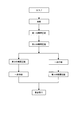
- FIG. 3 shows a flowchart showing an outline of the manufacturing method according to the present embodiment.
- a nitriding treatment component can be obtained by performing gas soft nitriding on the obtained hot-rolled steel sheet.
- Ar3 transformation point temperature refers to an Ar3 temperature (° C.) calculated by the following formula (g): “T1” refers to the temperature calculated by the equation (b), and “t1” refers to the time calculated by the equation (d).
- Ar3 910-310 x [C] + 25 x [Si]-80 x [Mneq] ... (g)
- [Mneq] is represented by the formula (h) when B is not added, and by the following formula (i) when B is added.
- [Mneq] [Mn] + [Cr] + [Cu] + [Mo] + [Ni] / 2 + 10 ⁇ ([Nb] -0.02) (h)
- [Mneq] [Mn] + [Cr] + [Cu] + [Mo] + [Ni] / 2 + 10 ⁇ ([Nb] -0.02) +1 (i)
- [component element] is the content of the component element represented by mass%.
- Heating temperature refers to the heating temperature in the slab heating step
- holding time refers to the holding time at the predetermined heating temperature in the heating step
- number of reductions of 1000 ° C. to 40% or more and “1000 ° C. or more
- the rolling reduction rate of 40% or more pass in the temperature range of 1000 ° C. or more and 1200 ° C. or less in rough rolling and the “time until start of finish rolling” are rough rolling process
- total rolling reduction means the total rolling reduction in hot rolling in each temperature range.
- Tf is the temperature after the final pass reduction of the large reduction pass
- P1 is the reduction ratio of the final pass of the large reduction pass
- the maximum temperature increase between passes is T1 + 30 ° C. or more and T1 + 200 ° C. or less
- waiting time until the start of primary cooling refers to the final reduction step among the large reduction paths when the reduction ratio path of 30% or more in the temperature range of T1 + 30 ° C. or more and T1 + 200 ° C.
- the waiting time from completion to the start of cooling refers to the average cooling rate from the start of primary cooling temperature to the completion of primary cooling
- “change in primary cooling temperature” refers to the primary cooling start temperature and end temperature
- rolling temperature indicates the temperature at which the coiler winds up in the winding process.
- Tables 8 to 10 show the evaluation results of the obtained steel plates.
- mechanical properties tensile properties, isotropy and hole expansibility were evaluated on the original plate, and toughness was evaluated on both the original plate and the hot-rolled steel plate after nitriding treatment.
- toughness was evaluated on both the original plate and the hot-rolled steel plate after nitriding treatment.
- average hardness Hv (0.005 kgf)
- the “perlite fraction” refers to the area fraction of the pearlite structure measured by the point count method from the optical microscope structure
- the “average grain size” refers to the average crystal grain size measured by EBSP-OIMTM.
- “Average pole density of ⁇ 100 ⁇ ⁇ 011> to ⁇ 223 ⁇ ⁇ 110> orientation group” means pole density of ⁇ 100 ⁇ ⁇ 011> to ⁇ 223 ⁇ ⁇ 110> orientation group parallel to the rolling surface
- the polar density of the crystal orientation of ⁇ 332> ⁇ 113> refers to the polar density of the crystal orientation of ⁇ 332> ⁇ 113> parallel to the rolling surface
- the term “compound layer depth after gas soft nitriding” refers to ammonia gas + N 2
- a compound layer (white layer: ⁇ -nitride Fe 2) obtained by gas cross-section micro sample collection from the surface layer after performing gas soft nitriding treatment by heating and holding for 5 hours in a + CO 2 atmosphere at 560 to 580 ° C.
- the "tensile test” result shows the result of the C direction JIS No. 5 test piece.
- YP indicates a yield point
- TS indicates tensile strength
- El indicates elongation.
- isotropic refers to the reciprocal of
- the "hole spreading” results showed the results obtained with the hole spreading test method described in JFS T 1001: 1996.
- Toughness indicates the transition temperature (vTrs) obtained in the subsize V-notch Charpy test.
- These steel plates contain a predetermined amount of steel components, and the ⁇ 100 ⁇ ⁇ 011> to ⁇ 223 in the central portion of the plate thickness range of 5/8 to 3/8 from the surface of the steel plate in the texture of the steel plate.
- the average pole density of the ⁇ 110> orientation group is 1.0 or more and 4.0 or less, and the pole density of the crystal orientation of ⁇ 332 ⁇ ⁇ 113> is 1.0 or more and 4.8 or less, and further at the plate thickness center It is a hot rolled steel sheet for gas soft nitriding having a tensile strength of 440 MPa or more characterized by an average crystal grain size of 10 ⁇ m or less, and a microstructure having a microstructure fraction of pearlite of more than 6% and the balance of ferrite.
- these hot rolled steel sheets exhibit excellent properties in isotropy, toughness after nitriding, toughness of the original plate, average hardness up to 5 ⁇ m from the surface of the compound layer after gas soft nitriding, and hole expandability. ing.
- the steel plate manufactured by the present invention is an internal plate member, a structural member, a foot member, a transmission, etc. which require high ductility and severe thickness uniformity after processing, roundness and impact resistance while having high strength. It can be used for all applications such as shipbuilding, construction, bridges, offshore structures, pressure vessels, line pipes, machine parts, etc., including automobile parts. For this reason, the present invention has high industrial value.
Landscapes
- Chemical & Material Sciences (AREA)
- Engineering & Computer Science (AREA)
- Mechanical Engineering (AREA)
- Materials Engineering (AREA)
- Metallurgy (AREA)
- Organic Chemistry (AREA)
- Physics & Mathematics (AREA)
- Thermal Sciences (AREA)
- Crystallography & Structural Chemistry (AREA)
- Heat Treatment Of Sheet Steel (AREA)
- Heat Treatment Of Steel (AREA)
Abstract
Description
すなわち、上記部品を始めとする板厚の均一性が求められる部品用の薄鋼板には、優れた加工性に加えて、塑性的な等方性と耐衝撃性(靭性)とを両立させることが求められている。
しかしながら、特許文献1に開示される技術を適用して製造される鋼板は、塑性等方性については何ら言及されていない。そのため、例えば歯車などの真円度や円周方向の板厚の均質性が求められる部品に適用することを前提にすると部品の偏心による不正な振動やフリクションロスによる出力の低下が懸念される。
しかしながら、上述した特許文献2、3に開示された技術を適用した鋼板は、高価な合金元素であるMoを0.07%以上添加することを必須としているため製造コストが高いという問題点がある。更に、特許文献2及び3に開示の技術においては、塑性等方性について何ら言及されていない。そのため、真円度や円周方向の板厚の均質性が求められる部品に適用することを前提にすると、部品の偏心による不正な振動やフリクションロスによる出力の低下が懸念される。
しかしながら、このような摩擦係数の小さい潤滑圧延をコイル全長にわたって実施するためには圧延中のロールバイトと圧延材とのスリップによる噛み込み不良を防止するためにエンドレス圧延が必要である。そのため、この技術を適用するためには粗バー接合装置や高速クロップシャー等の設備投資が伴うため負担が大きい。
しかしながら、高価な合金元素であるMoを0.1%以上添加することを必須としているため、製造コストが高いという問題点がある。
0.005+[N]×48/14+[S]×48/32≦Ti≦0.015+[N]×48/14+[S]×48/32・・・(a)
0.005+[N]×48/14+[S]×48/32≦Ti≦0.015+[N]×48/14+[S]×48/32・・・(a)
T1=850+10×([C]+[N])×[Mn]+350×[Nb]+250×[Ti]+40×[B]+10×[Cr]+100×[Mo]+100×[V]・・・(b)
t≦2.5×t1・・・(c)
ここで、t1は下記式(d)で表される。
t1=0.001×((Tf-T1)×P1/100)2-0.109×((Tf-T1)×P1/100)+3.1・・・(d)
ここで、Tfは、大圧下パスの最終パス圧下後の温度(℃)、P1は、大圧下パスの最終パスの圧下率(%)である。
t1≦t≦2.5×t1・・・(e)
t<t1・・・(f)
なお、ガス軟窒化用熱延鋼板では、部品として使用される際にガス軟窒化処理が行われることを想定している。そのため、原板(ガス軟窒化処理を行っていない熱延鋼板)での靭性に加えて、ガス軟窒化処理後(単に窒化処理後と言う場合がある)でも、十分な耐衝撃性(靭性)を示すことが求められる。通常、ガス軟窒化処理後の熱延鋼板は、表層に生成する化合物相などの影響で、ガス軟窒化処理前の熱延鋼板に比べて耐衝撃性が劣化する。本実施形態に係る熱延鋼板では、原板の靭性を目標値以上とし、さらに、窒化層を制御することで、ガス軟窒化処理後の熱延鋼板の靭性についても目標値以上とすることを検討した。
なお、本実施形態において、単に耐衝撃性、または靭性と言う場合、原板、窒化処理後の両方の耐衝撃性、または靭性を示す。
検討の結果、以下の新たな知見を得た。
鋼板を真円度や円周方向の板厚の均質性が求められる部品に加工する場合、トリミングや切削の工程を省略し加工ままで部品特性を満足する板厚均一性、真円度を得るために、等方性の指標である等方性指標1/|Δr|が3.5以上であることが望ましい。図1に示すように、等方性指標を3.5以上とするために、鋼板の集合組織で鋼板の表面から5/8~3/8の板厚範囲である板厚中央部における{100}<011>~{223}<110>方位群の平均極密度は、4.0以下とする。この平均極密度が4.0超となると異方性が極めて強くなる。一方、この平均極密度が1.0未満になると局部変形能の劣化による穴広げ性の劣化が懸念される。さらに優れた等方性指標6.0を得るためには、{100}<011>~{223}<110>方位群の平均極密度を、2.0以下とすることがより望ましい。等方性が6.0以上の場合、コイル内でのバラツキを考慮した場合でも、十分に加工ままで部品特性を満足する板厚均一性、真円度が得られる。ここで、{100}<011>~{223}<110>方位群の平均極密度とは、{100}<011>、{116}<110>、{114}<110>、{112}<110>、{223}<110>の各方位の相加平均で表わされる方位群である。そのため、{100}<011>、{116}<110>、{114}<110>、{112}<110>、{223}<110>の各方位の極密度を相加平均することで、{100}<011>~{223}<110>方位群の平均極密度を得ることができる。
なお、上記の{100}<011>~{223}<110>方位群の平均極密度及び{332}<113>の結晶方位の極密度は、意図的にある結晶方位に向いた結晶粒の割合を他の方位よりも高めるようにした場合には、値が高くなる。
また、上記の平均極密度、極密度が低いと、穴広げ性などの加工性が向上する。なお、穴広げ性は、70%以上であることが望ましい。
原板のvTrs及び窒化処理後のvTrsは、平均結晶粒径が細粒であるほど低温化する、すなわち靭性が向上する。さらに、窒化処理後のvTrsは、平均結晶粒径の他に、パーライト分率などの影響を受ける。本実施形態に係る熱延鋼板では、窒化処理後のvTrsを、寒冷地で窒化処理部品として使用するのに耐え得る-20℃以下とする場合、本実施形態に記載した成分範囲を有し、パーライト分率が6%超である熱延鋼板において、板厚中心部での平均結晶粒径を10μm以下とすることが望ましいことが分かった。さらに、厳しい環境での使用を想定して窒化処理後のvTrsを-40℃以下とする場合、板厚中心部での平均結晶粒径を7μm以下とすることがより望ましい。
耐衝撃性(靭性)は、Vノッチシャルピー衝撃試験で得られるvTrs(シャルピー破面遷移温度)にて評価した。ここで、Vノッチシャルピー衝撃試験は、JIS Z 2202に基づいて試験片を作製し、これについてJIS Z 2242で規定される内容でシャルピー衝撃試験を行い、vTrsを測定した。
EBSP法ではバルク試料表面の微細構造並びに結晶方位を定量的に解析することができ、分析エリアはSEMで観察できる領域で、SEMの分解能にもよるが、最小20nmの分解能で分析できる。解析は数時間かけて、分析したい領域を等間隔のグリッド状に数万点マッピングして行う。多結晶材料では試料内の結晶方位分布や結晶粒の大きさを見ることができる。
すなわち、耐衝撃性に直接係わる平均結晶粒径は仕上げ圧延終了温度が低温ほど細粒になる。しかし、等方性の支配因子の一つである鋼板の表面から5/8~3/8の板厚範囲である板厚中央部における{100}<011>、{116}<110>、{114}<110>、{112}<110>、{223}<110>の各方位の極密度の相加平均で表わされる{100}<011>~{223}<110>方位群の平均極密度と、{332}<113>の結晶方位の極密度とは、仕上げ圧延温度に対して平均結晶粒径とは逆の相関を示す。そのため、この等方性と耐衝撃性を両立する技術はこれまで全く示されていなかった。
これは、等方性と耐衝撃性の両方を向上させ得る範囲、すなわち、十分なオーステナイトの再結晶と細粒化が両立する範囲が後程詳細に述べる本実施形態で規定する熱間圧延方法で達成可能であることを示している。
さらに、より靭性を向上させる目的で平均結晶粒径が7μm以下とする場合には、待ち時間t秒をt1未満とすることが望ましく、より等方性を向上させる目的で{100}<011>~{223}<110>方位群の平均極密度を2.0以下とする場合には、待ち時間t秒をt1以上2.5×t1以下とすることが望ましいことが分かった。
本実施形態における化学成分の限定理由について説明する。
Cは、母材の強度、パーライト分率に大きな影響を与える元素である。しかし、穴広げ時の割れの起点となるセメンタイト(Fe3C)等の鉄系炭化物を生成させる元素でもある。Cの含有量[C]が、0.07%以下では、低温変態生成相による組織強化による強度向上の効果を得ることが出来ない。一方、0.2%超含有していると中心偏析が顕著になり打ち抜き加工時に二次せん断面の割れの起点となるセメンタイト(Fe3C)等の鉄系炭化物が増加し、打ち抜き性や穴広げ性が劣化する。このため、Cの含有量[C]は、0.07%超0.2%以下の範囲に限定する。強度の向上とともに延性とのバランスを考慮する場合には、Cの含有量[C]は0.15%以下であることが望ましい。
Siは、母材の強度上昇に寄与する元素である。また、溶鋼の脱酸材としての役割も有する。Si含有量[Si]は、0.001%以上である場合に上記効果を発揮するが、2.5%を超えても強度上昇に寄与する効果が飽和する。また、変態点に大きく影響を及ぼす元素であり、Si含有量[Si]が、0.001%未満の場合や2.5%を超える場合には、パーライトの生成が抑制される虞がある。このため、Si含有量[Si]は、0.001%以上2.5%以下の範囲に限定する。なお、強度向上と穴広げ性の向上の観点からは、Siは、0.1%超添加することでその含有量の増加に伴い、鋼板組織中におけるセメンタイト等の鉄系炭化物の析出を抑制し、強度向上と穴広げ性の向上に寄与する。一方、添加量が1%を超えてしまうと鉄系炭化物の析出抑制の効果は飽和する。従って、Si含有量[Si]の望ましい範囲は、0.1%超1%以下である。
Mnは、固溶強化及び焼入れ強化により強度向上に寄与する元素である。しかし、Mn含有量[Mn]が、0.01%未満ではこの効果を得ることが出来ない。一方、4%超ではこの効果が飽和する。また、変態点に大きく影響を及ぼす元素であり、Mn含有量[Mn]が、0.01%未満の場合や4%を超える場合には、パーライトの生成が抑制される虞がある。このため、Mn含有量[Mn]は、0.01%以上4.0%以下の範囲に限定する。Sによる熱間割れの発生を抑制するためにMn以外の元素が十分に添加されない場合には、Mn含有量[Mn]とS含有量[S]が質量%で[Mn]/[S]≧20であることが望ましい。さらに、Mnは、その含有量の増加に伴いオーステナイト域温度を低温側に拡大させて焼入れ性を向上させ、バーリング性に優れる連続冷却変態組織の形成を容易にする元素である。この効果は、Mn含有量[Mn]が、1%未満では発揮しにくいので、1%以上添加することが望ましい。
Pは、溶銑に含まれている不純物であり、粒界に偏析し、含有量の増加に伴い靭性を低下させる元素である。このため、P含有量は、低いほど望ましい。0.15%超含有すると加工性や溶接性に悪影響を及ぼすので、0.15%以下に制限する。特に、穴広げ性や溶接性を考慮すると、P含有量は、0.02%以下であることが望ましい。Pを0%にするのは、操業上、困難であるので、0%は含まない。
Sは、溶銑に含まれている不純物であり、含有量が多すぎると、靭性を低下させたり、熱間圧延時の割れを引き起こしたりするばかりでなく、穴広げ性を劣化させるA系介在物を生成させる元素である。このためSの含有量は、極力低減させるべきである。しなしながら、0.03%以下ならば許容できる範囲であるので、0.03%以下に制限する。ただし、ある程度の穴広げ性を必要とする場合のS含有量[S]は、好ましくは0.01%以下、より好ましくは0.005%以下である。Sを0%にするのは、操業上、困難であるので、0%は含まない。
Alは、鋼の精錬工程における溶鋼脱酸のために0.001%以上添加する。しかし多量の添加は、コストの上昇を招くため、その上限を2%とする。また、Alをあまり多量に添加すると、非金属介在物を増大させ延性及び靭性を劣化させる。そのため延性及び靭性の観点からは0.06%以下であることが望ましい。更に望ましくは0.04%以下である。また、Siと同様に材料組織中におけるセメンタイト等の鉄系炭化物の析出を抑制する効果を得るためには、0.016%以上含有させることが望ましい。従って、Al含有量[Al]は、0.016%以上0.04%以下であることがさらに望ましい。
Nは、鋳造時にTiと粗大なTiNを生成し、ガス軟窒化時のTiによる表面硬度向上効果を低下させる。そのため、極力低減させるべきである。しかしながら、0.01%以下ならば許容できる範囲である。耐時効性の観点からは0.005%以下とすることが更に望ましい。Nを0%にするのは、操業上、困難であるので、0%は含まない。
Tiは、フェライト変態後にTiCとして析出させ、ピンニング効果により冷却中または巻き取り後のα粒の粒成長を抑制するために添加する。ただし、Tiは、オーステナイト相の高温域においてTiNおよびTiS等として析出固定されてしまう。そのため、α相においてピンニングに有効なTiを確保するために0.005+[N]×48/14+[S]×48/32以上添加する。一方、0.015+[N]×48/14+[S]×48/32超添加してもその効果は飽和するためにこれを上限とする。また、Tiは、TiCとしてCを固定するので、過度に添加すると、パーライトの生成が抑制される虞がある。
また、Tiは成形後のガス軟窒化処理においてNと結びつき硬度を高める効果がある。そのためには0.005+[N]×48/14+[S]×48/32以上添加する。Ti含有量[Ti]がこれ未満であると、ガス軟窒化処理後において、耐チッピング性、耐転動疲労特性が低下するため、原板では、十分な機械的特性を示しても、ガス軟窒化用熱延鋼板としては不十分である。
Bは、成形後のガス軟窒化処理においてNと結びつき硬度を高める効果がある。ただし、0.0002%未満の添加ではその効果が得られない。一方、0.002%を超えて添加してもその効果が飽和する。さらに、熱間圧延でのオーステナイトの再結晶を抑制する元素であるため、多量の添加は未再結晶オーステナイトからのγ→α変態集合組織を強め、等方性を劣化させる恐れがある。このため、Bの含有量[B]は、0.0002%以上0.002%以下とする。一方、連続鋳造後の冷却工程でスラブ割れの観点からは[B]は0.0015%以下が望ましい。すなわち、B含有量[B]は、0.001%以上0.0015%以下であることがより望ましい。
本実施形態に係る熱延鋼板のミクロ組織は、組織分率で6%超のパーライトと残部がフェライトからなる。この組織構成の規定は、窒化処理後の靭性、すなわち、ガス軟窒化処理後に部品として使用される際の耐衝撃性に関わる。
ガス軟窒化処理した材料の断面を顕微鏡で観察すると厚さ約10~20μmの化合物層(白層:ε窒化物Fe2-3N)及び、その深部に厚さ100~300μm程度の拡散層が確認できる。さらにその深部には処理前とほとんど変化のない母材組織が存在している。なお、上記化合物層は、脆化層であり、深すぎると窒化処理後の靭性を低下させる虞があるため、20μm以下が好ましい。
また、ガス軟窒化後化合物層の表面から0~5μmの平均ビッカース硬度Hv(0.005kgf)は、ガス軟窒化処理を施された部品において、耐チッピング性、耐転動疲労特性を満足するために、350Hv以上の硬度とすることが求められる。耐摩耗性の観点から、さらに望ましくは400Hv以上である。
2NH3 ←→ 2N+3H2
の反応で得られたNが鋼板表面より拡散して窒化物を作る。その際の鉄と窒素の化合物は、面心立方格子のγ‘相(Fe4N)と稠密六方格子のζ相(Fe2N)の2種類があり、N濃度が11%を超えるとζ相が生成する。このζ相は窒化処理後の靭性を極端に劣化させる。
本発明者らは、ζ相の生成をNの拡散を抑制することで可能な限り回避する方法について金属組織学的観点より鋭意研究を重ねた。その結果、ミクロ組織において、組織分率で6%超のパーライトが存在するとNの拡散が抑制されζ相の生成を回避できることを新たに知見した。
このメカニズムは明らかではないが、パーライト組織を形成しているバンド状のセメンタイトラメラーにサンドイッチされる形で存在するフェライトにおいてCが鉄格子中に多く存在し、ガス軟窒化処理で鉄格子中に拡散しようするNの侵入サイトを占有していることにより、Nの拡散が抑制されたためと考えられる。
本実施形態に係る熱延鋼板においてパーライトのラメラー間隔については特に限定しない。しかし、2μm超であるとセメンタイトラメラーにサンドイッチされる形で存在するフェライトの鉄格子中に存在するCの濃度が減少し、Nの拡散を抑制する効果が低下する可能性がある。そのため、パーライトのラメラー間隔は2μm以下が望ましい。より望ましくは1.5μm以下、さらに一層望ましくは1.0μm以下である。
本実施形態に係る製造方法において、熱間圧延工程に先行して上述した成分を有するスラブなどの鋼片を製造する。この鋼片の製造方法は特に限定されるものではない。すなわち、上述した成分を有する鋼片の製造方法としては、高炉、転炉や電炉等による溶製工程に引き続き、各種の二次精練工程で目的の成分含有量になるように成分調整を行い、次いで通常の連続鋳造、又はインゴット法による鋳造の他、薄スラブ鋳造などの方法で鋳造工程を行うようにしてもよい。また、連続鋳造によってスラブを得た場合には、高温鋳片のまま熱間圧延機に送ってもよく、一度室温まで冷却後に加熱炉にて再加熱した後に熱間圧延してもよい。原料にはスクラップを使用しても構わない。
スラブ加熱工程における加熱時間については特に限定しない。しかし、中心偏析等を回避する観点からは、上述した加熱温度に達してから30分以上保持することが望ましい。ただし、鋳造後の鋳片を高温のまま直送して圧延する場合はこの限りではない。
この粗圧延(第1の熱間圧延)は、以下に説明する理由により1000℃以上1200℃以下の温度域で、40%以上の圧下を1回以上行う。粗圧延温度が1000℃未満では、粗圧延での熱間変形抵抗が増して、粗圧延の操業に障害をきたす恐れがある。
一方、この粗圧延温度が1200℃超では、平均結晶粒径が大きくなって靭性を低下させる要因となる。さらに、粗圧延中に生成する二次スケールが成長しすぎて、後に実施するデスケーリングや仕上げ圧延でスケールを除去することが困難となる恐れがある。この粗圧延終了温度が1150℃超では、介在物が延伸し穴広げ性を劣化させる原因となる場合がある。そのため望ましくは1150℃以下である。
この細粒化および均質化の効果をより効率的に得るためには、オーステナイト粒径は、100μm以下にすることがより望ましい。このためには、粗圧延(第1の熱間圧延)において40%以上の圧下を2回以上行うことが望ましい。ただし、10回を超える圧下は温度の低下やスケールの過剰生成の懸念がある。
粗圧延後のオーステナイト粒径を確認するためには、仕上げ圧延に入る前の鋼板を可能な限り急冷することが望ましく、10℃/s以上の冷却速度で鋼板を冷却して、断面の組織をエッチングしてオーステナイト粒界を浮き立たせて光学顕微鏡にて測定する。この際、50倍以上の倍率にて20視野以上を、画像解析や切断法にて測定する。
誘導加熱装置(トランスバース型誘導加熱装置)の特性として、コイルに交流電流を通じると、その内側に磁場が生じる。そして、この中に置かれている導電体には、電磁誘導作用により、磁束と直角の円周方向にコイル電流と反対の向きの渦電流が起こり、そのジュール熱によって導電体は加熱される。渦電流は、コイル内側の表面に最も強く発生し、内側に向かって指数関数的に低減する(この現象を表皮効果という)。
よって、トランスバース型誘導加熱装置によって、粗バーの圧延方向、板幅方向の加熱は従来と同様に行なうことができる。
この場合は、周波数可変型の誘導加熱装置を用いることが好ましいが、コンデンサーの調整によって周波数変更を行ってもよい。誘導加熱装置による加熱量の制御は、周波数の異なるインダクターを複数配置して必要な厚み方向加熱パターンが得られるように夫々の加熱量の配分を変更してもよい。誘導加熱装置による加熱量の制御は、被加熱材とのエアーギャップを変更すると周波数が変動する。そのため、エアーギャップを変更して所望の周波数及び加熱パターンを得るようにしてもよい。
仕上げ圧延開始温度の上限は特に規定しない。しかし、1150℃以上であると、仕上げ圧延前及びパス間で鋼板地鉄と表面スケールの間にウロコ状の紡錘スケール欠陥の起点となるブリスターが発生する虞がある。そのため、仕上げ圧延開始温度は、1150℃未満であることが望ましい。
T1=850+10×([C]+[N])×[Mn]+350×[Nb]+250×[Ti]+40×[B]+10×[Cr]+100×[Mo]+100×[V]・・・(b)
このT1温度自体は経験的に求めたものである。T1温度を基準として、各鋼のオーステナイト域での再結晶が促進されることを発明者らは実験により経験的に知見した。ただし、上記式(b)において含まれない化学元素(化学成分)の量は、0%として計算する。
一方、合計圧下率が90%を超えると、加工発熱等により、T1+200℃以下の温度範囲を維持することが難しくなるため望ましくない。また、圧延荷重が増加し圧延が困難となる場合がある。
さらに、蓄積した歪の開放による均一な再結晶を促すため、T1+30℃以上T1+200℃以下での圧下率の合計を50%以上とした上で、この圧延中に少なくとも1回は1パス30%以上の圧下を行う。
冷却までの待ち時間tが2.5×t1秒超であると再結晶したオーステナイト粒が高温で保持されるために著しく結晶粒が成長し、その結果靭性が劣化する。なお、上記の一次冷却は、圧延後に可能な限り迅速に鋼板を水冷するためには、圧延スタンド間で冷却を行うことが望ましい。なお、最終圧延スタンド後面には温度計、板厚計等の計装機器が設置されていること場合には、冷却水をかける際に発生するスチーム等で計測が困難となるため、最終圧延スタンド直後に冷却装置を設置することが難しい。
t≦2.5×t1・・・(c)
t1=0.001×((Tf-T1)×P1/100)2-0.109×((Tf-T1)×P1/100)+3.1・・・(d)
ここで、Tfは、大圧下パスの最終パス圧下後の温度(℃)、P1は、大圧下パスの最終パスの圧下率(%)である。
なお、待ち時間tは、熱間圧延終了からの時間ではなく、上記の通りとする方が、実質的に望ましい再結晶率と再結晶粒径を得られるため、望ましいことが分かった。なお、一次冷却は、冷却開始までの待ち時間が上記の通りであれば、第3の熱間圧延とどちらを先に行っても構わない。
この冷却での冷却速度が50℃/秒未満であると再結晶したオーステナイト粒が粒成長し靭性が劣化する。一方、冷却速度の上限は特に定めないが板形状の観点から200℃/秒以下が妥当と思われる。また、冷却終了時の鋼板温度が、T1+100℃超では、冷却の効果が十分得られない。これは、例え最終パス後に適正な条件で一次冷却を実施したとしても一次冷却終了後の鋼板温度がT1+100℃超では、結晶粒成長が起こる恐れがあり著しくオーステナイト粒径が粗大化する懸念があるためである。
また、一次冷却後、巻き取り工程前にさらに圧延スタンド通過後に二次冷却を行ってもよい。その冷却パターンについては、特に規定するものではなく、後述の巻き取り温度を満足できる範囲で、ラインスピードや巻き取り温度に応じて適宜設定してもよい。
ただし、パーライト組織のラメラー間隔を2μm以下にする場合には、巻き取り温度を800℃以下とすることが望ましい。1.5μm以下とする場合、700℃以下とすることがより望ましい。パーライト組織は主に巻き取り工程にて生成し、パーライトのラメラー間隔はFeおよびCの拡散距離に大きな影響を受ける。
参考のため、図3に、本実施形態に係る製造方法の概略を示すフローチャートを示す。
表1に示す化学成分を有するA~AIの鋳片を、転炉、二次精錬工程、連続鋳造を経て作製した後、再加熱し、粗圧延に続く仕上げ圧延で2.0~3.6mmの板厚に圧下し、一次冷却を行い、必要に応じて二次冷却を行った後に巻き取り、熱延鋼板を作製した。より詳細には、表2~表7に示す製造条件に従って、熱延鋼板を作製した。また、上記熱延鋼板に対して、アンモニアガス+N2+CO2の雰囲気中で560~580℃に5時間加熱保持するガス軟窒化処理を行った。なお、表中の化学組成についての表示は、全て質量%である。
また、表1における成分の残部は、Fe及び不可避的不純物をいい、「0%」、「‐」は、いずれも検出されなかったことを示している。更に表中における下線は、本発明の範囲外であることを示している。
Ar3=910-310×[C]+25×[Si]-80×[Mneq]・・・(g)
ただし[Mneq]は、Bが添加されていない場合は式(h)によって、Bが添加されている場合は下記式(i)によって示される。
[Mneq]=[Mn]+[Cr]+[Cu]+[Mo]+[Ni]/2+10×([Nb]-0.02)・・・(h)
[Mneq]=[Mn]+[Cr]+[Cu]+[Mo]+[Ni]/2+10×([Nb]-0.02)+1・・・(i)
ここで、[成分元素]は、質量%で表わされる成分元素の含有量である。
更に、「一次冷却開始までの待ち時間」とは、T1+30℃以上T1+200℃以下の温度範囲における30%以上の圧下率のパスを大圧下パスとした場合、前記大圧下パスのうちの最終パスの完了から冷却開始までの待ち時間、「一次冷却速度」とは、一次冷却温度開始から一次冷却を完了するまでの平均冷却速度を、「一次冷却温度変化」とは一次冷却開始温度と終了温度の差を、「巻き取り温度」とは、巻き取り工程においてコイラーにて巻き取る温度を示している。

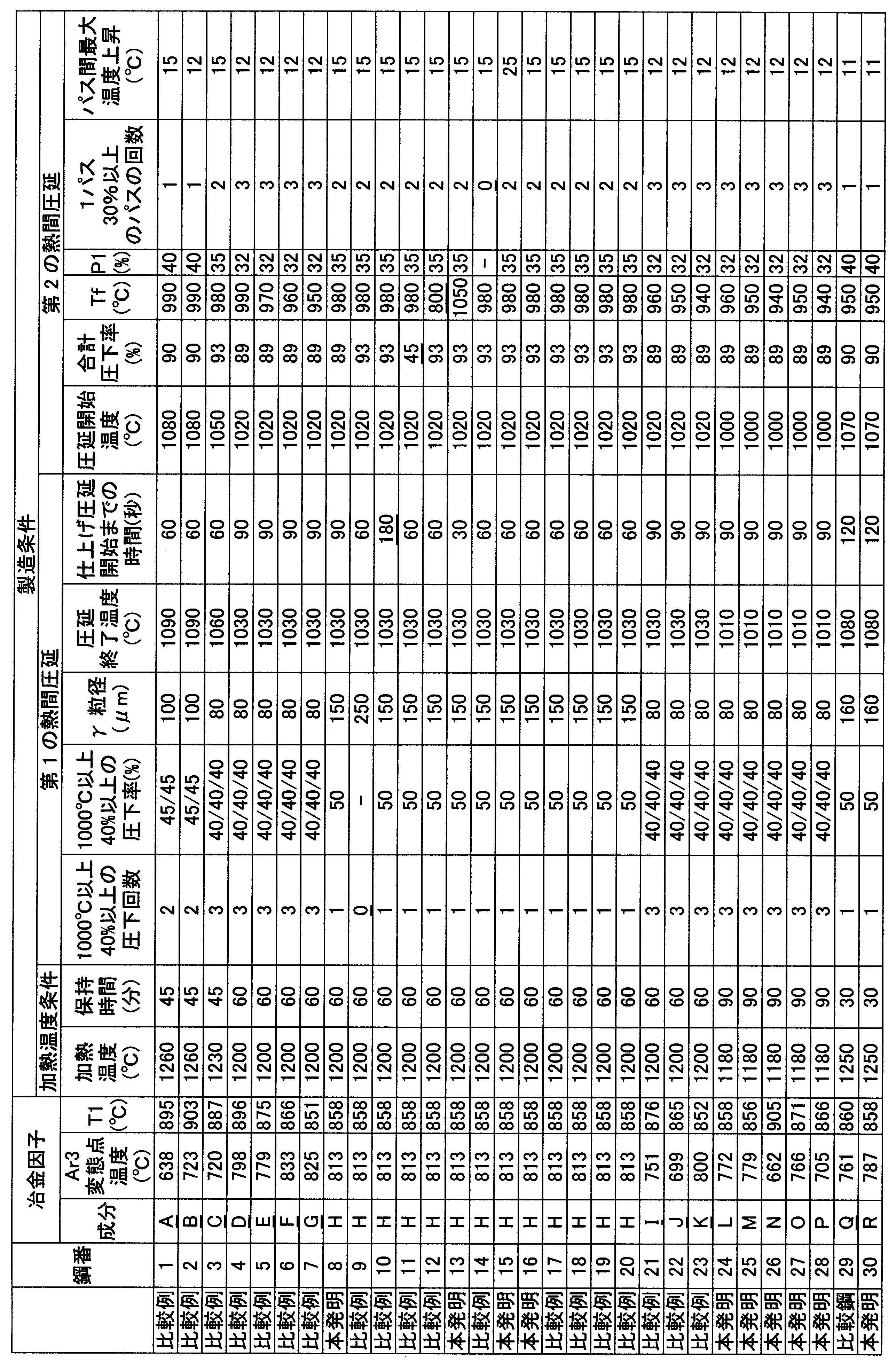
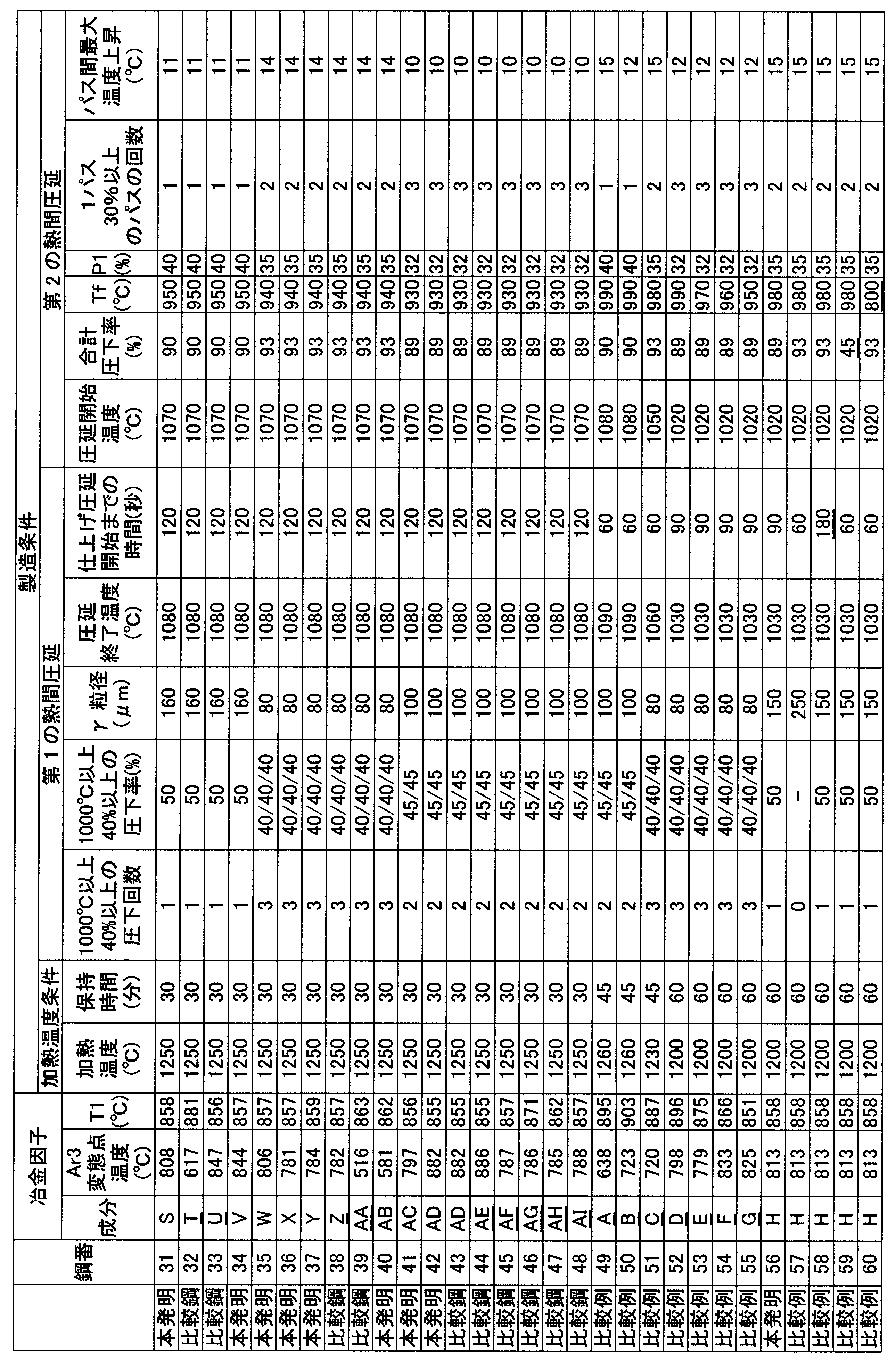
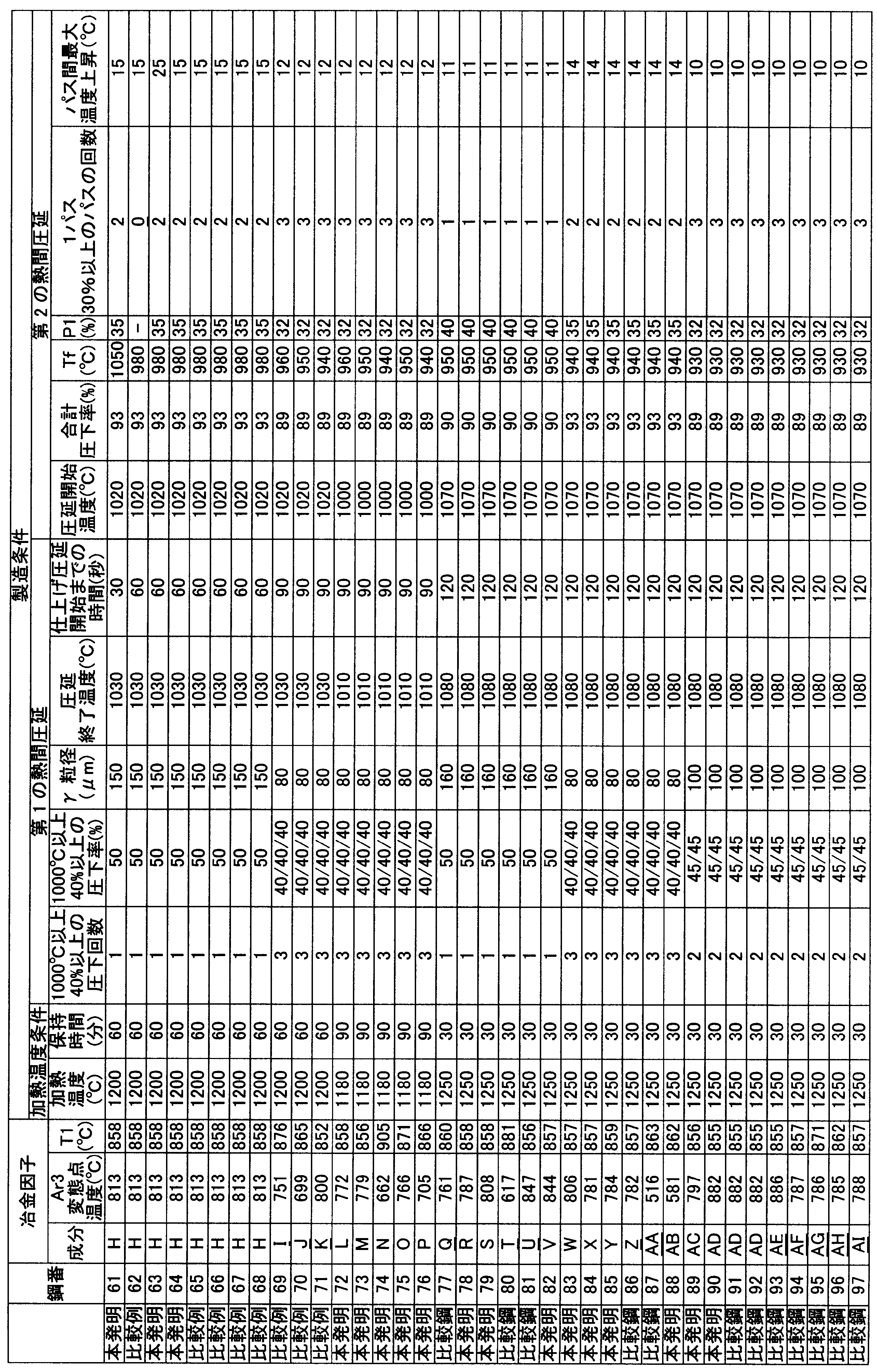
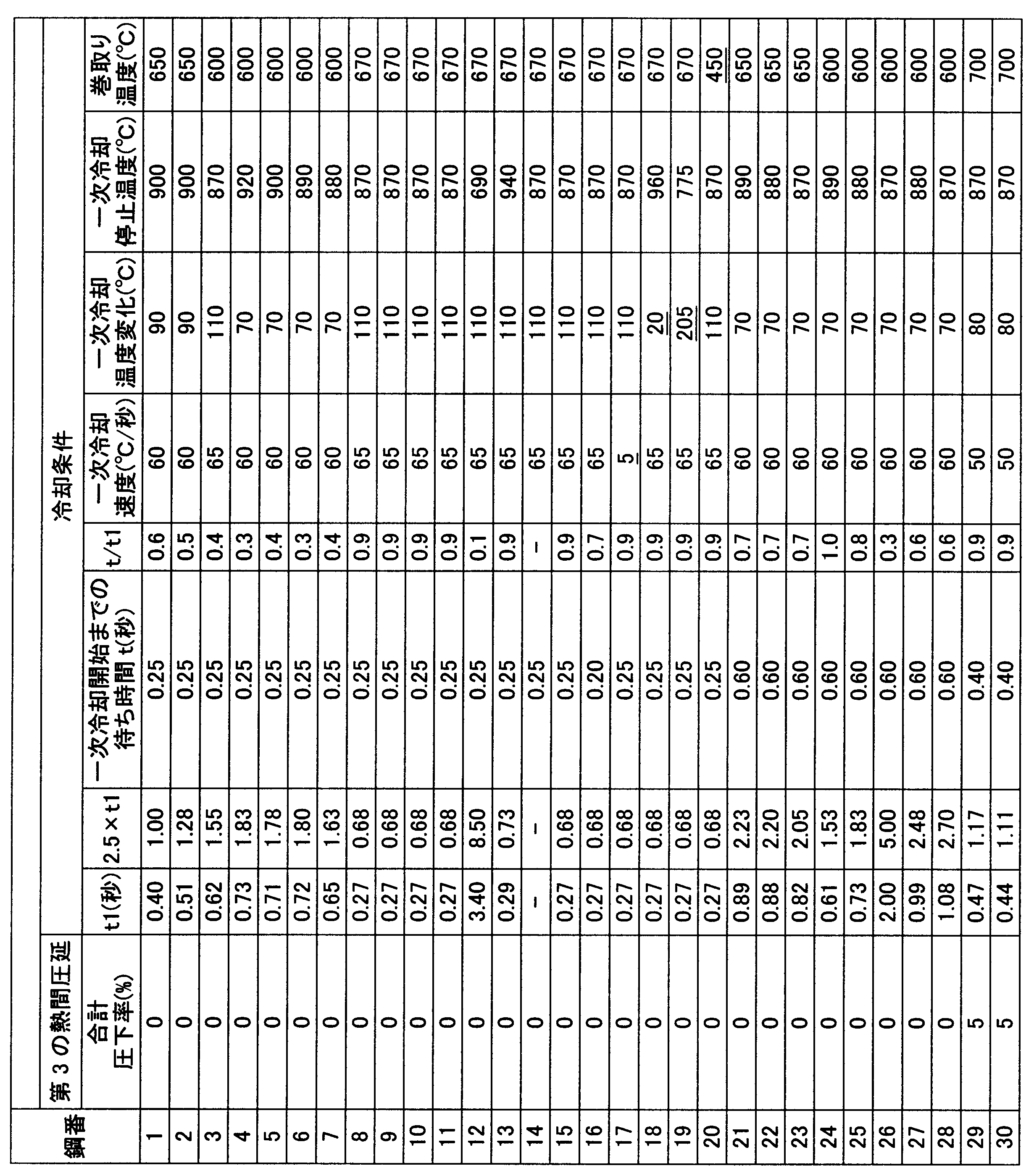


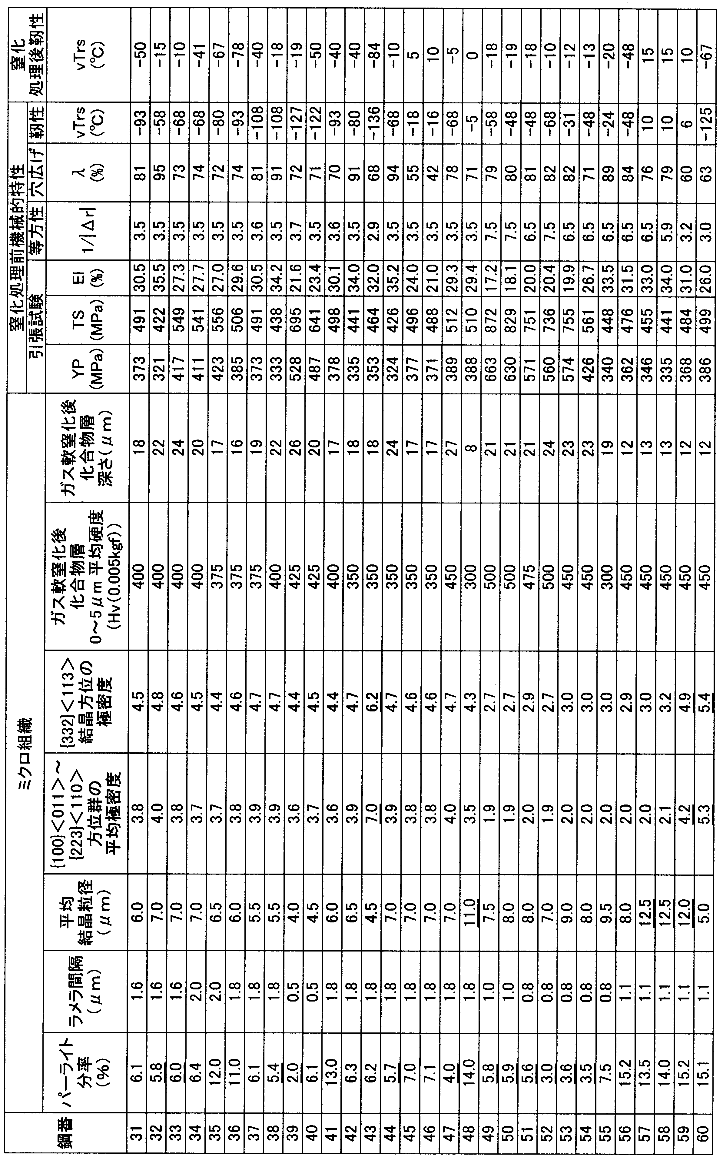
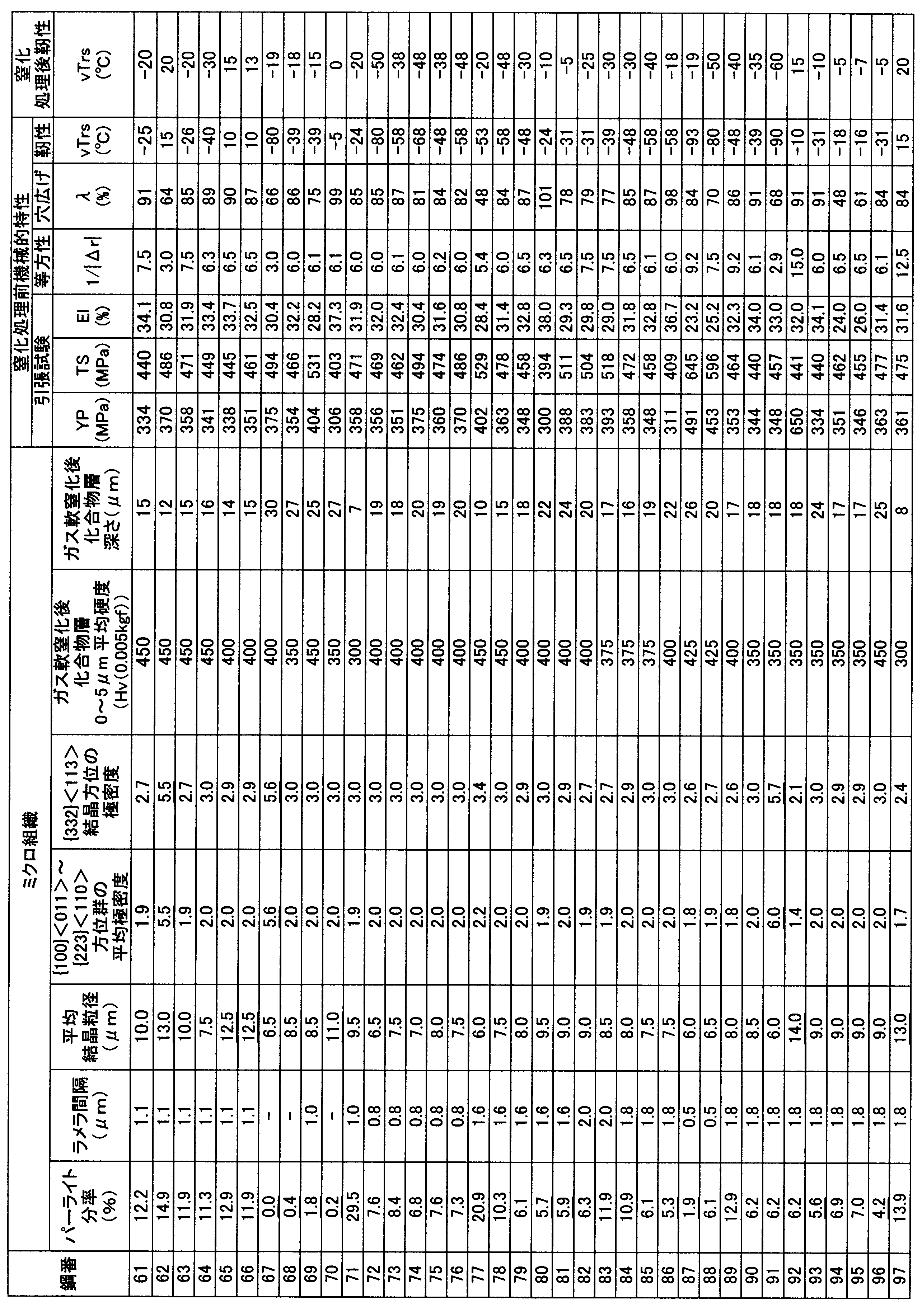
Claims (11)
- 質量%で、
C含有量[C]が0.07%超0.2%以下のCと、
Si含有量[Si]が0.001%以上2.5%以下のSiと、
Mn含有量[Mn]が:0.01%以上4%以下のMnと、
Al含有量[Al]が:0.001%以上2%以下のAlと、
を含有し、
P含有量[P]を0.15%以下、
S含有量[S]を0.03%以下、
N含有量[N]を0.01%以下、
に制限し、
さらに、Ti含有量[Ti]が、以下の式1を満たすTiを含有し、
残部がFe及び不可避的不純物からなり;
鋼板の表面から5/8~3/8の板厚範囲である板厚中央部における{100}<011>、{116}<110>、{114}<110>、{112}<110>、{223}<110>の各方位の極密度の相加平均で表わされる{100}<011>~{223}<110>方位群の平均極密度が1.0以上4.0以下で、かつ{332}<113>の結晶方位の極密度が1.0以上4.8以下であり、
さらに、板厚中心での平均結晶粒径が10μm以下であり;
ミクロ組織が、組織分率で6%超のパーライトと残部がフェライトからなる;
ことを特徴とするガス軟窒化用熱延鋼板。
0.005+[N]×48/14+[S]×48/32≦Ti≦0.015+[N]×48/14+[S]×48/32・・・(1) - 前記{100}<011>~{223}<110>方位群の前記平均極密度が2.0以下で、かつ、前記{332}<113>の結晶方位の前記極密度が3.0以下であることを特徴とする請求項1に記載のガス軟窒化用熱延鋼板。
- 前記平均結晶粒径が7μm以下であることを特徴とする請求項1に記載のガス軟窒化用熱延鋼板。
- さらに、質量%で、
Nb含有量[Nb]が0.005%以上0.06%以下のNbと、
Cu含有量[Cu]が:0.02%以上1.2%以下のCuと、
Ni含有量[Ni]が:0.01%以上0.6%以下のNiと、
Mo含有量[Mo]が:0.01%以上1%以下のMoと、
V含有量[V]が:0.01%以上0.2%以下のVと、
Cr含有量[Cr]が:0.01%以上2%以下のCrと、
Mg含有量[Mg]が:0.0005%以上0.01%以下のMgと、
Ca含有量[Ca]が:0.0005%以上0.01%以下のCaと、
REM含有量[REM]が:0.0005%以上0.1%以下のREMと、
B含有量[B]が:0.0002%以上0.002%以下のBと、
のいずれか一種又は二種以上を含有することを特徴とする請求項1~3のいずれか一項に記載のガス軟窒化用熱延鋼板。 - 質量%で、
C含有量[C]が0.07%超0.2%以下のCと、
Si含有量[Si]が0.001%以上2.5%以下のSiと、
Mn含有量[Mn]が:0.01%以上4%以下のMnと、
Al含有量[Al]が:0.001%以上2%以下のAlと、
を含有し、
P含有量[P]を0.15%以下、
S含有量[S]を0.03%以下、
N含有量[N]を0.01%以下、
に制限し、
さらに、Ti含有量[Ti]が、以下の式1を満たすTiを含有し、
残部がFe及び不可避的不純物からなる鋼塊またはスラブを、
1000℃以上1200℃以下の温度域で圧下率が40%以上の圧下を1回以上行う第1の熱間圧延を行い;
前記第1の熱間圧延完了後から150秒以内に1000℃以上の温度域で第2の熱間圧延を開始し;
前記第2の熱間圧延では、下記式2において鋼板成分により決定される温度をT1℃とした場合に、T1+30℃以上T1+200℃以下の温度範囲において、少なくとも1回は1パス30%以上の圧延を行い、かつ、圧下率の合計が50%以上となる圧下を行い;
Ar3変態点温度以上T1+30℃未満の温度範囲で、圧下率の合計が30%以下である第3の熱間圧延を行い;
Ar3変態点温度以上で熱間圧延を終了し;
T1+30℃以上T1+200℃以下の温度範囲における30%以上の圧下率のパスを大圧下パスとした場合、前記大圧下パスのうちの最終パスの完了から冷却開始までの待ち時間t秒が下式3を満たすように、50℃/秒以上の冷却速度で、冷却温度変化が40℃以上140℃以下でかつ、冷却終了温度がT1+100℃以下となる冷却を行い;
550℃超で巻き取る;
ことを特徴とするガス軟窒化用熱延鋼板の製造方法。
0.005+[N]×48/14+[S]×48/32≦Ti≦0.015+[N]×48/14+[S]×48/32・・・(1)
T1=850+10×([C]+[N])×[Mn]+350×[Nb]+250×[Ti]+40×[B]+10×[Cr]+100×[Mo]+100×[V]・・・(2)
t≦2.5×t1・・・(3)
ここで、t1は下記式4で表される。
t1=0.001×((Tf-T1)×P1/100)2-0.109×((Tf-T1)×P1/100)+3.1・・・(4)
ここで、Tfは、大圧下パスの最終パス圧下後の温度(℃)、P1は、大圧下パスの最終パスの圧下率(%)である。 - 前記一次冷却は、圧延スタンド間において冷却を行うことを特徴とする請求項5に記載のガス軟窒化用熱延鋼板の製造方法。
- 前記待ち時間t秒が、更に、下記式5を満たすことを特徴とする請求項5または6に記載のガス軟窒化用熱延鋼板の製造方法。
t1≦t≦2.5×t1・・・(5) - 前記待ち時間t秒が、さらに、下記式6を満たすことを特徴とする請求項5または6に記載のガス軟窒化用熱延鋼板の製造方法。
t<t1・・・(6) - 前記第2の熱間圧延における各パス間の温度上昇を18℃以下とすることを特徴とする請求項5または6に記載のガス軟窒化用熱延鋼板の製造方法。
- 前記スラブまたは鋼塊が、さらに、質量%で、
Nb含有量[Nb]が0.005%以上0.06%以下のNbと、
Cu含有量[Cu]が:0.02%以上1.2%以下のCuと、
Ni含有量[Ni]が:0.01%以上0.6%以下のNiと、
Mo含有量[Mo]が:0.01%以上1%以下のMoと、
V含有量[V]が:0.01%以上0.2%以下のVと、
Cr含有量[Cr]が:0.01%以上2%以下のCrと、
Mg含有量[Mg]が:0.0005%以上0.01%以下のMgと、
Ca含有量[Ca]が:0.0005%以上0.01%以下のCaと、
REM含有量[REM]が:0.0005%以上0.1%以下のREMと、
B含有量[B]が:0.0002%以上0.002%以下のBと、
のいずれか一種又は二種以上を含有することを特徴とする請求項9に記載のガス軟窒化用熱延鋼板。 - 前記スラブまたは鋼塊が、さらに、質量%で、
Nb含有量[Nb]が0.005%以上0.06%以下のNbと、
Cu含有量[Cu]が:0.02%以上1.2%以下のCuと、
Ni含有量[Ni]が:0.01%以上0.6%以下のNiと、
Mo含有量[Mo]が:0.01%以上1%以下のMoと、
V含有量[V]が:0.01%以上0.2%以下のVと、
Cr含有量[Cr]が:0.01%以上2%以下のCrと、
Mg含有量[Mg]が:0.0005%以上0.01%以下のMgと、
Ca含有量[Ca]が:0.0005%以上0.01%以下のCaと、
REM含有量[REM]が:0.0005%以上0.1%以下のREMと、
B含有量[B]が:0.0002%以上0.002%以下のBと、
のいずれか一種又は二種以上を含有することを特徴とする請求項5または6に記載のガス軟窒化用熱延鋼板。
Priority Applications (11)
| Application Number | Priority Date | Filing Date | Title |
|---|---|---|---|
| EP12771020.0A EP2698443B1 (en) | 2011-04-13 | 2012-04-13 | Hot-rolled steel for gaseous nitrocarburizing and manufacturing method thereof |
| MX2013011812A MX358644B (es) | 2011-04-13 | 2012-04-13 | Acero laminado en caliente para nitrocarburación gaseosa y método de fabricación del mismo. |
| US14/110,551 US9453269B2 (en) | 2011-04-13 | 2012-04-13 | Hot-rolled steel sheet for gas nitrocarburizing and manufacturing method thereof |
| KR1020137027173A KR101540877B1 (ko) | 2011-04-13 | 2012-04-13 | 가스 연질화용 열연 강판 및 그 제조 방법 |
| ES12771020.0T ES2662384T3 (es) | 2011-04-13 | 2012-04-13 | Acero laminado en caliente para nitrocarburación gaseosa y método de fabricación del mismo |
| BR112013026185A BR112013026185A2 (pt) | 2011-04-13 | 2012-04-13 | folha de aço laminada à quente para nitrocarbonetação gasosa e processo para fabricação da mesma |
| JP2013509981A JP5454738B2 (ja) | 2011-04-13 | 2012-04-13 | ガス軟窒化用熱延鋼板及びその製造方法 |
| PL12771020T PL2698443T3 (pl) | 2011-04-13 | 2012-04-13 | Stal walcowana na gorąco do cyjanowania gazowego i sposób jej wytwarzania |
| CN201280017163.XA CN103534379B (zh) | 2011-04-13 | 2012-04-13 | 气体氮碳共渗用热轧钢板及其制造方法 |
| CA2832890A CA2832890C (en) | 2011-04-13 | 2012-04-13 | Hot-rolled steel sheet for gas nitrocarburizing and manufacturing method thereof |
| US15/239,497 US9797024B2 (en) | 2011-04-13 | 2016-08-17 | Hot-rolled steel sheet for gas nitrocarburizing and manufacturing method thereof |
Applications Claiming Priority (2)
| Application Number | Priority Date | Filing Date | Title |
|---|---|---|---|
| JP2011089491 | 2011-04-13 | ||
| JP2011-089491 | 2011-04-13 |
Related Child Applications (2)
| Application Number | Title | Priority Date | Filing Date |
|---|---|---|---|
| US14/110,551 A-371-Of-International US9453269B2 (en) | 2011-04-13 | 2012-04-13 | Hot-rolled steel sheet for gas nitrocarburizing and manufacturing method thereof |
| US15/239,497 Division US9797024B2 (en) | 2011-04-13 | 2016-08-17 | Hot-rolled steel sheet for gas nitrocarburizing and manufacturing method thereof |
Publications (1)
| Publication Number | Publication Date |
|---|---|
| WO2012141297A1 true WO2012141297A1 (ja) | 2012-10-18 |
Family
ID=47009455
Family Applications (1)
| Application Number | Title | Priority Date | Filing Date |
|---|---|---|---|
| PCT/JP2012/060151 Ceased WO2012141297A1 (ja) | 2011-04-13 | 2012-04-13 | ガス軟窒化用熱延鋼板及びその製造方法 |
Country Status (12)
| Country | Link |
|---|---|
| US (2) | US9453269B2 (ja) |
| EP (1) | EP2698443B1 (ja) |
| JP (1) | JP5454738B2 (ja) |
| KR (1) | KR101540877B1 (ja) |
| CN (1) | CN103534379B (ja) |
| BR (1) | BR112013026185A2 (ja) |
| CA (1) | CA2832890C (ja) |
| ES (1) | ES2662384T3 (ja) |
| MX (1) | MX358644B (ja) |
| PL (1) | PL2698443T3 (ja) |
| TW (1) | TWI443201B (ja) |
| WO (1) | WO2012141297A1 (ja) |
Cited By (9)
| Publication number | Priority date | Publication date | Assignee | Title |
|---|---|---|---|---|
| JP2014185359A (ja) * | 2013-03-22 | 2014-10-02 | Jfe Steel Corp | 高強度鋼板 |
| JP2015081367A (ja) * | 2013-10-22 | 2015-04-27 | 株式会社神戸製鋼所 | 絞り加工性と浸炭熱処理後の表面硬さに優れる熱延鋼板 |
| WO2015190618A1 (ja) * | 2014-06-13 | 2015-12-17 | 新日鐵住金株式会社 | 軟窒化処理用鋼板およびその製造方法と軟窒化処理鋼 |
| US9850553B2 (en) * | 2014-07-22 | 2017-12-26 | Roll Forming Corporation | System and method for producing a hardened and tempered structural member |
| JP2018051596A (ja) * | 2016-09-29 | 2018-04-05 | Jfeスチール株式会社 | 鋼板の製造方法および製造設備 |
| KR20210091790A (ko) | 2019-03-29 | 2021-07-22 | 닛폰세이테츠 가부시키가이샤 | 강판 |
| WO2022176984A1 (ja) * | 2021-02-18 | 2022-08-25 | 日本製鉄株式会社 | ガス軟窒化用鋼板 |
| CN115917030A (zh) * | 2020-09-30 | 2023-04-04 | 日本制铁株式会社 | 高强度钢板 |
| JP2024025848A (ja) * | 2022-08-15 | 2024-02-28 | 日本製鉄株式会社 | 鋼歯車及び鋼歯車の製造方法 |
Families Citing this family (17)
| Publication number | Priority date | Publication date | Assignee | Title |
|---|---|---|---|---|
| JP5630523B2 (ja) * | 2013-04-02 | 2014-11-26 | Jfeスチール株式会社 | 窒化処理用鋼板およびその製造方法 |
| US11401571B2 (en) * | 2015-02-20 | 2022-08-02 | Nippon Steel Corporation | Hot-rolled steel sheet |
| WO2016132549A1 (ja) | 2015-02-20 | 2016-08-25 | 新日鐵住金株式会社 | 熱延鋼板 |
| WO2016135898A1 (ja) | 2015-02-25 | 2016-09-01 | 新日鐵住金株式会社 | 熱延鋼板 |
| JP6399201B2 (ja) | 2015-02-25 | 2018-10-03 | 新日鐵住金株式会社 | 熱延鋼板 |
| KR101664098B1 (ko) * | 2015-09-01 | 2016-10-10 | 주식회사 포스코 | 압력용기용 열연강판 및 그 제조방법 |
| WO2017168436A1 (en) * | 2016-03-30 | 2017-10-05 | Tata Steel Limited | A HOT ROLLED HIGH STRENGTH STEEL (HRHSS) PRODUCT WITH TENSILE STRENGTH OF 1000 -1200 MPa AND TOTAL ELONGATION OF 16%-17% |
| US10889879B2 (en) | 2016-08-05 | 2021-01-12 | Nippon Steel Corporation | Steel sheet and plated steel sheet |
| KR102186320B1 (ko) | 2016-08-05 | 2020-12-03 | 닛폰세이테츠 가부시키가이샤 | 강판 및 도금 강판 |
| BR112019000306B1 (pt) * | 2016-08-05 | 2023-02-14 | Nippon Steel Corporation | Chapa de aço e chapa de aço galvanizada |
| US10633726B2 (en) * | 2017-08-16 | 2020-04-28 | The United States Of America As Represented By The Secretary Of The Army | Methods, compositions and structures for advanced design low alloy nitrogen steels |
| US10870910B2 (en) * | 2018-01-10 | 2020-12-22 | GM Global Technology Operations LLC | Ferritic nitrocarburized part and methods of making and using the same |
| KR102484995B1 (ko) * | 2020-12-10 | 2023-01-04 | 주식회사 포스코 | 진공열차 튜브용 열연강판 및 그 제조방법 |
| KR102484994B1 (ko) * | 2020-12-10 | 2023-01-04 | 주식회사 포스코 | 진공열차 튜브용 열연강판 및 그 제조방법 |
| KR102900041B1 (ko) * | 2021-05-13 | 2025-12-15 | 닛폰세이테츠 가부시키가이샤 | 핫 스탬프용 강판 및 핫 스탬프 성형체 |
| CN114166605B (zh) * | 2021-12-07 | 2024-03-29 | 安徽林洪重工科技有限公司 | 一种模拟与预测大尺寸CrMo钢构件心部组织性能的方法 |
| CN115090676A (zh) * | 2022-06-27 | 2022-09-23 | 南京钢铁股份有限公司 | 一种钢领用优碳钢热轧窄带钢的制备方法 |
Citations (8)
| Publication number | Priority date | Publication date | Assignee | Title |
|---|---|---|---|---|
| JPH06293910A (ja) | 1993-04-07 | 1994-10-21 | Nippon Steel Corp | 穴拡げ性と延性に優れた高強度熱延鋼板の製造方法 |
| JPH0949065A (ja) * | 1995-08-07 | 1997-02-18 | Kobe Steel Ltd | 伸びフランジ性にすぐれる耐摩耗用熱延鋼板及びその製造方法 |
| JPH10183255A (ja) | 1996-12-20 | 1998-07-14 | Nippon Steel Corp | r値の面内異方性の小さい熱延鋼板の製造方法 |
| JP2002322541A (ja) | 2000-10-31 | 2002-11-08 | Nkk Corp | 材質均一性に優れた高成形性高張力熱延鋼板ならびにその製造方法および加工方法 |
| JP2002322540A (ja) | 2000-10-31 | 2002-11-08 | Nkk Corp | 伸びおよび伸びフランジ性に優れた高張力熱延鋼板ならびにその製造方法および加工方法 |
| JP2006124789A (ja) | 2004-10-29 | 2006-05-18 | Jfe Steel Kk | 加工性に優れた高強度熱延鋼板およびその製造方法 |
| JP2009068057A (ja) * | 2007-09-12 | 2009-04-02 | Jfe Steel Kk | 軟窒化処理用鋼板およびその製造方法 |
| WO2012014926A1 (ja) * | 2010-07-28 | 2012-02-02 | 新日本製鐵株式会社 | 熱延鋼板、冷延鋼板、亜鉛めっき鋼板およびこれらの製造方法 |
Family Cites Families (25)
| Publication number | Priority date | Publication date | Assignee | Title |
|---|---|---|---|---|
| JPS62192539A (ja) | 1986-02-18 | 1987-08-24 | Nippon Steel Corp | 高f値熱延鋼板の製造方法 |
| JP3039862B1 (ja) * | 1998-11-10 | 2000-05-08 | 川崎製鉄株式会社 | 超微細粒を有する加工用熱延鋼板 |
| JP3858551B2 (ja) | 1999-02-09 | 2006-12-13 | Jfeスチール株式会社 | 焼付硬化性、耐疲労性、耐衝撃性および耐常温時効性に優れた高張力熱延鋼板およびその製造方法 |
| JP3927384B2 (ja) | 2001-02-23 | 2007-06-06 | 新日本製鐵株式会社 | 切り欠き疲労強度に優れる自動車用薄鋼板およびその製造方法 |
| DE60224557T4 (de) * | 2001-10-04 | 2015-06-25 | Nippon Steel & Sumitomo Metal Corporation | Ziehbares hochfestes dünnes Stahlblech mit hervorragender Formfixierungseigenschaft und Herstellungsverfahren dafür |
| JP3848211B2 (ja) * | 2002-05-31 | 2006-11-22 | 株式会社神戸製鋼所 | 低温靭性に優れた厚鋼板およびその製造方法 |
| JP4189194B2 (ja) * | 2002-10-08 | 2008-12-03 | 新日本製鐵株式会社 | 加工性と形状凍結性に優れた冷延鋼板及びその製造方法 |
| TWI248977B (en) | 2003-06-26 | 2006-02-11 | Nippon Steel Corp | High-strength hot-rolled steel sheet excellent in shape fixability and method of producing the same |
| CN100526493C (zh) | 2004-07-27 | 2009-08-12 | 新日本制铁株式会社 | 高杨氏模量钢板、使用了它的热浸镀锌钢板、合金化热浸镀锌钢板、和高杨氏模量钢管以及它们的制造方法 |
| JP4555693B2 (ja) | 2005-01-17 | 2010-10-06 | 新日本製鐵株式会社 | 深絞り性に優れた高強度冷延鋼板およびその製造方法 |
| JP5228447B2 (ja) | 2006-11-07 | 2013-07-03 | 新日鐵住金株式会社 | 高ヤング率鋼板及びその製造方法 |
| JP5092433B2 (ja) | 2007-02-02 | 2012-12-05 | 住友金属工業株式会社 | 熱延鋼板及びその製造方法 |
| JP5223375B2 (ja) | 2007-03-01 | 2013-06-26 | 新日鐵住金株式会社 | 低温靭性に優れるラインパイプ用高強度熱延鋼板およびその製造方法 |
| JP5214905B2 (ja) | 2007-04-17 | 2013-06-19 | 株式会社中山製鋼所 | 高強度熱延鋼板およびその製造方法 |
| JP5037413B2 (ja) | 2007-04-19 | 2012-09-26 | 新日本製鐵株式会社 | 低降伏比高ヤング率鋼板、溶融亜鉛メッキ鋼板、合金化溶融亜鉛メッキ鋼板、及び、鋼管、並びに、それらの製造方法 |
| JP4905240B2 (ja) | 2007-04-27 | 2012-03-28 | Jfeスチール株式会社 | 表面品質、破壊靱性および耐サワー性に優れる熱延鋼板の製造方法 |
| JP5068689B2 (ja) | 2008-04-24 | 2012-11-07 | 新日本製鐵株式会社 | 穴広げ性に優れた熱延鋼板 |
| JP5068688B2 (ja) | 2008-04-24 | 2012-11-07 | 新日本製鐵株式会社 | 穴広げ性に優れた熱延鋼板 |
| JP5394709B2 (ja) | 2008-11-28 | 2014-01-22 | 株式会社神戸製鋼所 | 耐水素脆化特性および加工性に優れた超高強度鋼板 |
| JP4998755B2 (ja) | 2009-05-12 | 2012-08-15 | Jfeスチール株式会社 | 高強度熱延鋼板およびその製造方法 |
| JP5338525B2 (ja) * | 2009-07-02 | 2013-11-13 | 新日鐵住金株式会社 | バーリング性に優れた高降伏比型熱延鋼板及びその製造方法 |
| JP5453964B2 (ja) | 2009-07-08 | 2014-03-26 | Jfeスチール株式会社 | 高強度熱延鋼板およびその製造方法 |
| JP5278226B2 (ja) | 2009-07-29 | 2013-09-04 | 新日鐵住金株式会社 | 省合金型高強度熱延鋼板及びその製造方法 |
| JP5560336B2 (ja) | 2010-07-28 | 2014-07-23 | Ykk株式会社 | 固定具、シート、及びカバー固定方法 |
| JP5126326B2 (ja) | 2010-09-17 | 2013-01-23 | Jfeスチール株式会社 | 耐疲労特性に優れた高強度熱延鋼板およびその製造方法 |
-
2012
- 2012-04-13 PL PL12771020T patent/PL2698443T3/pl unknown
- 2012-04-13 JP JP2013509981A patent/JP5454738B2/ja active Active
- 2012-04-13 CN CN201280017163.XA patent/CN103534379B/zh not_active Expired - Fee Related
- 2012-04-13 TW TW101113229A patent/TWI443201B/zh not_active IP Right Cessation
- 2012-04-13 KR KR1020137027173A patent/KR101540877B1/ko not_active Expired - Fee Related
- 2012-04-13 US US14/110,551 patent/US9453269B2/en not_active Expired - Fee Related
- 2012-04-13 CA CA2832890A patent/CA2832890C/en not_active Expired - Fee Related
- 2012-04-13 MX MX2013011812A patent/MX358644B/es active IP Right Grant
- 2012-04-13 BR BR112013026185A patent/BR112013026185A2/pt not_active IP Right Cessation
- 2012-04-13 EP EP12771020.0A patent/EP2698443B1/en not_active Not-in-force
- 2012-04-13 WO PCT/JP2012/060151 patent/WO2012141297A1/ja not_active Ceased
- 2012-04-13 ES ES12771020.0T patent/ES2662384T3/es active Active
-
2016
- 2016-08-17 US US15/239,497 patent/US9797024B2/en not_active Expired - Fee Related
Patent Citations (8)
| Publication number | Priority date | Publication date | Assignee | Title |
|---|---|---|---|---|
| JPH06293910A (ja) | 1993-04-07 | 1994-10-21 | Nippon Steel Corp | 穴拡げ性と延性に優れた高強度熱延鋼板の製造方法 |
| JPH0949065A (ja) * | 1995-08-07 | 1997-02-18 | Kobe Steel Ltd | 伸びフランジ性にすぐれる耐摩耗用熱延鋼板及びその製造方法 |
| JPH10183255A (ja) | 1996-12-20 | 1998-07-14 | Nippon Steel Corp | r値の面内異方性の小さい熱延鋼板の製造方法 |
| JP2002322541A (ja) | 2000-10-31 | 2002-11-08 | Nkk Corp | 材質均一性に優れた高成形性高張力熱延鋼板ならびにその製造方法および加工方法 |
| JP2002322540A (ja) | 2000-10-31 | 2002-11-08 | Nkk Corp | 伸びおよび伸びフランジ性に優れた高張力熱延鋼板ならびにその製造方法および加工方法 |
| JP2006124789A (ja) | 2004-10-29 | 2006-05-18 | Jfe Steel Kk | 加工性に優れた高強度熱延鋼板およびその製造方法 |
| JP2009068057A (ja) * | 2007-09-12 | 2009-04-02 | Jfe Steel Kk | 軟窒化処理用鋼板およびその製造方法 |
| WO2012014926A1 (ja) * | 2010-07-28 | 2012-02-02 | 新日本製鐵株式会社 | 熱延鋼板、冷延鋼板、亜鉛めっき鋼板およびこれらの製造方法 |
Cited By (20)
| Publication number | Priority date | Publication date | Assignee | Title |
|---|---|---|---|---|
| JP2014185359A (ja) * | 2013-03-22 | 2014-10-02 | Jfe Steel Corp | 高強度鋼板 |
| JP2015081367A (ja) * | 2013-10-22 | 2015-04-27 | 株式会社神戸製鋼所 | 絞り加工性と浸炭熱処理後の表面硬さに優れる熱延鋼板 |
| WO2015060311A1 (ja) * | 2013-10-22 | 2015-04-30 | 株式会社神戸製鋼所 | 絞り加工性と浸炭熱処理後の表面硬さに優れる熱延鋼板 |
| CN105658830A (zh) * | 2013-10-22 | 2016-06-08 | 株式会社神户制钢所 | 拉伸加工性和渗碳热处理后的表面硬度优异的热轧钢板 |
| WO2015190618A1 (ja) * | 2014-06-13 | 2015-12-17 | 新日鐵住金株式会社 | 軟窒化処理用鋼板およびその製造方法と軟窒化処理鋼 |
| JPWO2015190618A1 (ja) * | 2014-06-13 | 2017-04-20 | 新日鐵住金株式会社 | 軟窒化処理用鋼板およびその製造方法と軟窒化処理鋼 |
| US10344371B2 (en) | 2014-06-13 | 2019-07-09 | Nippon Steel & Sumitomo Metal Corporation | Steel sheet for soft-nitriding treatment, method of manufacturing same, and soft-nitrided steel |
| US9850553B2 (en) * | 2014-07-22 | 2017-12-26 | Roll Forming Corporation | System and method for producing a hardened and tempered structural member |
| US10697034B2 (en) | 2014-07-22 | 2020-06-30 | Roll Forming Corporation | System and method for producing a hardened and tempered structural member |
| JP2018051596A (ja) * | 2016-09-29 | 2018-04-05 | Jfeスチール株式会社 | 鋼板の製造方法および製造設備 |
| KR20210091790A (ko) | 2019-03-29 | 2021-07-22 | 닛폰세이테츠 가부시키가이샤 | 강판 |
| US11970752B2 (en) | 2019-03-29 | 2024-04-30 | Nippon Steel Corporation | Steel sheet |
| CN115917030A (zh) * | 2020-09-30 | 2023-04-04 | 日本制铁株式会社 | 高强度钢板 |
| CN115917030B (zh) * | 2020-09-30 | 2024-05-31 | 日本制铁株式会社 | 高强度钢板 |
| WO2022176984A1 (ja) * | 2021-02-18 | 2022-08-25 | 日本製鉄株式会社 | ガス軟窒化用鋼板 |
| JPWO2022176984A1 (ja) * | 2021-02-18 | 2022-08-25 | ||
| CN116670304A (zh) * | 2021-02-18 | 2023-08-29 | 日本制铁株式会社 | 气体软氮化用钢板 |
| JP7633558B2 (ja) | 2021-02-18 | 2025-02-20 | 日本製鉄株式会社 | ガス軟窒化用鋼板 |
| JP2024025848A (ja) * | 2022-08-15 | 2024-02-28 | 日本製鉄株式会社 | 鋼歯車及び鋼歯車の製造方法 |
| JP7839405B2 (ja) | 2022-08-15 | 2026-04-02 | 日本製鉄株式会社 | 鋼歯車及び鋼歯車の製造方法 |
Also Published As
| Publication number | Publication date |
|---|---|
| MX358644B (es) | 2018-08-30 |
| US20160355899A1 (en) | 2016-12-08 |
| US20140027022A1 (en) | 2014-01-30 |
| MX2013011812A (es) | 2013-10-25 |
| PL2698443T3 (pl) | 2018-05-30 |
| TW201247892A (en) | 2012-12-01 |
| KR20130135352A (ko) | 2013-12-10 |
| CA2832890C (en) | 2016-03-29 |
| US9797024B2 (en) | 2017-10-24 |
| JP5454738B2 (ja) | 2014-03-26 |
| CA2832890A1 (en) | 2012-10-18 |
| ES2662384T3 (es) | 2018-04-06 |
| US9453269B2 (en) | 2016-09-27 |
| TWI443201B (zh) | 2014-07-01 |
| BR112013026185A2 (pt) | 2016-12-20 |
| EP2698443B1 (en) | 2018-01-10 |
| KR101540877B1 (ko) | 2015-07-30 |
| EP2698443A1 (en) | 2014-02-19 |
| EP2698443A4 (en) | 2015-03-11 |
| JPWO2012141297A1 (ja) | 2014-07-28 |
| CN103534379B (zh) | 2016-01-20 |
| CN103534379A (zh) | 2014-01-22 |
Similar Documents
| Publication | Publication Date | Title |
|---|---|---|
| JP5454738B2 (ja) | ガス軟窒化用熱延鋼板及びその製造方法 | |
| US10364478B2 (en) | Bainite-containing-type high-strength hot-rolled steel sheet having excellent isotropic workability and manufacturing method thereof | |
| CN103459648B (zh) | 热轧钢板及其制造方法 | |
| JP5408387B2 (ja) | 局部変形能に優れた高強度熱延鋼板とその製造方法 | |
| CN103459647B (zh) | 热轧钢板及其制造方法 | |
| JP5326709B2 (ja) | 低降伏比型高バーリング性高強度熱延鋼板及びその製造方法 | |
| JP6354274B2 (ja) | 熱延鋼板およびその製造方法 |
Legal Events
| Date | Code | Title | Description |
|---|---|---|---|
| 121 | Ep: the epo has been informed by wipo that ep was designated in this application |
Ref document number: 12771020 Country of ref document: EP Kind code of ref document: A1 |
|
| ENP | Entry into the national phase |
Ref document number: 2013509981 Country of ref document: JP Kind code of ref document: A |
|
| WWE | Wipo information: entry into national phase |
Ref document number: 14110551 Country of ref document: US |
|
| ENP | Entry into the national phase |
Ref document number: 2832890 Country of ref document: CA |
|
| WWE | Wipo information: entry into national phase |
Ref document number: MX/A/2013/011812 Country of ref document: MX |
|
| NENP | Non-entry into the national phase |
Ref country code: DE |
|
| ENP | Entry into the national phase |
Ref document number: 20137027173 Country of ref document: KR Kind code of ref document: A |
|
| WWE | Wipo information: entry into national phase |
Ref document number: 2012771020 Country of ref document: EP |
|
| REG | Reference to national code |
Ref country code: BR Ref legal event code: B01A Ref document number: 112013026185 Country of ref document: BR |
|
| ENP | Entry into the national phase |
Ref document number: 112013026185 Country of ref document: BR Kind code of ref document: A2 Effective date: 20131010 |