WO2012140690A1 - ターボファン、および空気調和機 - Google Patents
ターボファン、および空気調和機 Download PDFInfo
- Publication number
- WO2012140690A1 WO2012140690A1 PCT/JP2011/002141 JP2011002141W WO2012140690A1 WO 2012140690 A1 WO2012140690 A1 WO 2012140690A1 JP 2011002141 W JP2011002141 W JP 2011002141W WO 2012140690 A1 WO2012140690 A1 WO 2012140690A1
- Authority
- WO
- WIPO (PCT)
- Prior art keywords
- blade
- trailing edge
- wing
- leading edge
- main plate
- Prior art date
Links
Images


Classifications
-
- F—MECHANICAL ENGINEERING; LIGHTING; HEATING; WEAPONS; BLASTING
- F01—MACHINES OR ENGINES IN GENERAL; ENGINE PLANTS IN GENERAL; STEAM ENGINES
- F01D—NON-POSITIVE DISPLACEMENT MACHINES OR ENGINES, e.g. STEAM TURBINES
- F01D5/00—Blades; Blade-carrying members; Heating, heat-insulating, cooling or antivibration means on the blades or the members
-
- F—MECHANICAL ENGINEERING; LIGHTING; HEATING; WEAPONS; BLASTING
- F04—POSITIVE - DISPLACEMENT MACHINES FOR LIQUIDS; PUMPS FOR LIQUIDS OR ELASTIC FLUIDS
- F04D—NON-POSITIVE-DISPLACEMENT PUMPS
- F04D29/00—Details, component parts, or accessories
- F04D29/26—Rotors specially for elastic fluids
- F04D29/28—Rotors specially for elastic fluids for centrifugal or helico-centrifugal pumps for radial-flow or helico-centrifugal pumps
- F04D29/281—Rotors specially for elastic fluids for centrifugal or helico-centrifugal pumps for radial-flow or helico-centrifugal pumps for fans or blowers
-
- F—MECHANICAL ENGINEERING; LIGHTING; HEATING; WEAPONS; BLASTING
- F04—POSITIVE - DISPLACEMENT MACHINES FOR LIQUIDS; PUMPS FOR LIQUIDS OR ELASTIC FLUIDS
- F04D—NON-POSITIVE-DISPLACEMENT PUMPS
- F04D29/00—Details, component parts, or accessories
- F04D29/26—Rotors specially for elastic fluids
- F04D29/28—Rotors specially for elastic fluids for centrifugal or helico-centrifugal pumps for radial-flow or helico-centrifugal pumps
- F04D29/30—Vanes
-
- F—MECHANICAL ENGINEERING; LIGHTING; HEATING; WEAPONS; BLASTING
- F04—POSITIVE - DISPLACEMENT MACHINES FOR LIQUIDS; PUMPS FOR LIQUIDS OR ELASTIC FLUIDS
- F04D—NON-POSITIVE-DISPLACEMENT PUMPS
- F04D29/00—Details, component parts, or accessories
- F04D29/66—Combating cavitation, whirls, noise, vibration or the like; Balancing
- F04D29/68—Combating cavitation, whirls, noise, vibration or the like; Balancing by influencing boundary layers
- F04D29/681—Combating cavitation, whirls, noise, vibration or the like; Balancing by influencing boundary layers especially adapted for elastic fluid pumps
Definitions
- the present invention relates to a turbo fan and an air conditioner including the turbo fan.
- a plurality of blade plates, a main plate to which the blade plates are fixed, and a side plate fixed to the end surface on the side opposite to the main plate of the blade plate constitute an impeller, and the suction surface of the blade plate
- An impeller of a centrifugal blower that constitutes a blade shape holding mechanism for preventing the second surface portion from being deformed toward the outer peripheral side by centrifugal force by abutting the end surface on the first surface portion side of the 42) "has been proposed (see, for example, Patent Document 2).
- Patent Document 1 The technique described in Patent Document 1 is provided with concave portions arranged substantially parallel to the rotation axis on the entire surface or part of the blade suction surface side, and gradually increases the width and depth of the concave portions from the main plate toward the side plate. It is enlarged and formed. As a result, when the airflow that flows near the surface of the blade suction surface tries to separate from the surface of the blade, the amount of air inside the recess provided on the surface of the blade decreases, and the airflow that is about to cause separation due to the negative pressure inside the recess Is pulled back to suppress the occurrence of peeling.
- the recess is substantially parallel to the rotation axis, the recess is substantially orthogonal to the blade leading edge on the side of the blade leading edge facing the fan inlet (side plate side). For this reason, on the side facing the fan suction port (side plate side), there is a problem that the effect of pulling back the airflow in the recess cannot be obtained. As a result, there is a problem that the airflow is separated from the surface of the blade and the noise due to turbulence increases.
- the cross section of the concave portion has a substantially hemispherical shape, when the flow is reattached downstream of the concave portion, the flow collides with the downstream corner portion of the concave portion and peels off, resulting in a pressure fluctuation and increasing noise. There was a problem.
- the present invention has been made to solve the above-described problems, and provides a turbofan and an air conditioner that can suppress separation of airflow on the surface of a blade and reduce noise due to turbulence. is there.
- a turbofan according to the present invention includes a circular main plate that is rotationally driven, an annular side plate that is disposed to face the main plate, and both ends that are joined to the main plate and the side plate, respectively, and the circumferential direction of the main plate
- a plurality of blades arranged at intervals, and the blades are located on the outer peripheral side of the main plate and on the rotation center side of the main plate with respect to the blade rear edge.
- a blade leading edge, and a range close to the main plate of the blade leading edge forms a blade inner circumferential front edge substantially perpendicular to the main plate and is close to the side plate of the blade leading edge
- the range is such that, as the distance from the main plate increases, the blade side plate-side front edge that is inclined so as to approach the blade trailing edge, the pressure surface that is the front surface with respect to the rotation direction of the blade, and the rotation of the blade In the vicinity of the blade leading edge, at least one of the suction surfaces as the rear surface with respect to the direction, the blade inner peripheral side Extending substantially along the edge and the wing side plate side front edge, and recessed in the thickness direction of the wing, and gradually increase the thickness of the wing from the dent to the wing trailing edge
- a blade leading edge side step portion having a thickened inclined portion is formed.
- the present invention can suppress the separation of the airflow on the surface of the wing and can reduce the noise caused by the turbulent flow.
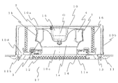
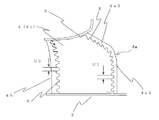
- FIG. 1 is a longitudinal sectional view of an air conditioner showing Embodiment 1.
- FIG. 2 is a suction side view of one blade of the turbofan of FIG. 1.
- FIG. 2 is a pressure side view of one blade of the turbofan of FIG. 1.
- FIG. 5 is a blade horizontal cross-sectional view orthogonal to the fan rotation axis at XX in FIGS. 3 and 4.
- FIG. 5 is a blade cross-sectional view substantially perpendicular to the fan suction port side front edge portion at YY in FIGS. 3 and 4.
- FIG. 4 is a view corresponding to FIG. 3 of a turbofan mounted on an air conditioner showing Embodiment 2.
- FIG. 6 is a view corresponding to FIG.
- FIG. 6 is a view corresponding to FIG. 5 of a turbo fan mounted on an air conditioner showing Embodiment 2.
- FIG. 7 is a view corresponding to FIG. 6 of a turbo fan mounted on an air conditioner showing Embodiment 2.
- FIG. 6 is a view corresponding to FIG. 3 of a turbo fan mounted on an air conditioner showing Embodiment 3.
- FIG. 6 is a view corresponding to FIG. 4 of a turbo fan mounted on an air conditioner showing Embodiment 3.
- FIG. 6 is a view corresponding to FIG. 5 of a turbofan mounted on an air conditioner showing another example of the third embodiment. It is a figure equivalent to FIG. 6 of the turbo fan mounted in the air conditioner which shows Embodiment 3 in another example.
- FIG. 1 is a longitudinal sectional view of an air conditioner showing Embodiment 1.
- FIG. 1 a ceiling-embedded air conditioner will be described as an example, but the present invention is not limited to this.
- the present invention can be widely applied to an air conditioner equipped with a turbo fan having a pressure loss body such as a filter or a heat exchanger on the fan suction side and the blowout side.
- the air conditioner main body 10 is installed in a direction in which the top is a top plate 10 a with respect to a room 17.
- a side plate 10 b is attached around the top plate 10 a and is installed so as to open toward the room 17.
- a substantially rectangular decorative panel 11 in a plan view is attached and faces the room 17.
- a suction grill 11a serving as a suction port for air into the air conditioner body 10
- a filter 12 for removing dust after passing through the suction grill 11a.
- a panel outlet 11 b serving as an air outlet is formed on each side of the decorative panel 11 along each side of the decorative panel 11.
- Each panel outlet 11b is provided with a wind vane 13.
- a turbo fan 1 Inside the air conditioner main body 10, a turbo fan 1, a bell mouth 14 that forms a suction air passage of the turbo fan 1, a fan motor 15 that rotationally drives the turbo fan 1, and a downstream side of the turbo fan 1. And a heat exchanger 16 erected so as to surround it.
- the heat exchanger 16 is connected to an outdoor unit (not shown) through a connection pipe, and the refrigerant is circulated.
- the air conditioner main body 10 has a main body suction port 10c at the center of the lower surface, and a main body outlet 10d around the main body suction port 10c. And the suction grill 11a, the main body inlet 10c, the main body outlet 10d, and the panel outlet 11b are connected.
- the “main body suction port 10c” corresponds to the “suction port” in the present invention. Further, the “panel outlet 11b” corresponds to the “air outlet” in the present invention.
- the “top plate 10a” and the “side plate 10b” correspond to the “housing” in the present invention.
- the air in the room 17 is sucked from the suction grille 11a of the decorative panel 11, passes through the filter 12, and is removed.
- the dust-removed air passes through the main body inlet 10c and the bell mouth 14, and is then sucked into the fan inlet 1a of the turbofan 1.
- Air sucked into the turbo fan 1 is blown out from the fan outlet 1 b of the turbo fan 1 toward the heat exchanger 16.
- the air blown toward the heat exchanger 16 exchanges heat with the refrigerant in the heat exchanger 16 to become air that has been heated, cooled, or dehumidified.
- the air that has been heated, cooled, or dehumidified by the heat exchanger 16 passes through the main body outlet 10d and is blown out from the panel outlet 11b toward the room 17 for air conditioning. At this time, the wind direction is controlled by the wind direction vane 13.
- FIG. 2 is a perspective view of the turbo fan of FIG. 3 is a side view of the suction surface of one blade of the turbo fan of FIG. 4 is a side view of the pressure surface of one blade of the turbo fan of FIG. 2 to 4, the upper side in the figure is the room 17 side for easy understanding. That is, air is sucked from the upper side in the figure toward the lower side in the figure.
- FIG. 2 for easy understanding, a state in which the side plate 3 is partly removed is illustrated.
- symbol is attached
- the turbofan 1 includes a circular main plate 2 that is rotationally driven in the fan rotation direction A, an annular side plate 3 that is disposed to face the main plate 2, and both ends of the main plate 2 and the side plate. 3 and a plurality of blades 4 arranged at intervals in the circumferential direction of the main plate 2.
- the main plate 2 is a convex rotating body having a flat outer peripheral portion and a central portion protruding toward the fan suction port 1a.
- a boss 2 a is formed at the center of the main plate 2.
- the boss 2 a is fixed to the rotating shaft of the fan motor 15.
- rotation axis O the center of the rotation axis of the main plate 2 is referred to as “rotation axis O”.
- the side plate 3 has an upper edge that forms a fan suction port 1a, and has an inner diameter that increases as it goes downward from the fan suction port 1a (as it approaches the main plate 2).
- a fan outlet 1b is formed by the main plate 2 and the blade trailing edge 4b of the blade 4.
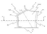
- the blade 4 includes a blade trailing edge 4b positioned on the outer peripheral side of the main plate 2, and a blade leading edge positioned on the rotation center side of the main plate 2 relative to the blade trailing edge 4b.
- Part 4a The blade leading edge 4a is located on the front side in the fan rotation direction A with respect to the blade trailing edge 4b, and the chord line connecting the blade leading edge 4a and the blade trailing edge 4b is against radiation from the rotation axis O. Is inclined.
- the range of the blade leading edge 4a close to the main plate 2 forms a blade inner circumferential front edge 4a1 substantially perpendicular to the main plate 2 in a side view.
- the range close to the side plate 3 of the blade leading edge portion 4a forms a blade side plate side front edge portion 4a2 that is inclined so as to approach the blade trailing edge portion 4b as the distance from the main plate 2 increases in a side view. Furthermore, the blade leading edge portion 4a of the blade 4 is on the side plate side of the blade inner circumferential front edge portion 4a1, and the blade side plate side front edge portion 4a2 is on the fan rotation direction A side and radially outward of the main plate 2. Curved toward.
- the blade trailing edge 4b is formed substantially perpendicular to the main plate 2 in a side view. Further, the blade trailing edge 4b is curved in the direction opposite to the fan rotation direction A on the side plate 3 side compared to the main plate 2 side. In the present embodiment, the case where the blade 4 is curved will be described, but the present invention is not limited to this. For example, you may form in a substantially flat form in planar view.
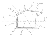
- FIG. 5 is a blade horizontal cross-sectional view orthogonal to the fan rotation axis at XX in FIGS.
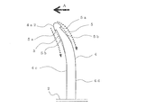
- FIG. 6 is a blade cross-sectional view substantially perpendicular to the front edge portion on the fan suction port side at YY in FIGS.
- the basic shape of the blade 4 gradually increases in thickness from the blade leading edge 4a to the outer side in the radial direction of the main plate 2. After the thickness is reached, an airfoil shape that gradually becomes thinner toward the blade trailing edge 4b is formed. Further, as shown in FIGS.
- the blade leading edge side step portion 5 is formed in the vicinity of the blade leading edge 4a.
- the blade leading edge side step portion 5 extends substantially along the blade inner circumferential side front edge portion 4a1 and the blade side plate side front edge portion 4a2, and is recessed from the recessed portion 5a and the recessed portion 5a.
- An inclined portion 5b that gradually increases the thickness of the blade 4 toward the blade trailing edge portion 4b (toward the downstream side).
- the height t1 in the thickness direction of the recess 5a is formed to have a predetermined dimension.
- the blade trailing edge side step portion 6 is formed in the vicinity of the blade trailing edge portion 4b of the blade pressure surface 4c and the blade negative pressure surface 4d.
- the blade trailing edge side step portion 6 extends substantially along the blade trailing edge portion 4b, and protrudes in the thickness direction of the blade 4, and from the protruding portion 6a toward the blade leading edge portion 4a (upstream). (Toward the side) and an inclined portion 6b that gradually reduces the thickness of the blade 4.
- the height t2 of the protrusion 6a in the thickness direction is formed to have a predetermined dimension.
- the “inclined portion 6b” corresponds to the “second inclined portion” in the present invention.
- the blade leading edge side step portion 5 is formed on both the blade pressure surface 4c and the blade negative pressure surface 4d, but the present invention is not limited to this.
- the blade leading edge side step portion 5 may be formed on at least one of the blade pressure surface 4c and the blade negative pressure surface 4d.
- the blade trailing edge side step portion 6 is formed on both the blade pressure surface 4c and the blade negative pressure surface 4d, but the present invention is not limited to this.
- the blade trailing edge side stepped portion 6 may be formed on at least one of the blade pressure surface 4c and the blade negative pressure surface 4d.
- the blade leading edge side step portion 5 is formed in the vicinity of the blade leading edge portion 4a
- the blade trailing edge side step portion 6 is formed in the vicinity of the blade trailing edge portion 4b. Only one of the blade leading edge side step portion 5 or the blade trailing edge side step portion 6 may be formed.
- the blade leading edge side step portion 5 is formed in the vicinity of the blade leading edge portion 4a of at least one of the blade pressure surface 4c and the blade negative pressure surface 4d.
- the blade leading edge side step portion 5 extends substantially along the blade inner circumferential side leading edge portion 4a1 and the blade side plate side front edge portion 4a2 and is recessed in the thickness direction of the blade 4, and the recessed portion 5a.
- an inclined portion 5b that gradually increases the thickness of the blade 4 toward the blade trailing edge portion 4b. For this reason, in the whole blade leading edge portion 4a, a pull back effect can be obtained by preventing separation when the flow reattaches at the downstream end portion of the recess portion 5a of the blade leading edge side step portion 5.
- the blade trailing edge side step portion 6 is formed in the vicinity of the blade trailing edge portion 4b of at least one of the blade pressure surface 4c and the blade negative pressure surface 4d. Then, the blade trailing edge side step portion 6 extends substantially along the blade trailing edge portion 4b, and protrudes in the thickness direction of the blade 4, and from the protruding portion 6a toward the blade leading edge portion 4a, And an inclined portion 6b for gradually reducing the thickness of the blade 4. For this reason, the wake vortex discharged from the blade trailing edge 4b to the outside is caused by the air flow on the blade 4 being pulled back to the blade trailing edge 4b by the negative pressure generated by the blade trailing edge step 6.
- the width is reduced, the turbulence is suppressed, and the pressure fluctuation is reduced. Furthermore, the turbulence generated in the flow of air flowing into the heat exchanger 16 disposed on the downstream side of the turbofan 1 can be suppressed. Therefore, an increase in noise due to the heat exchanger 16 receiving pressure fluctuations can be suppressed. As a result, a quiet air conditioner can be obtained, and a highly reliable air conditioner can be obtained that is less prone to noise deterioration even if the ventilation resistance changes due to dust or the like.
- Embodiment 2 an embodiment will be described in which at least one of the blade pressure surface 4c and the blade suction surface 4d of the blade 4 is formed of a separate member.
- the configuration of the turbo fan 1 other than the blades 4 is the same as that of the first embodiment, and the same parts are denoted by the same reference numerals.
- FIG. 7 is a view corresponding to FIG. 3 of the turbofan mounted on the air conditioner showing the second embodiment.
- FIG. 8 is a view corresponding to FIG. 4 of the turbo fan mounted on the air conditioner showing the second embodiment.
- FIG. 9 is a view corresponding to FIG. 5 of the turbo fan mounted on the air conditioner showing the second embodiment.
- FIG. 10 is a view corresponding to FIG. 6 of the turbo fan mounted on the air conditioner showing the second embodiment.
- the blade 4 of the turbofan in the present embodiment has a blade pressure surface 4c and a blade negative pressure surface 4d from the vicinity of the blade leading edge 4a to the vicinity of the blade trailing edge 4b. The region up to was constituted by another member.
- the blade pressure surface side separate member 7a is configured from the blade leading edge side step portion 5 to the blade trailing edge side step portion 6 on the blade pressure surface 4c side.
- the blade negative pressure surface side separate member 7b is configured from the blade leading edge side step portion 5 to the blade trailing edge side step portion 6 on the blade suction surface 4d side.
- the blade leading edge portion 4a, the blade trailing edge portion 4b, and the blade frame portion 7c composed of a beam member that connects the blade leading edge portion 4a and the blade trailing edge portion 4b and is thinner than the thickness of the blade 4, The blade 4 was formed by fitting and fixing the blade pressure surface side separate member 7a and the blade negative pressure surface side separate member 7b.
- blade pressure surface side separate member 7a and the blade negative pressure surface side separate member 7b are fitted into the blade frame portion 7c so that there is a gap between the blade frame portion 7c and the beam member, so that the inside of the blade 4 is obtained.
- a hollow space is formed.
- both the blade pressure surface 4c and the blade suction surface 4d are configured as separate members, but the present invention is not limited to this. At least one of the blade pressure surface 4c and the blade negative pressure surface 4d may be formed of a separate member.
- At least one of the blade pressure surface 4c and the blade negative pressure surface 4d is constituted by a separate member from the vicinity of the blade leading edge 4a to the vicinity of the blade trailing edge 4b.
- the blade leading edge 4a, the blade trailing edge 4b, and the blade frame 7c composed of a beam member that connects the blade leading edge 4a and the blade trailing edge 4b and is thinner than the thickness of the blade 4,
- the wing 4 was formed by fitting another member. For this reason, in addition to the effects of the first embodiment, the blade 4 and the separate member are not formed on the same surface, and due to a fitting failure, the separate member does not protrude from the blade leading edge 4a, and the flow is It can suppress peeling.
- a hollow space is formed inside the blade 4 by fitting another member into the blade frame portion 7c so that there is a gap between the separate member and the beam member. For this reason, the inside of the wing
- Embodiment 3 In the present embodiment, a mode in which the blade leading edge side step portion 5 and the blade trailing edge side step portion 6 are formed in a notch shape will be described.
- the configuration of the turbo fan 1 other than the blades 4 is the same as that of the first embodiment, and the same parts are denoted by the same reference numerals.
- FIG. 11 is a view corresponding to FIG. 3 of the turbo fan mounted on the air conditioner showing the third embodiment.
- FIG. 12 is a view corresponding to FIG. 4 of the turbofan mounted on the air conditioner showing the third embodiment.
- the blade 4 in the present embodiment has a recess 5 a that is substantially the same as the blade leading edge 4 a in addition to the configuration of the first embodiment.
- a notch shape that extends back and forth in the orthogonal direction is continuously formed. This notch shape has a pitch S1 along the blade leading edge 4a, a length H1 perpendicular to the blade leading edge 4a, a notch width U1 of the recess 5a, and a thickness direction of the recess 5a.
- the height t1 is formed to have a predetermined dimension. And it has the shape extended in the substantially trapezoidal shape in the side view with the slant part which the notch width tapers with respect to the direction orthogonal to blade front edge part 4a, and the flat part which follows blade front edge part 4a. Yes.
- the blade trailing edge side stepped portion 6 is formed by continuously forming a notch shape in which the protruding portion 6a is back and forth in a direction substantially orthogonal to the blade trailing edge portion 4b.
- This notch shape has a pitch S2 along the blade trailing edge 4b, a length H2 perpendicular to the blade trailing edge 4b, a notch width U2 of the protrusion 6a, and a thickness direction of the protrusion 6a.
- the height t2 is formed to have a predetermined dimension.
- both the blade leading edge side step portion 5 and the blade trailing edge side step portion 6 are notched, but the present invention is not limited to this. At least one of the blade leading edge side step portion 5 and the blade trailing edge side step portion 6 may have a notch shape.
- the blade leading edge side step portion 5 is formed by continuously forming a notch shape in which the recessed portion 5a moves back and forth in a direction substantially orthogonal to the blade leading edge portion 4a. For this reason, when the airflow flowing on the surface of the blade 4 passes over the blade leading edge side step portion 5 and reattaches to the inclined portion 5b or the blade surface by the negative pressure generated in the recess portion 5a, the direction along the blade leading edge portion 4a. Thus, the position where the negative pressure is generated becomes different between the adjacent notches. As a result, the timing of reattachment to the blade surface in the direction along the blade leading edge 4a is shifted, the regularity is lost, the pressure fluctuation is further reduced, and separation is difficult. Therefore, noise can be reduced, and a quieter turbo fan and air conditioner can be obtained.
- the blade trailing edge side stepped portion 6 is formed by continuously forming a notch shape in which the protruding portion 6a extends back and forth in a direction substantially orthogonal to the blade trailing edge portion 4b. For this reason, when the airflow flowing on the surface of the blade 4 is pulled back to the blade trailing edge 4b by the negative pressure generated by the blade trailing edge side step portion 6, a negative pressure is generated in the direction along the blade trailing edge 4b. The position becomes different between adjacent cutouts. As a result, the timing of reattachment to the blade surface is shifted in the direction along the blade trailing edge 4b, the regularity is lost, the pressure fluctuation is further reduced, and separation is difficult. Therefore, noise can be reduced, and a quieter turbo fan and air conditioner can be obtained.
- a notch shape may be continuously formed in the blade leading edge side step portion 5 and the blade trailing edge side step portion 6. good. Specifically, the joint between the blade leading edge 4a and the blade pressure surface side separate member 7a and the joint between the blade leading edge 4a and the blade suction surface side separate member 7b are notched as described above. The separate member is fitted and fixed as a shape. Further, the joint portion between the blade trailing edge portion 4b and the blade pressure surface side separate member 7a, and the joint portion between the blade trailing edge portion 4b and the blade suction surface side separate member 7b are formed as a notch shape as described above. The separate member is fitted and fixed.
- the notch shape in this Embodiment demonstrated the case where it had a substantially trapezoid shape in side view
- this invention is not limited to this.
- a substantially triangular shape with a notch taper may be used. In this way, by forming a shape in which the notch width gradually widens at least in the recess portion 5a, the flow reattached from the blade leading edge side step portion 5 to the surface of the blade 4 is not concentrated in the center of the notch, and the airflow Since the flow is diffused, noise can be suppressed.
- the turbofan according to the present invention can be widely installed in various devices including an air conditioner and a blowing means.
Abstract
Description
しかし、凹部が回転軸と略平行なため、翼前縁部のファン吸込口に面する側(側板側)では、凹部が翼前縁部に略直交する。このため、ファン吸込口に面する側(側板側)では、凹部での気流の引き戻し効果が得られない、という問題点があった。これにより、気流が翼の表面から剥離し、乱流による騒音が増加する、という問題点があった。
また、凹部の断面が略半球形状であるため、凹部の下流に流れが再付着する際、凹部の下流側角部に流れが衝突して剥離し、圧力変動が生じ、騒音が増加する、という問題点があった。
しかし、翼圧力面側部と翼負圧面側部との間にすき間が発生したり、どちらかが流れに対し突出して固定されると、突出した所で流れが剥離し、乱流による騒音が増加する、という問題点があった。
図1は実施の形態1を示す空気調和機の縦断面図である。
なお、本実施の形態では、天井埋込形の空気調和機を例に説明するが、本発明はこれに限定されるものではない。本発明は、ファン吸込側および吹出側にフィルタや熱交換器等の通風可能な圧損体を有するターボファンを搭載した空気調和機に広く適用できるものである。
また、空気調和機本体10の内部には、ターボファン1と、ターボファン1の吸込風路を形成するベルマウス14と、ターボファン1を回転駆動するファンモーター15と、ターボファン1の下流側に囲むように立設された熱交換器16とを備えている。熱交換器16は、接続配管により図示しない室外機と接続され冷媒が循環される。
また、空気調和機本体10の下面中央部には本体吸込口10cを有し、この本体吸込口10cの周囲には本体吹出口10dを有している。そして、吸込グリル11a、本体吸込口10c、本体吹出口10d、および、パネル吹出口11bが連通している。
なお、「本体吸込口10c」は、本発明における「吸込口」に相当する。
また、「パネル吹出口11b」は、本発明における「吹出口」に相当する。
また、「天板10a」および「側板10b」は、本発明における「筐体」に相当する。
熱交換器16へ向け吹き出された空気は、熱交換器16内の冷媒と熱交換して、暖房、冷房、または除湿等された空気となる。熱交換器16にて、暖房、冷房、または除湿等がされた空気は、本体吹出口10dを通過しパネル吹出口11bから部屋17へ向けて吹き出されて空調が行われる。このとき風向ベーン13により風向が制御される。
図2は図1のターボファンの斜視図である。
図3は図1のターボファンの翼1枚の負圧面側面図である。
図4は図1のターボファンの翼1枚の圧力面側面図である。
なお、図2~図4においては、理解を容易にするため、図中上方を部屋17側にしている。すなわち、図中上方から図中下方に向かって空気が吸込まれることになっている。また図2においては、理解を容易にするため、一部について側板3を外した状態を図示している。また、各図において同じ部分または相等する部分には同じ符号を付し、一部の説明を省略する。
主板2は、外周部が平坦で、中央部がファン吸込口1aへ向け突出した凸形状の回転体である。主板2の中央には、ボス2aが形成されている。このボス2aは、ファンモーター15の回転軸に固定されている。以下、主板2の当該回転軸の中心を「回転軸O」と称する。
側板3は、上縁がファン吸込口1aを形成し、ファン吸込口1aから下方になる程(主板2に近づく程)、内径が大きくなっている
そして、側板3の下縁と、これに対向する主板2と、翼4の翼後縁部4bとにより、ファン吹出口1bを形成する。
翼前縁部4aは、翼後縁部4bに対しファン回転方向Aの前側に位置し、翼前縁部4aと翼後縁部4bとを結ぶ弦線が、回転軸Oからの放射線に対して傾斜している。
翼前縁部4aの主板2に近い範囲は、側面視において、主板2にほぼ垂直の翼内周側前縁部4a1を形成している。翼前縁部4aの側板3に近い範囲は、側面視において、主板2から遠ざかる程、翼後縁部4bに近づくように傾斜した翼側板側前縁部4a2を形成している。
さらに、翼4の翼前縁部4aは、翼内周側前縁部4a1の側板側、および、翼側板側前縁部4a2が、ファン回転方向A側、かつ、主板2の径方向外側へ向け湾曲している。
翼後縁部4bは、側面視において、主板2にほぼ垂直に形成されている。
さらに、翼後縁部4bは、側板3側の方が主板2側に比べファン回転方向Aに対し逆向に湾曲している。
なお、本実施の形態においては、翼4を湾曲させた場合を説明するが本発明はこれに限るものではない。例えば平面視において略平板状に形成しても良い。
図6は図3、図4のY-Yでのファン吸込口側前縁部に略直交する翼断面図である。
図5に示すように、回転軸Oに直交するX-X断面において、翼4の基本形状は、翼前縁部4aから主板2の径方向外側に向け徐々に肉厚が厚くなり、最大肉厚となった後、翼後縁部4bへ向け徐々に薄肉となる翼形形状を形成する。
また、図5、図6に示すように、翼4のファン回転方向Aに対して前面となる翼圧力面4c、および、翼4のファン回転方向Aに対して後面となる翼負圧面4dの、翼前縁部4aの近傍に、翼前縁側段差部5を形成している。
この翼前縁側段差部5は、翼内周側前縁部4a1および翼側板側前縁部4a2にほぼ沿うように伸び、当該翼4の肉厚方向にへこむ窪み部5aと、窪み部5aから翼後縁部4bへ向かって(下流側に向かって)、当該翼4の肉厚を徐々に厚くする傾斜部5bと、から構成されている。なお、窪み部5aの肉厚方向の高さt1は、所定寸法となるように形成している。
この翼後縁側段差部6は、翼後縁部4bにほぼ沿うように伸び、当該翼4の肉厚方向に突出する突出部6aと、突出部6aから翼前縁部4aへ向かって(上流側に向かって)、当該翼4の肉厚を徐々に薄くする傾斜部6bと、から構成されている。突出部6aの肉厚方向の高さt2は、所定寸法となるように形成している。
なお、「傾斜部6b」は、本発明における「第2傾斜部」に相当する。
また、本実施の形態では、翼圧力面4cおよび翼負圧面4dの両方に、翼後縁側段差部6を形成したが、本発明はこれに限るものではない。翼圧力面4cおよび翼負圧面4dの少なくとも一方に、翼後縁側段差部6を形成するようにしても良い。
また、本実施の形態では、翼前縁部4aの近傍に翼前縁側段差部5を形成し、翼後縁部4bの近傍に翼後縁側段差部6を形成したが、これに限らず、翼前縁側段差部5、または、翼後縁側段差部6の何れか一方のみを形成するようにしても良い。
このため、翼前縁部4a全体において、翼前縁側段差部5の窪み部5aの下流端部で流れが再付着する際の剥離を防止することで引き戻し効果を得ることができる。よって、翼4の表面における気流の剥離を抑制し、乱流による騒音を低減することができる。
また、ファン吸込口1a側の通風抵抗が、例えばフィルタ12へのホコリの堆積などで増加しても、翼4の表面における気流の剥離を抑制することができる。よって、通風抵抗が増加した場合であっても低騒音が維持される。
以上の結果、静粛な空気調和機が得られると共に、ホコリ等により通風抵抗が変化しても騒音悪化しづらく信頼性が高い空気調和機が得られる。
このため、翼4表面の気流の流れが翼後縁側段差部6により生成される負圧により、翼後縁部4bに引き戻されることで、翼後縁部4bから外部へ放出される後流渦幅が縮小し、乱れが抑制され圧力変動が減少する。
さらに、ターボファン1の下流側に配設される熱交換器16への流入する空気の流れに生じる乱れを抑制することができる。よって、熱交換器16が圧力変動を受けことによる騒音の増加を抑制することができる。
以上の結果、静粛な空気調和機が得られると共に、ホコリ等により通風抵抗が変化しても騒音悪化しづらく信頼性が高い空気調和機が得られる。
本実施の形態では、翼4の翼圧力面4cおよび翼負圧面4dの少なくとも一方を別部材で構成した形態について説明する。
なお、ターボファン1の翼4以外の構成は、上記実施の形態1と同様であり、同一部分には同一の符号を付する。
図8は実施の形態2を示す空気調和機に搭載されるターボファンの図4に相当する図である。
図9は実施の形態2を示す空気調和機に搭載されるターボファンの図5に相当する図である。
図10は実施の形態2を示す空気調和機に搭載されるターボファンの図6に相当する図である。
図7~図10に示すように、本実施の形態におけるターボファンの翼4は、翼圧力面4c、および、翼負圧面4dは、翼前縁部4aの近傍から翼後縁部4bの近傍までの領域を別部材で構成した。具体的には、翼圧力面4c側の翼前縁側段差部5から翼後縁側段差部6までを翼圧力面側別部材7aで構成する。また、翼負圧面4d側の翼前縁側段差部5から翼後縁側段差部6までを翼負圧面側別部材7bで構成する。
そして、翼前縁部4a、翼後縁部4b、および、翼前縁部4aと翼後縁部4bとを結び当該翼4の厚さより肉薄な梁部材で構成される翼フレーム部7cに、翼圧力面側別部材7aと翼負圧面側別部材7bとをはめ込み固着することで一体とすることで、当該翼4を形成した。
さらに、翼圧力面側別部材7aおよび翼負圧面側別部材7bを、翼フレーム部7cの梁部材との間にすき間があくように、翼フレーム部7cにはめ込むことで、翼4の内部に中空の空間を形成している。
このため、上記実施の形態1の効果に加え、翼4と別部材とが同一面で形成されておらず、勘合不具合により、翼前縁部4aで別部材が突出することがなく、流れが剥離することを抑制できる。また、翼後縁部4bでは翼4に対し別部材がへこむことがなく、翼後縁部4bで気流が剥離することを抑制し、後流渦幅が増加することを抑制し、気流の乱れによる騒音を低減することができる。よって、高品質なターボファンおよび空気調和機が得られる。
以上の結果、本発明によれば、静粛、軽量で高品質なターボファンおよび空気調和機が得られる。
このため、翼4の内部は中空形状となり、翼4の材料を減らすことができ、軽量化を図ることができる。よって、軽量なターボファンおよび空気調和機が得られる。
本実施の形態では、翼前縁側段差部5および翼後縁側段差部6を、切り欠き形状に形成した形態について説明する。
なお、ターボファン1の翼4以外の構成は、上記実施の形態1と同様であり、同一部分には同一の符号を付する。
図12は実施の形態3を示す空気調和機に搭載されるターボファンの図4に相当する図である。
図11、図12に示すように、本実施の形態における翼4は、上記実施の形態1の構成に加え、翼前縁側段差部5は、窪み部5aが、翼前縁部4aに対し略直交方向に前後する切り欠き形状を連続して形成している。この切り欠き形状は、翼前縁部4aに沿う方向のピッチS1、翼前縁部4aに直交する方向の長さH1、窪み部5aの切り欠き幅U1、および、窪み部5aの肉厚方向の高さt1が、所定寸法となるように形成されている。そして、翼前縁部4aに直交する方向に対し、切り欠き幅が先細りする斜め部と、翼前縁部4aに沿う平坦部とで、側面視において略台形状に伸びた形状を有している。
このため、翼4の表面を流れる気流が翼前縁側段差部5を乗り越え、窪み部5aで生成される負圧により傾斜部5bや翼表面に再付着する際、翼前縁部4aに沿う方向で負圧が生成される位置が、隣り合う切り欠き部で異なるようになる。これにより、翼前縁部4aに沿う方向で翼表面に再付着するタイミングがずれ、規則性が無くなり、圧力変動がさらに小さくなり剥離しづらくなる。よって、低騒音化が可能で、より静粛なターボファンおよび空気調和機が得られる。
このため、翼4の表面を流れる気流が翼後縁側段差部6により生成される負圧により、翼後縁部4bに引き戻される際、翼後縁部4bに沿う方向で負圧が生成される位置が、隣り合う切り欠き部で異なるようになる。これにより、翼後縁部4bに沿う方向で翼表面に再付着するタイミングがずれ、規則性が無くなり、圧力変動がさらに小さくなり剥離しづらくなる。よって、低騒音化が可能で、より静粛なターボファンおよび空気調和機が得られる。
具体的には、翼前縁部4aと翼圧力面側別部材7aとの接合部、および、翼前縁部4aと翼負圧面側別部材7bとの接合部を、上述のような切り欠き形状として、当該別部材をはめ込み固着する。また、翼後縁部4bと翼圧力面側別部材7aとの接合部、および、翼後縁部4bと翼負圧面側別部材7bとの接合部を、上述のような切り欠き形状として、当該別部材をはめ込み固着する。
これにより、上記の効果に加え、万一、別部材の組立不具合等によって、翼前縁部4aより別部材が突出してしまい翼前縁部4aで気流の剥離が生じても、または、翼後縁部4bで別部材がへこみ翼後縁部4bで剥離が生じる場合であっても、切り欠き形状により剥離渦が拡散されるため、翼4の表面に再付着することで騒音の増加を抑制できる。つまり、信頼性の高いターボファンおよび空気調和機が得られる。
このように、窪み部5aで少なくとも徐々に切り欠き幅が広がる形状とすることで、翼前縁側段差部5から翼4の表面へ再付着する流れが切り欠きの中央に集中せず、気流の流れが拡散されるため、騒音を抑制することができる。
Claims (8)
- 回転駆動される円形の主板と、
前記主板に対向して配置された円環状の側板と、
両端がそれぞれ前記主板と前記側板とに接合され、前記主板の周方向に間隔をあけて配置された複数の翼と、
を備え、
前記翼は、
前記主板の外周側に位置する翼後縁部と、
前記翼後縁部よりも前記主板の回転中心側に位置する翼前縁部と、
を有し、
前記翼前縁部の前記主板に近い範囲は、前記主板にほぼ垂直の翼内周側前縁部を形成し、
前記翼前縁部の前記側板に近い範囲は、前記主板から遠ざかる程、前記翼後縁部に近づくように傾斜した翼側板側前縁部を形成し、
前記翼の回転方向に対して前面となる圧力面、および、前記翼の回転方向に対して後面となる負圧面の少なくとも一方の、前記翼前縁部の近傍に、
前記翼内周側前縁部および前記翼側板側前縁部にほぼ沿うように伸び、当該翼の肉厚方向にへこむ窪み部と、前記窪み部から前記翼後縁部へ向かって、当該翼の肉厚を徐々に厚くする傾斜部と、を有する翼前縁側段差部を形成した
ことを特徴とするターボファン。 - 前記翼後縁部は、前記主板にほぼ垂直に形成され、
前記翼の回転方向に対して前面となる圧力面、および、前記翼の回転方向に対して後面となる負圧面の少なくとも一方の、前記翼後縁部の近傍に、
前記翼後縁部にほぼ沿うように伸び、当該翼の肉厚方向に突出する突出部と、前記突出部から前記翼前縁部へ向かって、当該翼の肉厚を徐々に薄くする第2傾斜部と、を有する翼後縁側段差部を形成した
ことを特徴とする請求項1記載のターボファン。 - 前記翼の回転方向に対して前面となる圧力面、および、前記翼の回転方向に対して後面となる負圧面の少なくとも一方は、前記翼前縁部の近傍から前記翼後縁部の近傍までの領域を別部材で構成し、
前記翼前縁部、前記翼後縁部、および、前記翼前縁部と前記翼後縁部とを結び当該翼の厚さより肉薄な梁部材で構成されるフレーム部に、前記別部材をはめ込むことで、当該翼を形成した
ことを特徴とする請求項1または2に記載のターボファン。 - 前記別部材と前記梁部材との間にすき間があくように、前記フレーム部に前記別部材をはめ込むことで、前記翼の内部に中空の空間を形成した
ことを特徴とする請求項3記載のターボファン。 - 前記翼前縁側段差部は、
前記窪み部が、前記翼前縁部に対し略直交方向に前後する切り欠き形状を連続して形成し、
該切り欠き形状は、
前記翼前縁部に沿う方向のピッチ、前記翼前縁部に直交する方向の長さ、および、前記窪み部の肉厚方向の高さが、所定寸法となるように形成した
ことを特徴とする請求項1~4の何れか1項に記載のターボファン。 - 前記翼後縁側段差部は、
前記突出部が、前記翼後縁部に対し略直交方向に前後する切り欠き形状を連続して形成し、
該切り欠き形状は、
前記翼後縁部に沿う方向のピッチ、前記翼後縁部に直交する方向の長さ、および、前記突出部の肉厚方向の高さが、所定寸法となるように形成した
ことを特徴とする請求項2~5の何れか1項に記載のターボファン。 - 前記切り欠き形状は、側面視において略三角形状または台形状である
ことを特徴とする請求項5または6記載のターボファン。 - 空気を吸込む吸込口および空気を吹き出す吹出口を有する筐体と、
前記筐体内に配置された請求項1~7の何れか1項に記載のターボファンと、
前記ターボファンの前記主板を回転駆動するモーターと、
前記ターボファンの周囲に配置された熱交換器と、
を備えたことを特徴とする空気調和機。
Priority Applications (5)
| Application Number | Priority Date | Filing Date | Title |
|---|---|---|---|
| CN201180070019.8A CN103477084B (zh) | 2011-04-12 | 2011-04-12 | 涡轮风扇以及空调机 |
| EP11863403.9A EP2698543B1 (en) | 2011-04-12 | 2011-04-12 | Centrifugal fan and air conditioner |
| PCT/JP2011/002141 WO2012140690A1 (ja) | 2011-04-12 | 2011-04-12 | ターボファン、および空気調和機 |
| JP2013509663A JP5575332B2 (ja) | 2011-04-12 | 2011-04-12 | ターボファン、および空気調和機 |
| US14/004,177 US9528374B2 (en) | 2011-04-12 | 2011-04-12 | Turbofan, and air-conditioning apparatus |
Applications Claiming Priority (1)
| Application Number | Priority Date | Filing Date | Title |
|---|---|---|---|
| PCT/JP2011/002141 WO2012140690A1 (ja) | 2011-04-12 | 2011-04-12 | ターボファン、および空気調和機 |
Publications (1)
| Publication Number | Publication Date |
|---|---|
| WO2012140690A1 true WO2012140690A1 (ja) | 2012-10-18 |
Family
ID=47008908
Family Applications (1)
| Application Number | Title | Priority Date | Filing Date |
|---|---|---|---|
| PCT/JP2011/002141 WO2012140690A1 (ja) | 2011-04-12 | 2011-04-12 | ターボファン、および空気調和機 |
Country Status (5)
| Country | Link |
|---|---|
| US (1) | US9528374B2 (ja) |
| EP (1) | EP2698543B1 (ja) |
| JP (1) | JP5575332B2 (ja) |
| CN (1) | CN103477084B (ja) |
| WO (1) | WO2012140690A1 (ja) |
Cited By (5)
| Publication number | Priority date | Publication date | Assignee | Title |
|---|---|---|---|---|
| EP2846046A1 (de) * | 2013-09-10 | 2015-03-11 | Punker GmbH | Ventilatorrad |
| EP2848817A3 (en) * | 2013-09-12 | 2015-08-05 | Mitsubishi Electric Corporation | Centrifugal fan and air-conditioning apparatus |
| JP2015183604A (ja) * | 2014-03-25 | 2015-10-22 | パナソニックIpマネジメント株式会社 | 送風装置 |
| WO2016067409A1 (ja) * | 2014-10-30 | 2016-05-06 | 三菱電機株式会社 | ターボファンおよび空気調和装置用室内機 |
| JP2016160905A (ja) * | 2015-03-05 | 2016-09-05 | パナソニックIpマネジメント株式会社 | 遠心ファン |
Families Citing this family (11)
| Publication number | Priority date | Publication date | Assignee | Title |
|---|---|---|---|---|
| WO2014061094A1 (ja) * | 2012-10-16 | 2014-04-24 | 三菱電機株式会社 | ターボファンおよび空気調和機 |
| WO2014150685A1 (en) * | 2013-03-15 | 2014-09-25 | Regal Beloit America, Inc. | Fan |
| EP3098453B1 (en) * | 2015-04-20 | 2018-05-23 | Mitsubishi Electric Corporation | Turbofan and air-conditioning device |
| ITUB20152807A1 (it) * | 2015-08-03 | 2017-02-03 | Ma Ti Ka S R L | Ventola per forni per la cottura di alimenti |
| JP6650591B2 (ja) * | 2015-10-14 | 2020-02-19 | パナソニックIpマネジメント株式会社 | 空気調和機の室内ユニット |
| JP2017078386A (ja) * | 2015-10-22 | 2017-04-27 | パナソニックIpマネジメント株式会社 | 遠心ファン |
| JP6635077B2 (ja) * | 2017-03-13 | 2020-01-22 | 株式会社デンソー | 遠心送風機 |
| WO2019021391A1 (ja) * | 2017-07-26 | 2019-01-31 | 三菱電機株式会社 | 空気調和機 |
| US10415584B2 (en) * | 2017-10-20 | 2019-09-17 | Minebea Mitsumi Inc. | Impeller and fan using the same |
| JP7003902B2 (ja) * | 2018-12-14 | 2022-02-04 | 株式会社デンソー | 遠心ファン、遠心送風機 |
| EP4034769A1 (de) | 2020-03-10 | 2022-08-03 | ebm-papst Mulfingen GmbH & Co. KG | Ventilator und ventilatorflügel |
Citations (6)
| Publication number | Priority date | Publication date | Assignee | Title |
|---|---|---|---|---|
| JPH07310696A (ja) * | 1994-05-13 | 1995-11-28 | Daikin Ind Ltd | 送風機 |
| JP2669448B2 (ja) | 1993-06-15 | 1997-10-27 | 松下冷機株式会社 | 遠心送風機の羽根車 |
| JPH09280196A (ja) * | 1996-04-11 | 1997-10-28 | Daikin Ind Ltd | 送風機 |
| JP2006017063A (ja) * | 2004-07-05 | 2006-01-19 | Matsushita Electric Ind Co Ltd | 送風機 |
| JP2008144667A (ja) * | 2006-12-11 | 2008-06-26 | Daikin Ind Ltd | 送風機の羽根車 |
| JP4432474B2 (ja) | 2003-11-27 | 2010-03-17 | ダイキン工業株式会社 | 遠心送風機の羽根車及びそれを備えた遠心送風機 |
Family Cites Families (7)
| Publication number | Priority date | Publication date | Assignee | Title |
|---|---|---|---|---|
| JPS63160400U (ja) * | 1987-04-09 | 1988-10-20 | ||
| US6739835B2 (en) * | 2001-08-24 | 2004-05-25 | Lg Electronics Inc. | Blade part in turbofan |
| AU2003284610B2 (en) * | 2002-12-16 | 2006-11-16 | Daikin Industries, Ltd. | Centrifugal fan, and air conditioner provided therewith |
| KR20040104772A (ko) * | 2003-06-03 | 2004-12-13 | 삼성전자주식회사 | 터보팬 및 이를 갖춘 공기조화기 |
| JP3995010B2 (ja) | 2005-09-28 | 2007-10-24 | ダイキン工業株式会社 | 多翼送風機の羽根車及びその製造方法 |
| JP4840343B2 (ja) * | 2007-11-30 | 2011-12-21 | 三菱電機株式会社 | 貫流ファン及び空気調和機 |
| JPWO2009139422A1 (ja) * | 2008-05-14 | 2011-09-22 | ダイキン工業株式会社 | 遠心送風機 |
-
2011
- 2011-04-12 EP EP11863403.9A patent/EP2698543B1/en active Active
- 2011-04-12 WO PCT/JP2011/002141 patent/WO2012140690A1/ja active Application Filing
- 2011-04-12 US US14/004,177 patent/US9528374B2/en active Active
- 2011-04-12 CN CN201180070019.8A patent/CN103477084B/zh active Active
- 2011-04-12 JP JP2013509663A patent/JP5575332B2/ja active Active
Patent Citations (6)
| Publication number | Priority date | Publication date | Assignee | Title |
|---|---|---|---|---|
| JP2669448B2 (ja) | 1993-06-15 | 1997-10-27 | 松下冷機株式会社 | 遠心送風機の羽根車 |
| JPH07310696A (ja) * | 1994-05-13 | 1995-11-28 | Daikin Ind Ltd | 送風機 |
| JPH09280196A (ja) * | 1996-04-11 | 1997-10-28 | Daikin Ind Ltd | 送風機 |
| JP4432474B2 (ja) | 2003-11-27 | 2010-03-17 | ダイキン工業株式会社 | 遠心送風機の羽根車及びそれを備えた遠心送風機 |
| JP2006017063A (ja) * | 2004-07-05 | 2006-01-19 | Matsushita Electric Ind Co Ltd | 送風機 |
| JP2008144667A (ja) * | 2006-12-11 | 2008-06-26 | Daikin Ind Ltd | 送風機の羽根車 |
Non-Patent Citations (1)
| Title |
|---|
| See also references of EP2698543A4 |
Cited By (9)
| Publication number | Priority date | Publication date | Assignee | Title |
|---|---|---|---|---|
| EP2846046A1 (de) * | 2013-09-10 | 2015-03-11 | Punker GmbH | Ventilatorrad |
| CN104421200A (zh) * | 2013-09-10 | 2015-03-18 | 庞克有限公司 | 风扇叶轮 |
| CN104421200B (zh) * | 2013-09-10 | 2018-05-18 | 庞克有限公司 | 风扇叶轮 |
| EP2848817A3 (en) * | 2013-09-12 | 2015-08-05 | Mitsubishi Electric Corporation | Centrifugal fan and air-conditioning apparatus |
| JP2015183604A (ja) * | 2014-03-25 | 2015-10-22 | パナソニックIpマネジメント株式会社 | 送風装置 |
| WO2016067409A1 (ja) * | 2014-10-30 | 2016-05-06 | 三菱電機株式会社 | ターボファンおよび空気調和装置用室内機 |
| JPWO2016067409A1 (ja) * | 2014-10-30 | 2017-04-27 | 三菱電機株式会社 | ターボファンおよび空気調和装置用室内機 |
| US10400605B2 (en) | 2014-10-30 | 2019-09-03 | Mitsubishi Electric Corporation | Turbofan and indoor unit for air conditioning apparatus |
| JP2016160905A (ja) * | 2015-03-05 | 2016-09-05 | パナソニックIpマネジメント株式会社 | 遠心ファン |
Also Published As
| Publication number | Publication date |
|---|---|
| US20140023501A1 (en) | 2014-01-23 |
| EP2698543A4 (en) | 2014-09-24 |
| JPWO2012140690A1 (ja) | 2014-07-28 |
| CN103477084B (zh) | 2017-11-17 |
| EP2698543A1 (en) | 2014-02-19 |
| US9528374B2 (en) | 2016-12-27 |
| JP5575332B2 (ja) | 2014-08-20 |
| EP2698543B1 (en) | 2017-10-11 |
| CN103477084A (zh) | 2013-12-25 |
Similar Documents
| Publication | Publication Date | Title |
|---|---|---|
| JP5575332B2 (ja) | ターボファン、および空気調和機 | |
| KR101210696B1 (ko) | 원심팬 | |
| WO2020077814A1 (zh) | 对旋风扇 | |
| AU2006276567B2 (en) | Axial flow fan | |
| WO2009128299A1 (ja) | ターボファンおよび空気調和機 | |
| JP4840343B2 (ja) | 貫流ファン及び空気調和機 | |
| WO2014061642A1 (ja) | ターボファンおよび空気調和機 | |
| EP3034885B1 (en) | Centrifugal fan and air conditioner provided with the same | |
| KR100709819B1 (ko) | 횡류팬과 횡류팬을 구비한 공기조화기의 실내기 | |
| JP5066835B2 (ja) | 遠心ファン及びこれを用いた空気調和機 | |
| JP5879363B2 (ja) | 多翼ファン及びこれを備えた空気調和機 | |
| WO2011114375A1 (ja) | 貫流ファン及び空気調和機 | |
| JP2002235695A (ja) | ターボファン、およびターボファンを用いた送風装置、空気調和機 | |
| JP5151331B2 (ja) | 多翼羽根車および多翼送風機 | |
| JP2008223741A (ja) | 遠心送風機 | |
| JPH09126190A (ja) | 遠心式送風機 | |
| CN110914553B (zh) | 叶轮、送风机及空调装置 | |
| JP2004011423A (ja) | 送風部の気流制御構造 | |
| JP2010242597A (ja) | 軸流送風機及び空気調和機 | |
| JP4872997B2 (ja) | 送風機及び該送風機を備えた空気調和機 | |
| JP2000283518A (ja) | エアカ−テン | |
| JP2011196387A (ja) | 貫流ファン及び空気調和機 | |
| JP2762884B2 (ja) | 送風機構 | |
| JP6625213B2 (ja) | 多翼ファン及び空気調和機 | |
| JP2002054595A (ja) | 遠心ファン |
Legal Events
| Date | Code | Title | Description |
|---|---|---|---|
| 121 | Ep: the epo has been informed by wipo that ep was designated in this application |
Ref document number: 11863403 Country of ref document: EP Kind code of ref document: A1 |
|
| WWE | Wipo information: entry into national phase |
Ref document number: 14004177 Country of ref document: US |
|
| ENP | Entry into the national phase |
Ref document number: 2013509663 Country of ref document: JP Kind code of ref document: A |
|
| NENP | Non-entry into the national phase |
Ref country code: DE |
|
| REEP | Request for entry into the european phase |
Ref document number: 2011863403 Country of ref document: EP |