WO2012137985A1 - 接合体の製造方法 - Google Patents
接合体の製造方法 Download PDFInfo
- Publication number
- WO2012137985A1 WO2012137985A1 PCT/JP2012/060088 JP2012060088W WO2012137985A1 WO 2012137985 A1 WO2012137985 A1 WO 2012137985A1 JP 2012060088 W JP2012060088 W JP 2012060088W WO 2012137985 A1 WO2012137985 A1 WO 2012137985A1
- Authority
- WO
- WIPO (PCT)
- Prior art keywords
- electrode
- electrodes
- thermoplastic resin
- composite materials
- composite material
- Prior art date
Links
Images


Classifications
-
- B—PERFORMING OPERATIONS; TRANSPORTING
- B23—MACHINE TOOLS; METAL-WORKING NOT OTHERWISE PROVIDED FOR
- B23K—SOLDERING OR UNSOLDERING; WELDING; CLADDING OR PLATING BY SOLDERING OR WELDING; CUTTING BY APPLYING HEAT LOCALLY, e.g. FLAME CUTTING; WORKING BY LASER BEAM
- B23K11/00—Resistance welding; Severing by resistance heating
- B23K11/06—Resistance welding; Severing by resistance heating using roller electrodes
- B23K11/061—Resistance welding; Severing by resistance heating using roller electrodes for welding rectilinear seams
-
- B—PERFORMING OPERATIONS; TRANSPORTING
- B29—WORKING OF PLASTICS; WORKING OF SUBSTANCES IN A PLASTIC STATE IN GENERAL
- B29C—SHAPING OR JOINING OF PLASTICS; SHAPING OF MATERIAL IN A PLASTIC STATE, NOT OTHERWISE PROVIDED FOR; AFTER-TREATMENT OF THE SHAPED PRODUCTS, e.g. REPAIRING
- B29C65/00—Joining or sealing of preformed parts, e.g. welding of plastics materials; Apparatus therefor
- B29C65/02—Joining or sealing of preformed parts, e.g. welding of plastics materials; Apparatus therefor by heating, with or without pressure
-
- B—PERFORMING OPERATIONS; TRANSPORTING
- B32—LAYERED PRODUCTS
- B32B—LAYERED PRODUCTS, i.e. PRODUCTS BUILT-UP OF STRATA OF FLAT OR NON-FLAT, e.g. CELLULAR OR HONEYCOMB, FORM
- B32B27/00—Layered products comprising a layer of synthetic resin
- B32B27/34—Layered products comprising a layer of synthetic resin comprising polyamides
-
- B—PERFORMING OPERATIONS; TRANSPORTING
- B23—MACHINE TOOLS; METAL-WORKING NOT OTHERWISE PROVIDED FOR
- B23K—SOLDERING OR UNSOLDERING; WELDING; CLADDING OR PLATING BY SOLDERING OR WELDING; CUTTING BY APPLYING HEAT LOCALLY, e.g. FLAME CUTTING; WORKING BY LASER BEAM
- B23K11/00—Resistance welding; Severing by resistance heating
- B23K11/06—Resistance welding; Severing by resistance heating using roller electrodes
-
- B—PERFORMING OPERATIONS; TRANSPORTING
- B23—MACHINE TOOLS; METAL-WORKING NOT OTHERWISE PROVIDED FOR
- B23K—SOLDERING OR UNSOLDERING; WELDING; CLADDING OR PLATING BY SOLDERING OR WELDING; CUTTING BY APPLYING HEAT LOCALLY, e.g. FLAME CUTTING; WORKING BY LASER BEAM
- B23K11/00—Resistance welding; Severing by resistance heating
- B23K11/10—Spot welding; Stitch welding
- B23K11/11—Spot welding
- B23K11/115—Spot welding by means of two electrodes placed opposite one another on both sides of the welded parts
-
- B—PERFORMING OPERATIONS; TRANSPORTING
- B23—MACHINE TOOLS; METAL-WORKING NOT OTHERWISE PROVIDED FOR
- B23K—SOLDERING OR UNSOLDERING; WELDING; CLADDING OR PLATING BY SOLDERING OR WELDING; CUTTING BY APPLYING HEAT LOCALLY, e.g. FLAME CUTTING; WORKING BY LASER BEAM
- B23K11/00—Resistance welding; Severing by resistance heating
- B23K11/16—Resistance welding; Severing by resistance heating taking account of the properties of the material to be welded
-
- B—PERFORMING OPERATIONS; TRANSPORTING
- B23—MACHINE TOOLS; METAL-WORKING NOT OTHERWISE PROVIDED FOR
- B23K—SOLDERING OR UNSOLDERING; WELDING; CLADDING OR PLATING BY SOLDERING OR WELDING; CUTTING BY APPLYING HEAT LOCALLY, e.g. FLAME CUTTING; WORKING BY LASER BEAM
- B23K11/00—Resistance welding; Severing by resistance heating
- B23K11/30—Features relating to electrodes
- B23K11/31—Electrode holders and actuating devices therefor
- B23K11/314—Spot welding guns, e.g. mounted on robots
-
- B—PERFORMING OPERATIONS; TRANSPORTING
- B29—WORKING OF PLASTICS; WORKING OF SUBSTANCES IN A PLASTIC STATE IN GENERAL
- B29C—SHAPING OR JOINING OF PLASTICS; SHAPING OF MATERIAL IN A PLASTIC STATE, NOT OTHERWISE PROVIDED FOR; AFTER-TREATMENT OF THE SHAPED PRODUCTS, e.g. REPAIRING
- B29C65/00—Joining or sealing of preformed parts, e.g. welding of plastics materials; Apparatus therefor
- B29C65/02—Joining or sealing of preformed parts, e.g. welding of plastics materials; Apparatus therefor by heating, with or without pressure
- B29C65/34—Joining or sealing of preformed parts, e.g. welding of plastics materials; Apparatus therefor by heating, with or without pressure using heated elements which remain in the joint, e.g. "verlorenes Schweisselement"
- B29C65/3404—Joining or sealing of preformed parts, e.g. welding of plastics materials; Apparatus therefor by heating, with or without pressure using heated elements which remain in the joint, e.g. "verlorenes Schweisselement" characterised by the type of heated elements which remain in the joint
- B29C65/3408—Joining or sealing of preformed parts, e.g. welding of plastics materials; Apparatus therefor by heating, with or without pressure using heated elements which remain in the joint, e.g. "verlorenes Schweisselement" characterised by the type of heated elements which remain in the joint comprising single particles, e.g. fillers or discontinuous fibre-reinforcements
- B29C65/3416—Joining or sealing of preformed parts, e.g. welding of plastics materials; Apparatus therefor by heating, with or without pressure using heated elements which remain in the joint, e.g. "verlorenes Schweisselement" characterised by the type of heated elements which remain in the joint comprising single particles, e.g. fillers or discontinuous fibre-reinforcements comprising discontinuous fibre-reinforcements
-
- B—PERFORMING OPERATIONS; TRANSPORTING
- B29—WORKING OF PLASTICS; WORKING OF SUBSTANCES IN A PLASTIC STATE IN GENERAL
- B29C—SHAPING OR JOINING OF PLASTICS; SHAPING OF MATERIAL IN A PLASTIC STATE, NOT OTHERWISE PROVIDED FOR; AFTER-TREATMENT OF THE SHAPED PRODUCTS, e.g. REPAIRING
- B29C65/00—Joining or sealing of preformed parts, e.g. welding of plastics materials; Apparatus therefor
- B29C65/02—Joining or sealing of preformed parts, e.g. welding of plastics materials; Apparatus therefor by heating, with or without pressure
- B29C65/34—Joining or sealing of preformed parts, e.g. welding of plastics materials; Apparatus therefor by heating, with or without pressure using heated elements which remain in the joint, e.g. "verlorenes Schweisselement"
- B29C65/3468—Joining or sealing of preformed parts, e.g. welding of plastics materials; Apparatus therefor by heating, with or without pressure using heated elements which remain in the joint, e.g. "verlorenes Schweisselement" characterised by the means for supplying heat to said heated elements which remain in the join, e.g. special electrical connectors of windings
-
- B—PERFORMING OPERATIONS; TRANSPORTING
- B29—WORKING OF PLASTICS; WORKING OF SUBSTANCES IN A PLASTIC STATE IN GENERAL
- B29C—SHAPING OR JOINING OF PLASTICS; SHAPING OF MATERIAL IN A PLASTIC STATE, NOT OTHERWISE PROVIDED FOR; AFTER-TREATMENT OF THE SHAPED PRODUCTS, e.g. REPAIRING
- B29C65/00—Joining or sealing of preformed parts, e.g. welding of plastics materials; Apparatus therefor
- B29C65/02—Joining or sealing of preformed parts, e.g. welding of plastics materials; Apparatus therefor by heating, with or without pressure
- B29C65/34—Joining or sealing of preformed parts, e.g. welding of plastics materials; Apparatus therefor by heating, with or without pressure using heated elements which remain in the joint, e.g. "verlorenes Schweisselement"
- B29C65/3472—Joining or sealing of preformed parts, e.g. welding of plastics materials; Apparatus therefor by heating, with or without pressure using heated elements which remain in the joint, e.g. "verlorenes Schweisselement" characterised by the composition of the heated elements which remain in the joint
- B29C65/3484—Joining or sealing of preformed parts, e.g. welding of plastics materials; Apparatus therefor by heating, with or without pressure using heated elements which remain in the joint, e.g. "verlorenes Schweisselement" characterised by the composition of the heated elements which remain in the joint being non-metallic
- B29C65/3492—Joining or sealing of preformed parts, e.g. welding of plastics materials; Apparatus therefor by heating, with or without pressure using heated elements which remain in the joint, e.g. "verlorenes Schweisselement" characterised by the composition of the heated elements which remain in the joint being non-metallic being carbon
-
- B—PERFORMING OPERATIONS; TRANSPORTING
- B29—WORKING OF PLASTICS; WORKING OF SUBSTANCES IN A PLASTIC STATE IN GENERAL
- B29C—SHAPING OR JOINING OF PLASTICS; SHAPING OF MATERIAL IN A PLASTIC STATE, NOT OTHERWISE PROVIDED FOR; AFTER-TREATMENT OF THE SHAPED PRODUCTS, e.g. REPAIRING
- B29C66/00—General aspects of processes or apparatus for joining preformed parts
- B29C66/01—General aspects dealing with the joint area or with the area to be joined
- B29C66/05—Particular design of joint configurations
- B29C66/10—Particular design of joint configurations particular design of the joint cross-sections
- B29C66/11—Joint cross-sections comprising a single joint-segment, i.e. one of the parts to be joined comprising a single joint-segment in the joint cross-section
- B29C66/112—Single lapped joints
- B29C66/1122—Single lap to lap joints, i.e. overlap joints
-
- B—PERFORMING OPERATIONS; TRANSPORTING
- B29—WORKING OF PLASTICS; WORKING OF SUBSTANCES IN A PLASTIC STATE IN GENERAL
- B29C—SHAPING OR JOINING OF PLASTICS; SHAPING OF MATERIAL IN A PLASTIC STATE, NOT OTHERWISE PROVIDED FOR; AFTER-TREATMENT OF THE SHAPED PRODUCTS, e.g. REPAIRING
- B29C66/00—General aspects of processes or apparatus for joining preformed parts
- B29C66/01—General aspects dealing with the joint area or with the area to be joined
- B29C66/05—Particular design of joint configurations
- B29C66/10—Particular design of joint configurations particular design of the joint cross-sections
- B29C66/13—Single flanged joints; Fin-type joints; Single hem joints; Edge joints; Interpenetrating fingered joints; Other specific particular designs of joint cross-sections not provided for in groups B29C66/11 - B29C66/12
- B29C66/131—Single flanged joints, i.e. one of the parts to be joined being rigid and flanged in the joint area
- B29C66/1312—Single flange to flange joints, the parts to be joined being rigid
-
- B—PERFORMING OPERATIONS; TRANSPORTING
- B29—WORKING OF PLASTICS; WORKING OF SUBSTANCES IN A PLASTIC STATE IN GENERAL
- B29C—SHAPING OR JOINING OF PLASTICS; SHAPING OF MATERIAL IN A PLASTIC STATE, NOT OTHERWISE PROVIDED FOR; AFTER-TREATMENT OF THE SHAPED PRODUCTS, e.g. REPAIRING
- B29C66/00—General aspects of processes or apparatus for joining preformed parts
- B29C66/01—General aspects dealing with the joint area or with the area to be joined
- B29C66/05—Particular design of joint configurations
- B29C66/20—Particular design of joint configurations particular design of the joint lines, e.g. of the weld lines
- B29C66/21—Particular design of joint configurations particular design of the joint lines, e.g. of the weld lines said joint lines being formed by a single dot or dash or by several dots or dashes, i.e. spot joining or spot welding
-
- B—PERFORMING OPERATIONS; TRANSPORTING
- B29—WORKING OF PLASTICS; WORKING OF SUBSTANCES IN A PLASTIC STATE IN GENERAL
- B29C—SHAPING OR JOINING OF PLASTICS; SHAPING OF MATERIAL IN A PLASTIC STATE, NOT OTHERWISE PROVIDED FOR; AFTER-TREATMENT OF THE SHAPED PRODUCTS, e.g. REPAIRING
- B29C66/00—General aspects of processes or apparatus for joining preformed parts
- B29C66/01—General aspects dealing with the joint area or with the area to be joined
- B29C66/343—Making tension-free or wrinkle-free joints
-
- B—PERFORMING OPERATIONS; TRANSPORTING
- B29—WORKING OF PLASTICS; WORKING OF SUBSTANCES IN A PLASTIC STATE IN GENERAL
- B29C—SHAPING OR JOINING OF PLASTICS; SHAPING OF MATERIAL IN A PLASTIC STATE, NOT OTHERWISE PROVIDED FOR; AFTER-TREATMENT OF THE SHAPED PRODUCTS, e.g. REPAIRING
- B29C66/00—General aspects of processes or apparatus for joining preformed parts
- B29C66/40—General aspects of joining substantially flat articles, e.g. plates, sheets or web-like materials; Making flat seams in tubular or hollow articles; Joining single elements to substantially flat surfaces
- B29C66/41—Joining substantially flat articles ; Making flat seams in tubular or hollow articles
- B29C66/43—Joining a relatively small portion of the surface of said articles
-
- B—PERFORMING OPERATIONS; TRANSPORTING
- B29—WORKING OF PLASTICS; WORKING OF SUBSTANCES IN A PLASTIC STATE IN GENERAL
- B29C—SHAPING OR JOINING OF PLASTICS; SHAPING OF MATERIAL IN A PLASTIC STATE, NOT OTHERWISE PROVIDED FOR; AFTER-TREATMENT OF THE SHAPED PRODUCTS, e.g. REPAIRING
- B29C66/00—General aspects of processes or apparatus for joining preformed parts
- B29C66/50—General aspects of joining tubular articles; General aspects of joining long products, i.e. bars or profiled elements; General aspects of joining single elements to tubular articles, hollow articles or bars; General aspects of joining several hollow-preforms to form hollow or tubular articles
- B29C66/51—Joining tubular articles, profiled elements or bars; Joining single elements to tubular articles, hollow articles or bars; Joining several hollow-preforms to form hollow or tubular articles
- B29C66/54—Joining several hollow-preforms, e.g. half-shells, to form hollow articles, e.g. for making balls, containers; Joining several hollow-preforms, e.g. half-cylinders, to form tubular articles
- B29C66/547—Joining several hollow-preforms, e.g. half-cylinders, to form tubular articles, e.g. endless tubes
-
- B—PERFORMING OPERATIONS; TRANSPORTING
- B29—WORKING OF PLASTICS; WORKING OF SUBSTANCES IN A PLASTIC STATE IN GENERAL
- B29C—SHAPING OR JOINING OF PLASTICS; SHAPING OF MATERIAL IN A PLASTIC STATE, NOT OTHERWISE PROVIDED FOR; AFTER-TREATMENT OF THE SHAPED PRODUCTS, e.g. REPAIRING
- B29C66/00—General aspects of processes or apparatus for joining preformed parts
- B29C66/70—General aspects of processes or apparatus for joining preformed parts characterised by the composition, physical properties or the structure of the material of the parts to be joined; Joining with non-plastics material
- B29C66/72—General aspects of processes or apparatus for joining preformed parts characterised by the composition, physical properties or the structure of the material of the parts to be joined; Joining with non-plastics material characterised by the structure of the material of the parts to be joined
- B29C66/721—Fibre-reinforced materials
- B29C66/7212—Fibre-reinforced materials characterised by the composition of the fibres
-
- B—PERFORMING OPERATIONS; TRANSPORTING
- B29—WORKING OF PLASTICS; WORKING OF SUBSTANCES IN A PLASTIC STATE IN GENERAL
- B29C—SHAPING OR JOINING OF PLASTICS; SHAPING OF MATERIAL IN A PLASTIC STATE, NOT OTHERWISE PROVIDED FOR; AFTER-TREATMENT OF THE SHAPED PRODUCTS, e.g. REPAIRING
- B29C66/00—General aspects of processes or apparatus for joining preformed parts
- B29C66/70—General aspects of processes or apparatus for joining preformed parts characterised by the composition, physical properties or the structure of the material of the parts to be joined; Joining with non-plastics material
- B29C66/72—General aspects of processes or apparatus for joining preformed parts characterised by the composition, physical properties or the structure of the material of the parts to be joined; Joining with non-plastics material characterised by the structure of the material of the parts to be joined
- B29C66/721—Fibre-reinforced materials
- B29C66/7214—Fibre-reinforced materials characterised by the length of the fibres
- B29C66/72143—Fibres of discontinuous lengths
-
- B—PERFORMING OPERATIONS; TRANSPORTING
- B29—WORKING OF PLASTICS; WORKING OF SUBSTANCES IN A PLASTIC STATE IN GENERAL
- B29C—SHAPING OR JOINING OF PLASTICS; SHAPING OF MATERIAL IN A PLASTIC STATE, NOT OTHERWISE PROVIDED FOR; AFTER-TREATMENT OF THE SHAPED PRODUCTS, e.g. REPAIRING
- B29C66/00—General aspects of processes or apparatus for joining preformed parts
- B29C66/70—General aspects of processes or apparatus for joining preformed parts characterised by the composition, physical properties or the structure of the material of the parts to be joined; Joining with non-plastics material
- B29C66/73—General aspects of processes or apparatus for joining preformed parts characterised by the composition, physical properties or the structure of the material of the parts to be joined; Joining with non-plastics material characterised by the intensive physical properties of the material of the parts to be joined, by the optical properties of the material of the parts to be joined, by the extensive physical properties of the parts to be joined, by the state of the material of the parts to be joined or by the material of the parts to be joined being a thermoplastic or a thermoset
- B29C66/731—General aspects of processes or apparatus for joining preformed parts characterised by the composition, physical properties or the structure of the material of the parts to be joined; Joining with non-plastics material characterised by the intensive physical properties of the material of the parts to be joined, by the optical properties of the material of the parts to be joined, by the extensive physical properties of the parts to be joined, by the state of the material of the parts to be joined or by the material of the parts to be joined being a thermoplastic or a thermoset characterised by the intensive physical properties of the material of the parts to be joined
- B29C66/7314—Electrical and dielectric properties
- B29C66/73141—Electrical conductivity
-
- B—PERFORMING OPERATIONS; TRANSPORTING
- B29—WORKING OF PLASTICS; WORKING OF SUBSTANCES IN A PLASTIC STATE IN GENERAL
- B29C—SHAPING OR JOINING OF PLASTICS; SHAPING OF MATERIAL IN A PLASTIC STATE, NOT OTHERWISE PROVIDED FOR; AFTER-TREATMENT OF THE SHAPED PRODUCTS, e.g. REPAIRING
- B29C66/00—General aspects of processes or apparatus for joining preformed parts
- B29C66/70—General aspects of processes or apparatus for joining preformed parts characterised by the composition, physical properties or the structure of the material of the parts to be joined; Joining with non-plastics material
- B29C66/73—General aspects of processes or apparatus for joining preformed parts characterised by the composition, physical properties or the structure of the material of the parts to be joined; Joining with non-plastics material characterised by the intensive physical properties of the material of the parts to be joined, by the optical properties of the material of the parts to be joined, by the extensive physical properties of the parts to be joined, by the state of the material of the parts to be joined or by the material of the parts to be joined being a thermoplastic or a thermoset
- B29C66/739—General aspects of processes or apparatus for joining preformed parts characterised by the composition, physical properties or the structure of the material of the parts to be joined; Joining with non-plastics material characterised by the intensive physical properties of the material of the parts to be joined, by the optical properties of the material of the parts to be joined, by the extensive physical properties of the parts to be joined, by the state of the material of the parts to be joined or by the material of the parts to be joined being a thermoplastic or a thermoset characterised by the material of the parts to be joined being a thermoplastic or a thermoset
- B29C66/7392—General aspects of processes or apparatus for joining preformed parts characterised by the composition, physical properties or the structure of the material of the parts to be joined; Joining with non-plastics material characterised by the intensive physical properties of the material of the parts to be joined, by the optical properties of the material of the parts to be joined, by the extensive physical properties of the parts to be joined, by the state of the material of the parts to be joined or by the material of the parts to be joined being a thermoplastic or a thermoset characterised by the material of the parts to be joined being a thermoplastic or a thermoset characterised by the material of at least one of the parts being a thermoplastic
- B29C66/73921—General aspects of processes or apparatus for joining preformed parts characterised by the composition, physical properties or the structure of the material of the parts to be joined; Joining with non-plastics material characterised by the intensive physical properties of the material of the parts to be joined, by the optical properties of the material of the parts to be joined, by the extensive physical properties of the parts to be joined, by the state of the material of the parts to be joined or by the material of the parts to be joined being a thermoplastic or a thermoset characterised by the material of the parts to be joined being a thermoplastic or a thermoset characterised by the material of at least one of the parts being a thermoplastic characterised by the materials of both parts being thermoplastics
-
- B—PERFORMING OPERATIONS; TRANSPORTING
- B29—WORKING OF PLASTICS; WORKING OF SUBSTANCES IN A PLASTIC STATE IN GENERAL
- B29C—SHAPING OR JOINING OF PLASTICS; SHAPING OF MATERIAL IN A PLASTIC STATE, NOT OTHERWISE PROVIDED FOR; AFTER-TREATMENT OF THE SHAPED PRODUCTS, e.g. REPAIRING
- B29C66/00—General aspects of processes or apparatus for joining preformed parts
- B29C66/80—General aspects of machine operations or constructions and parts thereof
- B29C66/81—General aspects of the pressing elements, i.e. the elements applying pressure on the parts to be joined in the area to be joined, e.g. the welding jaws or clamps
- B29C66/812—General aspects of the pressing elements, i.e. the elements applying pressure on the parts to be joined in the area to be joined, e.g. the welding jaws or clamps characterised by the composition, by the structure, by the intensive physical properties or by the optical properties of the material constituting the pressing elements, e.g. constituting the welding jaws or clamps
- B29C66/8126—General aspects of the pressing elements, i.e. the elements applying pressure on the parts to be joined in the area to be joined, e.g. the welding jaws or clamps characterised by the composition, by the structure, by the intensive physical properties or by the optical properties of the material constituting the pressing elements, e.g. constituting the welding jaws or clamps characterised by the intensive physical properties or by the optical properties of the material constituting the pressing elements, e.g. constituting the welding jaws or clamps
- B29C66/81261—Thermal properties, e.g. thermal conductivity, thermal expansion coefficient
-
- B—PERFORMING OPERATIONS; TRANSPORTING
- B29—WORKING OF PLASTICS; WORKING OF SUBSTANCES IN A PLASTIC STATE IN GENERAL
- B29C—SHAPING OR JOINING OF PLASTICS; SHAPING OF MATERIAL IN A PLASTIC STATE, NOT OTHERWISE PROVIDED FOR; AFTER-TREATMENT OF THE SHAPED PRODUCTS, e.g. REPAIRING
- B29C66/00—General aspects of processes or apparatus for joining preformed parts
- B29C66/80—General aspects of machine operations or constructions and parts thereof
- B29C66/81—General aspects of the pressing elements, i.e. the elements applying pressure on the parts to be joined in the area to be joined, e.g. the welding jaws or clamps
- B29C66/818—General aspects of the pressing elements, i.e. the elements applying pressure on the parts to be joined in the area to be joined, e.g. the welding jaws or clamps characterised by the cooling constructional aspects, or by the thermal or electrical insulating or conducting constructional aspects of the welding jaws or of the clamps ; comprising means for compensating for the thermal expansion of the welding jaws or of the clamps
- B29C66/8187—General aspects of the pressing elements, i.e. the elements applying pressure on the parts to be joined in the area to be joined, e.g. the welding jaws or clamps characterised by the cooling constructional aspects, or by the thermal or electrical insulating or conducting constructional aspects of the welding jaws or of the clamps ; comprising means for compensating for the thermal expansion of the welding jaws or of the clamps characterised by the electrical insulating constructional aspects
- B29C66/81875—General aspects of the pressing elements, i.e. the elements applying pressure on the parts to be joined in the area to be joined, e.g. the welding jaws or clamps characterised by the cooling constructional aspects, or by the thermal or electrical insulating or conducting constructional aspects of the welding jaws or of the clamps ; comprising means for compensating for the thermal expansion of the welding jaws or of the clamps characterised by the electrical insulating constructional aspects of the clamps
-
- B—PERFORMING OPERATIONS; TRANSPORTING
- B29—WORKING OF PLASTICS; WORKING OF SUBSTANCES IN A PLASTIC STATE IN GENERAL
- B29C—SHAPING OR JOINING OF PLASTICS; SHAPING OF MATERIAL IN A PLASTIC STATE, NOT OTHERWISE PROVIDED FOR; AFTER-TREATMENT OF THE SHAPED PRODUCTS, e.g. REPAIRING
- B29C66/00—General aspects of processes or apparatus for joining preformed parts
- B29C66/80—General aspects of machine operations or constructions and parts thereof
- B29C66/83—General aspects of machine operations or constructions and parts thereof characterised by the movement of the joining or pressing tools
- B29C66/832—Reciprocating joining or pressing tools
- B29C66/8322—Joining or pressing tools reciprocating along one axis
- B29C66/83221—Joining or pressing tools reciprocating along one axis cooperating reciprocating tools, each tool reciprocating along one axis
-
- B—PERFORMING OPERATIONS; TRANSPORTING
- B29—WORKING OF PLASTICS; WORKING OF SUBSTANCES IN A PLASTIC STATE IN GENERAL
- B29C—SHAPING OR JOINING OF PLASTICS; SHAPING OF MATERIAL IN A PLASTIC STATE, NOT OTHERWISE PROVIDED FOR; AFTER-TREATMENT OF THE SHAPED PRODUCTS, e.g. REPAIRING
- B29C66/00—General aspects of processes or apparatus for joining preformed parts
- B29C66/80—General aspects of machine operations or constructions and parts thereof
- B29C66/83—General aspects of machine operations or constructions and parts thereof characterised by the movement of the joining or pressing tools
- B29C66/834—General aspects of machine operations or constructions and parts thereof characterised by the movement of the joining or pressing tools moving with the parts to be joined
- B29C66/8341—Roller, cylinder or drum types; Band or belt types; Ball types
- B29C66/83411—Roller, cylinder or drum types
- B29C66/83413—Roller, cylinder or drum types cooperating rollers, cylinders or drums
-
- B—PERFORMING OPERATIONS; TRANSPORTING
- B29—WORKING OF PLASTICS; WORKING OF SUBSTANCES IN A PLASTIC STATE IN GENERAL
- B29C—SHAPING OR JOINING OF PLASTICS; SHAPING OF MATERIAL IN A PLASTIC STATE, NOT OTHERWISE PROVIDED FOR; AFTER-TREATMENT OF THE SHAPED PRODUCTS, e.g. REPAIRING
- B29C66/00—General aspects of processes or apparatus for joining preformed parts
- B29C66/90—Measuring or controlling the joining process
- B29C66/91—Measuring or controlling the joining process by measuring or controlling the temperature, the heat or the thermal flux
- B29C66/914—Measuring or controlling the joining process by measuring or controlling the temperature, the heat or the thermal flux by controlling or regulating the temperature, the heat or the thermal flux
- B29C66/9161—Measuring or controlling the joining process by measuring or controlling the temperature, the heat or the thermal flux by controlling or regulating the temperature, the heat or the thermal flux by controlling or regulating the heat or the thermal flux, i.e. the heat flux
- B29C66/91651—Measuring or controlling the joining process by measuring or controlling the temperature, the heat or the thermal flux by controlling or regulating the temperature, the heat or the thermal flux by controlling or regulating the heat or the thermal flux, i.e. the heat flux by controlling or regulating the heat generated by Joule heating or induction heating
- B29C66/91655—Measuring or controlling the joining process by measuring or controlling the temperature, the heat or the thermal flux by controlling or regulating the temperature, the heat or the thermal flux by controlling or regulating the heat or the thermal flux, i.e. the heat flux by controlling or regulating the heat generated by Joule heating or induction heating by controlling or regulating the current intensity
-
- B—PERFORMING OPERATIONS; TRANSPORTING
- B29—WORKING OF PLASTICS; WORKING OF SUBSTANCES IN A PLASTIC STATE IN GENERAL
- B29C—SHAPING OR JOINING OF PLASTICS; SHAPING OF MATERIAL IN A PLASTIC STATE, NOT OTHERWISE PROVIDED FOR; AFTER-TREATMENT OF THE SHAPED PRODUCTS, e.g. REPAIRING
- B29C66/00—General aspects of processes or apparatus for joining preformed parts
- B29C66/90—Measuring or controlling the joining process
- B29C66/94—Measuring or controlling the joining process by measuring or controlling the time
- B29C66/944—Measuring or controlling the joining process by measuring or controlling the time by controlling or regulating the time
-
- H—ELECTRICITY
- H01—ELECTRIC ELEMENTS
- H01B—CABLES; CONDUCTORS; INSULATORS; SELECTION OF MATERIALS FOR THEIR CONDUCTIVE, INSULATING OR DIELECTRIC PROPERTIES
- H01B1/00—Conductors or conductive bodies characterised by the conductive materials; Selection of materials as conductors
- H01B1/20—Conductive material dispersed in non-conductive organic material
- H01B1/24—Conductive material dispersed in non-conductive organic material the conductive material comprising carbon-silicon compounds, carbon or silicon
-
- B—PERFORMING OPERATIONS; TRANSPORTING
- B23—MACHINE TOOLS; METAL-WORKING NOT OTHERWISE PROVIDED FOR
- B23K—SOLDERING OR UNSOLDERING; WELDING; CLADDING OR PLATING BY SOLDERING OR WELDING; CUTTING BY APPLYING HEAT LOCALLY, e.g. FLAME CUTTING; WORKING BY LASER BEAM
- B23K2101/00—Articles made by soldering, welding or cutting
- B23K2101/18—Sheet panels
-
- B—PERFORMING OPERATIONS; TRANSPORTING
- B23—MACHINE TOOLS; METAL-WORKING NOT OTHERWISE PROVIDED FOR
- B23K—SOLDERING OR UNSOLDERING; WELDING; CLADDING OR PLATING BY SOLDERING OR WELDING; CUTTING BY APPLYING HEAT LOCALLY, e.g. FLAME CUTTING; WORKING BY LASER BEAM
- B23K2103/00—Materials to be soldered, welded or cut
- B23K2103/16—Composite materials, e.g. fibre reinforced
- B23K2103/166—Multilayered materials
- B23K2103/172—Multilayered materials wherein at least one of the layers is non-metallic
-
- B—PERFORMING OPERATIONS; TRANSPORTING
- B29—WORKING OF PLASTICS; WORKING OF SUBSTANCES IN A PLASTIC STATE IN GENERAL
- B29C—SHAPING OR JOINING OF PLASTICS; SHAPING OF MATERIAL IN A PLASTIC STATE, NOT OTHERWISE PROVIDED FOR; AFTER-TREATMENT OF THE SHAPED PRODUCTS, e.g. REPAIRING
- B29C65/00—Joining or sealing of preformed parts, e.g. welding of plastics materials; Apparatus therefor
- B29C65/02—Joining or sealing of preformed parts, e.g. welding of plastics materials; Apparatus therefor by heating, with or without pressure
- B29C65/38—Impulse heating
-
- B—PERFORMING OPERATIONS; TRANSPORTING
- B29—WORKING OF PLASTICS; WORKING OF SUBSTANCES IN A PLASTIC STATE IN GENERAL
- B29C—SHAPING OR JOINING OF PLASTICS; SHAPING OF MATERIAL IN A PLASTIC STATE, NOT OTHERWISE PROVIDED FOR; AFTER-TREATMENT OF THE SHAPED PRODUCTS, e.g. REPAIRING
- B29C66/00—General aspects of processes or apparatus for joining preformed parts
- B29C66/70—General aspects of processes or apparatus for joining preformed parts characterised by the composition, physical properties or the structure of the material of the parts to be joined; Joining with non-plastics material
- B29C66/71—General aspects of processes or apparatus for joining preformed parts characterised by the composition, physical properties or the structure of the material of the parts to be joined; Joining with non-plastics material characterised by the composition of the plastics material of the parts to be joined
-
- B—PERFORMING OPERATIONS; TRANSPORTING
- B29—WORKING OF PLASTICS; WORKING OF SUBSTANCES IN A PLASTIC STATE IN GENERAL
- B29C—SHAPING OR JOINING OF PLASTICS; SHAPING OF MATERIAL IN A PLASTIC STATE, NOT OTHERWISE PROVIDED FOR; AFTER-TREATMENT OF THE SHAPED PRODUCTS, e.g. REPAIRING
- B29C66/00—General aspects of processes or apparatus for joining preformed parts
- B29C66/80—General aspects of machine operations or constructions and parts thereof
- B29C66/81—General aspects of the pressing elements, i.e. the elements applying pressure on the parts to be joined in the area to be joined, e.g. the welding jaws or clamps
- B29C66/812—General aspects of the pressing elements, i.e. the elements applying pressure on the parts to be joined in the area to be joined, e.g. the welding jaws or clamps characterised by the composition, by the structure, by the intensive physical properties or by the optical properties of the material constituting the pressing elements, e.g. constituting the welding jaws or clamps
- B29C66/8122—General aspects of the pressing elements, i.e. the elements applying pressure on the parts to be joined in the area to be joined, e.g. the welding jaws or clamps characterised by the composition, by the structure, by the intensive physical properties or by the optical properties of the material constituting the pressing elements, e.g. constituting the welding jaws or clamps characterised by the composition of the material constituting the pressing elements, e.g. constituting the welding jaws or clamps
-
- B—PERFORMING OPERATIONS; TRANSPORTING
- B29—WORKING OF PLASTICS; WORKING OF SUBSTANCES IN A PLASTIC STATE IN GENERAL
- B29C—SHAPING OR JOINING OF PLASTICS; SHAPING OF MATERIAL IN A PLASTIC STATE, NOT OTHERWISE PROVIDED FOR; AFTER-TREATMENT OF THE SHAPED PRODUCTS, e.g. REPAIRING
- B29C66/00—General aspects of processes or apparatus for joining preformed parts
- B29C66/80—General aspects of machine operations or constructions and parts thereof
- B29C66/81—General aspects of the pressing elements, i.e. the elements applying pressure on the parts to be joined in the area to be joined, e.g. the welding jaws or clamps
- B29C66/814—General aspects of the pressing elements, i.e. the elements applying pressure on the parts to be joined in the area to be joined, e.g. the welding jaws or clamps characterised by the design of the pressing elements, e.g. of the welding jaws or clamps
- B29C66/8141—General aspects of the pressing elements, i.e. the elements applying pressure on the parts to be joined in the area to be joined, e.g. the welding jaws or clamps characterised by the design of the pressing elements, e.g. of the welding jaws or clamps characterised by the surface geometry of the part of the pressing elements, e.g. welding jaws or clamps, coming into contact with the parts to be joined
- B29C66/81411—General aspects of the pressing elements, i.e. the elements applying pressure on the parts to be joined in the area to be joined, e.g. the welding jaws or clamps characterised by the design of the pressing elements, e.g. of the welding jaws or clamps characterised by the surface geometry of the part of the pressing elements, e.g. welding jaws or clamps, coming into contact with the parts to be joined characterised by its cross-section, e.g. transversal or longitudinal, being non-flat
- B29C66/81415—General aspects of the pressing elements, i.e. the elements applying pressure on the parts to be joined in the area to be joined, e.g. the welding jaws or clamps characterised by the design of the pressing elements, e.g. of the welding jaws or clamps characterised by the surface geometry of the part of the pressing elements, e.g. welding jaws or clamps, coming into contact with the parts to be joined characterised by its cross-section, e.g. transversal or longitudinal, being non-flat being bevelled
- B29C66/81419—General aspects of the pressing elements, i.e. the elements applying pressure on the parts to be joined in the area to be joined, e.g. the welding jaws or clamps characterised by the design of the pressing elements, e.g. of the welding jaws or clamps characterised by the surface geometry of the part of the pressing elements, e.g. welding jaws or clamps, coming into contact with the parts to be joined characterised by its cross-section, e.g. transversal or longitudinal, being non-flat being bevelled and flat
-
- B—PERFORMING OPERATIONS; TRANSPORTING
- B29—WORKING OF PLASTICS; WORKING OF SUBSTANCES IN A PLASTIC STATE IN GENERAL
- B29C—SHAPING OR JOINING OF PLASTICS; SHAPING OF MATERIAL IN A PLASTIC STATE, NOT OTHERWISE PROVIDED FOR; AFTER-TREATMENT OF THE SHAPED PRODUCTS, e.g. REPAIRING
- B29C66/00—General aspects of processes or apparatus for joining preformed parts
- B29C66/80—General aspects of machine operations or constructions and parts thereof
- B29C66/81—General aspects of the pressing elements, i.e. the elements applying pressure on the parts to be joined in the area to be joined, e.g. the welding jaws or clamps
- B29C66/814—General aspects of the pressing elements, i.e. the elements applying pressure on the parts to be joined in the area to be joined, e.g. the welding jaws or clamps characterised by the design of the pressing elements, e.g. of the welding jaws or clamps
- B29C66/8145—General aspects of the pressing elements, i.e. the elements applying pressure on the parts to be joined in the area to be joined, e.g. the welding jaws or clamps characterised by the design of the pressing elements, e.g. of the welding jaws or clamps characterised by the constructional aspects of the pressing elements, e.g. of the welding jaws or clamps
- B29C66/81463—General aspects of the pressing elements, i.e. the elements applying pressure on the parts to be joined in the area to be joined, e.g. the welding jaws or clamps characterised by the design of the pressing elements, e.g. of the welding jaws or clamps characterised by the constructional aspects of the pressing elements, e.g. of the welding jaws or clamps comprising a plurality of single pressing elements, e.g. a plurality of sonotrodes, or comprising a plurality of single counter-pressing elements, e.g. a plurality of anvils, said plurality of said single elements being suitable for making a single joint
-
- B—PERFORMING OPERATIONS; TRANSPORTING
- B29—WORKING OF PLASTICS; WORKING OF SUBSTANCES IN A PLASTIC STATE IN GENERAL
- B29C—SHAPING OR JOINING OF PLASTICS; SHAPING OF MATERIAL IN A PLASTIC STATE, NOT OTHERWISE PROVIDED FOR; AFTER-TREATMENT OF THE SHAPED PRODUCTS, e.g. REPAIRING
- B29C66/00—General aspects of processes or apparatus for joining preformed parts
- B29C66/90—Measuring or controlling the joining process
- B29C66/91—Measuring or controlling the joining process by measuring or controlling the temperature, the heat or the thermal flux
- B29C66/914—Measuring or controlling the joining process by measuring or controlling the temperature, the heat or the thermal flux by controlling or regulating the temperature, the heat or the thermal flux
- B29C66/9161—Measuring or controlling the joining process by measuring or controlling the temperature, the heat or the thermal flux by controlling or regulating the temperature, the heat or the thermal flux by controlling or regulating the heat or the thermal flux, i.e. the heat flux
- B29C66/91631—Measuring or controlling the joining process by measuring or controlling the temperature, the heat or the thermal flux by controlling or regulating the temperature, the heat or the thermal flux by controlling or regulating the heat or the thermal flux, i.e. the heat flux the heat or the thermal flux being kept constant over time
-
- B—PERFORMING OPERATIONS; TRANSPORTING
- B29—WORKING OF PLASTICS; WORKING OF SUBSTANCES IN A PLASTIC STATE IN GENERAL
- B29C—SHAPING OR JOINING OF PLASTICS; SHAPING OF MATERIAL IN A PLASTIC STATE, NOT OTHERWISE PROVIDED FOR; AFTER-TREATMENT OF THE SHAPED PRODUCTS, e.g. REPAIRING
- B29C66/00—General aspects of processes or apparatus for joining preformed parts
- B29C66/90—Measuring or controlling the joining process
- B29C66/91—Measuring or controlling the joining process by measuring or controlling the temperature, the heat or the thermal flux
- B29C66/919—Measuring or controlling the joining process by measuring or controlling the temperature, the heat or the thermal flux characterised by specific temperature, heat or thermal flux values or ranges
-
- B—PERFORMING OPERATIONS; TRANSPORTING
- B29—WORKING OF PLASTICS; WORKING OF SUBSTANCES IN A PLASTIC STATE IN GENERAL
- B29C—SHAPING OR JOINING OF PLASTICS; SHAPING OF MATERIAL IN A PLASTIC STATE, NOT OTHERWISE PROVIDED FOR; AFTER-TREATMENT OF THE SHAPED PRODUCTS, e.g. REPAIRING
- B29C66/00—General aspects of processes or apparatus for joining preformed parts
- B29C66/90—Measuring or controlling the joining process
- B29C66/92—Measuring or controlling the joining process by measuring or controlling the pressure, the force, the mechanical power or the displacement of the joining tools
- B29C66/924—Measuring or controlling the joining process by measuring or controlling the pressure, the force, the mechanical power or the displacement of the joining tools by controlling or regulating the pressure, the force, the mechanical power or the displacement of the joining tools
- B29C66/9241—Measuring or controlling the joining process by measuring or controlling the pressure, the force, the mechanical power or the displacement of the joining tools by controlling or regulating the pressure, the force, the mechanical power or the displacement of the joining tools by controlling or regulating the pressure, the force or the mechanical power
-
- B—PERFORMING OPERATIONS; TRANSPORTING
- B29—WORKING OF PLASTICS; WORKING OF SUBSTANCES IN A PLASTIC STATE IN GENERAL
- B29C—SHAPING OR JOINING OF PLASTICS; SHAPING OF MATERIAL IN A PLASTIC STATE, NOT OTHERWISE PROVIDED FOR; AFTER-TREATMENT OF THE SHAPED PRODUCTS, e.g. REPAIRING
- B29C66/00—General aspects of processes or apparatus for joining preformed parts
- B29C66/90—Measuring or controlling the joining process
- B29C66/92—Measuring or controlling the joining process by measuring or controlling the pressure, the force, the mechanical power or the displacement of the joining tools
- B29C66/929—Measuring or controlling the joining process by measuring or controlling the pressure, the force, the mechanical power or the displacement of the joining tools characterized by specific pressure, force, mechanical power or displacement values or ranges
-
- B—PERFORMING OPERATIONS; TRANSPORTING
- B29—WORKING OF PLASTICS; WORKING OF SUBSTANCES IN A PLASTIC STATE IN GENERAL
- B29C—SHAPING OR JOINING OF PLASTICS; SHAPING OF MATERIAL IN A PLASTIC STATE, NOT OTHERWISE PROVIDED FOR; AFTER-TREATMENT OF THE SHAPED PRODUCTS, e.g. REPAIRING
- B29C66/00—General aspects of processes or apparatus for joining preformed parts
- B29C66/90—Measuring or controlling the joining process
- B29C66/94—Measuring or controlling the joining process by measuring or controlling the time
- B29C66/949—Measuring or controlling the joining process by measuring or controlling the time characterised by specific time values or ranges
-
- Y—GENERAL TAGGING OF NEW TECHNOLOGICAL DEVELOPMENTS; GENERAL TAGGING OF CROSS-SECTIONAL TECHNOLOGIES SPANNING OVER SEVERAL SECTIONS OF THE IPC; TECHNICAL SUBJECTS COVERED BY FORMER USPC CROSS-REFERENCE ART COLLECTIONS [XRACs] AND DIGESTS
- Y10—TECHNICAL SUBJECTS COVERED BY FORMER USPC
- Y10T—TECHNICAL SUBJECTS COVERED BY FORMER US CLASSIFICATION
- Y10T428/00—Stock material or miscellaneous articles
- Y10T428/249921—Web or sheet containing structurally defined element or component
- Y10T428/249924—Noninterengaged fiber-containing paper-free web or sheet which is not of specified porosity
- Y10T428/24994—Fiber embedded in or on the surface of a polymeric matrix
- Y10T428/24995—Two or more layers
-
- Y—GENERAL TAGGING OF NEW TECHNOLOGICAL DEVELOPMENTS; GENERAL TAGGING OF CROSS-SECTIONAL TECHNOLOGIES SPANNING OVER SEVERAL SECTIONS OF THE IPC; TECHNICAL SUBJECTS COVERED BY FORMER USPC CROSS-REFERENCE ART COLLECTIONS [XRACs] AND DIGESTS
- Y10—TECHNICAL SUBJECTS COVERED BY FORMER USPC
- Y10T—TECHNICAL SUBJECTS COVERED BY FORMER US CLASSIFICATION
- Y10T428/00—Stock material or miscellaneous articles
- Y10T428/31504—Composite [nonstructural laminate]
- Y10T428/31725—Of polyamide
- Y10T428/31728—Next to second layer of polyamide
- Y10T428/31732—At least one layer is nylon type
Definitions
- the present invention relates to a method for manufacturing a joined body in which a composite material containing discontinuous carbon fibers is joined using a thermoplastic resin as a matrix.
- thermoplastic resin matrix methods for joining composite materials using a thermoplastic resin matrix include fastening with bolts and nuts or rivets, adhesives, and welding.
- fastening bolts and nuts and rivets it is necessary to make holes in the base material, which causes problems such as a reduction in strength of the base material and an increase in the machining process.
- carbon fiber composite materials have been attracting attention as a material that brings about a light weight effect due to their strength and light weight. There is a risk that the merit of using the material may be impaired. Bonding with an adhesive cannot be used as a structural member because high bonding strength cannot be obtained.
- thermoplastic resins there is a welding method using a hot plate, vibration, and ultrasonic waves, but since the materials are integrated as they are, there is no increase in weight due to bonding, and high strength can be obtained, which is very advantageous for thermoplastic resins. This can be said to be a joining technique.
- hot plate welding there is a problem that resin adheres to the hot plate due to stringing.
- vibration welding a dedicated jig is required for each workpiece, and it is necessary to vibrate the joint surface.
- ultrasonic welding has a problem in that the size of the horn is limited and it cannot be used for a large workpiece and high-frequency sound is generated.
- Patent Document 1 discloses a method for producing a fused product by melting and solidifying two resin composites composed of a thermoplastic resin and carbon fibers.
- Non-Patent Document 1 discloses a method in which two composites composed of a thermoplastic resin and carbon fiber are sandwiched between electrodes and are energized and welded. However, since a unidirectional material of continuous fibers is used as the carbon fiber, there is a defect that the composite is warped (left column on page 264). As described above, there is currently a method for obtaining a high-strength bonded body that does not depend on the size and shape of the workpiece and is free from warping and other defects as a bonding method for composite materials using a thermoplastic resin matrix. do not do.
- An object of the present invention is to provide a method for obtaining a high-strength bonded body with a low deformation at a low current, which is a bonded body of a composite material containing a thermoplastic resin and carbon fibers and has little deformation such as warping. It is in.
- the present inventor has laminated a plurality of composite materials containing a thermoplastic resin and carbon fiber, sandwiched between electrodes, and energized to dissolve and weld the thermoplastic resin with Joule heat.
- the present invention provides (i) a plurality of composite materials containing a thermoplastic resin and discontinuous carbon fibers, in which discontinuous carbon fibers are randomly arranged, (Ii) superimposing a plurality of composite materials, (Iii) sandwich at least a part of the overlapped portion between a pair of electrodes, and (iv) energize between the electrodes and weld the thermoplastic resin with Joule heat. It is a manufacturing method of a joined object including each process.
- the present invention is an apparatus for producing a joined body in which a plurality of composite materials containing a thermoplastic resin and discontinuous carbon fibers and having discontinuous carbon fibers arranged randomly are overlapped, (I) a first electrode in contact with one outermost layer of the plurality of superimposed composite materials; (Ii) a second electrode in contact with the other outermost layer of the plurality of superimposed composite materials; (Iii) a power source energized between the first and second electrodes; (Iv) a pressurizing mechanism connected to at least one of the first and second electrodes, and (v) a control device that controls the junction current and the energization time, With An apparatus for manufacturing a joined body in which at least a part of a portion where a plurality of composite materials are overlapped is sandwiched between a first electrode and a second electrode, energized between the electrodes while being pressurized, and a thermoplastic resin is welded by Joule heat.
- FIG. 1 is an example of the production method of the present invention.
- FIG. 2 shows an example of the production method of the present invention.
- FIG. 3 is an example of the production method of the present invention.
- FIG. 4 is an example of the production method of the present invention.
- the composite material used in the present invention is a composite material containing discontinuous carbon fibers using a thermoplastic resin as a matrix.
- discontinuous carbon fibers By including discontinuous carbon fibers, it is usually possible to develop electrical conductivity in a thermoplastic resin which is a nonconductor.
- Typical carbon fibers include PAN-based carbon fibers and pitch-based carbon fibers. A PAN-based or pitch-based one is selected depending on the application, but generally, a PAN-based carbon fiber is used when higher strength is required.
- “Discontinuous carbon fiber” refers to a fiber having an average fiber length of 0.1 to 300 mm. Fibers other than “discontinuous fibers” are referred to as “continuous fibers”.
- the average fiber length of the discontinuous fibers is preferably 5 mm to 100 mm, more preferably 8 mm to 80 mm, still more preferably 10 mm to 50 mm, particularly preferably 10 mm to 40 mm.
- the average fiber length (La) was calculated from the following equation.
- the average fiber diameter was measured by enlarging the fiber cross-section with a microscope to 1000 times or more, taking a photograph, selecting 50 fiber cross-sections at random, recording the diameter of the circumscribed circle of the fiber cross-section as the fiber diameter, and measuring it.
- the ratio of the carbon fiber bundle to the total amount of carbon fibers is less than 20%, there is an advantage that a bonded body with excellent surface quality can be obtained, but it is difficult to uniformly heat the composite material, so it has excellent mechanical properties. It becomes difficult to obtain a bonded body.
- the proportion of the carbon fiber bundle is 99% or more, the entangled portions of the carbon fibers are locally thick and it is difficult to obtain a thin-walled one. In addition, the randomness of the composite material tends to be impaired.
- a preferable range of the carbon fiber bundle is 30% or more and less than 90% by volume.
- D is the average fiber diameter ( ⁇ m) of carbon fiber
- the number of critical single yarns is calculated from the fiber diameter (D) of the reinforcing fibers, and the bundle is divided into reinforcing fiber bundles (A) having the number of critical single yarns or more and others.
- the method for obtaining the average number of fibers (N) of the reinforcing fiber bundle (A) is as follows.
- the number of fibers (Ni) in each reinforcing fiber bundle is obtained by the following equation from the fineness (F) of the reinforcing fibers used.
- Ni Wi / (Li ⁇ F)
- the average number of fibers (N) in the reinforcing fiber bundle (A) is obtained from the number of bundles (I) of the reinforcing fiber bundle (A) by the following formula.
- N ⁇ Ni / I
- the ratio (VR) of the reinforcing fiber bundle (A) to the total amount of fibers of the mat can be obtained by the following equation using the density ( ⁇ ) of the reinforcing fibers.
- VR ⁇ (Wi / ⁇ ) ⁇ 100 / ((Wk + ⁇ Wi) / ⁇ ) Specifically, when the average fiber diameter of the carbon fibers is 5 to 7 ⁇ m, the critical single yarn number is 86 to 120.
- the average number of fibers in the fiber bundle is in the range of 280 to 4000, and preferably 600 to 2500.
- the average fiber diameter of the carbon fibers is 7 ⁇ m, the average number of fibers in the fiber bundle is in the range of 142 to 2040, and preferably 300 to 1600.
- the average number of fibers (N) in the carbon fiber bundle is 0.7 ⁇ 10 4 / D 2 or less, it is difficult to obtain a high fiber volume content (Vf).
- Vf fiber volume content
- the average number of fibers (N) in the carbon fiber bundle is 1 ⁇ 10 5 / D 2 or more, a locally thick portion is generated, which tends to cause voids.
- the carbon fiber bundle satisfying the above conditions, the length of the carbon fiber, and the content ratio of the carbon fiber and the thermoplastic resin are related to the bonding.
- carbon fiber bundles are short because the density of carbon fibers is high while the fiber length is discontinuous.
- the entangled portion of the carbon fiber is due to its appropriateness.
- the carbon fiber content in the composite material in the present invention is preferably 10 to 90% by volume ratio (Vf). When Vf is 10% or more, the composite material can be stably energized. Further, by setting Vf to 90% or less, it is possible to secure a resistance value and obtain Joule heat.
- Vf is more preferably 20 to 55%, and further preferably Vf is 20 to 50%.
- the orientation of the carbon fibers is random in the direction in which the current flows, that is, the direction (in-plane direction) that is basically parallel to the direction perpendicular to the energization direction. Since electricity normally flows along the carbon fiber, a composite material having no carbon fiber directivity in the in-plane direction of the composite material, that is, a randomly disposed composite material, can be stably energized in the thickness direction. In particular, it is preferable to have a uniform electrical resistance value, since it can be stably joined, so that it is evenly random.
- the carbon fibers are composed of discontinuous carbon fibers having an average fiber length of 5 to 100 mm.
- a composite material in which a random mat is formed is characterized in that the fibers are oriented substantially two-dimensionally randomly with a basis weight of 25 to 3000 g / m 2 .
- a suitable random mat used in the present invention has no physical anisotropy in the in-plane direction of the mat, for example, strength, elastic modulus, and conductivity, and is isotropic in the in-plane direction. is there.
- the isotropic property in the in-plane direction of the carbon fibers in the random mat is maintained in the obtained joined body.
- the tensile modulus is measured by conducting a tensile test in any direction and the direction orthogonal to the arbitrary direction in the plane of the finally obtained joined body, and the larger one of the values is small.
- the ratio divided by the thing (E ⁇ ) was calculated.
- the one where the value of E ⁇ does not exceed 2 is assumed to be isotropic.
- the case where E ⁇ does not exceed 1.3 is considered to be more isotropic.
- the matrix resin in the composite material is a thermoplastic resin.
- thermoplastic resin from polyamide, polycarbonate, polyoxymethylene, polyphenylene sulfide, polyphenylene ether, modified polyphenylene ether, polyethylene terephthalate, polybutylene terephthalate, polyethylene naphthalate, polyethylene, polypropylene, polystyrene, polymethyl methacrylate, AS resin and ABS resin At least one selected from the group consisting of
- the thermoplastic resin is not particularly limited as long as it can be dissolved by Joule heat, and can be selected according to various uses. If the amount and type of discontinuous carbon fibers are adjusted so as to obtain a desired electric resistance value, welding can be performed regardless of the type of thermoplastic resin.
- the weight ratio of the discontinuous carbon fibers contained in the joint portion of the composite material is preferably 10 to 1000 parts by weight of the discontinuous carbon fibers per 100 parts by weight of the thermoplastic resin. More preferably, the discontinuous carbon fiber is 10 to 300 parts by weight, more preferably 10 to 150 parts by weight, per 100 parts by weight of the thermoplastic resin.
- the weight ratio of the discontinuous carbon fibers contained in the composite material other than the bonding site is not limited to this.
- the composite material may contain various fillers and additives other than the discontinuous carbon fibers as long as the object of the present invention is not impaired. Examples of additives include flame retardants, heat stabilizers, ultraviolet absorbers, nucleating agents, and plasticizers, but are not limited thereto.
- FIG. 1 shows a schematic view of an apparatus according to a first embodiment for explaining a joining method by resistance welding.
- 12 and 13 are a pair of electrodes
- 4 is a power source
- W1 and W2 are composite materials that are workpieces.
- composite materials W1 and W2 including a discontinuous carbon fiber with a thermoplastic resin as a matrix are overlapped, a part of the overlapped portion is sandwiched between a pair of electrodes, and electricity is applied between the electrodes.
- two or more composite materials W1 and W2 are overlapped. At least a part of the overlapped portion is sandwiched between the electrodes 12 and 13, and a current is passed between the electrodes 12 and 13.
- the composite material is preferably sandwiched between the electrodes 12 and 13 and fixed and pressurized.
- the power source 4 used for joining may be an AC power source or a DC power source.
- a DC power source is preferable.
- the material and electrode diameter of the electrodes 12 and 13 to be used are not limited, but copper or copper alloy is preferably used as the material, and the electrode diameter is preferably about ⁇ 3 to ⁇ 30.
- the shape of the electrodes 12 and 13 is not particularly limited, but in this embodiment, rod-shaped electrodes are used. Further, it is preferable that at least one of the electrodes 12 or 13 is connected to a pressurizing mechanism (not shown) and pressurizes the composite materials W1 and W2 with a predetermined pressurizing force. Since the welding is performed by dissolving the matrix resin with Joule heat, it is preferable to control the energization amount in accordance with the melting point of the matrix resin, the content of discontinuous carbon fibers, and the like.
- the value of the current passed during the joining is preferably about 10A to 500A, and more preferably 10A to 200A.
- the energization time is preferably within 10 seconds, and the substantial lower limit is 0.1 seconds.
- the constant current is controlled for a predetermined time or to control the constant power, but this is not restrictive.
- the applied pressure is preferably 0.01 MPa or more, and the substantial upper limit is 1000 MPa or less.
- the junction current may be 5 to 250 A, more preferably 5 to 100 A.
- the energization of the junction current may be performed for 10 seconds or longer, and is preferably within 30 seconds at the longest.
- the junction current is 5 to 100 A, and the energization time is 1 to 20 seconds.
- the electrodes 22 and 23 in this embodiment are roller-shaped electrodes. Since the power source 4 is connected to the roller-shaped electrodes 22 and 23 and a predetermined voltage is applied, the composite materials W1 and W2 are continuously applied as the roller-shaped electrodes 22 and 23 rotate. Can be joined. However, even when the roller-shaped electrodes 22 and 23 are used, energization is intermittently performed similarly to the above-described rod-shaped electrodes 12 and 13.
- FIG. 3 shows a schematic view of an apparatus according to a third embodiment for explaining a joining method by resistance welding.
- the composite materials W1 and W2 may be warped or deformed due to heat generation depending on the energization time. Therefore, in the third embodiment, as shown in FIG. 3, the electrodes 32 and 33 with the pressure assist members provided with the pressure assist members 32b and 33b are applied to the pair of electrodes 32a and 33a, respectively, and the electrode 32a , 33a are pressed down from above and below the composite materials W1, W2. In this way, it is preferable to sandwich the electrode and its periphery while applying pressure.
- the auxiliary pressure members 32b and 33b are made of an electrically insulating material having good heat resistance, such as a fluororesin, particularly polytetrafluoroethylene (PTFE), ceramics, etc., and the bottom surfaces of the auxiliary pressure members 32b and 33b, that is, a composite material.
- the contact surfaces with W1 and W2 are fixed to the electrodes 32a and 33a so as to coincide with the bottom surfaces of the electrodes 32a and 33a.
- PTFE polytetrafluoroethylene
- the melting area of the composite materials W1 and W2 can be increased, so that the bonding strength can be increased.
- the pressure assisting members 32b and 33b are not provided, when the composite materials W1 and W2 are warped or deformed, the molten resin flowing into the gap generated between the composite materials W1 and W2 Touching the air may oxidize the surface of the molten resin, making welding difficult. Therefore, it is preferable to fix the composite material by pressurizing the electrode and its periphery. In addition, the pressurization of the electrode and its surroundings may be maintained not only during energization but also for a predetermined time after energization.
- FIG. 4 shows a modification of the third embodiment.
- a pressure assisting electrode 42 provided with pressure assisting members 42b and 43b for pressing the composite materials W1 and W2 positioned on the outside of the electrodes 42a and 43a separately from the upper and lower sides independently of the electrodes 42a and 43a, 43 is applied.
- the pressure auxiliary members 42b and 43b are connected to a pressure mechanism (not shown) different from the electrodes 42a and 43a. According to this modification, the applied pressure of the electrodes 42a and 43a and the applied pressure of the outwardly extending portions of the electrodes 42a and 43a can be changed.
- the electrodes 42a and 43a can be reliably brought into contact with the composite materials W1 and W2. Further, before starting the joining of the composite materials W1 and W2, first, the composite materials W1 and W2 are pressed and fixed with a predetermined pressure by the auxiliary pressure members 42b and 43b, and then the electrodes 42a and 43a are fixed. Bonding can be started by bringing the composite materials W1 and W2 into contact with the applied pressure. Thus, the pressurization by the electrodes 42a and 43a and the pressurization by the pressurizing auxiliary members 42b and 43b around the electrodes can be performed by independent pressurization mechanisms.
- both of the pressure assisting members 42b and 43b can be pressurized independently of the electrodes 42a and 43a, but either one of the pressure assisting members 42b and 43b,
- W1 when using the roller-shaped electrodes 22 and 23 like the above-mentioned 2nd Embodiment, by providing a roller-shaped pressurization auxiliary member in each both ends of the electrodes 22 and 23, it is composite material W1. , W2 can be continuously joined while suppressing warpage and deformation. For example, as shown in FIG.
- roller-shaped pressure assisting electrodes 52 and 53 in which roller-shaped pressure assisting members 52 b and 53 b are provided at both ends of the electrodes 52 a and 53 a may be applied.
- the thickness of the composite material to be joined is not limited as long as it can be fixed and energized, but is preferably 0.1 to 10 mm per sheet, more preferably 0.5 to 5 mm per sheet, More preferably, it is 0.5 to 2 mm per sheet.
- small pieces of a composite material including a discontinuous carbon fiber using a thermoplastic resin or a thermoplastic resin as a matrix can be sandwiched between composite materials to be welded.
- the small piece is a size that does not affect the product shape and product dimensions after joining, and there is no limitation on the shape and size, but there is, for example, a ⁇ 3 ⁇ 3 mm pellet.
- the thermoplastic resin constituting the small piece may be the same material as the composite material or a different material.
- the discontinuous carbon fibers contained in the small piece may be the same material as the composite material or a different material.
- the protrusion shape is a size that does not affect the product shape and product dimensions after joining, and there is no limitation on the shape and size, but there is, for example, a conical protrusion having a diameter of 3 mm and a height of 3 mm.
- at least 1 sort (s) chosen from the group which consists of a discontinuous carbon fiber, an electrically conductive fiber, and an electrically conductive sheet between the composite materials to weld.
- the electrically conductive fiber include carbon fiber and metal fiber
- examples of the fiber shape include woven fabric, knitted fabric, and non-woven fabric in addition to the unidirectional material of continuous fiber.
- Examples of the electrically conductive sheet include, but are not limited to, a carbon fiber composite material, a metal plate, and a metal foil.
- this invention is an apparatus which manufactures the conjugate
- a control device not shown for controlling the junction current and the energization time
- the manufacturing apparatus preferably has a pressure assist mechanism that pressurizes the periphery of the electrode. Moreover, it is preferable that the pressurization mechanism of an electrode and the pressurization assistance mechanism which pressurizes the periphery of an electrode act independently. It is preferable that the first and second electrodes have a roller shape and are energized while pressing the superimposed composite material between the rollers.
- the present invention is a method of joining a plurality of composite materials containing a thermoplastic resin and carbon fibers, and energizing at least a part of the overlapped portion to weld the thermoplastic resin and join the composite materials,
- the method includes using a composite material containing a thermoplastic resin and discontinuous carbon fibers as the composite material, and discontinuous carbon fibers arranged randomly. According to the present invention, since a composite material in which discontinuous carbon fibers are randomly arranged is used, deformation such as warpage hardly occurs in the joined composite material.
- the present invention is a method in which a plurality of composite materials containing a thermoplastic resin and carbon fibers are overlapped, and electricity is applied to at least a part of the overlapped portion to weld the thermoplastic resin and join the composite materials.
- a method of suppressing The method includes using a composite material containing a thermoplastic resin and discontinuous carbon fibers as the composite material, and discontinuous carbon fibers arranged randomly.
- Example 1 Carbon fibers (Tenax STS40 manufactured by Toho Tenax Co., Ltd., average fiber diameter 7 ⁇ m) cut to an average fiber length of 20 mm are randomly arranged so that the average basis weight is 540 g / m 2 and the weight ratio of carbon fibers is 52%, and the matrix is arranged.
- a carbon fiber composite material having unitika nylon 6 manufactured by Unitika Ltd. was prepared.
- Example 2 Two pieces of the same composite material as in Example 1 were prepared, overlapped, and sandwiched between copper electrodes with a tip ⁇ 5. The applied pressure was 3.4 kN (173 MPa), and a current of 60 A was applied from a DC power source for 2 seconds. The number of junction points was one. (Evaluation) When the obtained bonded body was subjected to a tensile shear test at a speed of 1 mm / min using an Instron universal testing machine 5587 300 kN capacity floor type testing machine, the fracture strength was 2.77 kN. Deformation such as warpage was not observed in the obtained joined body.
- Example 3 Carbon fibers (Tenax STS40 manufactured by Toho Tenax Co., Ltd., average fiber diameter 7 ⁇ m) cut to an average fiber length of 20 mm are randomly arranged so that the average basis weight is 540 g / m 2 and the weight ratio of carbon fibers is 52%, and the matrix is arranged.
- a carbon fiber composite material having unitika nylon 6 manufactured by Unitika Ltd. was prepared. (Fixed, energized) Two pieces of this composite material having a plate size of 100 mm ⁇ 25 mm ⁇ 1.5 mm were prepared, overlapped, and the overlapped portion was sandwiched between electrodes.
- an electrode with pressurization assistance composed of a copper electrode having an inner ⁇ 7 and a fluororesin having an outer ⁇ 16 was used.
- the applied pressure between the electrodes was 5.6 kN (27.9 MPa).
- power was supplied from a DC power source.
- the current value was increased from 5 A to 50 A in the first 0.5 seconds, and then energized for 1.5 seconds while maintaining 50 A.
- the number of junction points was one.
- Comparative Example 1 (unidirectional material) (Composite material) 52 parts by weight of acid-modified polypropylene resin with respect to 100 parts by weight of carbon fiber above and below a sheet of carbon fiber strands (Tenax STS40 manufactured by Toho Tenax Co., Ltd., average fiber diameter 7 ⁇ m) aligned in one direction while being expanded to a width of 16 mm So that the acid-modified polypropylene resin film (Prime Polymer J108M manufactured by Prime Polymer Co., Ltd., 96% by weight, maleic anhydride-modified polypropylene (Toyo Tac PMAH1000P manufactured by Toyobo Co., Ltd.) is 4% by weight, and the pellets can be rotated with a rotary blender.
- a 100 mm ⁇ 25 mm plate was cut out from this uniaxially oriented composite material with the fiber direction as the longitudinal direction, overlapped, and the overlapped portion was sandwiched between electrodes.
- a copper electrode of ⁇ 5 was used, and the applied pressure between the electrodes was 2.3 kN (117 MPa).
- power was supplied from a DC power source. The current value was increased from 10 A to 50 A within 3 seconds from the start of energization to stop energization.
- the weight ratio of the carbon fiber of the molded product was 25%.
- the cylinder temperature was set to 250 ° C. near the nozzle, and the mold temperature was set to 70 ° C. (Fixed, energized)
- a plate of 100 mm ⁇ 25 mm was cut out from this flat plate, overlapped, and the overlapped portion was sandwiched between electrodes.
- a copper electrode of ⁇ 5 was used, and the applied pressure between the electrodes was 3.4 kN (MPa).
- power was supplied from a DC power source.
- the current value was increased from 10 A to 30 A within 3 seconds from the start of energization to stop energization.
- the number of junction points was one.
- Example 4 Carbon fiber (manufactured by Toho Tenax Co., Ltd .: Tenax STS40-24KS (fiber diameter 7 ⁇ m, fiber width 10 mm)) was cut to a fiber length of 20 mm while opening the fiber to a width of 20 mm.
- the carbon fiber is supplied at a rate of 301 g / min into the taper tube, and air is blown onto the carbon fiber in the taper tube to partially open the fiber bundle. Scattered.
- powdery PA6 hereinafter, polyamide (1015B manufactured by Ube Industries, Ltd.) pulverized to an average particle diameter of 1 mm was prepared as a matrix resin. This was supplied into the taper tube at 480 g / min and sprayed simultaneously with the carbon fibers to obtain a mat in which carbon fibers having an average fiber length of 20 mm and polyamide were mixed.
- the number of critical single yarns of the obtained mat was 86, and the carbon fiber bundle had a volume ratio of 30% with respect to the total amount of fibers of the mat, and the average number of fibers (N) in the reinforcing fiber bundle (A) was 320.
- Four mats were laminated and hot-pressed at 300 ° C. and 2 MPa to produce a composite material having a thickness of 1.6 mm. E ⁇ was 1.1 and Vf was 29.6% by volume.
- Two pieces of this composite material having a plate size of 100 mm ⁇ 25 mm ⁇ 1.5 mm were prepared, overlapped, and sandwiched between copper electrodes having a tip ⁇ 12. The number of bonding points was one point, and the applied pressure was 6.6 kN (58.4 MPa).
- Example 5 Two pieces of the same composite material as in Example 4 were prepared, overlapped, and sandwiched between copper electrodes with a tip ⁇ 5. The number of bonding points was 1, and the applied pressure was 3.4 kN (173 MPa).
- Example 6 Two sheets of the same composite material as in Example 4 were prepared and overlapped, and an electrode with pressurization assistance composed of an inner ⁇ 7 copper electrode and an outer ⁇ 16 fluororesin was used.
- the number of bonding points was one, and the pressure between the electrodes was 5.6 kN (27.9 MPa).
- power was supplied from a DC power source.
- the current value was increased from 2.5 A to 25 A in the first 0.5 seconds, and then energized for 1.5 seconds while maintaining 25 A. Pressurization was maintained with the electrodes for 10 seconds from the end of energization to the completion of cooling. (Evaluation)
- the fracture strength was 4.25 kN. Deformation such as warpage was not observed in the obtained joined body.
- Example 7 Two pieces of the same composite material as in Example 4 were prepared, overlapped, and sandwiched between copper roller electrodes having a diameter of 50 mm and a width of 10 mm.
- the applied pressure between the electrodes was 3.4 kN.
- a current of 30 A was applied from a DC power source for 2 seconds, and two composite materials were moved while being superposed at a speed of 5 mm / s.
- another pair of roller pressurizing mechanisms was provided immediately after the roller electrode to perform pressurization.
- the pressure applied by this roller was 1.1 kN.
- Example 8 Carbon fiber (manufactured by Toho Tenax Co., Ltd .: Tenax STS40-24KS (fiber diameter 7 ⁇ m, fiber width 10 mm)) was cut to a fiber length of 20 mm while opening the fiber to a width of about 25 mm.
- the carbon fiber is supplied at a rate of 301 g / min into the taper tube, and air is blown onto the carbon fiber in the taper tube to partially open the fiber bundle. Scattered.
- powdery PA6 hereinafter, polyamide (1015B manufactured by Ube Industries, Ltd.) pulverized to an average particle diameter of 1 mm was prepared as a matrix resin. This was supplied into the taper tube at 480 g / min and sprayed simultaneously with the carbon fibers to obtain a mat in which carbon fibers having an average fiber length of 20 mm and polyamide were mixed.
- the number of critical single yarns of the obtained mat was 86, and the carbon fiber bundle had a volume ratio of 13% with respect to the total amount of fibers of the mat, and the average number of fibers (N) in the reinforcing fiber bundle (A) was 93.
- Four mats were laminated and hot-pressed at 300 ° C. and 2 MPa to produce a composite material having a thickness of 1.6 mm. E ⁇ was 1.0 and Vf was 29.6% by volume.
- Two pieces of the composite material were prepared, overlapped, and sandwiched between copper electrodes having a tip ⁇ 12. The number of bonding points was one point, and the applied pressure was 6.6 kN (58.4 MPa).
- Example 9 Carbon fiber (manufactured by Toho Tenax Co., Ltd .: Tenax STS40-24KS (fiber diameter 7 ⁇ m, fiber width 10 mm)) was cut to a fiber length of 20 mm while opening the fiber to a width of about 15 mm. Next, the carbon fiber is supplied at a rate of 301 g / min into the taper tube, and air is blown onto the carbon fiber in the taper tube to partially open the fiber bundle. Scattered. On the other hand, powdery PA6 (hereinafter, polyamide) (1015B manufactured by Ube Industries, Ltd.) pulverized to an average particle diameter of 1 mm was prepared as a matrix resin.
- powdery PA6 hereinafter, polyamide
- Example 10 The same composite material as in Example 4 was prepared, and two hat-shaped molded products shown in FIG. 6 formed by hot pressing were joined.
- the electrode used at this time is an electrode with pressure assist composed of a ⁇ 7 copper electrode and an outer ⁇ 16 fluororesin, the pressure is 5.6 kN (27.9 MPa), the energization condition is 30 A for 3 seconds, Pressurize with electrode for 5 seconds. Joining is performed at a plurality of points at intervals of 50 mm.
- a plurality of composite materials can be joined in a very short time with a low current.
- deformation such as warpage of the joined body is also small.
- the obtained bonded body has a tensile shear strength comparable to other bonding methods, and a bonded body having sufficient strength can be obtained.
- the manufacturing method of the present invention can be carried out by providing electrodes to the robot arm as in general metal spot welding, it can be applied to a workpiece having a three-dimensional complicated shape. According to the manufacturing apparatus of the present invention, bonding of composite materials can be efficiently performed with low current and less occurrence of deformation such as warping.
Landscapes
- Engineering & Computer Science (AREA)
- Mechanical Engineering (AREA)
- Physics & Mathematics (AREA)
- Thermal Sciences (AREA)
- Chemical & Material Sciences (AREA)
- Dispersion Chemistry (AREA)
- Spectroscopy & Molecular Physics (AREA)
- Robotics (AREA)
- Lining Or Joining Of Plastics Or The Like (AREA)
- Laminated Bodies (AREA)
Abstract
Description
ボルトナットやリベットの締結では、母材への穴あけが必要であるため、母材強度が低下すること、加工プロセスが増えることなどの問題がある。さらに、近年、炭素繊維複合材料はその強度と軽さから軽量化効果をもたらす素材として注目されているが、ボルトナットやリベットによる締結箇所が多くなると、締結部品の増加による重量増により炭素繊維複合材料を用いるメリットを損なう恐れがある。接着剤による接合は高い接合強度を得られないため、構造部材には不向きである。
溶着は、熱板、振動、超音波を利用した溶着手法があるが、素材をそのまま一体化させるため、接合による重量増加もなく、高い強度が得られるため、熱可塑性樹脂においては非常に有利な接合手法といえる。しかしながら、熱板溶着では糸ひきのため熱板に樹脂が付着する問題がある。振動溶着ではワーク毎に専用の治具が必要であることと、接合面を振動させることが必要なため、複雑な形状には対応できない問題がある。また、超音波溶着はホーンのサイズに制限があり、大型のワークに対応できないことと、高周波音が発生するなどの問題がある。
導電性材料を含有する樹脂に通電して導電性材料を発熱させ樹脂を溶融して溶着する方法も知られている。特許文献1には、導電性熱可塑性樹脂で成形した2個のプラスチック成形体を接触させ、これらの間に通電して接触部分を発熱溶融させながら圧着することを特徴とするプラスチック成形体の接合方法が記載されている。しかし、この方法での発熱溶融に用いられる電流は500~1200アンペア(第3頁左上欄)と非常に大きく改良の余地がある。
特許文献2には、熱可塑性樹脂と炭素繊維とからなる2個の樹脂複合体を互いに溶融固化させて融着体を製造する方法が開示されている。この方法でも10万アンペアの極めて多量の電流を通電している(段落番号0030)。
非特許文献1には、熱可塑性樹脂と炭素繊維とからなる2個の複合体を電極間に挟み通電して溶接する方法が開示されている。しかし、炭素繊維として連続繊維の一方向材を用いているため複合体に反りが生じる欠点がある(第264頁左欄)。
このように、熱可塑性樹脂をマトリックスとした複合材料の接合方法として、ワークサイズや形状に左右されず、低い電流で、反りなどの欠点のない高強度の接合体を得る方法は現在のところ存在しない。
本発明者は上記課題を解決するため鋭意検討を重ねた結果、熱可塑性樹脂および炭素繊維を含有する複数の複合材料を重ね合わせて電極で挟み通電してジュール熱で熱可塑性樹脂を溶解し溶着させ接合体を製造する方法において、複合材料として熱可塑性樹脂中に、不連続の炭素繊維がランダムに配置されている材料を用いると、低電流で、反りの発生が少なく、高強度の接合体が得られることができることを見出し、本発明を完成した。
すなわち本発明は、(i)熱可塑性樹脂および不連続の炭素繊維を含有し、不連続の炭素繊維がランダムに配置されている複数の複合材料を準備し、
(ii)複数の複合材料を重ね合わせ、
(iii)重ね合わせた部位の少なくとも一部分を一対の電極で挟み、並びに
(iv)電極間に通電しジュール熱で熱可塑性樹脂を溶着させる、
各工程を含む接合体の製造方法である。
また本発明は、熱可塑性樹脂および不連続の炭素繊維を含有し、不連続の炭素繊維がランダムに配置されている複数の複合材料を重ね合わせた接合体を製造する装置であって、
(i)重ね合わせた複数の複合材料の一方の最表層に接する第1の電極、
(ii)重ね合わせた複数の複合材料の他方の最表層に接する第2の電極、
(iii)第1と第2の電極間に通電する電源、
(iv)第1と第2の電極の少なくとも一方に接続された加圧機構、並びに
(v)接合電流と通電時間とを制御する制御装置、
を備え、
複数の複合材料を重ね合わせた部位の少なくとも一部分を第1電極と第2電極で挟み、加圧しながら電極間に通電し、ジュール熱で熱可塑性樹脂を溶着する接合体の製造装置である。
図2は、本発明の製造方法の一例である。
図3は、本発明の製造方法の一例である。
図4は、本発明の製造方法の一例である。
図5は、本発明の製造方法の一例である。
図6は、実施例10で製造した接合体の斜視図である。
12 電極
13 電極
W1 複合材料
W2 複合材料
22 電極
23 電極
32 加圧補助付電極
32a 電極
32b 加圧補助部材
33 加圧補助付電極
33a 電極
33b 加圧補助部材
42 加圧補助付電極
42a 電極
42b 加圧補助部材
43 加圧補助付電極
43a 電極
43b 加圧補助部材
52 加圧補助付電極
52a 電極
52b 加圧補助部材
53 加圧補助付電極
53a 電極
53b 加圧補助部材
54 複合材料
55 複合材料
56 接合部
[複合材料]
本発明で用いる複合材料とは、熱可塑性樹脂をマトリックスとし不連続の炭素繊維を含有する複合材料である。不連続の炭素繊維を含むことにより、通常、不導体である熱可塑性樹脂に電気伝導性を発現させることができる。
炭素繊維はPAN系炭素繊維、ピッチ系炭素繊維などが代表的である。用途によってPAN系、ピッチ系は選択されるが、一般的に、より高強度を求める場合にはPAN系炭素繊維が用いられる。
「不連続の炭素繊維」とは、繊維のうち、平均繊維長が0.1~300mmの長さのものをいう。「不連続繊維」以外の繊維を「連続繊維」という。
不連続繊維の平均繊維長としては、好ましくは5mm~100mm、より好ましくは8mm以上80mm以下であり、さらに好ましくは10mm以上50mm以下、特に好ましくは10mm以上40mm以下である。
平均繊維長は、無作為に抽出した強化繊維100本の長さをノギスおよびルーペで1mm単位まで測定して記録し、測定した全ての強化繊維の長さ(Li、ここでi=1~100の整数)から、次式により平均繊維長(La)を求めた。
La=ΣLi/100
本発明における複合材料を構成する炭素繊維は、下記式(1)
臨界単糸数=600/D (1)
(ここで、Dは炭素繊維の平均繊維径(μm)である)
で定義される臨界単糸数以上で構成される炭素繊維束を、炭素繊維全量に対する体積割合が20%以上99%未満の割合で含有することが好ましい。
平均繊維径は、顕微鏡にて繊維断面を1000倍以上に拡大し写真撮影し、無作為に50本の繊維断面を選び、その繊維断面の外接する円の直径を繊維径として記録し、測定した全ての繊維径(Di、ここでi=1~50の整数)から、次式により平均繊維径(Da)を求めた。
Da=ΣDa/50
当該範囲以外の範囲においては、単糸の状態または臨界単糸数未満で構成される開繊された他の炭素繊維束が存在すると、複合材料の成形性が良好であり好ましい。ここで、炭素繊維全量に対する炭素繊維束の割合が20%未満になると、表面品位に優れる接合体が得られるという利点はあるものの、複合材料を均一に加熱することが難しくなるので機械物性に優れた接合体が得にくくなる。当該炭素繊維束の割合が99%以上になると、炭素繊維の交絡部が局部的に厚くなり、薄肉のものが得られにくくなる。また複合材料のランダム性が損なわれやすい傾向になる。炭素繊維束の好ましい範囲は体積割合で30%以上90%未満である。
また、臨界単糸数以上で構成される炭素繊維束中の平均繊維数(N)が下記式(2)を満たすことが望ましい。
0.7×10⁴/D2<N<1×105/D2 (2)
(ここで、Dは炭素繊維の平均繊維径(μm)である)
平均繊維数は、100mm×100mm程度の範囲から繊維束をピンセットで全て取り出し、強化繊維束(A)の束の数(I)および強化繊維束の長さ(Li)と質量(Wi)を測定し記録する。ピンセットにて取り出すことができない程度に繊維束が小さいものについては、まとめて最後に質量を測定する(Wk)。質量の測定には、1/100mg(0.01mg)まで測定可能な天秤を用いる。
強化繊維の繊維径(D)より、臨界単糸数を計算し、臨界単糸数以上の強化繊維束(A)と、それ以外に分ける。なお、2種類以上の強化繊維が使用されている場合には、繊維の種類毎に分け、各々について測定及び評価を行う。
強化繊維束(A)の平均繊維数(N)の求め方は以下の通りである。各強化繊維束中の繊維本数(Ni)は使用している強化繊維の繊度(F)より、次式により求められる。
Ni=Wi/(Li×F)
強化繊維束(A)中の平均繊維数(N)は、強化繊維束(A)の束の数(I)より、次式により求められる。
N=ΣNi/I
強化繊維束(A)のマットの繊維全量に対する割合(VR)は、強化繊維の密度(ρ)を用いて次式により求められる。
VR=Σ(Wi/ρ)×100/((Wk+ΣWi)/ρ)
具体的には、炭素繊維の平均繊維径が5~7μmである場合、臨界単糸数は86~120本となる。炭素繊維の平均繊維径が5μmである場合、繊維束中の平均繊維数は280~4000本の範囲となるが、なかでも600~2500本であることが好ましい。炭素繊維の平均繊維径が7μmの場合、繊維束中の平均繊維数は142~2040本の範囲となるが、なかでも300~1600本であることが好ましい。
上記炭素繊維束中の平均繊維数(N)が0.7×10⁴/D2以下の場合、高い繊維体積含有率(Vf)を得る事が困難となる。またかかる炭素繊維束中の平均繊維数(N)が1×105/D2以上の場合、局部的に厚い部分が生じ、ボイドの原因となりやすい。1mm以下の薄肉な複合材料を得ようとした場合、単純に分繊しただけの繊維を用いたのでは、疎密が大きく、良好な物性が得られないことがある。また全ての繊維を開繊した場合には、より薄いものを得る事は容易になるが、繊維の交絡が多くなり、繊維体積含有率の高いものが得られない場合がある。上記式(1)で定義される臨界単糸以上の炭素繊維束と、単糸の状態または臨界単糸数未満の炭素繊維を同時に存在させることにより、薄肉化が可能であり、かつ物性発現率の高い複合材料を実現することができる。また驚くべきことに、低電流かつ短時間で接合できる複合材料が提供される。上記条件を満たす炭素繊維束、炭素繊維の長さ、および炭素繊維と熱可塑性樹脂の含有割合が接合に関係していると推察する。特に、炭素繊維束は炭素繊維の密度が高く、一方繊維長さは非連続繊維なので短い。つまり、炭素繊維の交絡部分が適度なためによるのではないか考察している。
本発明における複合材料中の炭素繊維の含有量は、体積割合(Vf)で10~90%であることが好ましい。Vfが10%以上あることで安定して複合材料に通電させることができる。また、Vfを90%以下とすることで抵抗値を確保しジュール熱を得ることができる。通電および発熱の観点から安定した接合体を得るために、より好ましくはVfが20~55%であり、さらに好ましくはVfが20~50%である。
炭素繊維の配向としては、電流の流れる方向、すなわち通電方向に対して基本的に垂直方向に平行な方向(面内方向)にランダムである。電気は通常、炭素繊維に沿って流れるため、複合材料の面内方向に炭素繊維の方向性のない、すなわちランダムに配置された複合材料が、厚み方向に安定して通電することができる。
なかでも一定の電気抵抗値を持っているほうが安定して接合できるため、均等にランダムであることが好ましい。ここで、ランダムに不連続繊維を配置したものとは、例えば炭素短繊維を重なるように配置した複合材料の場合、炭素繊維が平均繊維長5~100mmの不連続の炭素繊維から構成され、炭素繊維が25~3000g/m2の目付けにて実質的に2次元ランダムに配向していることを特徴とするランダムマットを成形した複合材料であることが好ましい。
本発明において用いる好適なランダムマットは、該マットの面内方向において物性、例えば、強度、弾性率、導電性について基本的に異方性を有しておらず、面内方向において等方性である。また、該ランダムマット中の炭素繊維の面内方向における等方性は、得られる接合体においても維持される。
なお、本発明では、最終的に得られた接合体の面内における、任意の方向およびこれと直交する方向についてそれぞれ引張り試験を行って引張弾性率を測定し、その値のうち大きいものを小さいもので割った比(Eδ)を算出した。このEδの値が2を超えないものを等方性であるとする。Eδが1.3を超えないものを、等方性がより良好であるとする。
複合材料におけるマトリックス樹脂は熱可塑性樹脂である。熱可塑性樹脂として、ポリアミド、ポリカーボネート、ポリオキシメチレン、ポリフェニレンスルフィド、ポリフェニレンエーテル、変性ポリフェニレンエーテル、ポリエチレンテレフタレート、ポリブチレンテレフタレート、ポリエチレンナフタレート、ポリエチレン、ポリプロピレン、ポリスチレン、ポリメチルメタクリレート、AS樹脂およびABS樹脂からなる群から選ばれる少なくとも1種が好ましい。熱可塑性樹脂はジュール熱により溶解可能であれば特に限定されず、各種用途に合わせて選択することができる。
所望の電気抵抗値を得られるように不連続の炭素繊維量および種類を調整すれば、熱可塑性樹脂の種類によらず溶着することができる。複合材料の接合部位に含まれる不連続の炭素繊維の重量割合は、熱可塑性樹脂100重量部あたり不連続の炭素繊維が10~1000重量部であることが好ましい。より好ましくは、熱可塑性樹脂100重量部あたり不連続の炭素繊維が10~300重量部であり、さらに好ましくは、10~150重量部である。ただし、接合部位以外の複合材料に含まれる不連続の炭素繊維の重量割合はこの限りではない。
また、複合材料には本発明の目的を損なわない範囲で、不連続の炭素繊維以外の各種フィラー、添加剤を含んでも良い。添加剤としては例えば、難燃剤、熱安定剤、紫外線吸収剤、造核剤、可塑剤などが挙げられるがこの限りではない。
[接合体の製造方法]
図1に抵抗溶接による接合方法を説明するための第1の実施形態に係る装置概略図を示す。12、13は一対の電極、4は電源、W1、W2は被溶接物である複合材料を示す。本発明では熱可塑性樹脂をマトリックスとし不連続の炭素繊維を含む複合材料W1、W2を重ね合わせ、重ね合わせた部位の一部分を一対の電極で挟み、電極間に通電する。具体的には2枚以上の複合材料W1、W2を重ねあわせる。同時に重ね合わせた部位の少なくとも一部分を電極12、13で挟み、電極12、13間に電流を流す。このときプロセスの簡単化のため、複合材料を電極12、13で挟んで固定、加圧することが好ましい。このように複合材料の固定は、電極により加圧しながら行なうことが好ましい。
本接合方法では、複合材料W1、W2を挟んで通電させることが出来ればよく、多点接合することにより、あらゆるサイズの複雑形状の成形品に対して対応することができる。
接合に用いられる電源4としては交流電源でも直流電源でもよいが、効率的に発熱を得たい場合には、直流電源の方が好ましい。
使用する電極12、13の材質、電極径に限定はないが、材質としては銅や銅合金を使用することが好ましく、電極径としてはΦ3~Φ30程度であることが好ましい。電極12、13の形状は、特に限定されることはないが、この実施例では、棒状の電極を用いている。また、電極12または13の少なくとも一方は、不図示の加圧機構に接続し、複合材料W1、W2を所定の加圧力で加圧することが好ましい。
ジュール熱でマトリックス樹脂を溶解することにより溶着する方法であるので、マトリックス樹脂の融点、および不連続の炭素繊維の含有量などに合わせて通電量を制御することが好ましい。
接合の際に流す電流値は、10A~500A程度であることが好ましく、10A~200Aであることがより好ましい。
通電時間は、10秒以内であることが好ましく、実質下限は0.1秒である。このとき定電流を所定時間通電させるよう制御するか、定電力になるよう制御することが好ましいが、この限りではない。また、加圧力は0.01MPa以上であることが好ましく、実質上限は1000MPa以下である。
また、複合材料W1、W2の材質、大きさ、厚み等の条件によって、上記の接合電流、通電時間を適宜変更しても構わない。例えば、接合電流は、5~250A、より好ましくは5~100Aであってもよい。また、接合電流の通電は、10秒以上行ってもよく、長くても30秒以内であることが好ましい。例えば、接合電流が5~100Aであり、通電時間は1~20秒である。
図2に抵抗溶接による接合方法を説明するための第2の実施形態に係る装置概略図を示す。第2の実施形態では、第1の実施形態とは電極の構成が異なっており、他の構成は同じである。
この実施形態における電極22、23は、ローラー状の電極を用いている。ローラー状の電極22、23には、電源4が接続され、所定の電圧が印加されているので、ローラー状の電極22、23が回動するのに伴い、連続して複合材料W1、W2を接合することができる。ただし、ローラー状の電極22、23を用いた場合でも、通電は、前述の棒状の電極12、13と同様に断続的に行われる。このように複合材料W1、W2をローラー状の電極間に挟み、ローラー状の電極を回動させることで、複合材料を加圧しながら通電を行うことができる。
なお、ローラー状の電極22、23を用いて接合電流を通電する場合には、電極22、23を回動させながら、連続的に接合電流を通電する以外に、パルス状の接合電流を通電させてもよい。この場合には、1回の通電時間に相当する1パルスの時間は、上述の第1の実施形態と同じく、30秒以内であることが好ましく、より好ましくは1~20秒であり、実質下限は0.1秒である。
図3に抵抗溶接による接合方法を説明するための第3の実施形態に係る装置概略図を示す。
熱可塑性樹脂からなる複合材料の抵抗溶接の接合においては、通電時間によっては、発熱により複合材料W1、W2に反りや変形が生じる場合がある。そこで、第3の実施形態では、図3に示すように、一対の電極32a、33aのそれぞれに、加圧補助部材32b、33bを設けた加圧補助付電極32、33を適用し、電極32a、33aの外延に位置する複合材料W1、W2を上下から押さえつけている。このように電極およびその周辺を加圧しながら挟むことが好ましい。加圧補助部材32b、33bは、耐熱性の良好な電気絶縁材、例えば、フッ素樹脂、特にポリテトラフルオロエチレン(PTFE)、セラミックス等からなり、加圧補助部材32b、33bの底面、つまり複合材料W1、W2との接触面が、電極32a、33aの底面と一致するように電極32a、33aのそれぞれに固定されている。
第3の実施形態によれば、電極32a、33aの通電面積よりも広い面積で複合材料W1、W2を加圧することで、発熱により複合材料W1、W2に発生する反りや変形を抑制することができる。また、通電面積よりも広い面積で複合材料W1、W2を加圧することで、複合材料W1、W2の溶融面積を広くすることができるため、接合強度を高めることが可能となる。このような加圧補助部材32b、33bを設けない場合において、複合材料W1、W2に反りや変形が発生した場合には、複合材料W1とW2との間に生じた隙間に流れ込んだ溶融樹脂が空気に触れて溶融樹脂の表面が酸化してしまい、溶着が困難になる場合がある。したがって、このように複合材料の固定を、電極およびその周辺を加圧して行なうことが好ましい。
また、電極およびその周辺の加圧は、通電中だけではなく、通電後も所定時間その状態を維持してもよい。例えば、接合電流の通電を遮断してから、さらに、1~30秒間、電極および加圧補助部材を複合材料W1、W2の上下から所定の加圧力によって押さえつけた状態を維持することが好ましい。通電直後に電極および加圧補助部材を複合材料から取り除いた場合には、残存する発熱によって複合材料に反りや変形が発生する場合も考えられるため、通電後においても複合材料の接合部位周辺に対応する複合材料の表面を押さえつけておくことで、発熱による複合材料の反りや変形をさらに抑制することができる。
図4に第3の実施形態の変形例を示す。この変形例では、電極42a、43aとは独立して別に電極42a、43aの外延に位置する複合材料W1、W2を上下から押さえつける加圧補助部材42b、43bを設けた加圧補助付電極42、43を適用している。加圧補助部材42b、43bは、電極42a、43aとは別の不図示の加圧機構に接続されている。
この変形例によれば、電極42a、43aの加圧力と電極42a、43aの外延部の加圧力とを変えることができるため、複合材料W1、W2の表面が平坦でない場合や、接合過程で複合材料W1、W2の表面が変形した場合でも、電極42a、43aを複合材料W1、W2に確実に接触させることができる。また、複合材料W1とW2との接合を開始する前に、先ず加圧補助部材42b、43bによって複合材料W1とW2とを所定の加圧力で押さえつけて固定した後に、電極42a、43aを所定の加圧力で複合材料W1とW2に接触させて接合を開始することができる。このように電極42a、43aによる加圧と、電極周辺の加圧補助部材42b、43bによる加圧を独立の加圧機構により行うことができる。
なお、この変形例では、加圧補助部材42b、43bの双方が電極42a、43aとは独立して加圧することができる構成となっているが、加圧補助部材42b、43bのいずれか一方、例えば、複合材料W1の上に配置されている電極42aの外延部に設けられた加圧補助部材42bのみが独立して加圧できる構成としてもよい。
また、上述の第2の実施形態のようにローラー状の電極22、23を用いる場合には、電極22、23のそれぞれの両端に、ローラー状の加圧補助部材を設けることで、複合材料W1、W2の反りや変形を抑制しながら連続的に接合することができる。
例えば、図5に示すように、電極52a、53aのそれぞれの両端に、ローラー状の加圧補助部材52b、53bを設けたローラー状の加圧補助付電極52、53を適用してもよい。
[複合材料のバリエーション]
接合する複合材料の厚さは固定し通電することが可能であれば限定はないが、好ましくは1枚あたり0.1~10mmであり、より好ましくは1枚あたり0.5~5mmであり、さらに好ましくは1枚あたり0.5~2mmである。
本発明の接合体の製造方法においては、溶着させる複合材料間に熱可塑性樹脂もしくは熱可塑性樹脂をマトリックスとし不連続の炭素繊維を含む複合材料の小片を挟むこともできる。小片とは、接合後に製品形状、製品寸法に影響を与えない大きさのものであって、形状とサイズに制限はないが、例えばΦ3x3mmのペレットなどがある。小片を構成する熱可塑性樹脂は複合材料と同材料であっても、異種材料であってもよい。また、小片に含まれる不連続の炭素繊維も複合材料と同材料であっても、異種材料であってもよい。
また、本発明の接合体の製造方法においては、溶着させる複合材料にマトリックスもしくは複合材料からなる突起形状を設けてもよい。突起形状とは、接合後に製品形状、製品寸法に影響を与えない大きさのものであって、形状とサイズに制限はないが、例えばΦ3で高さ3mmの円錐状突起などがある。
また、本発明の接合体の製造方法においては、溶着させる複合材料間に不連続の炭素繊維、電気伝導性繊維、および電気伝導性シートからなる群から選ばれる少なくとも1種を挟むことも好ましい。電気伝導性繊維としては、炭素繊維、金属繊維が挙げられ、繊維形状としては、連続繊維の1方向材以外にも織物、編み物、不織布が挙げられる。電気伝導性シートとは、炭素繊維複合材料、金属板、金属箔などが挙げられるが、この限りではない。
[製造装置]
また本発明は、熱可塑性樹脂および不連続の炭素繊維を含有し、不連続の炭素繊維がランダムに配置されている複数の複合材料(W1、W2)を重ね合わせた接合体を製造する装置であって、
(i)重ね合わせた複数の複合材料の一方の最表層に接する第1の電極(12、22、32a、42a、52a)、
(ii)重ね合わせた複数の複合材料の他方の最表層に接する第2の電極(13、23、33a、43a,53a)、
(iii)第1と第2の電極間に通電する電源(4)、
(iv)第1と第2の電極の少なくとも一方に接続された加圧機構(不図示)、並びに
(v)接合電流と通電時間とを制御する制御装置(不図示)、
を備え、
複数の複合材料を重ね合わせた部位の少なくとも一部分を第1電極と第2電極で挟み、加圧しながら電極間に通電し、ジュール熱で熱可塑性樹脂を溶着する接合体の製造装置である。
製造装置は、電極の周辺を加圧する加圧補助機構を有することが好ましい。また、電極の加圧機構と、電極の周辺を加圧する加圧補助機構は、各々独立に作用することが好ましい。第1および第2の電極は、ローラー状で、重ね合わせた複合材料をローラー間に挟み加圧しながら通電を行うことが好ましい。
[接合方法]
本発明は、熱可塑性樹脂および炭素繊維を含有する複数の複合材料を重ね合わせ、重ね合わせた部位の少なくとも一部分に通電して、熱可塑性樹脂を溶着させ複合材料を接合する方法であって、
複合材料として、熱可塑性樹脂および不連続の炭素繊維を含有し、不連続の炭素繊維がランダムに配置されている複合材料を用いることを特徴とする方法を包含する。本発明によれば、不連続の炭素繊維がランダムに配置されている複合材料を用いるので、接合された複合材料に反りなどの変形が発生し難い。
即ち本発明は、熱可塑性樹脂および炭素繊維を含有する複数の複合材料を重ね合わせ、重ね合わせた部位の少なくとも一部分に通電して、熱可塑性樹脂を溶着させ複合材料を接合する際の変形の発生を抑制する方法であって、
複合材料として、熱可塑性樹脂および不連続の炭素繊維を含有し、不連続の炭素繊維がランダムに配置されている複合材料を用いることを特徴とする方法を包含する。
実施例1
(複合材料)
平均繊維長20mmにカットした炭素繊維(東邦テナックス(株)製テナックスSTS40、平均繊維径7μm)を平均目付け540g/m2、炭素繊維の重量割合で52%になるようランダムに配置し、マトリックスをユニチカ株式会社製ユニチカナイロン6とした炭素繊維複合材料を準備した。
(固定、通電)
この複合材料で板サイズを100mm×25mm×2mmとしたものを2枚用意し、重ね合わせて、重ねた部分を電極で挟んだ。このとき先端Φ12の銅製電極を用いた。加圧力は6.6kN(58.4MPa)とした。加圧状態のまま、直流電源から60Aの電流を1秒間通電させた。接合点数は1点とした。
(評価)
得られた接合体をインストロン社製万能試験機5587 300kN容量床置型試験機を用い、速度1mm/minで引張せん断試験を実施したところ、破壊強度1.61kNであった。得られた接合体には反りなどの変形は認められなかった。
実施例2
実施例1と同じ複合材料を2枚用意し、重ね合わせて、先端Φ5の銅製電極で挟んだ。加圧力は3.4kN(173MPa)とし、直流電源から60Aの電流を2秒間通電させた。接合点数は1点とした。
(評価)
得られた接合体をインストロン社製万能試験機5587 300kN容量床置型試験機を用い、速度1mm/minで引張せん断試験を実施したところ、破壊強度2.77kNであった。得られた接合体には反りなどの変形は認められなかった。
実施例3
(複合材料)
平均繊維長20mmにカットした炭素繊維(東邦テナックス(株)製テナックスSTS40、平均繊維径7μm)を平均目付け540g/m2、炭素繊維の重量割合で52%になるようランダムに配置し、マトリックスをユニチカ株式会社製ユニチカナイロン6とした炭素繊維複合材料を準備した。
(固定、通電)
この複合材料で板サイズを100mm×25mm×1.5mmとしたものを2枚用意し、重ね合わせて、重ねた部分を電極で挟んだ。このとき内側Φ7の銅製電極と外側Φ16のフッ素樹脂から構成される加圧補助付電極を用いた。電極間の加圧力は5.6kN(27.9MPa)とした。加圧状態のまま、直流電源から通電させた。電流値は最初の0.5秒間で5Aから50Aまで上昇させ、その後50Aのまま1.5秒間通電させた。接合点数は1点とした。
(評価)
得られた接合体をインストロン社製万能試験機5587 300kN容量床置型試験機を用い、速度1mm/minで引張せん断試験を実施したところ、破壊強度4.34kNであった。得られた接合体には反りなどの変形は認められなかった。
比較例1(一方向材)
(複合材料)
炭素繊維ストランド(東邦テナックス(株)製テナックスSTS40、平均繊維径7μm)を幅16mmに広げながら一方向に引き揃えたシートの上下に、炭素繊維100重量部に対して酸変性ポリプロピレン樹脂52重量部となる様に、酸変性ポリプロピレン樹脂フィルム((株)プライムポリマー製プライムポリプロ J108Mを96重量%、無水マレイン酸変性ポリプロピレン(東洋紡社製トーヨータック PMAH1000P)を4重量%でペレット同士を回転式ブンレンダーで混合したものを用い、押出機で厚み30μmのフィルムにしたもの。樹脂合計中の酸量は0.20重量%)をのせ、220℃の加熱ローラーにて一軸配向炭素繊維強化複合材料シートを作成した。
(固定、通電)
この一軸配向炭素繊維強化複合材料シートを幅30cm×長さ30cmのサイズに切り出し、一方向に18枚重ね、240℃に加熱したプレス装置にて2.0MPaにて5分間加熱し、厚み2.0mmの成形板を得た。
この一軸配向の複合材料から繊維方向を長手方向として、100mm×25mmの板を切り出し、重ね合わせて、重ねた部分を電極で挟んだ。このときΦ5の銅製電極を用い、電極間の加圧力は2.3kN(117MPa)とした。加圧状態のまま、直流電源から通電させた。電流値は通電開始から3秒間の間に10Aから50Aまで上昇させ通電を停止させた。
(評価)
得られた接合体をインストロン社製万能試験機5587 300kN容量床置型試験機を用い、速度1mm/minで引張せん断試験を実施したところ、破壊強度0.12kNであった。また、ここで得られた接合体は、電極での加圧および通電による複合材料の変形が大きかった。
比較例2(長繊維)
(複合材料)
長繊維ペレット(東レ製トレカ長繊維ペレット)を原料として、型締め力100tの射出成形機により、外形が150mm×150mm、厚み1.4mmの平板状成形品を得た。このとき成形品の炭素繊維の重量割合は25%とした。また、この成形の際、シリンダ温度はノズル近くで250℃に設定し、金型温度は70℃とした。
(固定、通電)
この平板から100mm×25mmの板を切り出し、重ね合わせて、重ねた部分を電極で挟んだ。このときΦ5の銅製電極を用い、電極間の加圧力は3.4kN(MPa)とした。加圧状態のまま、直流電源から通電させた。電流値は通電開始から3秒間の間に10Aから30Aまで上昇させ通電を停止させた。接合点数は1点とした。
(評価)
得られた接合体をインストロン社製万能試験機5587 300kN容量床置型試験機を用い、速度1mm/minで引張せん断試験を実施したところ、破壊強度0.84kNであった。以下表1に結果をまとめた。
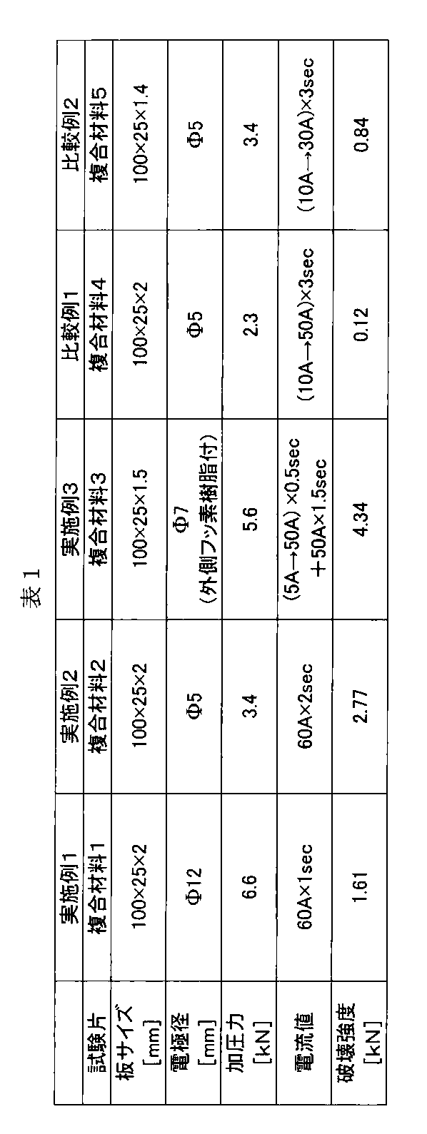
炭素繊維(東邦テナックス(株)製:テナックスSTS40−24KS(繊維径7μm、繊維幅10mm))を20mm幅に開繊しながら、繊維長20mmにカットした。ついで、炭素繊維の供給量を301g/minでテーパー管内に導入し、テーパー管内で空気を炭素繊維に吹き付けて繊維束を部分的に開繊しつつ、テーパー管出口の下部に設置したテーブル上に散布した。
一方、マトリックス樹脂として、平均粒径1mmに粉砕した粉体状PA6(以下ポリアミド)(宇部興産(株)製 1015B)を準備した。これを480g/minでテーパー管内に供給し、炭素繊維と同時に散布することで、平均繊維長20mmの炭素繊維とポリアミドが混合されたマットを得た。得られたマットの臨界単糸数は86であり、炭素繊維束について、マットの繊維全量に対する体積割合は30%、強化繊維束(A)中の平均繊維数(N)は320であった。
このマットを4枚積層して300℃、2MPaでホットプレスして厚さ1.6mmの複合材料を作製した。Eδは1.1、Vfは29.6体積%であった。
この複合材料で板サイズを100mm×25mm×1.5mmとしたものを2枚用意し、重ね合わせて、先端φ12の銅製電極で挟んだ。接合点数は1点とし、加圧力は6.6kN(58.4MPa)とした。加圧状態のまま、直流電源から30Aの電流を1秒間通電させた。その後、冷却完了までの10秒間、電極で加圧を保持した。
(評価)
得られた接合体をインストロン社製万能試験機5587 300kN容量床置型試験機を用い、速度1mm/minで引張せん断試験を実施したところ、破壊強度1.58kNであった。得られた接合体には反りなどの変形は認められなかった。
実施例5
実施例4と同じ複合材料を2枚用意し、重ね合わせて、先端φ5の銅製電極で挟んだ。接合点数は1点とし、加圧力は3.4kN(173MPa)とした。加圧状態のまま、直流電源から30Aの電流を2秒間通電させた。その後、冷却完了までの10秒間、電極で加圧を保持した。
(評価)
得られた接合体をインストロン社製万能試験機5587 300kN容量床置型試験機を用い、速度1mm/minで引張せん断試験を実施したところ、破壊強度2.71kNであった。得られた接合体には反りなどの変形は認められなかった。
実施例6
実施例4と同じ複合材料を2枚用意し、重ね合わせて、内側φ7の銅製電極と外側φ16のフッ素樹脂から構成される加圧補助付電極を用いた。接合点数は1点とし、電極間の加圧力は5.6kN(27.9MPa)とした。加圧状態のまま、直流電源から通電させた。電流値は最初の0.5秒間で2.5Aから25Aまで上昇させ、その後25Aのまま1.5秒間通電させた。通電終了から冷却完了までの10秒間、電極で加圧を保持した。
(評価)
得られた接合体をインストロン社製万能試験機5587 300kN容量床置型試験機を用い、速度1mm/minで引張せん断試験を実施したところ、破壊強度4.25kNであった。得られた接合体には反りなどの変形は認められなかった。
実施例7
実施例4と同じ複合材料を2枚用意し、重ね合せて、φ50、幅10mmの銅製ローラー電極で挟んだ。電極間の加圧力は3.4kNとした。加圧状態のまま、直流電源から30Aの電流を2秒間通電させ、5mm/sの速さで重ね合わせたまま複合材料2枚を移動させた。このとき、ローラー電極の直後にもう1対のローラー加圧機構を設け加圧を行った。このローラーでの加圧力は1.1kNとした。
(評価)
得られた接合体をインストロン社製万能試験機5587 300kN容量床置型試験機を用い、速度1mm/minで引張せん断試験を実施したところ、破壊強度1.55kNであった。得られた接合体には反りなどの変形は認められなかった。
実施例8
炭素繊維(東邦テナックス(株)製:テナックスSTS40−24KS(繊維径7μm、繊維幅10mm))を約25mm幅に開繊しながら、繊維長20mmにカットした。ついで、炭素繊維の供給量を301g/minでテーパー管内に導入し、テーパー管内で空気を炭素繊維に吹き付けて繊維束を部分的に開繊しつつ、テーパー管出口の下部に設置したテーブル上に散布した。
一方、マトリックス樹脂として、平均粒径1mmに粉砕した粉体状PA6(以下ポリアミド)(宇部興産(株)製 1015B)を準備した。これを480g/minでテーパー管内に供給し、炭素繊維と同時に散布することで、平均繊維長20mmの炭素繊維とポリアミドが混合されたマットを得た。得られたマットの臨界単糸数は86であり、炭素繊維束について、マットの繊維全量に対する体積割合は13%、強化繊維束(A)中の平均繊維数(N)は93であった。
このマットを4枚積層して300℃、2MPaでホットプレスして厚さ1.6mmの複合材料を作製した。Eδは1.0、Vfは29.6体積%であった。
上記複合材料を2枚用意し、重ね合わせて、先端φ12の銅製電極で挟んだ。接合点数は1点とし、加圧力は6.6kN(58.4MPa)とした。加圧状態のまま、直流電源から30Aの電流を1秒間通電させた。その後、冷却完了までの10秒間、電極で加圧を保持した。
(評価)
得られた接合体をインストロン社製万能試験機5587 300kN容量床置型試験機を用い、速度1mm/minで引張せん断試験を実施したところ、破壊強度1.47kNであった。得られた接合体には反りなどの変形は認められなかった。
実施例9
炭素繊維(東邦テナックス(株)製:テナックスSTS40−24KS(繊維径7μm、繊維幅10mm))を約15mm幅に開繊しながら、繊維長20mmにカットした。ついで、炭素繊維の供給量を301g/minでテーパー管内に導入し、テーパー管内で空気を炭素繊維に吹き付けて繊維束を部分的に開繊しつつ、テーパー管出口の下部に設置したテーブル上に散布した。
一方、マトリックス樹脂として、平均粒径1mmに粉砕した粉体状PA6(以下ポリアミド)(宇部興産(株)製 1015B)を準備した。これを480g/minでテーパー管内に供給し、炭素繊維と同時に散布することで、平均繊維長20mmの炭素繊維とポリアミドが混合されたマットを得た。得られたマットの臨界単糸数は86であり、炭素繊維束について、マットの繊維全量に対する体積割合は96%、強化繊維束(A)中の平均繊維数(N)は2251であった。
このマットを4枚積層して300℃、2MPaでホットプレスして厚さ1.6mmの複合材料を作製した。Eδは1.1、Vfは29.6体積%であった。
上記複合材料を2枚用意し、重ね合わせて、先端φ12の銅製電極で挟んだ。接合点数は1点とし、加圧力は6.6kN(58.4MPa)とした。加圧状態のまま、直流電源から30Aの電流を1秒間通電させた。その後、冷却完了までの10秒間、電極で加圧を保持した。
(評価)
得られた接合体をインストロン社製万能試験機5587 300kN容量床置型試験機を用い、速度1mm/minで引張せん断試験を実施したところ、破壊強度1.39kNであった。得られた接合体には反りなどの変形は認められなかった。
実施例10
実施例4と同じ複合材料を用意し、ホットプレスで成形した図6に示す2つのハット形状の成形品を接合する。このとき使用する電極はφ7銅製電極と外側φ16のフッ素樹脂から構成される加圧補助付電極を用い、加圧力は5.6kN(27.9MPa)、通電条件は30Aで3秒間とし、通電後5秒間、電極で加圧保持する。接合は50mmの間隔で複数点の接合を行う。
本発明の製造装置によれば、複合材料の接合を低い電流で、反りなどの変形の発生が少なく効率的に行える。
Claims (15)
- (i)熱可塑性樹脂および不連続の炭素繊維を含有し、不連続の炭素繊維がランダムに配置されている複数の複合材料を準備し、
(ii)複数の複合材料を重ね合わせ、
(iii)重ね合わせた部位の少なくとも一部分を一対の電極で挟み、並びに
(iv)電極間に通電しジュール熱で熱可塑性樹脂を溶着させる、
各工程を含む接合体の製造方法。 - 不連続の炭素繊維は、平均繊維長が5~100mmの範囲である請求項1に記載の接合体の製造方法。
- 複合材料は、熱可塑性樹脂100重量部あたり不連続の炭素繊維を10~1000重量部含有する請求項1記載の製造方法。
- 熱可塑性樹脂が、ポリアミド、ポリカーボネート、ポリオキシメチレン、ポリフェニレンスルフィド、ポリフェニレンエーテル、変性ポリフェニレンエーテル、ポリエチレンテレフタレート、ポリブチレンテレフタレート、ポリエチレンナフタレート、ポリエチレン、ポリプロピレン、ポリスチレン、ポリメチルメタクリレート、AS樹脂およびABS樹脂からなる群より選らばれる少なくとも一種である請求項1記載の製造方法。
- 電極で加圧しながら挟む請求項1記載の製造方法。
- 電極およびその周辺を加圧しながら挟む請求項5に記載の製造方法。
- 電極による加圧と、電極周辺の加圧を独立の加圧機構により行う請求項6に記載の製造方法。
- 複合材料をローラー状の電極間に挟み、加圧しながら通電する請求項1記載の製造方法。
- 電流が5~100A、通電時間が1~20秒である請求項1記載の製造方法。
- 通電後、さらに1~30秒の間、電極で挟む請求項1記載の製造方法。
- 熱可塑性樹脂および不連続の炭素繊維を含有し、不連続の炭素繊維がランダムに配置されている複数の複合材料を重ね合わせた接合体を製造する装置であって、
(i)重ね合わせた複数の複合材料の一方の最表層に接する第1の電極、
(ii)重ね合わせた複数の複合材料の他方の最表層に接する第2の電極、
(iii)第1と第2の電極間に通電する電源、
(iv)第1と第2の電極の少なくとも一方に接続された加圧機構、並びに
(v)接合電流と通電時間とを制御する制御装置、
を備え、
複数の複合材料を重ね合わせた部位の少なくとも一部分を第1電極と第2電極で挟み、加圧しながら電極間に通電し、ジュール熱で熱可塑性樹脂を溶着する接合体の製造装置。 - 電極の周辺を加圧する加圧補助機構を有する請求項11に記載の製造装置。
- 電極の加圧機構と、電極の周辺を加圧する加圧補助機構は、各々独立に作用する請求項12に記載の製造装置。
- 第1および第2の電極は、ローラー状で、重ね合わせた複合材料をローラー間に挟み加圧しながら通電を行う請求項11記載の製造装置。
- 熱可塑性樹脂および炭素繊維を含有する複数の複合材料を重ね合わせ、重ね合わせた部位の少なくとも一部分に通電して、熱可塑性樹脂を溶着させ複合材料を接合する方法であって、
複合材料として、熱可塑性樹脂および不連続の炭素繊維を含有し、不連続の炭素繊維がランダムに配置されている複合材料を用いることを特徴とする方法。
Priority Applications (9)
| Application Number | Priority Date | Filing Date | Title |
|---|---|---|---|
| BR112013025935A BR112013025935A2 (pt) | 2011-04-08 | 2012-04-06 | método de fabricar um corpo unido |
| RU2013149793/04A RU2565590C2 (ru) | 2011-04-08 | 2012-04-06 | Способ изготовления соединенного тела |
| CN201280017324.5A CN103561936A (zh) | 2011-04-08 | 2012-04-06 | 接合体的制造方法 |
| US14/009,644 US20140154494A1 (en) | 2011-04-08 | 2012-04-06 | Method of manufacturing a bonded body |
| EP12767549.4A EP2695723A4 (en) | 2011-04-08 | 2012-04-06 | JOINT MANUFACTURING METHOD |
| CA2832652A CA2832652A1 (en) | 2011-04-08 | 2012-04-06 | Method of manufacturing a bonded body |
| MX2013011622A MX2013011622A (es) | 2011-04-08 | 2012-04-06 | Metodo para fabricar un cuerpo unido. |
| JP2013508965A JP5622929B2 (ja) | 2011-04-08 | 2012-04-06 | 接合体の製造方法 |
| KR1020137026310A KR20140038380A (ko) | 2011-04-08 | 2012-04-06 | 접합체의 제조 방법 |
Applications Claiming Priority (2)
| Application Number | Priority Date | Filing Date | Title |
|---|---|---|---|
| JP2011085873 | 2011-04-08 | ||
| JP2011-085873 | 2011-04-08 |
Publications (1)
| Publication Number | Publication Date |
|---|---|
| WO2012137985A1 true WO2012137985A1 (ja) | 2012-10-11 |
Family
ID=46969364
Family Applications (1)
| Application Number | Title | Priority Date | Filing Date |
|---|---|---|---|
| PCT/JP2012/060088 WO2012137985A1 (ja) | 2011-04-08 | 2012-04-06 | 接合体の製造方法 |
Country Status (10)
| Country | Link |
|---|---|
| US (1) | US20140154494A1 (ja) |
| EP (1) | EP2695723A4 (ja) |
| JP (1) | JP5622929B2 (ja) |
| KR (1) | KR20140038380A (ja) |
| CN (1) | CN103561936A (ja) |
| BR (1) | BR112013025935A2 (ja) |
| CA (1) | CA2832652A1 (ja) |
| MX (1) | MX2013011622A (ja) |
| RU (1) | RU2565590C2 (ja) |
| WO (1) | WO2012137985A1 (ja) |
Cited By (5)
| Publication number | Priority date | Publication date | Assignee | Title |
|---|---|---|---|---|
| WO2013099971A1 (ja) * | 2011-12-27 | 2013-07-04 | 帝人株式会社 | 複合材料の接合方法 |
| JP2014177117A (ja) * | 2013-02-14 | 2014-09-25 | Toray Ind Inc | 繊維強化熱可塑性樹脂成形体およびその製造方法 |
| WO2014148643A1 (ja) | 2013-03-22 | 2014-09-25 | オリジン電気株式会社 | 複合材料の接合装置、接合体の製造方法及び接合体 |
| WO2015162998A1 (ja) * | 2014-04-24 | 2015-10-29 | 帝人株式会社 | 繊維強化樹脂接合体、中間体及び締結棒 |
| JPWO2021260813A1 (ja) * | 2020-06-24 | 2021-12-30 |
Families Citing this family (27)
| Publication number | Priority date | Publication date | Assignee | Title |
|---|---|---|---|---|
| US10737447B2 (en) | 2014-04-14 | 2020-08-11 | Short Brothers Plc | Apparatus and method for forming fiber reinforced composite structures |
| US10189113B2 (en) * | 2014-04-24 | 2019-01-29 | GM Global Technology Operations LLC | Resistance spot welding method |
| KR101587998B1 (ko) * | 2014-04-30 | 2016-01-22 | 한양대학교 산학협력단 | 스폿 용접용 압흔 자국 컨트롤 전극 |
| JP6214463B2 (ja) * | 2014-05-15 | 2017-10-18 | Thk株式会社 | ボールジョイント |
| DE102014008623A1 (de) * | 2014-06-17 | 2015-12-17 | Thyssenkrupp Ag | Verfahren zum Widerstandspunktschweißen eines Sandwichmaterials und Vorrichtung hierfür |
| JP6280839B2 (ja) * | 2014-08-22 | 2018-02-14 | 本田技研工業株式会社 | 繊維強化樹脂接合体の製造方法 |
| KR101704415B1 (ko) * | 2015-06-19 | 2017-02-09 | (주)씽크포비엘 | 컴퓨터 기반의 작업 현황 모니터링 시스템 및 이의 작업 근거 데이터 수집 방법 |
| CN107199391B (zh) * | 2016-03-17 | 2019-08-16 | 上海梅山钢铁股份有限公司 | 一种用于铝-钢异种板材焊接的电阻点焊装置及焊接方法 |
| WO2017197428A1 (en) * | 2016-05-18 | 2017-11-23 | Mti Group Pty Ltd | Apparatus and method for welding composite thermoplastic materials |
| FR3063672B1 (fr) | 2017-03-13 | 2022-07-01 | Arkema France | Procede de fabrication de pieces en composite polymere thermoplastique, et objet obtenu par ledit procede |
| KR101948775B1 (ko) * | 2017-05-22 | 2019-04-29 | (주)호원 | 복합소재 접합장치 |
| CN110709128B (zh) * | 2017-06-07 | 2022-02-25 | 花王株式会社 | 微细突起单元的制造方法和微细突起单元 |
| CN109396187B (zh) * | 2017-08-17 | 2021-05-11 | 东莞市富群新材料科技有限公司 | 一种复合金属钢带的制作工艺 |
| KR102184469B1 (ko) * | 2017-09-19 | 2020-11-30 | (주)엘지하우시스 | 섬유 강화 플라스틱 복합시트, 이의 제조방법 및 이의 제조장치 |
| WO2020027869A2 (en) * | 2018-02-07 | 2020-02-06 | ATSP Innovations, Inc. | Method to produce polymer matrix composites |
| DE102018002011A1 (de) | 2018-03-13 | 2019-09-19 | Premium Aerotec Gmbh | Verfahren und Vorrichtung zum thermischen Fügen thermoplastischer Faserverbundbauteile sowie Abdeckung für eine dazu geeignete Druckbeaufschlagungseinrichtung |
| DE102018119991A1 (de) * | 2018-08-16 | 2020-02-20 | Airbus Operations Gmbh | Vorrichtung und Verfahren zum Verbinden thermoplastischer Bauteile durch Widerstandsschweißen, insbesondere für die Herstellung von Luftfahrzeugen |
| JP7099232B2 (ja) * | 2018-09-28 | 2022-07-12 | マツダ株式会社 | 接合装置及び接合方法 |
| JP7127486B2 (ja) * | 2018-10-31 | 2022-08-30 | トヨタ自動車株式会社 | 異材接合方法 |
| KR101982732B1 (ko) * | 2019-01-31 | 2019-05-27 | (주)호원 | 복합소재 접합장치 |
| KR101979614B1 (ko) * | 2019-01-31 | 2019-05-17 | (주)호원 | 복합소재 접합장치 |
| KR101979613B1 (ko) * | 2019-01-31 | 2019-05-17 | (주)호원 | 복합소재 접합장치 |
| WO2020203206A1 (ja) * | 2019-03-29 | 2020-10-08 | リンテック株式会社 | 接合方法及び高周波誘電加熱接着シート |
| JP7479596B2 (ja) * | 2019-03-29 | 2024-05-09 | 三菱瓦斯化学株式会社 | 絶縁性樹脂層付き銅箔、並びに、これを用いた積層体及び積層体の製造方法 |
| DE102019109792A1 (de) * | 2019-04-12 | 2020-10-15 | Deutsches Zentrum für Luft- und Raumfahrt e.V. | Verfahren zum Verschweißen zweier thermoplastischer Fügepartner |
| EP3835034A1 (en) * | 2019-12-13 | 2021-06-16 | SHPP Global Technologies B.V. | Welded fiber-reinforced fittings and methods of making the same |
| CN115103759B (zh) * | 2020-03-03 | 2024-02-13 | 东丽株式会社 | 树脂接合体的制造装置及树脂接合体的制造方法 |
Citations (6)
| Publication number | Priority date | Publication date | Assignee | Title |
|---|---|---|---|---|
| JPS6262733A (ja) | 1985-09-13 | 1987-03-19 | Somar Corp | プラスチツク成形体の接合方法 |
| JPH01195023A (ja) * | 1987-12-10 | 1989-08-04 | Imperial Chem Ind Plc <Ici> | 材料結合方法 |
| JPH03129194A (ja) * | 1989-10-13 | 1991-06-03 | Hitachi Metals Ltd | 融着継手 |
| JPH04504386A (ja) * | 1989-01-10 | 1992-08-06 | コートールズ パブリック リミティド カンパニー | 複合材料の接合方法 |
| JPH1190986A (ja) * | 1997-09-25 | 1999-04-06 | Press Kogyo Co Ltd | 繊維強化樹脂成形体の溶着方法 |
| JP2009073132A (ja) | 2007-09-24 | 2009-04-09 | Toyota Motor Corp | 融着体の製造方法 |
Family Cites Families (13)
| Publication number | Priority date | Publication date | Assignee | Title |
|---|---|---|---|---|
| US2565161A (en) * | 1945-10-06 | 1951-08-21 | Wilmotte | High-frequency dielectric heating |
| US3868291A (en) * | 1973-02-16 | 1975-02-25 | Gottlieb Benz | Welding tool for forming synthetic-resin packages |
| JPS59115592A (ja) * | 1982-12-23 | 1984-07-04 | 佐藤 亮拿 | 電磁遮蔽体の製造方法 |
| US4673450A (en) * | 1985-01-22 | 1987-06-16 | The Boeing Company | Method of welding together graphite fiber reinforced thermoplastic laminates |
| FR2637534B1 (fr) * | 1988-10-11 | 1991-04-12 | Pascal Roger | Procede de fabrication d'une piece en materiau composite par pressage et piece obtenue par ce procede |
| JPH0347735A (ja) * | 1989-07-17 | 1991-02-28 | Kazumasa Moriya | 複合材の接合方法とその装置 |
| JP2719981B2 (ja) * | 1990-11-06 | 1998-02-25 | 第一高周波工業株式会社 | 樹脂の接合方法 |
| US6284089B1 (en) * | 1997-12-23 | 2001-09-04 | The Boeing Company | Thermoplastic seam welds |
| DE102006001833A1 (de) * | 2006-01-13 | 2007-07-19 | Emitec Gesellschaft Für Emissionstechnologie Mbh | Diskontinuierliches Verschweißen von metallischen Fasern |
| WO2007126133A1 (ja) * | 2006-04-27 | 2007-11-08 | Teijin Limited | 炭素繊維複合シート |
| UA19432U (en) * | 2006-06-20 | 2006-12-15 | Zaporizhia Medical Academy Of | Method for diagnosing oxidative stress in patients with larynx carcinoma |
| CN101711230B (zh) * | 2007-06-04 | 2012-10-17 | 东丽株式会社 | 短切纤维束、成型材料、纤维增强塑料以及它们的制造方法 |
| JP5352893B2 (ja) * | 2008-04-14 | 2013-11-27 | 東洋炭素株式会社 | 炭素繊維炭素複合成形体及び炭素繊維強化炭素複合体材料並びにその製造方法 |
-
2012
- 2012-04-06 EP EP12767549.4A patent/EP2695723A4/en not_active Withdrawn
- 2012-04-06 WO PCT/JP2012/060088 patent/WO2012137985A1/ja active Application Filing
- 2012-04-06 KR KR1020137026310A patent/KR20140038380A/ko not_active Application Discontinuation
- 2012-04-06 JP JP2013508965A patent/JP5622929B2/ja not_active Expired - Fee Related
- 2012-04-06 MX MX2013011622A patent/MX2013011622A/es not_active Application Discontinuation
- 2012-04-06 CA CA2832652A patent/CA2832652A1/en not_active Abandoned
- 2012-04-06 US US14/009,644 patent/US20140154494A1/en not_active Abandoned
- 2012-04-06 BR BR112013025935A patent/BR112013025935A2/pt not_active IP Right Cessation
- 2012-04-06 CN CN201280017324.5A patent/CN103561936A/zh active Pending
- 2012-04-06 RU RU2013149793/04A patent/RU2565590C2/ru not_active IP Right Cessation
Patent Citations (6)
| Publication number | Priority date | Publication date | Assignee | Title |
|---|---|---|---|---|
| JPS6262733A (ja) | 1985-09-13 | 1987-03-19 | Somar Corp | プラスチツク成形体の接合方法 |
| JPH01195023A (ja) * | 1987-12-10 | 1989-08-04 | Imperial Chem Ind Plc <Ici> | 材料結合方法 |
| JPH04504386A (ja) * | 1989-01-10 | 1992-08-06 | コートールズ パブリック リミティド カンパニー | 複合材料の接合方法 |
| JPH03129194A (ja) * | 1989-10-13 | 1991-06-03 | Hitachi Metals Ltd | 融着継手 |
| JPH1190986A (ja) * | 1997-09-25 | 1999-04-06 | Press Kogyo Co Ltd | 繊維強化樹脂成形体の溶着方法 |
| JP2009073132A (ja) | 2007-09-24 | 2009-04-09 | Toyota Motor Corp | 融着体の製造方法 |
Non-Patent Citations (1)
| Title |
|---|
| KAZUMASA MORIYA: "bonding by the resistance spot welding of a carbon fiber-reinforced thermoplastic composite material", JOURNAL OF THE JAPAN SOCIETY FOR AERONAUTICAL AND SPACE SCIENCES, vol. 42, April 1994 (1994-04-01), pages 259 - 266 |
Cited By (10)
| Publication number | Priority date | Publication date | Assignee | Title |
|---|---|---|---|---|
| WO2013099971A1 (ja) * | 2011-12-27 | 2013-07-04 | 帝人株式会社 | 複合材料の接合方法 |
| JP2014177117A (ja) * | 2013-02-14 | 2014-09-25 | Toray Ind Inc | 繊維強化熱可塑性樹脂成形体およびその製造方法 |
| WO2014148643A1 (ja) | 2013-03-22 | 2014-09-25 | オリジン電気株式会社 | 複合材料の接合装置、接合体の製造方法及び接合体 |
| JP5827771B2 (ja) * | 2013-03-22 | 2015-12-02 | オリジン電気株式会社 | 複合材料の接合装置、接合体の製造方法 |
| WO2015162998A1 (ja) * | 2014-04-24 | 2015-10-29 | 帝人株式会社 | 繊維強化樹脂接合体、中間体及び締結棒 |
| JP5883545B1 (ja) * | 2014-04-24 | 2016-03-15 | 帝人株式会社 | 繊維強化樹脂接合体、中間体及び締結棒 |
| US9556891B2 (en) | 2014-04-24 | 2017-01-31 | Teijin Limited | Fiber reinforced resin joined body, intermediate body, and fastening rod |
| JPWO2021260813A1 (ja) * | 2020-06-24 | 2021-12-30 | ||
| WO2021260813A1 (ja) * | 2020-06-24 | 2021-12-30 | 三菱重工業株式会社 | 接合方法 |
| JP7331260B2 (ja) | 2020-06-24 | 2023-08-22 | 三菱重工業株式会社 | 接合方法 |
Also Published As
| Publication number | Publication date |
|---|---|
| RU2565590C2 (ru) | 2015-10-20 |
| KR20140038380A (ko) | 2014-03-28 |
| EP2695723A4 (en) | 2014-09-10 |
| CN103561936A (zh) | 2014-02-05 |
| EP2695723A1 (en) | 2014-02-12 |
| BR112013025935A2 (pt) | 2016-12-20 |
| US20140154494A1 (en) | 2014-06-05 |
| JP5622929B2 (ja) | 2014-11-12 |
| JPWO2012137985A1 (ja) | 2014-07-28 |
| RU2013149793A (ru) | 2015-05-20 |
| CA2832652A1 (en) | 2012-10-11 |
| MX2013011622A (es) | 2014-03-27 |
Similar Documents
| Publication | Publication Date | Title |
|---|---|---|
| JP5622929B2 (ja) | 接合体の製造方法 | |
| Xiong et al. | Resistance welding technology of fiber reinforced polymer composites: a review | |
| Villegas et al. | Ultrasonic welding of advanced thermoplastic composites: An investigation on energy‐directing surfaces | |
| WO2013099971A1 (ja) | 複合材料の接合方法 | |
| JP5827771B2 (ja) | 複合材料の接合装置、接合体の製造方法 | |
| Li et al. | Ultrasonic welding of fiber-reinforced thermoplastic composites: A review | |
| JP5833323B2 (ja) | 炭素繊維複合材料の接合部材の製造方法 | |
| JP5770395B2 (ja) | 繊維強化プラスチック接合体及びその製造方法 | |
| WO2013084963A1 (ja) | 接合部材の製造方法 | |
| Choudhury et al. | Analysis of tensile failure load of single-lap green composite specimen welded by high-frequency ultrasonic vibration | |
| CN109910318B (zh) | 一种使用界面原位复合相增强金属/高分子连接强度的方法 | |
| JPWO2015163218A1 (ja) | 繊維強化プラスチック接合体、繊維強化プラスチック接合体の製造方法、および繊維強化成形体 | |
| JP5827505B2 (ja) | 繊維強化熱可塑性樹脂の接合方法 | |
| JP6302606B1 (ja) | 接合体の製造方法 | |
| Worrall et al. | Novel induction heating technique for joining of carbon fibre composites | |
| JP2013129159A (ja) | 接合体の製造方法 | |
| JP6488584B2 (ja) | 炭素繊維強化熱可塑性樹脂成形品と金属の溶着接合体 | |
| JP6508510B2 (ja) | 炭素繊維強化複合材料成形体およびその製造方法、並びに炭素繊維強化複合材料成形体の修復方法 | |
| Totla et al. | Resistance welding analysis of thermoplastic composite structures in aeronautical applications | |
| GB2475886A (en) | Method of welding sheet material | |
| CN116000439A (zh) | 一种搅拌摩擦焊接方法及设备 | |
| JP2009178997A (ja) | 繊維強化樹脂補強鋼板の製造方法及び繊維強化樹脂補強鋼板 | |
| PL244164B1 (pl) | Sposób rezystancyjno-ultradźwiękowego zgrzewania punktowego kompozytów metal-polimer-metal z blachą oraz urządzenie do realizacji tego sposobu | |
| Zhao et al. | Towards high-quality multi-spot-welded joints in thermoplastic composite structures | |
| JP2019055537A (ja) | 金属樹脂接合体およびその製造方法 |
Legal Events
| Date | Code | Title | Description |
|---|---|---|---|
| 121 | Ep: the epo has been informed by wipo that ep was designated in this application |
Ref document number: 12767549 Country of ref document: EP Kind code of ref document: A1 |
|
| ENP | Entry into the national phase |
Ref document number: 2013508965 Country of ref document: JP Kind code of ref document: A |
|
| ENP | Entry into the national phase |
Ref document number: 20137026310 Country of ref document: KR Kind code of ref document: A |
|
| WWE | Wipo information: entry into national phase |
Ref document number: MX/A/2013/011622 Country of ref document: MX |
|
| ENP | Entry into the national phase |
Ref document number: 2832652 Country of ref document: CA |
|
| WWE | Wipo information: entry into national phase |
Ref document number: IDW00201304636 Country of ref document: ID |
|
| NENP | Non-entry into the national phase |
Ref country code: DE |
|
| WWE | Wipo information: entry into national phase |
Ref document number: 2012767549 Country of ref document: EP |
|
| ENP | Entry into the national phase |
Ref document number: 2013149793 Country of ref document: RU Kind code of ref document: A |
|
| REG | Reference to national code |
Ref country code: BR Ref legal event code: B01A Ref document number: 112013025935 Country of ref document: BR |
|
| WWE | Wipo information: entry into national phase |
Ref document number: 14009644 Country of ref document: US |
|
| ENP | Entry into the national phase |
Ref document number: 112013025935 Country of ref document: BR Kind code of ref document: A2 Effective date: 20131008 |