WO2012137904A1 - 袋詰電極の製造装置および製造方法 - Google Patents
袋詰電極の製造装置および製造方法 Download PDFInfo
- Publication number
- WO2012137904A1 WO2012137904A1 PCT/JP2012/059475 JP2012059475W WO2012137904A1 WO 2012137904 A1 WO2012137904 A1 WO 2012137904A1 JP 2012059475 W JP2012059475 W JP 2012059475W WO 2012137904 A1 WO2012137904 A1 WO 2012137904A1
- Authority
- WO
- WIPO (PCT)
- Prior art keywords
- electrode
- separator
- positive electrode
- pair
- separators
- Prior art date
Links
Images


Classifications
-
- H—ELECTRICITY
- H01—ELECTRIC ELEMENTS
- H01M—PROCESSES OR MEANS, e.g. BATTERIES, FOR THE DIRECT CONVERSION OF CHEMICAL ENERGY INTO ELECTRICAL ENERGY
- H01M10/00—Secondary cells; Manufacture thereof
- H01M10/04—Construction or manufacture in general
- H01M10/0404—Machines for assembling batteries
-
- B—PERFORMING OPERATIONS; TRANSPORTING
- B29—WORKING OF PLASTICS; WORKING OF SUBSTANCES IN A PLASTIC STATE IN GENERAL
- B29C—SHAPING OR JOINING OF PLASTICS; SHAPING OF MATERIAL IN A PLASTIC STATE, NOT OTHERWISE PROVIDED FOR; AFTER-TREATMENT OF THE SHAPED PRODUCTS, e.g. REPAIRING
- B29C65/00—Joining or sealing of preformed parts, e.g. welding of plastics materials; Apparatus therefor
- B29C65/02—Joining or sealing of preformed parts, e.g. welding of plastics materials; Apparatus therefor by heating, with or without pressure
- B29C65/18—Joining or sealing of preformed parts, e.g. welding of plastics materials; Apparatus therefor by heating, with or without pressure using heated tools
-
- B—PERFORMING OPERATIONS; TRANSPORTING
- B29—WORKING OF PLASTICS; WORKING OF SUBSTANCES IN A PLASTIC STATE IN GENERAL
- B29C—SHAPING OR JOINING OF PLASTICS; SHAPING OF MATERIAL IN A PLASTIC STATE, NOT OTHERWISE PROVIDED FOR; AFTER-TREATMENT OF THE SHAPED PRODUCTS, e.g. REPAIRING
- B29C65/00—Joining or sealing of preformed parts, e.g. welding of plastics materials; Apparatus therefor
- B29C65/48—Joining or sealing of preformed parts, e.g. welding of plastics materials; Apparatus therefor using adhesives, i.e. using supplementary joining material; solvent bonding
-
- B—PERFORMING OPERATIONS; TRANSPORTING
- B29—WORKING OF PLASTICS; WORKING OF SUBSTANCES IN A PLASTIC STATE IN GENERAL
- B29C—SHAPING OR JOINING OF PLASTICS; SHAPING OF MATERIAL IN A PLASTIC STATE, NOT OTHERWISE PROVIDED FOR; AFTER-TREATMENT OF THE SHAPED PRODUCTS, e.g. REPAIRING
- B29C65/00—Joining or sealing of preformed parts, e.g. welding of plastics materials; Apparatus therefor
- B29C65/56—Joining or sealing of preformed parts, e.g. welding of plastics materials; Apparatus therefor using mechanical means or mechanical connections, e.g. form-fits
-
- B—PERFORMING OPERATIONS; TRANSPORTING
- B29—WORKING OF PLASTICS; WORKING OF SUBSTANCES IN A PLASTIC STATE IN GENERAL
- B29C—SHAPING OR JOINING OF PLASTICS; SHAPING OF MATERIAL IN A PLASTIC STATE, NOT OTHERWISE PROVIDED FOR; AFTER-TREATMENT OF THE SHAPED PRODUCTS, e.g. REPAIRING
- B29C65/00—Joining or sealing of preformed parts, e.g. welding of plastics materials; Apparatus therefor
- B29C65/78—Means for handling the parts to be joined, e.g. for making containers or hollow articles, e.g. means for handling sheets, plates, web-like materials, tubular articles, hollow articles or elements to be joined therewith; Means for discharging the joined articles from the joining apparatus
- B29C65/7802—Positioning the parts to be joined, e.g. aligning, indexing or centring
-
- B—PERFORMING OPERATIONS; TRANSPORTING
- B29—WORKING OF PLASTICS; WORKING OF SUBSTANCES IN A PLASTIC STATE IN GENERAL
- B29C—SHAPING OR JOINING OF PLASTICS; SHAPING OF MATERIAL IN A PLASTIC STATE, NOT OTHERWISE PROVIDED FOR; AFTER-TREATMENT OF THE SHAPED PRODUCTS, e.g. REPAIRING
- B29C65/00—Joining or sealing of preformed parts, e.g. welding of plastics materials; Apparatus therefor
- B29C65/78—Means for handling the parts to be joined, e.g. for making containers or hollow articles, e.g. means for handling sheets, plates, web-like materials, tubular articles, hollow articles or elements to be joined therewith; Means for discharging the joined articles from the joining apparatus
- B29C65/7841—Holding or clamping means for handling purposes
- B29C65/7847—Holding or clamping means for handling purposes using vacuum to hold at least one of the parts to be joined
-
- B—PERFORMING OPERATIONS; TRANSPORTING
- B29—WORKING OF PLASTICS; WORKING OF SUBSTANCES IN A PLASTIC STATE IN GENERAL
- B29C—SHAPING OR JOINING OF PLASTICS; SHAPING OF MATERIAL IN A PLASTIC STATE, NOT OTHERWISE PROVIDED FOR; AFTER-TREATMENT OF THE SHAPED PRODUCTS, e.g. REPAIRING
- B29C65/00—Joining or sealing of preformed parts, e.g. welding of plastics materials; Apparatus therefor
- B29C65/78—Means for handling the parts to be joined, e.g. for making containers or hollow articles, e.g. means for handling sheets, plates, web-like materials, tubular articles, hollow articles or elements to be joined therewith; Means for discharging the joined articles from the joining apparatus
- B29C65/80—Rotatable transfer means for loading or unloading purposes, i.e. turret transfer means
-
- B—PERFORMING OPERATIONS; TRANSPORTING
- B29—WORKING OF PLASTICS; WORKING OF SUBSTANCES IN A PLASTIC STATE IN GENERAL
- B29C—SHAPING OR JOINING OF PLASTICS; SHAPING OF MATERIAL IN A PLASTIC STATE, NOT OTHERWISE PROVIDED FOR; AFTER-TREATMENT OF THE SHAPED PRODUCTS, e.g. REPAIRING
- B29C66/00—General aspects of processes or apparatus for joining preformed parts
- B29C66/01—General aspects dealing with the joint area or with the area to be joined
- B29C66/05—Particular design of joint configurations
- B29C66/10—Particular design of joint configurations particular design of the joint cross-sections
- B29C66/11—Joint cross-sections comprising a single joint-segment, i.e. one of the parts to be joined comprising a single joint-segment in the joint cross-section
- B29C66/112—Single lapped joints
- B29C66/1122—Single lap to lap joints, i.e. overlap joints
-
- B—PERFORMING OPERATIONS; TRANSPORTING
- B29—WORKING OF PLASTICS; WORKING OF SUBSTANCES IN A PLASTIC STATE IN GENERAL
- B29C—SHAPING OR JOINING OF PLASTICS; SHAPING OF MATERIAL IN A PLASTIC STATE, NOT OTHERWISE PROVIDED FOR; AFTER-TREATMENT OF THE SHAPED PRODUCTS, e.g. REPAIRING
- B29C66/00—General aspects of processes or apparatus for joining preformed parts
- B29C66/01—General aspects dealing with the joint area or with the area to be joined
- B29C66/05—Particular design of joint configurations
- B29C66/20—Particular design of joint configurations particular design of the joint lines, e.g. of the weld lines
- B29C66/21—Particular design of joint configurations particular design of the joint lines, e.g. of the weld lines said joint lines being formed by a single dot or dash or by several dots or dashes, i.e. spot joining or spot welding
-
- B—PERFORMING OPERATIONS; TRANSPORTING
- B29—WORKING OF PLASTICS; WORKING OF SUBSTANCES IN A PLASTIC STATE IN GENERAL
- B29C—SHAPING OR JOINING OF PLASTICS; SHAPING OF MATERIAL IN A PLASTIC STATE, NOT OTHERWISE PROVIDED FOR; AFTER-TREATMENT OF THE SHAPED PRODUCTS, e.g. REPAIRING
- B29C66/00—General aspects of processes or apparatus for joining preformed parts
- B29C66/40—General aspects of joining substantially flat articles, e.g. plates, sheets or web-like materials; Making flat seams in tubular or hollow articles; Joining single elements to substantially flat surfaces
- B29C66/41—Joining substantially flat articles ; Making flat seams in tubular or hollow articles
- B29C66/43—Joining a relatively small portion of the surface of said articles
- B29C66/433—Casing-in, i.e. enclosing an element between two sheets by an outlined seam
-
- B—PERFORMING OPERATIONS; TRANSPORTING
- B29—WORKING OF PLASTICS; WORKING OF SUBSTANCES IN A PLASTIC STATE IN GENERAL
- B29C—SHAPING OR JOINING OF PLASTICS; SHAPING OF MATERIAL IN A PLASTIC STATE, NOT OTHERWISE PROVIDED FOR; AFTER-TREATMENT OF THE SHAPED PRODUCTS, e.g. REPAIRING
- B29C66/00—General aspects of processes or apparatus for joining preformed parts
- B29C66/80—General aspects of machine operations or constructions and parts thereof
- B29C66/81—General aspects of the pressing elements, i.e. the elements applying pressure on the parts to be joined in the area to be joined, e.g. the welding jaws or clamps
- B29C66/812—General aspects of the pressing elements, i.e. the elements applying pressure on the parts to be joined in the area to be joined, e.g. the welding jaws or clamps characterised by the composition, by the structure, by the intensive physical properties or by the optical properties of the material constituting the pressing elements, e.g. constituting the welding jaws or clamps
- B29C66/8126—General aspects of the pressing elements, i.e. the elements applying pressure on the parts to be joined in the area to be joined, e.g. the welding jaws or clamps characterised by the composition, by the structure, by the intensive physical properties or by the optical properties of the material constituting the pressing elements, e.g. constituting the welding jaws or clamps characterised by the intensive physical properties or by the optical properties of the material constituting the pressing elements, e.g. constituting the welding jaws or clamps
- B29C66/81266—Optical properties, e.g. transparency, reflectivity
- B29C66/81267—Transparent to electromagnetic radiation, e.g. to visible light
-
- B—PERFORMING OPERATIONS; TRANSPORTING
- B29—WORKING OF PLASTICS; WORKING OF SUBSTANCES IN A PLASTIC STATE IN GENERAL
- B29C—SHAPING OR JOINING OF PLASTICS; SHAPING OF MATERIAL IN A PLASTIC STATE, NOT OTHERWISE PROVIDED FOR; AFTER-TREATMENT OF THE SHAPED PRODUCTS, e.g. REPAIRING
- B29C66/00—General aspects of processes or apparatus for joining preformed parts
- B29C66/80—General aspects of machine operations or constructions and parts thereof
- B29C66/81—General aspects of the pressing elements, i.e. the elements applying pressure on the parts to be joined in the area to be joined, e.g. the welding jaws or clamps
- B29C66/814—General aspects of the pressing elements, i.e. the elements applying pressure on the parts to be joined in the area to be joined, e.g. the welding jaws or clamps characterised by the design of the pressing elements, e.g. of the welding jaws or clamps
- B29C66/8141—General aspects of the pressing elements, i.e. the elements applying pressure on the parts to be joined in the area to be joined, e.g. the welding jaws or clamps characterised by the design of the pressing elements, e.g. of the welding jaws or clamps characterised by the surface geometry of the part of the pressing elements, e.g. welding jaws or clamps, coming into contact with the parts to be joined
- B29C66/81427—General aspects of the pressing elements, i.e. the elements applying pressure on the parts to be joined in the area to be joined, e.g. the welding jaws or clamps characterised by the design of the pressing elements, e.g. of the welding jaws or clamps characterised by the surface geometry of the part of the pressing elements, e.g. welding jaws or clamps, coming into contact with the parts to be joined comprising a single ridge, e.g. for making a weakening line; comprising a single tooth
- B29C66/81429—General aspects of the pressing elements, i.e. the elements applying pressure on the parts to be joined in the area to be joined, e.g. the welding jaws or clamps characterised by the design of the pressing elements, e.g. of the welding jaws or clamps characterised by the surface geometry of the part of the pressing elements, e.g. welding jaws or clamps, coming into contact with the parts to be joined comprising a single ridge, e.g. for making a weakening line; comprising a single tooth comprising a single tooth
-
- B—PERFORMING OPERATIONS; TRANSPORTING
- B29—WORKING OF PLASTICS; WORKING OF SUBSTANCES IN A PLASTIC STATE IN GENERAL
- B29C—SHAPING OR JOINING OF PLASTICS; SHAPING OF MATERIAL IN A PLASTIC STATE, NOT OTHERWISE PROVIDED FOR; AFTER-TREATMENT OF THE SHAPED PRODUCTS, e.g. REPAIRING
- B29C66/00—General aspects of processes or apparatus for joining preformed parts
- B29C66/80—General aspects of machine operations or constructions and parts thereof
- B29C66/83—General aspects of machine operations or constructions and parts thereof characterised by the movement of the joining or pressing tools
- B29C66/834—General aspects of machine operations or constructions and parts thereof characterised by the movement of the joining or pressing tools moving with the parts to be joined
- B29C66/8351—Jaws mounted on rollers, cylinders, drums, bands, belts or chains; Flying jaws
- B29C66/83541—Jaws mounted on rollers, cylinders, drums, bands, belts or chains; Flying jaws flying jaws, e.g. jaws mounted on crank mechanisms or following a hand over hand movement
- B29C66/83543—Jaws mounted on rollers, cylinders, drums, bands, belts or chains; Flying jaws flying jaws, e.g. jaws mounted on crank mechanisms or following a hand over hand movement cooperating flying jaws
-
- B—PERFORMING OPERATIONS; TRANSPORTING
- B29—WORKING OF PLASTICS; WORKING OF SUBSTANCES IN A PLASTIC STATE IN GENERAL
- B29C—SHAPING OR JOINING OF PLASTICS; SHAPING OF MATERIAL IN A PLASTIC STATE, NOT OTHERWISE PROVIDED FOR; AFTER-TREATMENT OF THE SHAPED PRODUCTS, e.g. REPAIRING
- B29C66/00—General aspects of processes or apparatus for joining preformed parts
- B29C66/90—Measuring or controlling the joining process
- B29C66/96—Measuring or controlling the joining process characterised by the method for implementing the controlling of the joining process
- B29C66/967—Measuring or controlling the joining process characterised by the method for implementing the controlling of the joining process involving special data inputs or special data outputs, e.g. for monitoring purposes
- B29C66/9672—Measuring or controlling the joining process characterised by the method for implementing the controlling of the joining process involving special data inputs or special data outputs, e.g. for monitoring purposes involving special data inputs, e.g. involving barcodes, RFID tags
-
- H—ELECTRICITY
- H01—ELECTRIC ELEMENTS
- H01M—PROCESSES OR MEANS, e.g. BATTERIES, FOR THE DIRECT CONVERSION OF CHEMICAL ENERGY INTO ELECTRICAL ENERGY
- H01M10/00—Secondary cells; Manufacture thereof
- H01M10/04—Construction or manufacture in general
- H01M10/0463—Cells or batteries with horizontal or inclined electrodes
-
- H—ELECTRICITY
- H01—ELECTRIC ELEMENTS
- H01M—PROCESSES OR MEANS, e.g. BATTERIES, FOR THE DIRECT CONVERSION OF CHEMICAL ENERGY INTO ELECTRICAL ENERGY
- H01M10/00—Secondary cells; Manufacture thereof
- H01M10/05—Accumulators with non-aqueous electrolyte
- H01M10/052—Li-accumulators
- H01M10/0525—Rocking-chair batteries, i.e. batteries with lithium insertion or intercalation in both electrodes; Lithium-ion batteries
-
- H—ELECTRICITY
- H01—ELECTRIC ELEMENTS
- H01M—PROCESSES OR MEANS, e.g. BATTERIES, FOR THE DIRECT CONVERSION OF CHEMICAL ENERGY INTO ELECTRICAL ENERGY
- H01M10/00—Secondary cells; Manufacture thereof
- H01M10/05—Accumulators with non-aqueous electrolyte
- H01M10/058—Construction or manufacture
-
- H—ELECTRICITY
- H01—ELECTRIC ELEMENTS
- H01M—PROCESSES OR MEANS, e.g. BATTERIES, FOR THE DIRECT CONVERSION OF CHEMICAL ENERGY INTO ELECTRICAL ENERGY
- H01M10/00—Secondary cells; Manufacture thereof
- H01M10/05—Accumulators with non-aqueous electrolyte
- H01M10/058—Construction or manufacture
- H01M10/0585—Construction or manufacture of accumulators having only flat construction elements, i.e. flat positive electrodes, flat negative electrodes and flat separators
-
- H—ELECTRICITY
- H01—ELECTRIC ELEMENTS
- H01M—PROCESSES OR MEANS, e.g. BATTERIES, FOR THE DIRECT CONVERSION OF CHEMICAL ENERGY INTO ELECTRICAL ENERGY
- H01M50/00—Constructional details or processes of manufacture of the non-active parts of electrochemical cells other than fuel cells, e.g. hybrid cells
- H01M50/40—Separators; Membranes; Diaphragms; Spacing elements inside cells
- H01M50/46—Separators, membranes or diaphragms characterised by their combination with electrodes
-
- H—ELECTRICITY
- H01—ELECTRIC ELEMENTS
- H01M—PROCESSES OR MEANS, e.g. BATTERIES, FOR THE DIRECT CONVERSION OF CHEMICAL ENERGY INTO ELECTRICAL ENERGY
- H01M50/00—Constructional details or processes of manufacture of the non-active parts of electrochemical cells other than fuel cells, e.g. hybrid cells
- H01M50/40—Separators; Membranes; Diaphragms; Spacing elements inside cells
- H01M50/463—Separators, membranes or diaphragms characterised by their shape
-
- B—PERFORMING OPERATIONS; TRANSPORTING
- B29—WORKING OF PLASTICS; WORKING OF SUBSTANCES IN A PLASTIC STATE IN GENERAL
- B29L—INDEXING SCHEME ASSOCIATED WITH SUBCLASS B29C, RELATING TO PARTICULAR ARTICLES
- B29L2031/00—Other particular articles
- B29L2031/34—Electrical apparatus, e.g. sparking plugs or parts thereof
- B29L2031/3468—Batteries, accumulators or fuel cells
-
- Y—GENERAL TAGGING OF NEW TECHNOLOGICAL DEVELOPMENTS; GENERAL TAGGING OF CROSS-SECTIONAL TECHNOLOGIES SPANNING OVER SEVERAL SECTIONS OF THE IPC; TECHNICAL SUBJECTS COVERED BY FORMER USPC CROSS-REFERENCE ART COLLECTIONS [XRACs] AND DIGESTS
- Y02—TECHNOLOGIES OR APPLICATIONS FOR MITIGATION OR ADAPTATION AGAINST CLIMATE CHANGE
- Y02E—REDUCTION OF GREENHOUSE GAS [GHG] EMISSIONS, RELATED TO ENERGY GENERATION, TRANSMISSION OR DISTRIBUTION
- Y02E60/00—Enabling technologies; Technologies with a potential or indirect contribution to GHG emissions mitigation
- Y02E60/10—Energy storage using batteries
-
- Y—GENERAL TAGGING OF NEW TECHNOLOGICAL DEVELOPMENTS; GENERAL TAGGING OF CROSS-SECTIONAL TECHNOLOGIES SPANNING OVER SEVERAL SECTIONS OF THE IPC; TECHNICAL SUBJECTS COVERED BY FORMER USPC CROSS-REFERENCE ART COLLECTIONS [XRACs] AND DIGESTS
- Y02—TECHNOLOGIES OR APPLICATIONS FOR MITIGATION OR ADAPTATION AGAINST CLIMATE CHANGE
- Y02P—CLIMATE CHANGE MITIGATION TECHNOLOGIES IN THE PRODUCTION OR PROCESSING OF GOODS
- Y02P70/00—Climate change mitigation technologies in the production process for final industrial or consumer products
- Y02P70/50—Manufacturing or production processes characterised by the final manufactured product
-
- Y—GENERAL TAGGING OF NEW TECHNOLOGICAL DEVELOPMENTS; GENERAL TAGGING OF CROSS-SECTIONAL TECHNOLOGIES SPANNING OVER SEVERAL SECTIONS OF THE IPC; TECHNICAL SUBJECTS COVERED BY FORMER USPC CROSS-REFERENCE ART COLLECTIONS [XRACs] AND DIGESTS
- Y10—TECHNICAL SUBJECTS COVERED BY FORMER USPC
- Y10T—TECHNICAL SUBJECTS COVERED BY FORMER US CLASSIFICATION
- Y10T29/00—Metal working
- Y10T29/49—Method of mechanical manufacture
- Y10T29/49002—Electrical device making
- Y10T29/49108—Electric battery cell making
- Y10T29/49112—Electric battery cell making including laminating of indefinite length material
-
- Y—GENERAL TAGGING OF NEW TECHNOLOGICAL DEVELOPMENTS; GENERAL TAGGING OF CROSS-SECTIONAL TECHNOLOGIES SPANNING OVER SEVERAL SECTIONS OF THE IPC; TECHNICAL SUBJECTS COVERED BY FORMER USPC CROSS-REFERENCE ART COLLECTIONS [XRACs] AND DIGESTS
- Y10—TECHNICAL SUBJECTS COVERED BY FORMER USPC
- Y10T—TECHNICAL SUBJECTS COVERED BY FORMER US CLASSIFICATION
- Y10T29/00—Metal working
- Y10T29/53—Means to assemble or disassemble
- Y10T29/5313—Means to assemble electrical device
- Y10T29/53135—Storage cell or battery
Definitions
- the present invention relates to an apparatus and a method for manufacturing a packaged electrode.
- a stacked battery is formed by forming a positive electrode, a negative electrode and a separator in a sheet, and alternately stacking the positive electrode, the separator, the negative electrode and the separator in this order.
- the positive electrode and the negative electrode may be referred to as an electrode.
- Patent Document 1 first suction-holds the separator on each of the pedestal and the pressure plate while stopping the movement of the pedestal and pressure plate disposed opposite to each other in the vertical direction in the transport direction. .
- the positive electrode is placed on the separator adsorbed on the lower pedestal.
- the upper pressure plate is lowered to place the separator adsorbed on the pressure plate on the positive electrode.
- the edges of the separators overlapping in the periphery of the positive electrode are thermally bonded to produce a packaged positive electrode in which the positive electrode is sandwiched between the bag-like separators.
- the bagging positive electrode is conveyed in a state in which the bagging positive electrode is held between the cradle and the pressure plate, and then the bagned positive electrode is taken out from between the pedestal and the pressure plate, and the bagded positive electrode is alternately laminated with the negative electrode.
- a battery element in which the positive electrode, the separator, the negative electrode, and the separator are alternately stacked in this order is created.
- An object of the present invention is to provide an apparatus and a method for producing a packaged electrode capable of producing a packaged electrode at high speed and shortening the production time of a battery.
- a pair of cylindrical rotating bodies are provided, in which the respective outer circumferential surfaces face each other and are held by rotating the separator on the outer circumferential surface and rotating;
- the electrode is interposed between a pair of separators transported by a pair of cylindrical rotating bodies, and an electrode transporting portion that transports an electrode of a predetermined shape in a tangential direction of the cylindrical rotating bodies toward a space between cylindrical rotating bodies of And a joint portion for joining the separators in a state.
- the pair of separators are simultaneously delivered and laminated from the rotating cylindrical rotating body to both surfaces of the electrode being transported by the electrode transport section, and the pair of separators delivered to both surfaces of the electrode are joined together
- the electrodes are bagged by a separator by joining them by a part.
- the cylindrical rotary body is rotated by holding the separator on each of the outer peripheral surfaces of the pair of cylindrical rotary bodies arranged so as to face each other. And conveying the electrode of a predetermined shape in the tangential direction of the cylindrical rotary body toward the space between the pair of cylindrical rotary bodies. Furthermore, in the manufacturing method, the pair of separators are simultaneously delivered from the rotating cylindrical rotating body and laminated on both surfaces of the electrode being conveyed between the pair of cylindrical rotating bodies, and the electrode And bonding the pair of separators transferred to both sides of the electrode with each other by the separator.
- FIG. 1 is a perspective view showing the appearance of a lithium ion secondary battery.
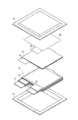
- FIG. 2 is an exploded perspective view of the lithium ion secondary battery.
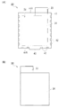
- FIG. 3 is a plan view showing a packaged positive electrode and a negative electrode.
- FIG. 4 is a plan view showing how a negative electrode is superimposed on a packaged positive electrode.
- FIG. 5 is a schematic perspective view showing an apparatus for manufacturing a packaged electrode.
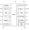
- FIG. 6 is a diagram showing an electrical configuration of a packaged electrode manufacturing apparatus.
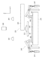
- FIG. 7 is a side view showing an electrode conveyance unit of the packaged electrode manufacturing apparatus.
- FIG. 8 is a front view showing an electrode conveyance unit of the packaged electrode manufacturing apparatus.
- FIG. 9 is a plan view showing an electrode conveyance unit of the packaged electrode manufacturing apparatus.
- FIG. 1 is a perspective view showing the appearance of a lithium ion secondary battery.
- FIG. 2 is an exploded perspective view of the lithium ion secondary battery.
- FIG. 3 is a plan view showing
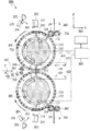
- FIG. 10 is a schematic cross-sectional view showing the rotary conveyance unit of the packaged electrode manufacturing apparatus.
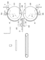
- FIG. 11 is a first explanatory view showing a laminating step by the manufacturing apparatus of the packaged electrode.
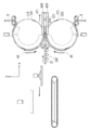
- FIG. 12 is a second explanatory view showing the laminating step by the packaged electrode manufacturing apparatus.
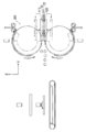
- FIG. 13 is a third explanatory view showing the laminating step by the packaged electrode manufacturing apparatus.
- FIG. 14 is a fourth explanatory view showing the laminating step by the packaged electrode manufacturing apparatus.
- FIG. 15 is a fifth explanatory view showing the laminating step by the packaged electrode manufacturing apparatus.
- FIG. 16 is a sixth explanatory view showing the laminating step by the packaged electrode manufacturing apparatus.
- FIG. 11 is a first explanatory view showing a laminating step by the manufacturing apparatus of the packaged electrode.
- FIG. 12 is a second explanatory view showing the laminating step by the packaged electrode manufacturing apparatus.
- FIG. 13 is a third explanatory view showing
- FIG. 17 is a seventh explanatory view showing the laminating step by the packaged electrode manufacturing apparatus.
- FIG. 18 is an eighth explanatory view showing a laminating step by the packaged electrode manufacturing apparatus.
- FIG. 19 is a chart showing the operation of the rotary conveyance unit.
- FIG. 20 is a schematic cross-sectional view showing another example of a packaged electrode manufacturing apparatus.
- FIG. 21 is a schematic cross-sectional view showing still another example of a packaged electrode manufacturing apparatus.
- the present invention relates to an apparatus and a method for manufacturing a packaged electrode for assembling a power generation element of a battery, which is applied to a part of a manufacturing process of the battery.
- FIG. 1 is a perspective view showing the appearance of a lithium ion secondary battery
- FIG. 2 is an exploded perspective view of the lithium ion secondary battery
- FIG. 3 is a plan view of a packaged positive electrode and a negative electrode.
- the lithium ion secondary battery 10 has a flat rectangular shape, and the positive electrode lead 11 and the negative electrode lead 12 are derived from the same end of the package 13.
- a power generation element (battery element) 15 in which a charge / discharge reaction proceeds is accommodated.
- the power generation element 15 is formed by alternately stacking a packaged positive electrode 20 and a negative electrode 30.
- the rectangular positive electrode 22 is sandwiched between the rectangular separators 40 in the packaged positive electrode 20.
- the positive electrode 22 has a positive electrode active material layer formed on both sides of a very thin sheet-like positive electrode current collector (current collector foil).
- the two separators 40 are bonded to each other at the end portions by a bonding portion 42 and formed in a bag shape.
- the positive electrode tab 23 of the positive electrode 22 is drawn out from the side 44A formed linearly, and an engagement portion 43 partially protruding is formed on the side 44B opposite to the side 44A.
- the engagement portion 43 plays a role of fixing the power generation element 15 to the exterior material 13 by engaging the exterior material 13 inside the exterior material 13.
- the positive electrode 22 has a positive electrode active material layer 24 formed on a portion other than the positive electrode tab 23.
- the negative electrode 30 is formed in a rectangular shape, and a negative electrode active material layer 34 is formed on both sides of a very thin sheet-like negative electrode current collector (current collecting foil).
- a negative electrode active material layer 34 is formed in a portion other than the negative electrode tab 33.
- the negative electrode active material layer 34 is formed to be larger than the positive electrode active material layer 24 of the positive electrode 22.
- the method of manufacturing a lithium ion secondary battery by alternately stacking the packaged positive electrodes 20 and the negative electrodes 30 is a general method of manufacturing a lithium secondary battery, and thus detailed description will be omitted.
- the manufacturing apparatus includes a positive electrode cutting unit 100 for cutting out the positive electrode 22 from the sheet material D for the positive electrode, and an electrode transfer unit 200 for transferring the cut out positive electrode 22. Furthermore, the laminating apparatus generally controls the whole of the apparatus, the rotary conveyance unit 300 provided on the downstream side in the conveyance direction of the electrode conveyance unit 200, the welds 400 (joined parts) provided on both sides of the rotation conveyance unit 300, And a control device 500 (synchronization device) to control.
- the direction in which the positive electrode 22 is transported is described as the transport direction X, the direction perpendicular to the surface of the positive electrode 22 as the vertical direction Z, the vertical direction Z, and the direction orthogonal to the transport direction X as the width direction Y.
- the positive electrode cutting part 100 cuts out the positive electrode 22 (sheet member) having a predetermined shape by cutting the sheet material D for the positive electrode wound in a roll shape into a predetermined shape by punching or the like.
- the positive electrode 22 cut out here has a rectangular shape and has a positive electrode tab 23.
- the electrode transfer unit 200 includes a conveyor 210 and a suction transfer unit 220, as shown in FIGS.
- the conveyor 210 conveys the positive electrode 22 cut out by the positive electrode cutting unit 100.
- the adsorption conveyance unit 220 adsorbs the positive electrode 22 on the conveyor 210 and conveys it to the rotary conveyance unit 300 (separator conveyance unit).
- Above the conveyor 210 an imaging camera 230 (position detection unit) and an illumination 231 are provided.
- the conveyor 210 includes an endless suction belt 211 having air permeability, and two rotation shafts 212 which are arranged side by side in the transport direction and rotatably hold the suction belt 211. Furthermore, the conveyor 210 is provided with a negative pressure generating unit 213 disposed inside the suction belt 211.
- a plurality of air suction holes 214 are formed in the suction belt 211. Then, by sucking the air by the negative pressure generating part 213 through the air suction hole 214, the thin positive electrode 22 which is difficult to convey can be held on the flat installation surface 215 (reference surface) on the conveyor 210 and can be conveyed. It has become.
- the installation surface 215 of the suction belt 211 has a color tone that makes it easy to recognize the boundary with the positive electrode 22 by the imaging camera 230, and the present embodiment is white.
- the conveyor 210 is applied as what is provided with the flat installation surface 215 which can install the positive electrode 22 in a substantially horizontal state.
- the flat installation surface 215 which can install the positive electrode 22 in a substantially horizontal state.
- other devices may be used provided they have a flat mounting surface.
- the pressing unit 240 includes a clamper 242 which approaches or separates from the installation surface 215 (reference surface) on the suction belt 211 by an actuator 241 controlled by the control device 500.
- the clamper 242 corrects the distortion of the positive electrode 22 by pressing the positive electrode 22 against the installation surface 215.
- the positive electrode 22 cut out from the sheet material D wound in a roll shape has a curl and tends to curl.
- the positive electrode 22, the negative electrode 30, and the separator 40 are very thin foil-like materials, and in particular, they are very easily deformed in a large battery such as an automobile battery.
- the suction belt 211 sucks and holds the member in contact with the installation surface 215, the suction belt 211 does not usually have a suction force enough to attract a part away from the installation surface 215. Therefore, the positive electrode 22 is pressed against the mounting surface 215 by the clamper 242 to correct the deformation of the positive electrode 22.
- the position of the positive electrode 22 can be grasped with high accuracy by the imaging camera 230, and the suction position by the suction conveyance unit 220 can also be set with high accuracy. As a result, the processing accuracy in the subsequent steps is improved.
- the clamper 242 is formed so as to be able to press long portions along the two side edges H2 and H4 (edges) along the transport direction of the positive electrode 22 on the suction belt 211.
- the suction position of the positive electrode 22 by the suction conveyance unit 220 can be secured between the clampers 242.
- the clamper 242 presses the inner side of the edges of the four sides H1 to H4, that is, the center side of the cathode 22 so that the four sides H1 to H4 (edges) of the cathode 22 can be imaged by the imaging camera 230.
- the clamper 242 is formed of a transparent member so that the pressed positive electrode 22 can be captured through the clamper 242.
- a transparent member acrylic resin, glass, etc. are applicable, for example.
- the material of the clamper 242 is not particularly limited, and can be appropriately set according to the frequency of the illumination 231 and the imaging characteristics of the imaging camera 230.
- the adsorption conveyance unit 220 is provided with a movable apparatus main body 221 connected to a drive device (not shown) and a lower part of the apparatus main body 221 and is connected to a negative pressure supply source (not shown) so as to have an adsorption force.
- the suction head 222 is provided.
- the suction head 222 is three-dimensionally movable in the vertical direction Z, the transport direction X, and the width direction Y according to the operation of the drive device, and is further rotatable along a horizontal surface.
- the imaging camera 230 provided above the conveyor 210 presses and holds the positive electrode 22 conveyed by the conveyor 210 by the clamper 242, and then images under the light emitted by the illumination 231.
- the imaging camera 230 transmits, to the control device 500, a signal based on the image of the positive electrode 22 captured when the positive electrode 22 is conveyed to a predetermined position and stopped.
- the control device 500 that has received the predetermined signal calculates positional information that is the position and the state of the positive electrode 22 from the signal, and controls the movement of the drive device of the suction conveyance unit 220 based on the result of the calculated positional information. Then, the suction conveyance unit 220 corrects the position and attitude of the positive electrode 22 appropriately, and conveys it to a gap 340 (see FIG. 5) of the rotation conveyance unit 300 described later.
- control device 500 stops the conveyor 210 at a predetermined position, and from the image captured by the imaging camera 230, the edges of the side areas E1 to E4 corresponding to the four sides of the positive electrode 22 shown in FIG. To detect. The edge can be detected from the difference in color tone between the suction belt 211 and the positive electrode 22.
- the control device 500 calculates the approximate straight lines L1 to L4 of the four sides from the detection result using the least squares method or the like.
- control device 500 calculates corner portions K1 to K4 of the four corners which are the intersections of approximate straight lines L1 to L4 of four sides, calculates an average value of four corner portions K1 to K4, and calculates this as the electrode center Let it be the coordinates of point O.
- the coordinates of the electrode center point O are represented by coordinates in the transport direction X and the width direction Y.
- the control device 500 calculates the inclination angle ⁇ of the positive electrode 22 in the horizontal plane (reference plane) from the average value of one or both of the approximate straight lines L2 and L4 of the two side H2 and H4 along the transport direction of the positive electrode 22. Do. Thereafter, the control device 500 calculates the correction amount of the position and the inclination with respect to the normal position of the positive electrode 22 in the horizontal plane from the coordinate of the electrode center point O and the inclination angle ⁇ . Then, the control device 500 controls the drive device of the suction conveyance unit 220 (position correction unit) so as to correct the correction amount. Further, the suction transport unit 220 transports the sheet to the gap 340 of the rotary transport unit 300 while correcting the position of the positive electrode 22.
- the position and state of the positive electrode 22 are recognized by the imaging camera 230.
- other sensors may be used, and the position of the positive electrode 22 can also be recognized by, for example, a contact sensor that detects the tip of the positive electrode 22.
- the positive electrode 22 is conveyed to a predetermined position of the conveyor 210, and the side of the positive electrode 22 is pressed by the clamper 242 to correct the shape of the positive electrode 22.
- the positive electrode 22 is adsorbed and held.
- the suction conveyance unit 220 ascends while maintaining the substantially horizontal state of the positive electrode 22.
- the suction conveyance unit 220 appropriately corrects the position and the attitude of the positive electrode 22 according to the calculated correction amount, and conveys it to the gap 340 of the rotation conveyance unit 300.
- an introduction support portion 250 is provided in the vicinity of the gap 340 of the rotary conveyance unit 300 so as to sandwich the upper and lower sides of the gap 340 and assists the introduction of the positive electrode 22 into the rotary conveyance unit 300.
- the introduction support portion 250 includes a plurality of roller groups, supports the positive electrode 22 conveyed by the suction conveyance portion 220, and feeds the positive electrode 22 into the gap 340 of the rotational conveyance portion 300.
- the introduction support portion 250 includes an upper introduction support portion 251 formed of one roller and a lower introduction support portion 252 formed of a plurality of rollers.
- the upper introduction support portion 251 is movable in the vertical direction Z, and is lowered from the “opened state” which has been moved upward, and the positive electrode 22 is lowered between the lower introduction support portion 252 and the most downstream roller in the transport direction. Can be "closed” to hold the Furthermore, the upper introduction support portion 251 can send out the held positive electrode 22 to the gap 340 by driving to rotate.
- the lower introduction support portion 252 rises from the "opened state” in which the upstream roller in the transport direction descends obliquely, and when the positive electrode 22 is delivered from the suction transport portion 220, becomes substantially horizontal and "closed state” It becomes “. Thereby, as shown in FIG. 14, the lower introduction support portion 252 transportably supports the positive electrode 22.
- the roller on the most downstream side in the transport direction paired with the roller of the upper introduction support portion 251 can be driven to rotate. Therefore, by rotating the roller on the most downstream side in a state in which the positive electrode 22 is held between the upper introduction support portion 251, the held positive electrode 22 can be sent out to the gap 340.
- the upper introduction support unit 251 is lowered to hold the tip of the positive electrode 22 between the lower introduction support unit 252 and the lower introduction support unit 252. Further, the roller of the lower introduction support portion 252 is raised to be substantially horizontal, and the lower surface of the positive electrode 22 is supported. Thereafter, the positive electrode 22 is released from the suction head 222 of the suction conveyance unit 220, and the positive electrode 22 is sequentially fed into the gap 340 of the rotation conveyance unit 300 by the rotation of the introduction support unit 250.
- the rotary conveyance unit 300 (separator conveyance unit) is to laminate the positive electrode 22 conveyed by the suction conveyance unit 220 while cutting out the separator 40 from the sheet-like separator material S.
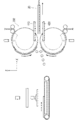
- the rotary conveyance unit 300 includes a pair of upper and lower stacking drums 310 (cylindrical rotating bodies) and stacking drums 320 (cylindrical rotating bodies) formed in a cylindrical shape.
- the rotation axis of the pair of upper and lower stacking drums 310 and 320 is orthogonal to the conveyance direction X. Furthermore, the stacking drums 310 and 320 are disposed parallel to each other such that the outer circumferential surfaces 311 face each other with a predetermined gap 340 therebetween, and have a symmetrical structure with respect to the horizontal plane.
- an adsorption portion capable of adsorbing the separator 40 is formed on the outer peripheral surface 311 of each of the stacking drums 310 and 320. Furthermore, inside the stacking drums 310 and 320, an inner structure portion 330 provided non-rotatably is provided inside the stacking drums 310 and 320. The width (length in the rotation axis direction) of the stacking drums 310 and 320 is such that both edges of the separator material S protrude from both ends of the stacking drums 310 and 320.
- the upper and lower stacking drums 310 and 320 are disposed with a gap 340 therebetween. Then, in the gap 340, the stacking drums 310 and 320 are configured to rotate toward the downstream side in the transport direction X. That is, the stacking drum 310 positioned on the upper side transports the separator 40 adsorbed to the outer peripheral surface 311 to the gap 340 by rotating counterclockwise on the paper surface of FIG. 10. The stacking drum 320 located on the lower side conveys the separator 40 adsorbed on the outer peripheral surface 311 to the gap 340 by rotating clockwise on the paper surface of FIG. 10. The upper and lower stacking drums 310 and 320 are driven by a drive motor (not shown) whose rotation is controlled by the control device 500.
- a drive motor not shown
- innumerable vent holes 312 are formed in the outer peripheral surface 311. Furthermore, on the outer peripheral surface 311, a recessed portion 313 (receiving portion) to which a separator cutter 351 (cutting blade) provided in a cutting portion 350 described later can enter is formed in a part of the circumferential direction.
- the concave portions 313 are formed at two positions every 180 degrees of the stacking drums 310 and 320. The concave portions 313 are provided at two places in the circumferential direction because two separators 40 are cut out each time the stacking drums 310 and 320 make one rotation. However, the number of concave portions 313 in the circumferential direction can be changed according to the number of separators 40 cut out during one rotation of the stacking drums 310 and 320.
- a feed roller portion 360 (lock mechanism) for feeding or restraining the sheet-like separator material S is provided in the vicinity of the outer peripheral surface 311 around the respective stacking drums 310 and 320. Furthermore, the cutting part 350 which cut
- a small-sized delivery roller portion 360 formed in a cylindrical shape is provided obliquely above and obliquely below on the downstream side in the conveyance direction of the rotary conveyance unit 300.
- a pair of delivery rollers 361 and 362 are provided obliquely upward and obliquely downward on the downstream side in the conveyance direction of the rotary conveyance unit 300.
- the delivery rollers 361 and 362 are formed in a cylindrical shape, and are disposed with a predetermined gap.
- the delivery roller portion 360 sandwiches one continuous separator material S conveyed from a separator roll (not shown) in a gap. Then, when the delivery roller unit 360 rotates, the separator material S is delivered to the rotary conveyance unit 300, and by stopping the delivery, the delivery is stopped and the separator material S is restrained.
- the delivery rollers 361 and 362 are controlled by the control device 500 to deliver the separator material S to the rotary conveyance unit 300 at a predetermined timing.
- the cutting unit 350 includes separator cutters 351 above and below the rotary conveyance unit 300.
- the separator cutter 351 is a heat cutter which melts the separator material S adsorbed on the outer peripheral surface 311 of the stacking drums 310 and 320 and cuts it into a predetermined shape. Specifically, first, the separator 40 is adsorbed and conveyed by the outer peripheral surface 311 of the stacking drums 310 and 320. At this time, when the recessed portion 313 of the stacking drum 310, 320 moves to a position facing the separator cutter 351, the separator cutter 351 moves so as to enter the recessed portion 313 of the stacked drum 310, 320 in response to a command from the control device 500. .
- the separator cutter 351 melts the separator 40 and cuts the separator 40 into a predetermined shape as shown in FIG. 3 (A).
- the rear end of the separator 40 to be cut out first is the side 44B on which the engaging portion 43 is formed, and the front end of the separator 40 to be cut out next is the linear side 44A.
- a surplus cut piece S ' is generated.
- the cut piece adsorption unit 370 includes a cutter adsorption head 371 that exerts an adsorption force. Then, at a timing when the separator cutter 351 cuts the separator material S and then moves out of the recess 313 and retreats, the cutter suction head 371 moves so as to approach the cut portion. Thereafter, the suction head 371 for the cutter sucks and holds the surplus cut piece S ′ of the separator 40 cut out by the separator cutter 351. Then, the suction head 371 for the cutter is separated from the outer peripheral surface 311 of the stacking drum 310, 320 while the cut-off piece S 'is held by suction.
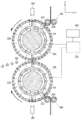
- an inner structure portion 330 is provided inside each of the stacking drums 310 and 320.
- the inner structure portion 330 includes a first negative pressure chamber 331 capable of adjusting the strength of negative pressure according to the process when the device is operating, and a second negative pressure chamber 332 where the negative pressure is kept substantially constant when the device is operating. And are formed non-rotationally.
- the first negative pressure chamber 331 and the second negative pressure chamber 332 are connected to a negative pressure supply device 333 provided with a pressure control valve, and the control device 500 controls the negative pressure supply device 333 to adjust the internal pressure It is possible.
- the first negative pressure chamber 331 and the second negative pressure chamber 332 are isolated from the outside by the inner circumferential surfaces of the stacking drums 310 and 320. Therefore, an area of negative pressure is generated non-rotationally on the outer peripheral surface 311 of the stacking drums 310 and 320 via the vent holes 312 formed in the stacking drums 310 and 320. This area does not rotate even if the stacking drums 310 and 320 rotate.
- the first negative pressure chamber 331 is formed in a range from a position corresponding to the delivery roller portion 360 to a position corresponding to the separator cutter 351 in the rotational direction of the stacking drums 310 and 320.
- the second negative pressure chamber 332 is formed in a range of approximately 180 degrees from the position corresponding to the separator cutter 351 to the position corresponding to the gap 340 in the rotational direction of the stacking drums 310 and 320.
- a slip region A1 (adsorption force adjustment region) where negative pressure is adjusted and changed at a position corresponding to the first negative pressure chamber 331. It is formed. Further, on the outer peripheral surface 311, an adsorption area A2 is formed in which the negative pressure is substantially constant at a position corresponding to the second negative pressure chamber 332 and the separator material S or the cut out separator 40 is adsorbed and held.
- the suction area A2 has a strong suction force, and can hold the separator material S or the cut out separator 40 by the suction force, and can rotate them along the rotation of the stacking drums 310 and 320.
- the slippage area A1 can also be set to a suction force similar to that of the suction area A2, and the separator 40 can be rotated. Furthermore, while the sliding area A1 holds the separator material S not to be separated from the outer peripheral surface 311 by reducing the suction force, the separator material S does not rotate when the stacking drums 310 and 320 rotate. It can slide on the outer circumferential surface 311.
- the range from the position corresponding to the gap 340 of the inner structural portion 330 to the position corresponding to the delivery roller portion 360 in the rotational direction of the stacking drums 310 and 320 is the first negative pressure chamber 331 and the second negative pressure chamber. None of the pressure chambers 332 are provided. Therefore, a non-adsorption area A3 which does not adsorb the separator 40 without generating a negative pressure is formed non-rotatably at a portion corresponding to this range of the outer peripheral surface 311.
- the rotary conveyance unit 300 sucks and conveys the separator 40 while cutting it out with the stacking drums 310 and 320. Furthermore, the rotary conveyance unit 300 synchronizes the speed of rotation of the stacking drums 310 and 320 with the speed of conveyance of the positive electrode 22 by the electrode conveyance unit 200, while separating the separators 40 on both sides of the positive electrode 22 from the downstream side in the conveyance direction X. Stack sequentially. At this time, as shown in FIG. 10, the positive electrode 22 is introduced by the suction conveyance unit 220 in the tangential direction T of the cylindrical stacking drums 310 and 320.
- the welding part 400 welds separators 40 laminated
- the upper and lower welding machines 410 and 420 are provided with a plurality of protrusions 411 and 421 along the transport direction X on the opposing surfaces. Then, welding is possible by heating while pressing the separators 40 with each other by the opposing projections 411 and 421.
- the welding machines 410 and 420 can move in the transport direction X and in the vertical direction Z. That is, the welding machines 410 and 420 move close to each other in the transport direction X at the same speed as the separator 40 so as to be synchronized with the separator 40 and the positive electrode 22 transported to the gap 340 and stacked. Then, the stacked separators 40 are joined together by the opposing protrusions 411 and 421 to form a joined portion 42. Thereafter, when the positive electrode 22 packaged in a bag shape by the separator 40 is transported to a predetermined position, the welding devices 410 and 420 are separated and moved to the upstream side in the transport direction.
- the welding machines 410 and 420 move again at the same speed in the transport direction X at the same speed as the separator 40 and make them approach each other, thereby welding the other bonding site 42. After all the bonding sites 42 are bonded, the welding machines 410 and 420 are separated from each other, and the manufactured packaged positive electrode 20 is released.
- separators 40 it is not limited to the above-mentioned structure. That is, for example, the separators 40 may be welded while being heated between a pair of rotating heating rollers, may be pressure-bonded only by pressure without heating, or may be bonded using an adhesive. .
- the control device 500 cuts the positive electrode cutting unit 100, the imaging camera 230, the pressing unit 240, the conveyor 210, the suction conveyance unit 220, the introduction support unit 250, the delivery roller unit 360, the stacking drums 310 and 320, and The unit 350, the cut piece adsorbing unit 370, the negative pressure supply device 333 and the welding unit 400 are integrated and integrally controlled. Then, the control device 500 can operate the parts shown in FIG. 6 in synchronization. Control device 500 can also perform overall control including other devices for producing a battery.
- the sheet material D for positive electrode wound in a roll shape is cut at the positive electrode cutting portion 100 to form the positive electrode 22.
- the cut-out positive electrode 22 is placed on the installation surface 215 of the conveyor 210 by a suction pad, a conveyor, or the like (not shown).
- the delivery roller portion 360 sandwiches and restrains one continuous separator material S sent from the separator roll in a gap. Therefore, as shown in FIG. 11, the tip of the separator material S is located at the top or bottom of the rotary conveyance unit 300.
- the negative pressure of the first negative pressure chamber 331 is set low, and the separator drums 310 and 320 rotate while sliding on the inner surface of the separator material S without the separator material S being pulled out in the sliding region A1 of the outer peripheral surface 311. doing. Note that, in the present embodiment, since the two separators 40 are cut out by one rotation of the stacking drums 310 and 320, as shown by the two-dot chain line in FIG. , 320 and is transported by suction.
- the conveyor 210 on which the positive electrodes 22 are placed is vertically aligned with the positive electrodes 22 on the installation surface 215 of the suction belt 211 in the transport direction X (the tabs are on the upstream side in the transport direction X) as shown in FIG. Transport to the line).
- the positive electrodes 22 may be conveyed laterally (in a row in which the tabs are positioned in the width direction Y).
- the suction belt 211 moves to a predetermined position, the movement is stopped while the positive electrode 22 is adsorbed. Then, as shown in FIG.
- the pressing portion 240 operates to press the long portions along the two side edges H2 and H4 of the positive electrode 22 by the clamper 242 (see FIGS. 8 and 9). Thereby, deformation such as rounding of the positive electrode 22 is corrected. Then, the portion of the positive electrode 22 floating from the suction belt 211 comes close to the suction belt 211, so that the suction belt 211 sucks and the positive electrode 22 adheres densely on the installation surface 215.
- the imaging camera 230 images the four sides H1 to H4 of the positive electrode 22, and transmits a predetermined signal to the control device 500.
- the control device 500 calculates the coordinates of the electrode center point O and the inclination angle ⁇ from the received signal by the method described above, and calculates the correction amount of the position and inclination of the positive electrode 22 with respect to the normal position.
- the clamper 242 presses the inner side (the center side of the positive electrode 22) than the edge of the four sides H1 to H4 of the positive electrode 22 at the time of imaging, the imaging camera 230 ensures the four sides H1 to H4. It can be imaged.
- the clamper 242 is formed of a transparent material, the positive electrode 22 can be imaged through the clamper 242 even if the clamper 242 is included in the imaging range.
- the suction head 222 of the suction conveyance unit 220 located above the suction belt 211 is lowered to press the suction head 222 against the upper surface of the positive electrode 22.
- the positive electrode 22 is adsorbed by the adsorption head 222.
- the positive electrode 22 is also attracted to the suction belt 211.
- the positive electrode 22 can be pulled away from the suction belt 211 by the suction head 222 by setting the suction force of the suction head 222 higher than that of the suction belt 211 or temporarily stopping the suction by the suction belt 211.
- the stacking drums 310 and 320 rotate, and the recessed portion 313 moves toward the position corresponding to the separator cutter 351.
- the controller 500 increases the negative pressure of the first negative pressure chamber 331 to strengthen the suction force of the sliding area A1.
- the delivery roller portion 360 is rotated to sequentially deliver the sheet S while holding the separator material S between the pair of delivery rollers 361 and 362. Thereby, the supply of the separator material S is started to the stacking drums 310 and 320 (see T1 in FIG. 19).
- the separator material S is adsorbed to the outer peripheral surface 311 of the stacking drums 310 and 320 in the sliding area A1 and the adsorption area A2 where the negative pressure is increased, and the separator materials S are sequentially drawn out as the stacking drums 310 and 320 rotate.
- the predetermined angle ⁇ is an angle corresponding to the length of one separator 40 to be cut out.
- the suction conveyance unit 220 ascends while maintaining the positive electrode 22 in a substantially horizontal state, moves in the conveyance direction X, and conveys it to the gap 340 of the rotary conveyance unit 300.
- the drive device is controlled by the control device 500 to correct the position and posture of the positive electrode 22 in the suction conveyance unit 220.
- the suction conveyance unit 220 corrects the position and posture of the positive electrode 22 between the suction of the positive electrode 22 and the delivery thereof to the rotary conveyance unit 300. Thereby, the position of the positive electrode 22 is always maintained with high accuracy, and the accuracy of lamination in the later process is improved.
- the positive electrode 22 conveyed by the suction conveyance unit 220 reaches the “open state” introduction support unit 250 provided in front of the gap 340 of the rotary conveyance unit 300.
- the introduction support portion 250 lowers the upper introduction support portion 251 to sandwich the tip of the positive electrode 22 with the lower introduction support portion 252.
- the introduction support portion 250 raises the roller of the lower introduction support portion 252 to be in a substantially horizontal state and is in a “closed state”, and supports the lower surface of the positive electrode 22.
- the positive electrode 22 is released from the suction head 222 of the suction conveyance unit 220, and the positive electrode 22 is sequentially fed into the gap 340 of the rotation conveyance unit 300 by the rotation of the introduction support unit 250.
- the rotation conveyance unit 300 when the stacking drums 310 and 320 rotate by the angle ⁇ from the start of rotation, the rotation of the stacking drums 310 and 320 is stopped (see T2 in FIG. 19). At this time, the separator material S is drawn onto the stacking drums 310 and 320 by an angle ⁇ corresponding to one separator 40. Furthermore, the recess 313 is positioned to face the separator cutter 351 of the cutting portion 350. Then, the separator cutter 351 is pressed against the separator material S according to a command from the control device 500, and the separator material S is cut into a predetermined shape to cut out the separator 40. Since the cut-out separator 40 is located in the suction area A2 of the stacking drums 310 and 320 shown in FIG. 11, the separator 40 is held by suction on the stacking drums 310 and 320.
- the separator cutter 351 gets out of the recess 313 and retreats.
- the suction head 371 for the cutter comes close to the excess cut piece S ′ according to a command of the control device 500 and sucks.
- the suction of the suction head 371 for the cutter is stopped and the cut-off piece S 'is released, and the cut-off piece S' is sucked and recovered by the suction port 372 shown in FIG.
- the positive electrode 22 is sequentially fed into the gap 340 of the stacking drums 310 and 320 by the rotation of the introduction support unit 250. Furthermore, the stacking drums 310 and 320 are rotated again (see T4 in FIG. 19), and the cut-out separator 40 is rotated while being sucked and is conveyed to the gap 340.
- the negative pressure of the first negative pressure chamber 331 is reduced by the control device 500 to weaken the adsorption force of the sliding area A1, and the separator material is made by the delivery roller portion 360.
- S be in a constrained state (see FIG. 18).
- the stacking drums 310 and 320 rotate while sliding on the inner surface of the separator material S without the separator 40 being pulled out in the sliding region A1 of the outer peripheral surface 311.
- the control device 500 controls the transport position (the timing of transport) and the transport speed in the rotary transport unit 300 and the suction transport unit 220 so that the separator 40 and the positive electrode 22 overlap at a preset proper position.
- the pair of welding machines 410 and 420 move in the transport direction X while being close to each other, and only the leading ends of both edges of the separator 40 are held and held. Then, while moving the separator 40 and the positive electrode 22 in the transport direction X, welding is performed by the protrusions 411 and 421 (see T5 in FIG. 19). The separator 40 reaches the non-sucking area A3 of the stacking drums 310 and 320 when the gap 340 is passed.
- the separator 40 is separated from the outer peripheral surface 311 of the stacking drums 310 and 320 without being subjected to the adsorption force, and is sequentially unloaded in the transport direction X with the positive electrode 22 interposed therebetween. And since the tip of the separator 40 is already joined, even if it separates from the outer peripheral surface 311 of the lamination
- the positive electrode 22 is conveyed in the conveyance direction X in a substantially horizontal state by the introduction support portion 250 in synchronization with the stacking drums 310 and 320.
- the separators 40 adsorbed to the outer peripheral surface 311 of the stacking drums 310 and 320 are sequentially stacked on both sides of the positive electrode 22 as the stacking drums 310 and 320 rotate.
- the suction force of the slippage area A1 is strengthened again, and the supply of the separator material S by the delivery roller portion 360 is started (see T6 in FIG. 19).
- the separator 40 is transported to a predetermined position in a state where the separators 40 are stacked on both surfaces of the positive electrode 22, and then the welding units 410 and 420 are separated and moved to the upstream side in the transport direction. Thereafter, as shown in FIG. 17, the welding units 410 and 420 are moved in the transport direction X again and brought close to each other, and the other bonding portions 42 are welded. After all the bonding sites 42 at both edges of the separator 40 are joined, as shown in FIG. 18, the welding machines 410 and 420 are separated from each other, and the manufactured packaged positive electrode 20 is released (FIG. 19) See T7). Thereafter, the bonding portion 42 of the side 44B of the separator 40 is also bonded by another welding machine (not shown) to form the packaged positive electrode 20.
- the packaged positive electrode 20 can be manufactured continuously.
- the produced packaged positive electrode 20 is conveyed to the next step, and alternately stacked with the negative electrode 30 to form the power generation element 15, and finally the lithium ion secondary battery 10 is manufactured.
- the separator here may contain not only the separator 40 of a predetermined shape but the separator raw material S.
- control device 500 synchronizes the transfer position (transfer timing) and transfer speed of the stacking drums 310 and 320 and the electrode transfer unit 200 so that the separator 40 and the positive electrode 22 overlap at a predetermined position.
- transfer position transfer timing
- transfer speed transfer speed of the stacking drums 310 and 320 and the electrode transfer unit 200
- the present invention is not limited to the above-described embodiment, and can be variously modified.
- FIG. 20 shows a modification of the device for manufacturing a packaged electrode according to the present embodiment.
- a pressure chamber 334 having a pressure higher than atmospheric pressure is provided inside the stacking drums 310 and 320 as the non-sucking area A4 of the stacking drums 310 and 320, and gas (fluid) is It can be set as blowing out.
- gas (fluid) is It can be set as blowing out.
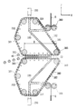
- FIG. 21 shows the other modification in the manufacturing apparatus of the packaged electrode which concerns on this embodiment.
- the stacking drum may have a plurality of rotary rollers 383, instead of a cylindrical shape, which can be flexibly bent and has a suction belt 380 having vents 382.
- the cross section is not limited to a circle, and the outer peripheral surface 381 can have an arbitrary shape, and the design freedom is improved.
- a region B in which the separator 40 and the positive electrode 22 are stacked between the pair of suction belts 380 can be set wide.
- the separator 40 and the positive electrode 22 can be held by the suction belt 380 until the welding by the welding machine is completed, and the welding accuracy can be improved.
- the same reference numerals are used for parts having the same functions as in this embodiment, and the description thereof is omitted.
- the packaged positive electrode 20 a configuration in which the positive electrode 22 is packaged in the separator 40 has been described.
- the negative electrode 30 may be packed by the above-described apparatus for manufacturing a packaged electrode.
- the said embodiment demonstrated the case where the positive electrode lead 11 and the negative electrode lead 12 were derived
- the positive electrode lead 11 and the negative electrode lead 12 may be derived, for example, from opposite ends.
- the negative electrode 30 and the packaged positive electrode 20 are stacked such that the positive electrode tab 23 and the negative electrode tab 33 are in opposite directions.
- a predetermined gap 340 is provided between the pair of upper and lower stacking drums 310 and 320 in the rotary conveyance unit 300.
- the stacking drums 310 and 320 may be in contact with each other and have no gap.
- the positive electrode 22 is conveyed substantially horizontally in the electrode conveyance part 200, you may convey in another direction.
- pair of stacking drums 310 and 320 may be arranged in other directions instead of vertically.
- one continuous separator material S is cut into a predetermined shape in a state of being adsorbed to the outer peripheral surface 311 of the stacking drums 310 and 320 by the separator cutter 351.
- the separators 40 which have been cut into a predetermined shape in advance may be supplied to the stacking drums 310 and 320 and conveyed while being adsorbed.
- a pair of symmetrical laminated drums 310 and 320 are provided.
- the shape of the pair of laminated drums may be asymmetric, and for example, one may be a cylindrical laminated drum and the other may be a suction belt of any shape.
- the stacking drums 310 and 320 have an attracting force, in the configuration in which one separator 40 is stacked on one surface of the positive electrode 22 (or the negative electrode 30), even one stacking drum can sufficiently function. Demonstrate.
- the introductory support part 250 assumed that all were formed of a roller, you may comprise it by another member, such as a flat member.
- the cutting blade provided in the cutting unit 350 may not be a heat cutter, and may be a physically sharp cutting blade.
- the recessed part 313 is provided as a receiving part, a receiving part does not necessarily need to be the recessed part 313. FIG.
- the negative pressure is adjusted to adjust the sliding and the adsorption on the outer peripheral surface 311 of the separator material S.
- the negative pressure of the first negative pressure chamber 331 may be kept substantially constant, and the supply and restraint of the separator material S may be adjusted only by the restraint force of the delivery roller portion 360.
- the adsorption power of the sliding area A1 is lower than the adsorption power of the adsorption area A2.
- the method of applying the adsorption force to the stacking drums 310 and 320 is not limited to the method of adsorption by negative pressure, and may be, for example, adsorption by static electricity.
- the suction unit 370, the negative pressure supply device 333 and the welding unit 400 are synchronized by the control device 500 (synchronization device).
- the control device 500 synchronization device
- not all need to be electrically synchronized for example, at least a part may be mechanically linked and synchronized.
- a joining site is not restricted to an edge and may be except an edge.
- a pair of separators are simultaneously laminated on both sides of the electrode while being transported. Then, by joining the separators in this laminated state, the electrode is bagged by the separator. Therefore, the packaged electrode can be manufactured at high speed, and the manufacturing time of the battery can be shortened.
Abstract
Description
まず、図1を参照して、製造装置により形成されるリチウムイオン二次電池(積層型電池)について説明する。図1はリチウムイオン二次電池の外観を表した斜視図、図2はリチウムイオン二次電池の分解斜視図、図3は袋詰正極および負極の平面図である。
。
次に、本発明の一実施形態に係る袋詰電極の製造装置について、図面を参照しつつ説明する。
、まず、セパレータ40は、積層ドラム310,320の外周面311に吸着され搬送される。この際、積層ドラム310,320の凹部313がセパレータカッター351と対向する位置まで移動すると、セパレータカッター351が制御装置500の指令を受けて積層ドラム310,320の凹部313に侵入するように移動する。これにより、セパレータカッター351がセパレータ40を溶融して、セパレータ40を図3(A)に示すような所定形状に切り出す。セパレータ素材Sからセパレータ40を連続的に切り出す際には、先に切り出すセパレータ40の後端を係合部43が形成される辺44Bとし、次に切り出すセパレータ40の前端を直線的な辺44Aとする。このように、形状が一致しない2辺44A,44Bを切断部350によって同時に切り出すことで、余剰の切取片S’が発生する。
。
20 袋詰正極
22 正極
30 負極
40 セパレータ
42 接合部位
200 電極搬送部
300 回転搬送部
310,320 積層ドラム(円柱状回転体)
311 外周面
400 溶着部(接合部)
500 制御装置(同期装置)
S セパレータ素材(セパレータ)
Claims (4)
- 各々の外周面が対向して並び、セパレータを前記外周面に保持して回転することで搬送する一対の円柱状回転体と、
一対の前記円柱状回転体の間に向かって当該円柱状回転体の接線方向へ所定形状の電極を搬送する電極搬送部と、
一対の前記円柱状回転体によって搬送される一対の前記セパレータの間に前記電極を挟んだ状態で前記セパレータ同士を接合する接合部と、
を有し、
前記電極搬送部によって搬送されている状態の前記電極の両面へ、一対の前記セパレータを回転している前記円柱状回転体から同時に受け渡して積層し、前記電極の両面に受け渡された一対の前記セパレータ同士を前記接合部によって接合することで、前記電極を前記セパレータによって袋詰めすることを特徴とする袋詰電極の製造装置。 - 前記セパレータおよび電極が所定の位置で重なるように、前記円柱状回転体および前記電極搬送部の搬送位置および搬送速度を同期させる同期装置をさらに有し、
前記同期装置によって、前記電極およびセパレータをともに移動させつつ搬送方向の下流側から順次積層することを特徴とする請求項1に記載の袋詰電極の製造装置。 - 各々の外周面が対向して並ぶ一対の円柱状回転体の前記外周面の各々にセパレータを保持して前記円柱状回転体を回転させて搬送する工程と、
一対の前記円柱状回転体の間に向かって当該円柱状回転体の接線方向へ所定形状の電極を搬送する工程と、
一対の前記円柱状回転体の間に搬送されている状態の前記電極の両面へ、一対の前記セパレータを、回転している前記円柱状回転体から同時に受け渡して積層する工程と、
前記電極の両面に受け渡された一対の前記セパレータ同士を接合することで、前記電極を前記セパレータによって袋詰めする工程と、
を有することを特徴とする袋詰電極の製造方法。 - 前記電極は、電極搬送部により、一対の前記円柱状回転体の間に向かって搬送され、
前記セパレータおよび電極が所定の位置で重なるように、前記円柱状回転体および前記電極搬送部の搬送位置および搬送速度を同期させて、前記電極およびセパレータをともに移動させつつ搬送方向の下流側から順次積層することを特徴とする請求項3に記載の袋詰電極の製造方法。
Priority Applications (7)
| Application Number | Priority Date | Filing Date | Title |
|---|---|---|---|
| BR112013025597A BR112013025597A2 (pt) | 2011-04-07 | 2012-04-06 | dispositivo para produção e método para produção de eletrodo embalado |
| EP12767786.2A EP2696405A4 (en) | 2011-04-07 | 2012-04-06 | METHOD OF MANUFACTURING AND DEVICE FOR PRODUCING COATED ELECTRODES |
| RU2013149421/07A RU2552841C1 (ru) | 2011-04-07 | 2012-04-06 | Устройство для получения и способ получения пакетированного электрода |
| CN201280015529XA CN103477470A (zh) | 2011-04-07 | 2012-04-06 | 装袋电极的制造装置和制造方法 |
| KR1020137028556A KR101533183B1 (ko) | 2011-04-07 | 2012-04-06 | 포장 전극의 제조 장치 및 제조 방법 |
| MX2013011460A MX2013011460A (es) | 2011-04-07 | 2012-04-06 | Metod para producir y dispositvo para producir electrodos empacados. |
| US14/008,939 US20140026400A1 (en) | 2011-04-07 | 2012-04-06 | Device for producing and method for producing packaged electrode |
Applications Claiming Priority (4)
| Application Number | Priority Date | Filing Date | Title |
|---|---|---|---|
| JP2011-085741 | 2011-04-07 | ||
| JP2011085741 | 2011-04-07 | ||
| JP2012-067812 | 2012-03-23 | ||
| JP2012067812A JP6022783B2 (ja) | 2011-04-07 | 2012-03-23 | 袋詰電極の製造装置および製造方法 |
Publications (1)
| Publication Number | Publication Date |
|---|---|
| WO2012137904A1 true WO2012137904A1 (ja) | 2012-10-11 |
Family
ID=46969292
Family Applications (1)
| Application Number | Title | Priority Date | Filing Date |
|---|---|---|---|
| PCT/JP2012/059475 WO2012137904A1 (ja) | 2011-04-07 | 2012-04-06 | 袋詰電極の製造装置および製造方法 |
Country Status (10)
| Country | Link |
|---|---|
| US (1) | US20140026400A1 (ja) |
| EP (1) | EP2696405A4 (ja) |
| JP (1) | JP6022783B2 (ja) |
| KR (1) | KR101533183B1 (ja) |
| CN (1) | CN103477470A (ja) |
| BR (1) | BR112013025597A2 (ja) |
| MX (1) | MX2013011460A (ja) |
| RU (1) | RU2552841C1 (ja) |
| TW (1) | TWI458163B (ja) |
| WO (1) | WO2012137904A1 (ja) |
Cited By (5)
| Publication number | Priority date | Publication date | Assignee | Title |
|---|---|---|---|---|
| WO2014087885A1 (ja) * | 2012-12-05 | 2014-06-12 | 日産自動車株式会社 | 電気デバイスのセパレータ切断装置およびその切断方法 |
| ITMO20130311A1 (it) * | 2013-11-11 | 2015-05-12 | Kemet Electronics Italia S R L | Metodo di laminazione |
| CN104838523A (zh) * | 2012-12-05 | 2015-08-12 | 日产自动车株式会社 | 电气装置的隔膜输送装置及其输送方法 |
| CN104854751A (zh) * | 2012-12-28 | 2015-08-19 | 日产自动车株式会社 | 电气装置、电气装置的隔膜接合装置及其接合方法 |
| CN106374144A (zh) * | 2016-10-26 | 2017-02-01 | 广东亿鑫丰智能装备股份有限公司 | 一体化电芯叠片机及电芯叠片方法 |
Families Citing this family (16)
| Publication number | Priority date | Publication date | Assignee | Title |
|---|---|---|---|---|
| JP5954220B2 (ja) * | 2013-02-28 | 2016-07-20 | 株式会社豊田自動織機 | 電極の製造装置、及び電極の製造方法 |
| JP6136883B2 (ja) * | 2013-11-20 | 2017-05-31 | 株式会社豊田自動織機 | 搬送装置 |
| WO2015145551A1 (ja) * | 2014-03-24 | 2015-10-01 | 日産自動車株式会社 | 電気デバイスのセパレータ接合方法および電気デバイスのセパレータ接合装置 |
| KR101575312B1 (ko) | 2014-10-21 | 2015-12-07 | 현대자동차 주식회사 | 연료전지의 막-전극 어셈블리 제조 장치 |
| JP6812971B2 (ja) * | 2015-07-22 | 2021-01-13 | 株式会社豊田自動織機 | リチウムイオン二次電池の電極組立体の製造方法 |
| JP6972822B2 (ja) * | 2017-05-18 | 2021-11-24 | 株式会社豊田自動織機 | 電極搬送装置 |
| JP6984204B2 (ja) * | 2017-07-13 | 2021-12-17 | 株式会社豊田自動織機 | セパレータ付き電極の製造方法 |
| CN107482171A (zh) * | 2017-07-31 | 2017-12-15 | 深圳市格林晟科技有限公司 | 一种电池极片模切制袋叠片一体设备 |
| JP6885310B2 (ja) * | 2017-11-28 | 2021-06-09 | トヨタ自動車株式会社 | 電極シート製造装置および蓄電装置の製造方法 |
| KR102003728B1 (ko) * | 2018-02-13 | 2019-10-01 | 주식회사 이노메트리 | 각형 이차전지용 고속 스택 제조 장치 |
| DE102018215070A1 (de) * | 2018-09-05 | 2020-03-05 | Gs Yuasa International Ltd. | Verfahren zur Bildung eines Elektrodenstapels |
| KR102565054B1 (ko) * | 2019-01-02 | 2023-08-09 | 주식회사 엘지에너지솔루션 | 단위 셀 제조 장치 및 방법 |
| JP7102379B2 (ja) * | 2019-09-17 | 2022-07-19 | 株式会社東芝 | 袋詰電極の製造装置、集積装置および袋詰電極の製造方法 |
| CN111293367B (zh) * | 2020-03-19 | 2021-08-20 | 闫延 | 一种锂电池封口装置 |
| CN112117495A (zh) * | 2020-10-20 | 2020-12-22 | 深圳吉阳智能科技有限公司 | 叠片设备、方法及叠片结构 |
| CN114614065B (zh) * | 2022-03-10 | 2024-03-29 | 重庆瑞点新能源科技有限公司 | 一种绿色电池自动包装胶合装置 |
Citations (9)
| Publication number | Priority date | Publication date | Assignee | Title |
|---|---|---|---|---|
| JPS5190030U (ja) * | 1975-01-16 | 1976-07-19 | ||
| JPS60165050A (ja) * | 1984-02-07 | 1985-08-28 | Matsushita Electric Ind Co Ltd | 極板とセパレ−タの組立て装置 |
| JPH06203839A (ja) * | 1992-12-25 | 1994-07-22 | Fuji Elelctrochem Co Ltd | 電池用の帯状電極とセパレータとをスパイラル状に巻き込んで成形する装置 |
| JPH10275628A (ja) * | 1997-03-28 | 1998-10-13 | Japan Storage Battery Co Ltd | 電池の製造方法 |
| JP2002100394A (ja) * | 2000-09-21 | 2002-04-05 | Denso Corp | セパレータ付き電極の製造方法および電池の製造方法並びにセパレータと電極との積層装置 |
| JP2006324095A (ja) * | 2005-05-18 | 2006-11-30 | Nec Tokin Corp | 二次電池及びその製造方法 |
| JP2006331796A (ja) * | 2005-05-25 | 2006-12-07 | Shin Kobe Electric Mach Co Ltd | セパレータ被覆電極の製造装置 |
| JP2007242506A (ja) * | 2006-03-10 | 2007-09-20 | Litcel Kk | リチウムイオン電池並びにその製造方法及び製造装置 |
| JP2007329111A (ja) | 2006-06-09 | 2007-12-20 | Litcel Kk | リチウムイオン電池並びにその製造方法及び製造装置並びに袋入り電極板の製造方法及び製造装置 |
Family Cites Families (10)
| Publication number | Priority date | Publication date | Assignee | Title |
|---|---|---|---|---|
| JP4157999B2 (ja) * | 1999-11-09 | 2008-10-01 | ソニー株式会社 | 電極及びゲル状電解質電池の製造方法 |
| JP3710669B2 (ja) * | 2000-02-25 | 2005-10-26 | 本田技研工業株式会社 | 電池用捲回電極の製造方法 |
| US6503658B1 (en) * | 2001-07-11 | 2003-01-07 | Electro Energy, Inc. | Bipolar electrochemical battery of stacked wafer cells |
| RU2343593C2 (ru) * | 2004-05-31 | 2009-01-10 | Ниссан Мотор Ко., Лтд. | Сборный аккумулятор и способ его изготовления |
| JP5048404B2 (ja) * | 2007-06-29 | 2012-10-17 | 東レエンジニアリング株式会社 | 2次電池の製造方法および製造装置 |
| JP4362539B2 (ja) * | 2007-07-20 | 2009-11-11 | パナソニック株式会社 | 電池用電極板、電池用極板群、リチウム二次電池、電池用電極板の製造方法、及び電池用電極板の製造装置 |
| RU2379670C1 (ru) * | 2008-10-17 | 2010-01-20 | Федеральное государственное унитарное предприятие "Обнинское научно-производственное предприятие "Технология" | Электрохимический элемент и способ его изготовления |
| EP2455997B1 (en) * | 2009-07-14 | 2017-08-30 | Kawasaki Jukogyo Kabushiki Kaisha | Method for producing a fiber battery and a facility for producing a fiber battery |
| JP5383471B2 (ja) * | 2009-12-22 | 2014-01-08 | 三菱重工業株式会社 | 電極製造システム |
| JP5522851B2 (ja) * | 2010-11-25 | 2014-06-18 | 株式会社京都製作所 | 極板包装装置 |
-
2012
- 2012-03-23 JP JP2012067812A patent/JP6022783B2/ja active Active
- 2012-04-06 CN CN201280015529XA patent/CN103477470A/zh active Pending
- 2012-04-06 KR KR1020137028556A patent/KR101533183B1/ko not_active IP Right Cessation
- 2012-04-06 EP EP12767786.2A patent/EP2696405A4/en not_active Withdrawn
- 2012-04-06 MX MX2013011460A patent/MX2013011460A/es active IP Right Grant
- 2012-04-06 BR BR112013025597A patent/BR112013025597A2/pt not_active IP Right Cessation
- 2012-04-06 WO PCT/JP2012/059475 patent/WO2012137904A1/ja active Application Filing
- 2012-04-06 TW TW101112285A patent/TWI458163B/zh not_active IP Right Cessation
- 2012-04-06 US US14/008,939 patent/US20140026400A1/en not_active Abandoned
- 2012-04-06 RU RU2013149421/07A patent/RU2552841C1/ru not_active IP Right Cessation
Patent Citations (9)
| Publication number | Priority date | Publication date | Assignee | Title |
|---|---|---|---|---|
| JPS5190030U (ja) * | 1975-01-16 | 1976-07-19 | ||
| JPS60165050A (ja) * | 1984-02-07 | 1985-08-28 | Matsushita Electric Ind Co Ltd | 極板とセパレ−タの組立て装置 |
| JPH06203839A (ja) * | 1992-12-25 | 1994-07-22 | Fuji Elelctrochem Co Ltd | 電池用の帯状電極とセパレータとをスパイラル状に巻き込んで成形する装置 |
| JPH10275628A (ja) * | 1997-03-28 | 1998-10-13 | Japan Storage Battery Co Ltd | 電池の製造方法 |
| JP2002100394A (ja) * | 2000-09-21 | 2002-04-05 | Denso Corp | セパレータ付き電極の製造方法および電池の製造方法並びにセパレータと電極との積層装置 |
| JP2006324095A (ja) * | 2005-05-18 | 2006-11-30 | Nec Tokin Corp | 二次電池及びその製造方法 |
| JP2006331796A (ja) * | 2005-05-25 | 2006-12-07 | Shin Kobe Electric Mach Co Ltd | セパレータ被覆電極の製造装置 |
| JP2007242506A (ja) * | 2006-03-10 | 2007-09-20 | Litcel Kk | リチウムイオン電池並びにその製造方法及び製造装置 |
| JP2007329111A (ja) | 2006-06-09 | 2007-12-20 | Litcel Kk | リチウムイオン電池並びにその製造方法及び製造装置並びに袋入り電極板の製造方法及び製造装置 |
Non-Patent Citations (1)
| Title |
|---|
| See also references of EP2696405A4 |
Cited By (18)
| Publication number | Priority date | Publication date | Assignee | Title |
|---|---|---|---|---|
| CN104838523B (zh) * | 2012-12-05 | 2016-08-24 | 日产自动车株式会社 | 电气装置的隔膜输送装置及其输送方法 |
| US9941500B2 (en) | 2012-12-05 | 2018-04-10 | Nissan Motor Co., Ltd. | Conveying apparatus and a conveying method of separator of electric device |
| WO2014087885A1 (ja) * | 2012-12-05 | 2014-06-12 | 日産自動車株式会社 | 電気デバイスのセパレータ切断装置およびその切断方法 |
| CN104838523A (zh) * | 2012-12-05 | 2015-08-12 | 日产自动车株式会社 | 电气装置的隔膜输送装置及其输送方法 |
| US9492939B2 (en) | 2012-12-05 | 2016-11-15 | Nissan Motor Co., Ltd. | Cutting apparatus for separator of electrical device |
| KR101564537B1 (ko) | 2012-12-05 | 2015-10-29 | 닛산 지도우샤 가부시키가이샤 | 전기 디바이스의 세퍼레이터 절단 장치 및 그 절단 방법 |
| JP5983767B2 (ja) * | 2012-12-05 | 2016-09-06 | 日産自動車株式会社 | 電気デバイスのセパレータ切断装置およびその切断方法 |
| JPWO2014103594A1 (ja) * | 2012-12-28 | 2017-01-12 | 日産自動車株式会社 | 電気デバイスおよび電気デバイスのセパレータ接合方法 |
| EP2940775A4 (en) * | 2012-12-28 | 2016-02-17 | Nissan Motor | ELECTRICAL DEVICE AND DEVICE AND METHOD FOR A BONDSEPARATOR OF THE ELECTRICAL DEVICE |
| JP5994866B2 (ja) * | 2012-12-28 | 2016-09-21 | 日産自動車株式会社 | 電気デバイスおよび電気デバイスのセパレータ接合方法 |
| CN104854751A (zh) * | 2012-12-28 | 2015-08-19 | 日产自动车株式会社 | 电气装置、电气装置的隔膜接合装置及其接合方法 |
| US9799910B2 (en) | 2012-12-28 | 2017-10-24 | Nissan Motor Co., Ltd. | Welding apparatus and a welding method for separator of electrical device |
| CN105917511A (zh) * | 2013-11-11 | 2016-08-31 | 曼兹意大利有限责任公司 | 层压方法 |
| WO2015068143A1 (en) * | 2013-11-11 | 2015-05-14 | Manz Italy S.R.L. | Laminating method |
| ITMO20130311A1 (it) * | 2013-11-11 | 2015-05-12 | Kemet Electronics Italia S R L | Metodo di laminazione |
| US10020541B2 (en) | 2013-11-11 | 2018-07-10 | Manz Italy S.R.L. | Laminating method |
| CN106374144A (zh) * | 2016-10-26 | 2017-02-01 | 广东亿鑫丰智能装备股份有限公司 | 一体化电芯叠片机及电芯叠片方法 |
| CN106374144B (zh) * | 2016-10-26 | 2023-06-16 | 广东亿鑫丰智能装备股份有限公司 | 一体化电芯叠片机及电芯叠片方法 |
Also Published As
| Publication number | Publication date |
|---|---|
| TW201310756A (zh) | 2013-03-01 |
| RU2552841C1 (ru) | 2015-06-10 |
| BR112013025597A2 (pt) | 2016-12-27 |
| JP2012227125A (ja) | 2012-11-15 |
| KR20140002016A (ko) | 2014-01-07 |
| US20140026400A1 (en) | 2014-01-30 |
| KR101533183B1 (ko) | 2015-07-01 |
| EP2696405A1 (en) | 2014-02-12 |
| EP2696405A4 (en) | 2014-12-24 |
| MX2013011460A (es) | 2013-10-17 |
| CN103477470A (zh) | 2013-12-25 |
| TWI458163B (zh) | 2014-10-21 |
| JP6022783B2 (ja) | 2016-11-09 |
| RU2013149421A (ru) | 2015-05-20 |
Similar Documents
| Publication | Publication Date | Title |
|---|---|---|
| WO2012137904A1 (ja) | 袋詰電極の製造装置および製造方法 | |
| JP5901135B2 (ja) | 積層装置および積層方法 | |
| JP5893461B2 (ja) | 位置検出装置および位置検出方法 | |
| WO2012137922A1 (ja) | セパレータ搬送装置およびセパレータ搬送方法 | |
| JP5706743B2 (ja) | 積層装置および積層方法 | |
| JP2012221707A (ja) | セパレータ搬送装置およびセパレータ搬送方法 | |
| JP5827027B2 (ja) | セパレータ搬送装置およびセパレータ搬送方法 |
Legal Events
| Date | Code | Title | Description |
|---|---|---|---|
| 121 | Ep: the epo has been informed by wipo that ep was designated in this application |
Ref document number: 12767786 Country of ref document: EP Kind code of ref document: A1 |
|
| WWE | Wipo information: entry into national phase |
Ref document number: 14008939 Country of ref document: US |
|
| WWE | Wipo information: entry into national phase |
Ref document number: MX/A/2013/011460 Country of ref document: MX Ref document number: 2012767786 Country of ref document: EP |
|
| NENP | Non-entry into the national phase |
Ref country code: DE |
|
| ENP | Entry into the national phase |
Ref document number: 20137028556 Country of ref document: KR Kind code of ref document: A |
|
| ENP | Entry into the national phase |
Ref document number: 2013149421 Country of ref document: RU Kind code of ref document: A |
|
| REG | Reference to national code |
Ref country code: BR Ref legal event code: B01A Ref document number: 112013025597 Country of ref document: BR |
|
| ENP | Entry into the national phase |
Ref document number: 112013025597 Country of ref document: BR Kind code of ref document: A2 Effective date: 20131003 |