WO2012133383A1 - 自動車用トルクアーム - Google Patents
自動車用トルクアーム Download PDFInfo
- Publication number
- WO2012133383A1 WO2012133383A1 PCT/JP2012/057886 JP2012057886W WO2012133383A1 WO 2012133383 A1 WO2012133383 A1 WO 2012133383A1 JP 2012057886 W JP2012057886 W JP 2012057886W WO 2012133383 A1 WO2012133383 A1 WO 2012133383A1
- Authority
- WO
- WIPO (PCT)
- Prior art keywords
- outer cylinder
- bush
- rubber
- space
- torque arm
- Prior art date
- Legal status (The legal status is an assumption and is not a legal conclusion. Google has not performed a legal analysis and makes no representation as to the accuracy of the status listed.)
- Ceased
Links
Images






Classifications
-
- B—PERFORMING OPERATIONS; TRANSPORTING
- B29—WORKING OF PLASTICS; WORKING OF SUBSTANCES IN A PLASTIC STATE IN GENERAL
- B29C—SHAPING OR JOINING OF PLASTICS; SHAPING OF MATERIAL IN A PLASTIC STATE, NOT OTHERWISE PROVIDED FOR; AFTER-TREATMENT OF THE SHAPED PRODUCTS, e.g. REPAIRING
- B29C45/00—Injection moulding, i.e. forcing the required volume of moulding material through a nozzle into a closed mould; Apparatus therefor
- B29C45/14—Injection moulding, i.e. forcing the required volume of moulding material through a nozzle into a closed mould; Apparatus therefor incorporating preformed parts or layers, e.g. injection moulding around inserts or for coating articles
- B29C45/14336—Coating a portion of the article, e.g. the edge of the article
- B29C45/14344—Moulding in or through a hole in the article, e.g. outsert moulding
-
- F—MECHANICAL ENGINEERING; LIGHTING; HEATING; WEAPONS; BLASTING
- F16—ENGINEERING ELEMENTS AND UNITS; GENERAL MEASURES FOR PRODUCING AND MAINTAINING EFFECTIVE FUNCTIONING OF MACHINES OR INSTALLATIONS; THERMAL INSULATION IN GENERAL
- F16F—SPRINGS; SHOCK-ABSORBERS; MEANS FOR DAMPING VIBRATION
- F16F1/00—Springs
- F16F1/36—Springs made of rubber or other material having high internal friction, e.g. thermoplastic elastomers
- F16F1/38—Springs made of rubber or other material having high internal friction, e.g. thermoplastic elastomers with a sleeve of elastic material between a rigid outer sleeve and a rigid inner sleeve or pin, i.e. bushing-type
- F16F1/3807—Springs made of rubber or other material having high internal friction, e.g. thermoplastic elastomers with a sleeve of elastic material between a rigid outer sleeve and a rigid inner sleeve or pin, i.e. bushing-type characterised by adaptations for particular modes of stressing
- F16F1/3821—Springs made of rubber or other material having high internal friction, e.g. thermoplastic elastomers with a sleeve of elastic material between a rigid outer sleeve and a rigid inner sleeve or pin, i.e. bushing-type characterised by adaptations for particular modes of stressing characterised by adaptations to counter torsional forces
-
- B—PERFORMING OPERATIONS; TRANSPORTING
- B29—WORKING OF PLASTICS; WORKING OF SUBSTANCES IN A PLASTIC STATE IN GENERAL
- B29C—SHAPING OR JOINING OF PLASTICS; SHAPING OF MATERIAL IN A PLASTIC STATE, NOT OTHERWISE PROVIDED FOR; AFTER-TREATMENT OF THE SHAPED PRODUCTS, e.g. REPAIRING
- B29C45/00—Injection moulding, i.e. forcing the required volume of moulding material through a nozzle into a closed mould; Apparatus therefor
- B29C45/14—Injection moulding, i.e. forcing the required volume of moulding material through a nozzle into a closed mould; Apparatus therefor incorporating preformed parts or layers, e.g. injection moulding around inserts or for coating articles
- B29C45/14467—Joining articles or parts of a single article
-
- B—PERFORMING OPERATIONS; TRANSPORTING
- B60—VEHICLES IN GENERAL
- B60K—ARRANGEMENT OR MOUNTING OF PROPULSION UNITS OR OF TRANSMISSIONS IN VEHICLES; ARRANGEMENT OR MOUNTING OF PLURAL DIVERSE PRIME-MOVERS IN VEHICLES; AUXILIARY DRIVES FOR VEHICLES; INSTRUMENTATION OR DASHBOARDS FOR VEHICLES; ARRANGEMENTS IN CONNECTION WITH COOLING, AIR INTAKE, GAS EXHAUST OR FUEL SUPPLY OF PROPULSION UNITS IN VEHICLES
- B60K1/00—Arrangement or mounting of electrical propulsion units
-
- B—PERFORMING OPERATIONS; TRANSPORTING
- B60—VEHICLES IN GENERAL
- B60K—ARRANGEMENT OR MOUNTING OF PROPULSION UNITS OR OF TRANSMISSIONS IN VEHICLES; ARRANGEMENT OR MOUNTING OF PLURAL DIVERSE PRIME-MOVERS IN VEHICLES; AUXILIARY DRIVES FOR VEHICLES; INSTRUMENTATION OR DASHBOARDS FOR VEHICLES; ARRANGEMENTS IN CONNECTION WITH COOLING, AIR INTAKE, GAS EXHAUST OR FUEL SUPPLY OF PROPULSION UNITS IN VEHICLES
- B60K5/00—Arrangement or mounting of internal-combustion or jet-propulsion units
- B60K5/12—Arrangement of engine supports
- B60K5/1241—Link-type support
-
- F—MECHANICAL ENGINEERING; LIGHTING; HEATING; WEAPONS; BLASTING
- F16—ENGINEERING ELEMENTS AND UNITS; GENERAL MEASURES FOR PRODUCING AND MAINTAINING EFFECTIVE FUNCTIONING OF MACHINES OR INSTALLATIONS; THERMAL INSULATION IN GENERAL
- F16F—SPRINGS; SHOCK-ABSORBERS; MEANS FOR DAMPING VIBRATION
- F16F1/00—Springs
- F16F1/36—Springs made of rubber or other material having high internal friction, e.g. thermoplastic elastomers
- F16F1/38—Springs made of rubber or other material having high internal friction, e.g. thermoplastic elastomers with a sleeve of elastic material between a rigid outer sleeve and a rigid inner sleeve or pin, i.e. bushing-type
- F16F1/3842—Method of assembly, production or treatment; Mounting thereof
- F16F1/3849—Mounting brackets therefor, e.g. stamped steel brackets; Restraining links
-
- B—PERFORMING OPERATIONS; TRANSPORTING
- B29—WORKING OF PLASTICS; WORKING OF SUBSTANCES IN A PLASTIC STATE IN GENERAL
- B29C—SHAPING OR JOINING OF PLASTICS; SHAPING OF MATERIAL IN A PLASTIC STATE, NOT OTHERWISE PROVIDED FOR; AFTER-TREATMENT OF THE SHAPED PRODUCTS, e.g. REPAIRING
- B29C45/00—Injection moulding, i.e. forcing the required volume of moulding material through a nozzle into a closed mould; Apparatus therefor
- B29C45/14—Injection moulding, i.e. forcing the required volume of moulding material through a nozzle into a closed mould; Apparatus therefor incorporating preformed parts or layers, e.g. injection moulding around inserts or for coating articles
- B29C45/14336—Coating a portion of the article, e.g. the edge of the article
- B29C45/14344—Moulding in or through a hole in the article, e.g. outsert moulding
- B29C2045/1436—Moulding in or through a hole in the article, e.g. outsert moulding coating hollow articles having holes passing through the wall
-
- B—PERFORMING OPERATIONS; TRANSPORTING
- B29—WORKING OF PLASTICS; WORKING OF SUBSTANCES IN A PLASTIC STATE IN GENERAL
- B29K—INDEXING SCHEME ASSOCIATED WITH SUBCLASSES B29B, B29C OR B29D, RELATING TO MOULDING MATERIALS OR TO MATERIALS FOR MOULDS, REINFORCEMENTS, FILLERS OR PREFORMED PARTS, e.g. INSERTS
- B29K2021/00—Use of unspecified rubbers as moulding material
-
- Y—GENERAL TAGGING OF NEW TECHNOLOGICAL DEVELOPMENTS; GENERAL TAGGING OF CROSS-SECTIONAL TECHNOLOGIES SPANNING OVER SEVERAL SECTIONS OF THE IPC; TECHNICAL SUBJECTS COVERED BY FORMER USPC CROSS-REFERENCE ART COLLECTIONS [XRACs] AND DIGESTS
- Y10—TECHNICAL SUBJECTS COVERED BY FORMER USPC
- Y10T—TECHNICAL SUBJECTS COVERED BY FORMER US CLASSIFICATION
- Y10T74/00—Machine element or mechanism
- Y10T74/21—Elements
- Y10T74/2142—Pitmans and connecting rods
-
- Y—GENERAL TAGGING OF NEW TECHNOLOGICAL DEVELOPMENTS; GENERAL TAGGING OF CROSS-SECTIONAL TECHNOLOGIES SPANNING OVER SEVERAL SECTIONS OF THE IPC; TECHNICAL SUBJECTS COVERED BY FORMER USPC CROSS-REFERENCE ART COLLECTIONS [XRACs] AND DIGESTS
- Y10—TECHNICAL SUBJECTS COVERED BY FORMER USPC
- Y10T—TECHNICAL SUBJECTS COVERED BY FORMER US CLASSIFICATION
- Y10T74/00—Machine element or mechanism
- Y10T74/21—Elements
- Y10T74/2142—Pitmans and connecting rods
- Y10T74/2162—Engine type
Definitions
- the present invention relates to an automotive torque arm that can support a power plant by connecting a power plant serving as a power source to the vehicle body.
- the power source mounted on the automobile is connected to the vehicle body by an automobile torque arm (hereinafter simply referred to as a torque arm).
- the torque arm includes a first bush coupled to the vehicle body, a second bush coupled to the power source, and a coupling portion coupling the first bush and the second bush.
- the first inner cylinder is coaxially arranged inside the first outer cylinder, and the first rubber elastic body is interposed in the first space between the first outer cylinder and the first inner cylinder.
- the second inner cylinder is coaxially arranged inside the second outer cylinder, and the second rubber elastic body is interposed in the second space between the second outer cylinder and the second inner cylinder.
- the first outer cylinder of the first bush and the second outer cylinder of the second bush are connected by a connecting portion to form a torque arm.
- Some torque arms include a pair of halves formed by dividing the first outer cylinder, the second outer cylinder, and the connecting portion into two members (see, for example, Patent Document 1).
- a pair of halves are overlapped to form a first outer cylinder, a second outer cylinder, and a connecting portion. With the pair of halves overlapped, the first inner cylinder is disposed inside the first outer cylinder, and the second inner cylinder is disposed inside the second outer cylinder.
- the pair of overlapped halves and the first and second inner cylinders are accommodated in the mold cavity.
- the cavity is filled with a rubber material, and the filled rubber material is vulcanized (crosslinked).
- the first rubber elastic body is formed in the first space with the vulcanized rubber formed by vulcanization to form the first bush, and the second rubber elastic body is formed in the second space to form the second bush.
- the vulcanization molding of the torque arm is completed by bonding the pair of halves with vulcanized rubber.
- An object of the present invention is to provide a torque arm for an automobile in which a torque arm arranged so that an axis of a first bush and an axis of a second bush intersect each other can be vulcanized.
- the first bush provided with the first rubber elastic body in the first space between the first outer cylinder and the first inner cylinder, and between the second outer cylinder and the second inner cylinder.
- a second rubber elastic body is provided in the second space, and a second bush arranged to intersect the first bush, and the second outer cylinder of the second bush are connected to the first bush of the first bush.
- a second half is formed in the half, and a rubber introduction port communicating with the second space is formed in the introduction portion on the flat portion side of the second outer cylinder, and the first half and the In a state where the first outer cylinder, the second outer cylinder, and the outer cylinder connecting portion are formed by overlapping the second halves, it is poured so as to intersect the flat portion of the outer cylinder connecting portion.
- the outer cylinder connecting portion is covered with the rubber material, and the rubber material is guided to the flat portion and led to the rubber inlet, and the guided rubber material passes through the rubber inlet and is
- the second rubber elastic body is formed of the rubber material filled in the second space and filled in the second space. Automotive torque arm that is provided.
- the second bush is arranged so as to intersect the first bush. Therefore, the opening of the second space of the second bush is displaced by approximately 90 ° with respect to the first space of the first bush. For this reason, when the opening part of 1st space is made to oppose with the filling channel
- the flat portion of the connecting portion is formed parallel to the axis of the second bush. Therefore, the flat part of a connection part can be arrange
- the outer cylinder connecting portion is formed so that a width dimension of the flat portion decreases as it goes from the first bush to the second bush. There is a throttle part in the vicinity.
- the second outer cylinder of the second bush is formed to have a smaller diameter than the first outer cylinder of the first bush, and the second bush is connected to the power source, The first bush is connected to the vehicle body.
- the flat portion of the connecting portion is formed in parallel to the axis of the second bush. Therefore, the flat part of a connection part can be arrange
- a rubber introduction port communicating with the second space was formed in the introduction portion on the flat portion side of the second outer cylinder.
- the first rubber elastic body is formed (molded) in the first space
- the second rubber elastic body is formed in the second space ( Molding). Accordingly, it is possible to vulcanize (crosslink) the automobile torque arm disposed so that the axis of the first bush and the axis of the second bush intersect each other.
- the bonds between the molecules of the first rubber elastic body and the second rubber elastic body are strengthened, and the elasticity and tensile strength are increased. Can do.
- the width of the flat portion is reduced as it goes from the first bush to the second bush, and the throttle portion is formed in the vicinity of the second bush.
- an introduction path of the rubber material is formed between the half of the connecting portion and the remaining half of the connecting portion, and the rubber material injected into the first space passes through the introduction path and passes through the first passage. It can be considered to lead to two spaces.
- the introduction path has a smaller width dimension than the flat part. For this reason, by reducing the width dimension of the flat portion, the flow passage cross section of the introduction path becomes smaller as it goes from the first bush to the second bush, and becomes particularly small at the throttle portion. For this reason, it is difficult to smoothly guide the rubber material guided from the first space to the introduction path toward the second space.
- the torque arm according to claim 2 is configured such that a rubber introduction port is formed in the introduction portion on the flat portion side of the second outer cylinder, and the rubber material is guided from the rubber introduction port to the second space. Yes.
- the rubber material can be smoothly and reliably guided to the second space even in the torque arm in which the width of the flat portion is reduced as it goes from the first bush to the second bush.
- the second outer cylinder of the second bush is formed to have a smaller diameter than the first outer cylinder of the first bush, and the second bush having the smaller diameter is connected to a power source (power plant).
- the second bush is disposed so as to intersect the first bush. Therefore, the 2nd bush is connected with the power source in the state where the axis was arranged in parallel.
- the lower part of the second bush can be arranged at a high position by reducing the diameter of the second bush.
- the lower part of the second bush is usually located below the lower part of the power source. Thereby, the minimum ground clearance around a power source can be ensured high by arranging the lower part of the 2nd bush in a high position.
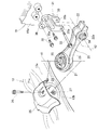
- FIG. 1 is a perspective view showing a front vehicle body provided with a torque arm according to an embodiment of the present invention. It is the disassembled perspective view which showed the relationship between the torque arm shown by FIG. 1, a front sub-frame, and a power plant.
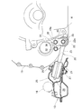
- FIG. 3 is a cross-sectional view taken along line 3-3 in FIG.
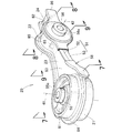
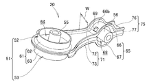
- FIG. 3 is a perspective view of the torque arm shown in FIG. 2.
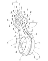
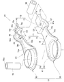
- FIG. 5 is a perspective view showing upper and lower halves of the torque arm shown in FIG. 4.
- FIG. 6 is an exploded perspective view of the upper and lower halves shown in FIG. 5.
- FIG. 7 is a cross-sectional view taken along line 7-7 in FIG.
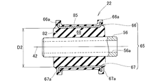
- FIG. 8 is a sectional view taken along line 8-8 in FIG.
- FIG. 9 is a cross-sectional view taken along line 9-9 in FIG. It is a perspective view of a torque arm when upper and lower halves are overlapped and stored in a mold. It is sectional drawing which showed the state which accommodated the torque arm shown by FIG. 10 in the metal mold
- a front vehicle body 10 of a vehicle includes left and right side frames 11 and 12 arranged in the front-rear direction of the vehicle body, and front subframes attached below the left and right side frames 11 and 12 ( Vehicle body) 13, a steering gear box 16 attached to the upper portion 13 a of the front sub-frame 13, and a torque arm 20 that connects the front sub-frame 13 and a power plant (power source) 19.
- the front sub-frame 13 is formed in a substantially rectangular shape in plan view, and a left front attachment portion 13c and a left rear attachment portion 13d are provided at the left end portion, and a right front attachment portion 13e and a right rear attachment portion 13f are provided at the right end portion. ing.
- the left front attachment portion 13 c and the left rear attachment portion 13 d are attached to the left side frame 11.
- the right front attachment portion 13e and the right rear attachment portion 13f are attached to the right side frame 12.
- the steering gear box 16 is a cylindrical case that houses a steering gear (not shown).
- the steering gear box 16 is attached to the upper portion 13a of the front subframe 13 so as to extend in the vehicle width direction.
- a steering wheel 18 is attached to a steering shaft 17 extending from the steering gear box 16.
- the wall portion 19a of the power plant 19 is connected to the center portion 13b in the vehicle width direction of the upper portion 13a of the front subframe 13 via the torque arm 20.
- the power plant 19 is an engine / transmission unit in which an engine and a transmission are integrally formed and disposed sideways between the left and right side frames 11 and 12.
- the power plant 19 is attached to the left side frame 11 via a left mounting bracket, and is attached to the right side frame 12 via a right mounting bracket.
- the second outer cylinder 65 (see FIG. 5) of the second bush 22 is formed with a smaller diameter than the first outer cylinder 61 (see FIG. 5) of the first bush 21. Furthermore, it arrange
- the torque arm 20 includes a first bush 21, a second bush 22, a connecting portion 23, and an overhang portion 24.
- the torque arm 20 includes an aggregate member 51 that secures the rigidity of the torque arm 20, a first inner cylinder 55 and a second inner cylinder 56 disposed on the bone member 51, and a first inner cylinder 55 and a second inner cylinder. It is comprised by 4 members with the rubber elastic body 58 which provides 56 in the connection part 23 integrally.
- the bone member 51, the first inner cylinder 55, and the second inner cylinder 56 are integrally bonded with a rubber elastic body 58.
- the bone member 51 is divided into the upper half 52 and the lower half 53, so that the outer cylinder connecting portion 71 becomes the upper outer cylinder connecting portion (one half) 72 and the lower outer cylinder connecting portion ( The other half 73) is divided into halves.
- the outer cylinder overhang 75 is half of the upper outer cylinder overhang 76 and the lower outer cylinder overhang 77. It is divided into.
- the rubber introduction port 69 is an opening that is provided in the vicinity of the upper flat portion 72a of the upper outer cylinder connecting portion 72 and communicates the space on the upper flat portion 72a side with the second space 68.
- the second lower outer cylinder 67 is formed in a semi-annular shape having a diameter D2 by bulging downward.
- the second lower outer cylinder 67 has a curved lower projecting piece 67a projecting downward from both ends.
- the upper outer cylinder coupling part (one half part) 72 and the lower outer cylinder coupling part (the other half part) 73 into which the outer cylinder coupling part 71 is divided are vertically symmetrical members.
- the upper outer cylinder connecting portion 72 is formed such that the width dimension W of the upper flat portion (flat portion) 72a becomes smaller from the first upper outer cylinder 62 toward the second upper outer cylinder 66. ing.
- an upper diaphragm portion (diaphragm portion) 72c is formed in the vicinity of the second upper outer cylinder 66.
- the upper outer cylinder connecting portion 72 is formed in a substantially U-shaped cross section by the upper protruding pieces 72b protruding upward from both sides of the upper flat portion 72a (see FIG. 9).
- the upper outer cylinder connecting portion 72 and the lower outer cylinder connecting portion 73 are formed in a substantially U-shaped cross section. Therefore, the upper outer cylinder coupling portion 72 and the lower outer cylinder coupling portion 73 are overlapped to form an outer cylinder coupling portion 71 having a substantially H-shaped cross section.
- the upper outer cylinder connecting portion 72 and the lower outer cylinder connecting portion 73 can be formed so that the width dimension W of the upper flat portion 72a and the lower flat portion 73a is gradually reduced. It is. Therefore, the selection range can be expanded when determining the shapes of the upper outer cylinder connecting portion 72 and the lower outer cylinder connecting portion 73, that is, the shape of the torque arm 20. Thereby, it becomes possible to make a torque arm respond
- the lower outer cylinder projecting portion 77 has lower projecting pieces 77b projecting downward from both sides of the lower flat portion 77a. Accordingly, the lower outer cylinder overhanging portion 77 is formed in a substantially U-shaped cross section with the lower flat portion 77a and the pair of lower overhanging pieces 77b, like the lower outer cylinder coupling portion 73. As a result, the upper outer cylinder overhanging portion 76 and the lower outer cylinder overhanging portion 77 are overlapped to form an outer cylinder overhanging portion 75 having a substantially H-shaped cross section.
- the first inner cylinder 55 has a first hollow portion 55a that can penetrate the bolt 26 (FIG. 2) by being formed in a cylindrical shape. As shown in FIG. 2, the first inner cylinder 55 is connected to the central portion 13 b by passing the bolt 26 through the first hollow portion 55 a and attaching the bolt 26 to the central portion 13 b of the front subframe 13.
- the second outer cylinder 65 is formed by the second upper outer cylinder 66 and the second lower outer cylinder 67 in a state where the upper half body 52 and the lower half body 53 are overlapped.
- the A second inner cylinder 56 is coaxially disposed in the second outer cylinder 65. In this state, a second space 68 is formed between the second outer cylinder 65 and the second inner cylinder 56.
- the rubber elastic body 58 includes a first rubber elastic body 81 provided in a first space 64 between the first outer cylinder 61 and the first inner cylinder 55, and a second outer cylinder 65. And a second rubber elastic body 82 provided in the second space 68 between the second inner cylinders 56 and a third rubber elastic body 83 covering the outer cylinder connecting portion 71. Further, the rubber elastic body 58 covers the fourth rubber elastic body 84 that covers the outside of the first outer cylinder 61, the fifth rubber elastic body 85 that covers the outside of the second outer cylinder 65, and the outer cylinder overhang 75. And a sixth rubber elastic body 86.
- the first rubber elastic body 81 is provided in the first space 64 between the first outer cylinder 61 and the first inner cylinder 55, and the outer peripheral portion of the first outer cylinder 61 is the fourth rubber elastic.
- the first bush 21 is formed by being covered with the body 84.
- the first bush 21 is formed such that the axis 41 is directed in a substantially vertical direction.
- the second rubber elastic body 82 is provided in the second space 68 between the second outer cylinder 65 and the second inner cylinder 56, and the outer peripheral portion of the second outer cylinder 65 is the fifth rubber elastic.
- the second bush 22 is formed by being covered with the body 85.
- the second bush 22 is disposed so as to intersect (orthogonally) the first bush 21. Therefore, the 2nd bush 22 is formed so that the axis line 42 may face in a substantially horizontal direction.
- the outer cylinder coupling portion 71 is covered with a third rubber elastic body 83.
- the outer cylinder coupling portion 71 is covered with the third rubber elastic body 83, so that the outer cylinder coupling portion 71 and the third rubber elastic body 83 form the coupling portion 23.
- the outer cylinder connecting portion 71 has an upper flat portion 72 a and a lower flat portion 73 a that connect the second bush 22 to the first bush 21.
- the upper flat portion 72 a and the lower flat portion 73 a intersect with the axis 41 of the first bush 21 and are arranged in parallel with the axis 42 of the second bush 22. ing. Therefore, the upper flat portion 72 a is disposed in parallel to the opening portion 64 a of the first space 64.
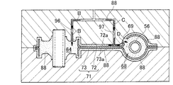
- the opening 64a of the first space 64 can be opposed to the first runner 96 (see FIG. 12), and the upper flat portion 72a can be opposed to the second runner 97 (see FIG. 12). Accordingly, the rubber material 88 (see FIG. 12) is filled in the first space 64, and the rubber material 88 can be guided to the upper flat portion 72a.
- a rubber inlet 69 is formed in the vicinity of the upper flat portion 72a. Accordingly, the rubber material 88 guided to the upper flat portion 72a can be guided to the rubber introduction port 69 by the upper flat portion 72a, and the guided rubber material 88 can be filled into the second space 68 from the rubber introduction port 69. .
- the bonds between the respective molecules of the first rubber elastic body 81 and the second rubber elastic body 82 are strengthened, and Elasticity and tensile strength can be increased.
- the outer cylinder projecting portion 75 is covered with a sixth rubber elastic body 86.
- the outer cylinder overhang 75 is covered with the sixth rubber elastic body 86, so that the outer cylinder overhang 75 is integrally bonded with the sixth rubber elastic body 86.
- the rubber material 88 is injected so as to intersect the upper flat portion 72a of the upper outer cylinder connecting portion 72.
- the outer cylinder connecting portion 71 is covered with the rubber material 88 injected from the second runner 97 into the cavity 93.
- the upper outer cylinder connecting portion 72 and the lower outer cylinder connecting portion 73 are formed such that the width dimension W (FIG. 10) of the upper and lower flat portions 72a and 73a decreases as it goes from the first bush 21 to the second bush 22. .
- an upper throttle part 72 c (FIG. 6) is formed in the vicinity of the second upper outer cylinder 66, and a lower throttle part 73 c (FIG. 6) is formed in the vicinity of the second lower outer cylinder 67.
- the introduction path has a smaller width dimension than the flat part.
- a rubber introduction port 69 is formed in the introduction portion 66 b on the upper outer cylinder coupling portion 72 side of the second upper outer cylinder 66. Yes. Therefore, the rubber material 88 (FIG. 12) can be guided from the rubber introduction port 69 to the second space 68. Thereby, even in the torque arm 20 in which the width dimension W (FIG. 10) of the upper and lower flat portions 72a and 73a is formed small, the rubber material 88 is smoothly and reliably guided from the rubber introduction port 69 to the second space 68. be able to.
- the third rubber elastic body 83 is vulcanized to cover the outer cylinder connecting portion 71 (FIG. 10) with the third rubber elastic body 83.
- the connecting portion 23 is formed by the outer cylinder connecting portion 71 and the third rubber elastic body 83.
- the sixth rubber elastic body 86 is vulcanized to cover the outer cylinder projecting portion 75 (FIG. 10) with the sixth rubber elastic body 86.
- the overhang portion 24 is formed by the outer cylinder overhang portion 75 and the sixth rubber elastic body 86.
- the torque arm 110 of the modification shown in FIGS. 14 and 15 is provided with a reinforcing ring 112 coaxially inside the second outer cylinder 65, and the other configuration is the same as the torque arm 20 of the embodiment.
- the reinforcing ring 112 is formed in a cylindrical shape (annular shape) so as to be coaxially accommodated inside the second outer cylinder 65.
- the reinforcing ring 112 has a ring introduction port 113 formed in a portion 112 a facing the rubber introduction port 69 of the second upper outer cylinder 66.
- the ring inlet 113 is formed in substantially the same shape as the rubber inlet 69.
- the outer peripheral surface 112b of the reinforcing ring 112 is in contact with the inner surface 65a of the second outer cylinder 65.
- the rubber material 88 (FIG. 12) is filled in the second space 68 between the second outer cylinder 65 and the second inner cylinder 56.
- the second outer cylinder 65, the reinforcing ring 112, and the second inner cylinder 56 are integrally provided by the rubber material 88 (that is, the second rubber elastic body 82) filled in the second space 68.
- the ring introduction port 113 of the reinforcing ring 112 is formed to face the rubber introduction port 69.
- the rubber material 88 guided to the rubber introduction port 69 along the upper flat portion 72 a is guided to the ring introduction port 113 through the rubber introduction port 69. it can.
- the rubber material 88 guided to the ring introduction port 113 is filled into the second space 68 through the ring introduction port 113.
- the second rubber elastic body 82 (FIG. 13) can be vulcanized and molded with the rubber material 88 filled in the second space 68.
- the torque arm according to the present invention is not limited to the above-described embodiments, and can be changed or improved as appropriate.
- the example in which the first inner cylinder 55 of the first bush 21 is attached to the front subframe 13 and the second inner cylinder 56 of the second bush 22 is attached to the power plant 19 has been described. Not what you want.
- the second arm 22 is provided with the overhanging portion 24 in the torque arms 20 and 110 has been described.
- the embodiment is not limited thereto, and the overhanging portion 24 can be removed.
- the shapes and configurations of the rubber elastic body 81 and the second rubber elastic body 82 are not limited to those illustrated, and can be appropriately changed.
- lower second outer cylinder (the other half), 68 ... second space, 69 ... rubber inlet, 71 ... outer cylinder connection 72, upper outer cylinder connecting part (one half), 72a ... upper flat part (flat part), 72c ... upper throttle part (throttle part), 73 ... lower outer cylinder connecting part ( Half), 73a ... lower flat part (flat part), 73c ... lower throttle part (throttle part), 81 ... first rubber elastic body, 82 ... second rubber elastic body, 88 ... rubber material, D1 ... first. 1 diameter of outer cylinder, D2... Diameter of second outer cylinder.
Landscapes
- Engineering & Computer Science (AREA)
- Mechanical Engineering (AREA)
- General Engineering & Computer Science (AREA)
- Manufacturing & Machinery (AREA)
- Transportation (AREA)
- Combustion & Propulsion (AREA)
- Chemical & Material Sciences (AREA)
- Health & Medical Sciences (AREA)
- Child & Adolescent Psychology (AREA)
- Vibration Prevention Devices (AREA)
- Vehicle Body Suspensions (AREA)
- Arrangement Or Mounting Of Propulsion Units For Vehicles (AREA)
- Springs (AREA)
- Injection Moulding Of Plastics Or The Like (AREA)
Abstract
Description
図4に示すように、トルクアーム20は、第1ブッシュ21、第2ブッシュ22、連結部23および張出部24を備えている。このトルクアーム20は、トルクアーム20の剛性を確保する骨材部材51と、骨部材51に配置された第1内筒55および第2内筒56と、第1内筒55および第2内筒56を連結部23に一体に設けるゴム弾性体58との4部材で構成されている。骨部材51、第1内筒55および第2内筒56はゴム弾性体58で一体に接着されている。
図10に示すように、上半割体52および下半割体53を重ね合わせて、第1外筒61、第2外筒65、外筒連結部71および外筒張出部75を形成する。第1外筒61の内部に第1内筒55を同軸上に配置し、第2外筒65の内部に第2内筒56を同軸上に配置する。
Claims (3)
- 第1外筒および第1内筒間の第1空間に第1ゴム弾性体が設けられた第1ブッシュと、
第2外筒および第2内筒間の第2空間に第2ゴム弾性体が設けられ、前記第1ブッシュに対して交差するように配置された第2ブッシュと、
前記第2ブッシュの前記第2外筒を前記第1ブッシュの前記第1外筒に連結する外筒連結部を有し、前記外筒連結部の平坦部が前記第1ブッシュの軸線に対して交差するとともに前記第2ブッシュの軸線に対して平行に形成された連結部と、
を備え、前記第1ブッシュおよび前記第2ブッシュの一方が動力源に連結され、他方が車体に連結された自動車用トルクアームであって、
前記第1外筒、前記第2外筒および前記外筒連結部がそれぞれ半分に分割され、
分割された前記第1外筒、前記第2外筒および前記外筒連結部の一方の半部で第1半割体が形成され、
分割された前記第1外筒、前記第2外筒および前記外筒連結部の他方の半部で第2半割体が形成され、
前記第2外筒のうち前記平坦部側の導入部位に、前記第2空間に連通するゴム導入口が形成され、
前記第1半割体および前記第2半割体を重ね合わせて前記第1外筒、前記第2外筒および前記外筒連結部が形成された状態において、前記外筒連結部の前記平坦部に向けて交差するように流し込まれたゴム材料で前記外筒連結部が被覆されるとともに、前記ゴム材料が前記平坦部に案内されて前記ゴム導入口に導かれ、導かれた前記ゴム材料が前記ゴム導入口を経て前記第2空間に充填され、前記第2空間に充填された前記ゴム材料で前記第2ゴム弾性体が形成されることを特徴とする自動車用トルクアーム。 - 前記外筒連結部は、前記第1ブッシュから前記第2ブッシュに向かうにつれて前記平坦部の幅寸法が小さくなるように形成されることにより前記第2ブッシュの近傍に絞り部を有する、請求項1に記載の自動車用トルクアーム。
- 前記第2ブッシュの前記第2外筒は前記第1ブッシュの前記第1外筒より小径に形成され、前記第2ブッシュは前記動力源に連結され、前記第1ブッシュは前記車体に連結されている、請求項1に記載の自動車用トルクアーム。
Priority Applications (3)
| Application Number | Priority Date | Filing Date | Title |
|---|---|---|---|
| CN201280015082.6A CN103459882B (zh) | 2011-03-31 | 2012-03-27 | 机动车用扭臂 |
| US14/007,796 US8967599B2 (en) | 2011-03-31 | 2012-03-27 | Torque arm for automobile |
| JP2013507595A JP5597308B2 (ja) | 2011-03-31 | 2012-03-27 | 自動車用トルクアーム |
Applications Claiming Priority (2)
| Application Number | Priority Date | Filing Date | Title |
|---|---|---|---|
| JP2011-080686 | 2011-03-31 | ||
| JP2011080686 | 2011-03-31 |
Publications (1)
| Publication Number | Publication Date |
|---|---|
| WO2012133383A1 true WO2012133383A1 (ja) | 2012-10-04 |
Family
ID=46931100
Family Applications (1)
| Application Number | Title | Priority Date | Filing Date |
|---|---|---|---|
| PCT/JP2012/057886 Ceased WO2012133383A1 (ja) | 2011-03-31 | 2012-03-27 | 自動車用トルクアーム |
Country Status (4)
| Country | Link |
|---|---|
| US (1) | US8967599B2 (ja) |
| JP (1) | JP5597308B2 (ja) |
| CN (1) | CN103459882B (ja) |
| WO (1) | WO2012133383A1 (ja) |
Cited By (3)
| Publication number | Priority date | Publication date | Assignee | Title |
|---|---|---|---|---|
| JP2014173682A (ja) * | 2013-03-11 | 2014-09-22 | Mitsubishi Motors Corp | ロールロッド |
| US20150008305A1 (en) * | 2013-07-04 | 2015-01-08 | Ford Global Technologies, Llc | System for reducing engine roll |
| JP2016223550A (ja) * | 2015-06-01 | 2016-12-28 | 株式会社ブリヂストン | 防振装置 |
Families Citing this family (10)
| Publication number | Priority date | Publication date | Assignee | Title |
|---|---|---|---|---|
| JP5913848B2 (ja) * | 2011-07-13 | 2016-04-27 | 日産自動車株式会社 | トルクロッド |
| DE112014006527T5 (de) * | 2014-03-28 | 2016-12-22 | Sumitomo Riko Company Limited | Rohrförmige Schwingungsdämpfungsvorrichtung mit Verwendung für eine Schwingungsdämpfungsverbindungsstange Schwingungsdämpfungsverbindungsstange mit Verwendung derselben sowie Verfahren zum Herstellen einer Schwingungsdämpfungsverbindungsstange |
| CN104589988A (zh) * | 2014-12-18 | 2015-05-06 | 重庆小康工业集团股份有限公司 | 发动机悬置 |
| JP2017024531A (ja) * | 2015-07-21 | 2017-02-02 | スズキ株式会社 | トルクロッドの取付け構造 |
| US9815361B2 (en) * | 2015-07-29 | 2017-11-14 | Fca Us Llc | Split bushing torque strut isolator assembly |
| US10308102B2 (en) * | 2017-02-07 | 2019-06-04 | Vibracoustic Usa, Inc. | Damped torque roll restrictor |
| FR3068649B1 (fr) * | 2017-07-10 | 2021-11-26 | Renault Sas | Dispositif monobloc de support d'un groupe motopropulseur integrant un palier relais |
| JP6683754B2 (ja) * | 2018-04-11 | 2020-04-22 | 本田技研工業株式会社 | 駆動源の支持構造 |
| US11505312B2 (en) * | 2019-04-22 | 2022-11-22 | Lockheed Martin Corporation | Main rotor damper elastomeric rod end |
| KR102681926B1 (ko) * | 2019-07-29 | 2024-07-04 | 현대자동차 주식회사 | 차량의 구동장치와 조향장치의 차체 장착구조 |
Citations (5)
| Publication number | Priority date | Publication date | Assignee | Title |
|---|---|---|---|---|
| JPS57100640U (ja) * | 1980-12-10 | 1982-06-21 | ||
| JPS6056841U (ja) * | 1983-09-26 | 1985-04-20 | 本田技研工業株式会社 | ラバ−マウント装置 |
| JP2003206991A (ja) * | 2002-01-10 | 2003-07-25 | Tokai Rubber Ind Ltd | 防振装置及びこれに用いる金具と防振装置の製造方法 |
| JP2005163844A (ja) * | 2003-11-28 | 2005-06-23 | Tokai Rubber Ind Ltd | トルクロッド |
| JP2007078050A (ja) * | 2005-09-13 | 2007-03-29 | Kurashiki Kako Co Ltd | 防振装置及びその製造方法 |
Family Cites Families (12)
| Publication number | Priority date | Publication date | Assignee | Title |
|---|---|---|---|---|
| US4706946A (en) * | 1985-11-25 | 1987-11-17 | Thorn Richard P | Motion control strut |
| JPH1163109A (ja) * | 1997-08-21 | 1999-03-05 | Marugo Rubber Kogyo Kk | 防振装置及びその製造方法 |
| FR2805869B1 (fr) * | 2000-03-02 | 2002-06-14 | Hutchinson | Manchon antivibratoire, bielle comportant un tel manchon, et procede de fabrication |
| JP4046093B2 (ja) * | 2004-03-19 | 2008-02-13 | 東海ゴム工業株式会社 | 樹脂トルクロッドの製造方法 |
| JP4046094B2 (ja) * | 2004-03-19 | 2008-02-13 | 東海ゴム工業株式会社 | トルクロッド |
| JP4560376B2 (ja) * | 2004-10-29 | 2010-10-13 | 東海ゴム工業株式会社 | スタビライザブッシュ |
| JP4491790B2 (ja) * | 2005-08-26 | 2010-06-30 | 東海ゴム工業株式会社 | 防振連結ロッド |
| JP4881781B2 (ja) * | 2007-03-30 | 2012-02-22 | 東海ゴム工業株式会社 | トルクロッドの製造方法 |
| US20090230601A1 (en) * | 2008-03-14 | 2009-09-17 | Gm Global Technology Operations, Inc. | Biaxial Exhaust Isolator With Dual-Band Reinforcement |
| JP2009234300A (ja) * | 2008-03-25 | 2009-10-15 | Tokai Rubber Ind Ltd | トルクロッド |
| JP2009243483A (ja) * | 2008-03-28 | 2009-10-22 | Tokai Rubber Ind Ltd | 樹脂トルクロッド |
| JP2010038195A (ja) * | 2008-07-31 | 2010-02-18 | Tokai Rubber Ind Ltd | トルクロッド及びその製造方法 |
-
2012
- 2012-03-27 US US14/007,796 patent/US8967599B2/en active Active
- 2012-03-27 JP JP2013507595A patent/JP5597308B2/ja not_active Expired - Fee Related
- 2012-03-27 CN CN201280015082.6A patent/CN103459882B/zh not_active Expired - Fee Related
- 2012-03-27 WO PCT/JP2012/057886 patent/WO2012133383A1/ja not_active Ceased
Patent Citations (5)
| Publication number | Priority date | Publication date | Assignee | Title |
|---|---|---|---|---|
| JPS57100640U (ja) * | 1980-12-10 | 1982-06-21 | ||
| JPS6056841U (ja) * | 1983-09-26 | 1985-04-20 | 本田技研工業株式会社 | ラバ−マウント装置 |
| JP2003206991A (ja) * | 2002-01-10 | 2003-07-25 | Tokai Rubber Ind Ltd | 防振装置及びこれに用いる金具と防振装置の製造方法 |
| JP2005163844A (ja) * | 2003-11-28 | 2005-06-23 | Tokai Rubber Ind Ltd | トルクロッド |
| JP2007078050A (ja) * | 2005-09-13 | 2007-03-29 | Kurashiki Kako Co Ltd | 防振装置及びその製造方法 |
Cited By (5)
| Publication number | Priority date | Publication date | Assignee | Title |
|---|---|---|---|---|
| JP2014173682A (ja) * | 2013-03-11 | 2014-09-22 | Mitsubishi Motors Corp | ロールロッド |
| US20150008305A1 (en) * | 2013-07-04 | 2015-01-08 | Ford Global Technologies, Llc | System for reducing engine roll |
| CN104276022A (zh) * | 2013-07-04 | 2015-01-14 | 福特环球技术公司 | 用于降低发动机滚动的系统 |
| US9242542B2 (en) * | 2013-07-04 | 2016-01-26 | Ford Global Technologies, Llc | System for reducing engine roll |
| JP2016223550A (ja) * | 2015-06-01 | 2016-12-28 | 株式会社ブリヂストン | 防振装置 |
Also Published As
| Publication number | Publication date |
|---|---|
| JPWO2012133383A1 (ja) | 2014-07-28 |
| US8967599B2 (en) | 2015-03-03 |
| CN103459882A (zh) | 2013-12-18 |
| CN103459882B (zh) | 2015-05-20 |
| US20140015177A1 (en) | 2014-01-16 |
| JP5597308B2 (ja) | 2014-10-01 |
Similar Documents
| Publication | Publication Date | Title |
|---|---|---|
| JP5597308B2 (ja) | 自動車用トルクアーム | |
| US8523258B2 (en) | Mounting of subframe | |
| CN204037255U (zh) | 由纤维增强塑料制得的用于汽车车轮悬架的横向导臂 | |
| JP5905091B2 (ja) | 鞍乗り型車両 | |
| JP2010101385A (ja) | ブッシュ | |
| WO2019087945A1 (ja) | 電動パワーステアリング装置用ギヤハウジングおよびその製造方法、並びに、電動パワーステアリング装置 | |
| CN103661632B (zh) | 由复合材料的两个管道和支柱构成的机动车辆的仪表盘横梁 | |
| WO2015166841A1 (ja) | トランスミッション | |
| US7469912B2 (en) | Bracket of steering rack housing | |
| KR20210010494A (ko) | 조인트 및 상기 조인트의 제조 방법 | |
| JP4909379B2 (ja) | シャシ構成部材 | |
| JP2009115109A (ja) | 防振連結ロッド | |
| JP6184097B2 (ja) | 自動二輪車のスイングアーム支持構造 | |
| WO2012042752A1 (ja) | トーコレクトブッシュ | |
| CN101883694A (zh) | 模块化燃料箱及其制造方法 | |
| KR20180076788A (ko) | 플라스틱 재질의 롤마운트 브라켓 | |
| JP2011168087A (ja) | 自動車用のトルクロッド | |
| JP4607938B2 (ja) | 防振連結ロッド | |
| JP5437025B2 (ja) | 防振装置 | |
| JP2005163844A (ja) | トルクロッド | |
| JP2008051200A (ja) | ブッシュの製造方法 | |
| JP5318731B2 (ja) | 防振装置 | |
| KR102653063B1 (ko) | 전기 차량용 후륜 서브 프레임 | |
| JP3950041B2 (ja) | 二重管部材の成形方法及び二重管部材 | |
| JP4598725B2 (ja) | 防振装置取付用ブラケット |
Legal Events
| Date | Code | Title | Description |
|---|---|---|---|
| 121 | Ep: the epo has been informed by wipo that ep was designated in this application |
Ref document number: 12764682 Country of ref document: EP Kind code of ref document: A1 |
|
| ENP | Entry into the national phase |
Ref document number: 2013507595 Country of ref document: JP Kind code of ref document: A |
|
| WWE | Wipo information: entry into national phase |
Ref document number: 14007796 Country of ref document: US |
|
| NENP | Non-entry into the national phase |
Ref country code: DE |
|
| 122 | Ep: pct application non-entry in european phase |
Ref document number: 12764682 Country of ref document: EP Kind code of ref document: A1 |