WO2012133218A1 - 基板処理装置 - Google Patents
基板処理装置 Download PDFInfo
- Publication number
- WO2012133218A1 WO2012133218A1 PCT/JP2012/057578 JP2012057578W WO2012133218A1 WO 2012133218 A1 WO2012133218 A1 WO 2012133218A1 JP 2012057578 W JP2012057578 W JP 2012057578W WO 2012133218 A1 WO2012133218 A1 WO 2012133218A1
- Authority
- WO
- WIPO (PCT)
- Prior art keywords
- substrate
- atmospheric
- transfer
- chamber
- vacuum
- Prior art date
- Legal status (The legal status is an assumption and is not a legal conclusion. Google has not performed a legal analysis and makes no representation as to the accuracy of the status listed.)
- Ceased
Links
Images




Classifications
-
- H—ELECTRICITY
- H10—SEMICONDUCTOR DEVICES; ELECTRIC SOLID-STATE DEVICES NOT OTHERWISE PROVIDED FOR
- H10P—GENERIC PROCESSES OR APPARATUS FOR THE MANUFACTURE OR TREATMENT OF DEVICES COVERED BY CLASS H10
- H10P72/00—Handling or holding of wafers, substrates or devices during manufacture or treatment thereof
- H10P72/30—Handling or holding of wafers, substrates or devices during manufacture or treatment thereof for conveying, e.g. between different workstations
- H10P72/32—Handling or holding of wafers, substrates or devices during manufacture or treatment thereof for conveying, e.g. between different workstations between different workstations
-
- H—ELECTRICITY
- H10—SEMICONDUCTOR DEVICES; ELECTRIC SOLID-STATE DEVICES NOT OTHERWISE PROVIDED FOR
- H10P—GENERIC PROCESSES OR APPARATUS FOR THE MANUFACTURE OR TREATMENT OF DEVICES COVERED BY CLASS H10
- H10P72/00—Handling or holding of wafers, substrates or devices during manufacture or treatment thereof
- H10P72/04—Apparatus for manufacture or treatment
- H10P72/0451—Apparatus for manufacturing or treating in a plurality of work-stations
- H10P72/0452—Apparatus for manufacturing or treating in a plurality of work-stations characterised by the layout of the process chambers
- H10P72/0456—Apparatus for manufacturing or treating in a plurality of work-stations characterised by the layout of the process chambers in-line arrangement
-
- H—ELECTRICITY
- H10—SEMICONDUCTOR DEVICES; ELECTRIC SOLID-STATE DEVICES NOT OTHERWISE PROVIDED FOR
- H10P—GENERIC PROCESSES OR APPARATUS FOR THE MANUFACTURE OR TREATMENT OF DEVICES COVERED BY CLASS H10
- H10P72/00—Handling or holding of wafers, substrates or devices during manufacture or treatment thereof
- H10P72/04—Apparatus for manufacture or treatment
- H10P72/0451—Apparatus for manufacturing or treating in a plurality of work-stations
- H10P72/0461—Apparatus for manufacturing or treating in a plurality of work-stations characterised by the presence of two or more transfer chambers
-
- H—ELECTRICITY
- H10—SEMICONDUCTOR DEVICES; ELECTRIC SOLID-STATE DEVICES NOT OTHERWISE PROVIDED FOR
- H10P—GENERIC PROCESSES OR APPARATUS FOR THE MANUFACTURE OR TREATMENT OF DEVICES COVERED BY CLASS H10
- H10P72/00—Handling or holding of wafers, substrates or devices during manufacture or treatment thereof
- H10P72/04—Apparatus for manufacture or treatment
- H10P72/0451—Apparatus for manufacturing or treating in a plurality of work-stations
- H10P72/0466—Apparatus for manufacturing or treating in a plurality of work-stations characterised by the construction of the load-lock chamber
-
- H—ELECTRICITY
- H10—SEMICONDUCTOR DEVICES; ELECTRIC SOLID-STATE DEVICES NOT OTHERWISE PROVIDED FOR
- H10P—GENERIC PROCESSES OR APPARATUS FOR THE MANUFACTURE OR TREATMENT OF DEVICES COVERED BY CLASS H10
- H10P72/00—Handling or holding of wafers, substrates or devices during manufacture or treatment thereof
- H10P72/70—Handling or holding of wafers, substrates or devices during manufacture or treatment thereof for supporting or gripping
- H10P72/78—Handling or holding of wafers, substrates or devices during manufacture or treatment thereof for supporting or gripping using vacuum or suction, e.g. Bernoulli chucks
Definitions
- the present invention relates to a multi-chamber system substrate processing apparatus including a plurality of processing chambers for processing a substrate in a reduced pressure atmosphere.
- a plurality of vacuum processing apparatuses that perform substrate processing such as film formation processing, etching processing, oxidation diffusion processing, annealing processing, and modification processing on a semiconductor wafer are provided around the vacuum transfer chamber,
- a multi-chamber type substrate processing apparatus configured to transfer a wafer between vacuum processing chambers and continuously perform required substrate processing has been put into practical use. As described above, the throughput of the substrate processing can be improved by clustering a plurality of vacuum processing apparatuses.
- Patent Document 1 two clustered multi-chamber apparatuses are connected in series via a gate valve, and a tandem-type substrate processing provided with a transfer chamber for transferring a wafer between vacuum transfer chambers of each cluster.
- An apparatus is disclosed.
- the first cluster is provided with a load lock chamber, and wafers are carried into the vacuum transfer chamber of the first cluster via the load lock chamber.
- the wafers carried into the vacuum transfer chamber are sequentially subjected to substrate processing by each vacuum processing apparatus constituting the first cluster.
- the substrate processing is sequentially performed in the second cluster.
- the processed wafer is unloaded by following the same path as the forward path in reverse order.
- Patent Document 2 only a vacuum processing chamber that requires delivery of a substrate under a reduced pressure atmosphere is connected to a vacuum transfer chamber to form a cluster, and a vacuum processing chamber capable of delivering a substrate under an atmospheric atmosphere is provided around the atmosphere transfer chamber.
- a substrate processing apparatus configured to be connected to each other via a load lock chamber is disclosed.
- a substrate processing apparatus is disclosed in which two clusters are arranged in parallel along the transfer direction of the atmospheric transfer mechanism, and a wafer supplied from the outside is transferred to the load lock chamber of each cluster.
- the substrate processing apparatus according to Patent Document 1 has a problem in that the wafer transfer throughput decreases due to the wafer transfer between the load lock chamber and each cluster. If the vacuum transfer mechanism is rate limiting, the throughput of substrate processing cannot be improved even if the number of clusters is increased.
- the substrate processing apparatus has a configuration in which two clusters are juxtaposed along the transfer direction of the atmospheric transfer mechanism that transfers the wafer supplied through the load port to the load lock chamber of each cluster.
- the atmospheric transfer mechanism becomes longer in the transfer direction. If the atmospheric conveyance mechanism is lengthened, the throughput of the atmospheric conveyance mechanism may be reduced.
- the atmospheric transfer mechanism transfers wafers directly to and from each cluster via the load lock chamber, wafers can be transferred simultaneously in each load lock chamber. If required, the wafers cannot be delivered individually, and the throughput may be reduced.
- the present invention has been made in view of such circumstances, and provides a substrate processing apparatus capable of reducing the occupied space, shortening the inoperable time of the entire apparatus, and improving the throughput of the substrate processing. Objective.
- a substrate processing apparatus includes a plurality of processing chambers in which a plurality of processing chambers for processing a substrate in a reduced-pressure atmosphere are close to each other, and a transport mechanism that carries the substrate in and out of the plurality of processing chambers.
- a vacuum transfer chamber is provided in each of the vacuum transfer chambers of the plurality of vacuum transfer chambers, and the substrate is transferred to and from the vacuum transfer chamber by switching between the atmospheric atmosphere and the reduced-pressure atmosphere.
- a first atmospheric transfer mechanism for transferring a substrate supplied from the outside to the one load-lock chamber, and a substrate received from the first atmospheric transfer mechanism
- a second atmospheric transfer mechanism for transferring to the load lock chamber, and the second atmospheric transfer mechanism is disposed on the upper side or the lower side of the vacuum transfer chamber provided with the one load lock.
- Vacuum transfer chamber characterized in that it is arranged in series along the conveying direction of the substrate by the second atmospheric transfer mechanism.
- the present invention it is possible to reduce the occupied space and the inoperable time of the entire apparatus and improve the substrate processing throughput.
- FIG. 10 is a side sectional view schematically showing a configuration example of a substrate processing apparatus according to Modification 1.
- 10 is a side cross-sectional view schematically showing a configuration example of a substrate processing apparatus according to Modification 2.
- FIG. 10 is a side cross-sectional view schematically showing a configuration example of a substrate processing apparatus according to Modification 3.
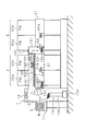
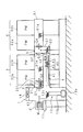
- FIG. 1 is a plan sectional view schematically showing a configuration example of a substrate processing apparatus according to an embodiment of the present invention
- FIG. 2 schematically shows a configuration example of the substrate processing apparatus according to the embodiment
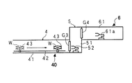
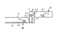
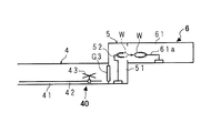
- FIG. 3 is an explanatory view schematically showing the operation of the second atmospheric transfer mechanism 40 and the second load lock device 5 according to the present embodiment.
- the substrate processing apparatus according to the embodiment of the present invention includes a first atmospheric transfer device 1, a first load lock device 2, a first cluster 3, a second atmospheric transfer device 4, and a second load lock device 5. , And a second cluster 6.
- the first atmospheric transfer device 1 has a first atmospheric transfer chamber 12 that is a horizontally long substantially rectangular parallelepiped. On one side wall of the long side of the first atmospheric transfer chamber 12, a load port 11 is provided for transferring the wafer W to and from a transfer vehicle (not shown) that travels outside. A transfer vehicle (not shown) transfers a cassette C containing a plurality of unprocessed wafers W to the substrate processing apparatus.
- the load port 11 includes a mounting table on which the cassette C containing the wafer W is mounted, and a mechanism that connects the cassette C to the first atmospheric transfer chamber 12 and opens and closes the cassette C.
- a first cluster 3 is connected to a side wall of the first atmospheric transfer chamber 12 facing the one side wall via a first load lock device 2, and via a second atmospheric transfer device 4 and a second load lock device 5.
- the second cluster 6 is connected.
- the wafer W is taken out from the cassette C placed on the load port 11, and the taken wafer W is transferred to the first load lock device 2 and the second atmospheric transfer device 4.
- 1 atmospheric conveyance mechanism 13 is provided.
- the first atmospheric transfer mechanism 13 includes a guide rail 13a laid along the longitudinal direction of the bottom of the first atmospheric transfer chamber 12, and an atmospheric robot 13b movable along the guide rail 13a. Yes.
- the atmospheric robot 13b has a plurality of extendable and articulated articulated arms provided with forks for holding and transporting the wafer W, and a drive mechanism (not shown) that moves the articulated arms up and down and pivots. .
- the atmospheric robot 13b moves along the guide rail 13a by, for example, a linear motor mechanism, and takes out the wafer W from the cassette C placed on the load port 11 by moving the articulated arm to extend, move up and down, and turn.
- the wafer W is transferred to the first load lock device 2 and the second atmospheric transfer device 4. Further, the wafer W processed and transferred in the first cluster 3 and the second cluster 6 is received from the first load lock device 2 and the second atmospheric transfer device 4 and returned to the cassette C.
- a first air blowing unit 14 that blows clean gas to the first atmospheric transfer chamber 12 is provided at an appropriate location of the first atmospheric transfer chamber 12.
- the first load lock device 2 has a first load lock chamber 21 connected to a vacuum pump, and can be switched between an air atmosphere and a reduced pressure atmosphere by evacuating or releasing the air.
- a first load lock chamber 21 On the first atmospheric transfer device 1 side and the first cluster 3 side of the first load lock chamber 21, gates G1 and G2 that can be opened and closed are respectively provided.
- a first transfer robot 22 At the bottom of the first load lock chamber 21, there is provided a first transfer robot 22 that loads and unloads the wafer W between the first atmospheric transfer chamber 12 and the first cluster 3 through gates G1 and G2.
- the first transfer robot 22 is a vacuum robot having an articulated arm provided with a fork for holding the wafer W.
- the gate G1 is opened by setting the first load lock chamber 21 to the atmospheric atmosphere, and the first transfer robot 22 is connected to the first transfer robot 22 via the gate G1.
- the wafer W is carried into the first load lock chamber 21 from the atmospheric transfer chamber 12, and the gate G1 is closed.
- the first load lock chamber 21 is evacuated to a reduced pressure atmosphere, and the gate G2 is opened.
- the first transfer robot 22 transfers the wafer W to the first vacuum transfer chamber 31 (to be described later) of the first cluster 3 through the gate G2.
- the transfer is performed in the reverse procedure.
- the example which delivers the wafer W using the 1st conveyance robot 22 was demonstrated here, it replaces with the 1st conveyance robot 22, and you may comprise so that the stage which goes up and down may be provided.
- the first atmospheric transfer mechanism 13 and the first vacuum transfer mechanism 31a can deliver and transfer the wafer W by placing the wafer W on the stage.
- the first cluster 3 has a first vacuum transfer chamber 31 that is a horizontally long substantially rectangular parallelepiped.
- the first vacuum transfer chamber 31 is arranged so that its longitudinal direction is substantially orthogonal to the transfer direction of the first atmospheric transfer mechanism 13.
- a gate G ⁇ b> 2 is connected to one side wall on the short side of the first vacuum transfer chamber 31.
- Four first vacuum processing chambers (PM: Process Module) 32a, 32b, 32c, and 32d are connected to both side walls on the long side of the first vacuum transfer chamber 31 shown in FIG. Has been.
- four first vacuum processing chambers are provided, but the present invention is not limited to this, and any number may be provided.
- the first vacuum processing chambers 32a, 32b, 32c, and 32d are used for substrate processing such as film processing, etching processing, oxidation diffusion processing, annealing processing, and modification processing on the semiconductor wafer W in a reduced-pressure atmosphere. It is a device that performs.
- a first vacuum transfer mechanism 31a that carries the wafer W through the gate G2 and transfers the wafer W to each vacuum processing chamber according to the recipe.
- the first vacuum transfer mechanism 31a is a vacuum robot having two articulated arms provided with a fork for holding the wafer W.
- the first vacuum transfer mechanism 13 carries out the processed wafer W to the first load lock chamber 21 through the gate G2.
- the second atmospheric transfer device 4 has a second atmospheric transfer chamber 41 that is a horizontally long substantially rectangular parallelepiped disposed below the first vacuum transfer chamber 31.
- the second atmospheric transfer chamber 41 is arranged such that its longitudinal direction is substantially orthogonal to the transfer direction of the first atmospheric transfer device 1.
- a second atmospheric transfer mechanism 40 that receives a substrate from the first atmospheric transfer mechanism 13 and transfers the received substrate to the second load lock device 5 is provided.
- the second atmospheric transfer mechanism 40 has a guide rail 42 laid along the longitudinal direction at the bottom of the second atmospheric transfer chamber 41.
- a substantially X-shaped wafer holding member 43 that holds the wafer W transferred from the first atmospheric transfer device 1 and transfers it to the second load lock device 5 is movable along the guide rail 42.
- the wafer holding member 43 is driven by a linear motor, for example, and moves along the guide rail 42.
- a second air blower 44 that blows clean gas to the second atmospheric transfer chamber 41 is provided at an appropriate location of the second atmospheric transfer chamber 41.
- the second atmospheric transfer mechanism 40 moves the wafer holding member 43 to the first atmospheric transfer device 1 side.
- the first atmospheric transfer mechanism 13 (see FIG. 1) holds the wafer W on the wafer holding member 43.
- the wafer holding member 43 holding the wafer W moves toward the second load lock device 5 along the guide rail 42 as shown in FIG. 3B.
- the wafer W held by the wafer holding member 43 is received by the second transfer robot 52 provided in the second load lock device 5 described later.
- the wafer W When the wafer W is moved from the second load lock device 5 to the first atmospheric transfer device 1, the wafer W may be transferred in the reverse procedure.
- the second load lock device 5 has a second load lock chamber 51 that is a vertically long and substantially rectangular parallelepiped connected to a vacuum pump. It can be switched between an air atmosphere and a reduced pressure atmosphere.
- a gate G3 and a gate G4 that can be opened and closed are provided on the lower side wall of the second load lock chamber 51 on the second atmospheric transfer device 4 side and the upper side wall on the second cluster 6 side, respectively.
- a second transfer robot 52 for loading and unloading the wafer W between the second atmospheric transfer chamber 41 and the second cluster 6 through the gate G3 and the gate G4 is provided. Yes.
- the second transfer robot 52 is a vacuum robot having an articulated arm provided with a fork for holding the wafer W.
- the second transfer robot 52 has a drive mechanism (not shown) that moves the articulated arm up and down and pivots.
- the gate G3 is opened with the second load lock chamber 51 in the atmospheric atmosphere, and the second transfer robot 52 The wafer W is carried into the second load lock chamber 51 from the second atmospheric transfer chamber 41 via G3, and the gate G3 is closed. Then, the second load lock chamber 51 is evacuated to a reduced pressure atmosphere.
- the second transfer robot 52 raises the wafer W and opens the gate G4.
- the second transfer robot 52 transfers the wafer W to the second vacuum transfer chamber 61 (described later) of the second cluster 6 through the gate G4.
- the example which delivers the wafer W using the 2nd conveyance robot 52 was demonstrated here, it may replace with the 2nd conveyance robot 52, and you may comprise so that the stage which goes up and down may be provided.
- the second atmospheric transfer mechanism 40 and the second vacuum transfer mechanism 61a can deliver and transfer the wafer W by placing the wafer W on the stage and moving the stage up and down.
- the second cluster 6 has a second vacuum transfer chamber 61 that is a substantially rectangular parallelepiped.
- the second vacuum transfer chamber 61 is arranged in series so that the longitudinal direction thereof substantially coincides with the longitudinal direction of the first vacuum transfer chamber 31. That is, the first vacuum transfer chamber 31 and the second vacuum transfer chamber 61 are arranged in series along the transfer direction of the wafer W by the second atmospheric transfer mechanism 40.
- the first vacuum transfer chamber 31 and the second vacuum transfer chamber 61 are provided so that the heights in the vertical direction are substantially the same.
- a gate G4 is connected to the side wall on the short side of the second vacuum transfer chamber 61.
- a plurality of second vacuum processing chambers 62a, 62b, 62c, and 62d are connected to both side walls on the long side of the second vacuum transfer chamber 61 through openable / closable gate valves (see FIG. 1).
- the second vacuum processing chambers 62a, 62b, 62c, and 62d are devices that perform predetermined substrate processing on the semiconductor wafer W in a reduced-pressure atmosphere.
- the wafers W are loaded into the bottoms of the second vacuum processing chambers 62a, 62b, 62c, and 62d through the gate G4, and the wafers W are transferred to the second vacuum processing chambers 62a, 62b, 62c, and 62d according to the recipe.
- a two-vacuum transfer mechanism 61a is provided.
- the second vacuum transfer mechanism 61a is a vacuum robot having two articulated arms provided with a fork for holding the wafer W.
- the second vacuum transfer mechanism 61a carries out the processed wafer W to the second load lock chamber 51 through the gate G4.
- the first cluster 3 and the second cluster 6 are arranged in series on both side walls of the second atmospheric transfer chamber 41 along the transfer direction of the second atmospheric transfer apparatus 4. Is arranged. Since the second atmospheric transfer device 4 is arranged on the lower side of the first vacuum transfer chamber 31, the occupied space can be reduced as compared with the case where the clusters are arranged in parallel in the transfer direction of the second atmospheric transfer device 4. Can do.
- the throughput of the substrate processing can be improved by the function of the second atmospheric transfer device 4.
- the second atmospheric transfer device 4 has a buffer function. It can be said that the second atmospheric transfer device 4 functions as a bypass route to the second cluster 6. For example, the wafer W may be transferred from the first atmospheric transfer device 1 to the second atmospheric transfer device 4 while the wafer W is not being transferred, and the wafer W may be transferred to the front of the second load lock device 5. it can.
- the first atmospheric transfer device 1 can concentrate on the loading / unloading process when the loading / unloading of the wafer W is necessary with the first cluster 3, and the loading of the wafer W on the second cluster 6 side can be performed.
- the output can be left to the second atmospheric transport mechanism 40.
- the second atmospheric transfer device 4 exchanges the unprocessed wafer W and the processed wafer W with the second cluster 6, and transfers the processed wafer W to the first atmospheric transfer device 1 at an appropriate timing. Can be handed over.
- first and second clusters 3 and 6 are not connected to each other and have a hardware independent mechanism, one of the first cluster 3 and the second cluster 6 fails.
- the substrate processing can be continued in either one of the first cluster 3 and the second cluster 6. For this reason, the inoperable time as the whole apparatus can be shortened. Further, the first and second clusters 3 and 6 can be individually stopped, and the maintenance and inspection of only one of the clusters can be performed.
- first atmospheric transfer chamber 12 and the second atmospheric transfer chamber 41 can be maintained by the first blower 14 and the second blower 44.
- the single wafer processing for taking out the wafers W one by one from the cassette C is illustrated, but the first atmospheric transfer mechanism 13, the second atmospheric transfer mechanism 40, the first vacuum transfer mechanism 31a, and the second vacuum transfer.
- the mechanism 61a and the holding units in the first and second load lock devices 2 and 5 may each be configured to hold a plurality of wafers W.
- first atmospheric transfer chamber 12 and the second atmospheric transfer chamber 41 have been described as being substantially rectangular parallelepiped members that communicate with each other, but at least a space for storing the first atmospheric transfer mechanism 13 and the second atmospheric transfer mechanism 40, respectively. It is sufficient if it is a structural member capable of forming the wall member, and the wall member surrounding each transport mechanism is not an essential configuration.
- Modification 1 The substrate processing apparatus according to Modification 1 is different from the above embodiment in that the second atmospheric transfer device 104 is provided on the upper side of the first vacuum transfer chamber 31. Below, the said difference is mainly demonstrated.
- FIG. 4 is a side sectional view schematically showing a configuration example of the substrate processing apparatus according to the first modification. Similar to the above embodiment, the substrate processing apparatus according to the first modification includes the first atmospheric transfer device 1, the first load lock device 2, the first cluster 3, the second atmospheric transfer device 104, and the second load lock. A device 105 and a second cluster 6 are provided.
- the second atmospheric transfer device 104 has a second atmospheric transfer chamber 141 disposed on the upper side of the first vacuum transfer chamber 31. Inside the second atmospheric transfer chamber 141, the second atmospheric transfer mechanism 140 having the guide rail 142 and the wafer holding member 143 and the second air blowing unit 144 are provided in the same manner as in the above embodiment.
- the second load lock device 105 includes a second load lock chamber 151 and a second transfer robot 152, and includes an upper side wall on the second atmospheric transfer device 104 side of the second load lock chamber 151 and the second transfer lock chamber 151.
- a gate G3 and a gate G4 that can be opened and closed are respectively provided on the lower side wall on the 2 cluster 6 side.
- the first cluster 3 and the second cluster 6 are located on both side walls of the second atmospheric transfer chamber 141 along the transfer direction of the second atmospheric transfer device 4. Since they are arranged in series and the second atmospheric transfer device 4 is arranged on the upper side of the first vacuum transfer chamber 31, the occupied space can be reduced.
- the first and second clusters 3 and 6 are not connected to each other, even if one of the first cluster 3 and the second cluster 6 fails, the first cluster 3 and the second cluster 6 Substrate processing can continue on either one of the clusters 6. For this reason, it is possible to shorten the inoperable time of the entire apparatus and to improve the throughput of the substrate processing.
- the substrate processing apparatus according to Modification 2 is different from the above embodiment in that it includes a plurality of atmospheric transfer apparatuses, that is, the second atmospheric transfer apparatus 4 and the third atmospheric transfer apparatus 204. Below, the said difference is mainly demonstrated.
- FIG. 5 is a side sectional view schematically showing a configuration example of the substrate processing apparatus according to the second modification.
- the substrate processing apparatus according to the modified example 2 includes a first atmospheric transfer device 1, a first load lock device 2, a first cluster 3, a second atmospheric transfer device 4, a second load lock device 5, and a second load lock device 2.
- a third atmospheric transfer device 204, a third load lock device 205, and a third cluster 207 are provided.
- the third atmospheric transfer device 204 has the same configuration as that of the second atmospheric transfer device 4 and includes a third atmospheric transfer chamber 241 disposed further below the second atmospheric transfer chamber 41. Inside the third atmospheric transfer chamber 241, a third atmospheric transfer mechanism 240 having a third guide rail 242 and a wafer holding member 243 and a third air blower 244 are provided.
- the third load lock device 205 basically has the same configuration as the second load lock device 5 and includes a third load lock chamber 251 and a third transfer robot 252.
- a gate G5 and a gate G6 that can be opened and closed are provided on the lower side wall of the third load lock chamber 251 on the third atmospheric transfer device 204 side and the upper side wall on the third cluster 207 side, respectively.
- the third cluster 207 has a third vacuum transfer chamber 271 that is a substantially rectangular parallelepiped in the same manner as the first cluster 3.
- the third vacuum transfer chamber 271 is arranged in series such that the longitudinal direction thereof substantially coincides with the longitudinal directions of the first vacuum transfer chamber 31 and the second vacuum transfer chamber 61. That is, the first vacuum transfer chamber 31, the second vacuum transfer chamber 61, and the third vacuum processing apparatus 271 are arranged in series along the transfer direction of the wafer W by the third atmospheric transfer mechanism 240.
- the first vacuum transfer chamber 31, the second vacuum transfer chamber 61, and the third vacuum processing apparatus 271 are provided so that the vertical heights thereof are substantially the same.
- a gate G6 is connected to the side wall on the short side of the third vacuum transfer chamber 271.
- a plurality of third vacuum processing chambers 272a and 272b are connected to both side walls on the long side of the third vacuum transfer chamber 271 via openable / closable gate valves.
- the inoperable time of the entire apparatus can be shortened while suppressing an increase in occupied space. And the throughput of substrate processing can be improved.
- FIG. 6 is a side sectional view schematically showing a configuration example of the substrate processing apparatus according to the third modification.
- the substrate processing apparatus according to Modification 3 is different from the above embodiment in the configuration of the first vacuum transfer chamber 331 and the second load lock device 5. Below, the said difference is mainly demonstrated.
- the first vacuum transfer chamber 331 and the second load lock chamber 51 communicate with each other, and a gate is provided between the first vacuum transfer chamber 331 and the second load lock chamber 51.
- a valve G7 is provided.
- the first vacuum transfer mechanism 31 a and the second transfer robot 52 transfer the wafer W through an opening that allows the first vacuum transfer chamber 331 and the second load lock chamber 51 to communicate with each other.
- the wafer W processed in the first cluster 3 is transferred from the first vacuum transfer chamber 331 to the second vacuum transfer chamber 61 via the second load lock chamber 51, and the second second stage. It can be processed by the cluster 6.
- the wafer W when one wafer W stays in the first load lock device 2 and another wafer W cannot be carried in, or when the first load lock device 2 is maintained, the wafer W is transferred to the first atmosphere.
- the wafer W can be processed in the first cluster 3 by being loaded into the first vacuum transfer chamber 331 via the chamber 12, the second atmospheric transfer chamber 41, and the second load lock chamber 51.
- it when carrying out, it can be carried out from the first vacuum transfer chamber 331 to the outside through the second load lock chamber 51, the second atmospheric transfer chamber 41, and the first atmospheric transfer chamber 12.
- the substrate processing apparatus includes a plurality of processing chambers that process a substrate in a reduced pressure atmosphere, and the plurality of processing chambers.
- a plurality of vacuum transfer chambers having a transfer mechanism for loading and unloading the substrate between them, and each of the vacuum transfer chambers of the plurality of vacuum transfer chambers.
- one or more load lock chambers for transferring the substrate to the vacuum transfer chamber, a first atmospheric transfer mechanism for transferring an externally supplied substrate to the one load lock chamber, and the first A second atmospheric transfer mechanism that receives the substrate from the atmospheric transfer mechanism and transfers the received substrate to another load lock chamber, wherein the second atmospheric transfer mechanism is provided with the one load lock.
- the plurality of vacuum transfer chambers are arranged in series along a substrate transfer direction by the second atmospheric transfer mechanism. To do.
- the substrate supplied from the outside to the first atmospheric transfer mechanism is transferred to the one load lock chamber, and is transferred into the vacuum transfer chamber through the load lock chamber.
- the substrate carried into the vacuum transfer chamber is subjected to various processes in a processing chamber provided around the vacuum transfer chamber, and is carried out to the outside through the same route as the forward path.
- the first atmospheric transfer mechanism can deliver the substrate to the second atmospheric transfer mechanism, and the second atmospheric transfer mechanism receives the substrate from the first atmospheric transfer mechanism and transfers the received substrate to the other load lock chamber.
- Transport The transferred substrate is carried into the vacuum transfer chamber via the other load lock chamber.
- the substrate carried into the vacuum transfer chamber is subjected to various processes in a processing chamber provided around the vacuum transfer chamber, and is carried out to the outside through the same route as the forward path.
- the substrate processing throughput is not reduced by the transfer of the substrate between the vacuum transfer chambers.
- the second atmospheric transfer mechanism functions as a buffer.
- the first atmospheric transfer mechanism transfers the substrate to and from other load lock chambers via the second atmospheric transfer mechanism.
- the second atmospheric transfer mechanism functions as a buffer.
- the first atmospheric transfer mechanism will be The substrate can be carried into and out of the lock chamber, and on the other hand, the second atmospheric transfer mechanism can carry in and out of the substrate to and from other load lock chambers, thereby suppressing a decrease in throughput as a whole apparatus.
- the vacuum transfer chambers are not connected in series, they are highly independent, and a failure of one vacuum transfer chamber does not hinder the operation of the other vacuum transfer chambers.
- the second atmospheric transfer mechanism is disposed below or above the processing chamber, the space occupied by the substrate processing apparatus is reduced.
- the vacuum transfer chambers are arranged in series along the substrate transfer direction by the second atmospheric transfer mechanism, the vacuum transfer chambers are arranged in parallel along the transfer direction of the first atmospheric transfer mechanism. Compared to the case, the space occupied by the substrate processing apparatus is reduced.
- the plurality of vacuum transfer chambers are arranged in series on both side walls of the second atmospheric transfer mechanism along the substrate transfer direction by the second atmospheric transfer mechanism.
- the other load lock chamber includes a first opening for loading / unloading the substrate to / from the second atmospheric transfer mechanism and a second opening for loading / unloading the substrate to / from the vacuum transfer chamber. And a lifting mechanism that lifts and lowers the substrate, and further includes a transfer robot that loads and unloads the substrate through the first opening or the second opening.
- the plurality of vacuum transfer chambers are provided at substantially the same height in the vertical direction with respect to the installation surface of the substrate processing apparatus. It is possible to operate with.
- the plurality of vacuum transfer chambers are provided at substantially the same height in a vertical direction with respect to an installation surface of the substrate processing apparatus.
- the transfer robot moves the substrate up and down, The substrate can be transferred between the second atmospheric transfer mechanism and the vacuum transfer chamber.
- the second atmospheric transfer mechanism is housed in an atmospheric transfer chamber, and the atmospheric transfer chamber has a blower that blows clean gas.
- a plurality of the second atmospheric transport mechanisms are provided so as to overlap in a plan view.
- the space occupied by the substrate processing apparatus is larger than when the second atmospheric transfer mechanisms are juxtaposed in the horizontal direction. Is reduced.
Landscapes
- Container, Conveyance, Adherence, Positioning, Of Wafer (AREA)
Abstract
Description
(変形例1)
変形例1に係る基板処理装置は、第2大気搬送装置104を第1真空搬送室31の上側に設けている点が上記実施形態とは異なる。以下では主に上記相異点について説明する。
(変形例2)
変形例2に係る基板処理装置は、複数の大気搬送装置、即ち第2大気搬送装置4及び第3大気搬送装置204を備えている点が上記実施形態とは異なる。以下では主に上記相異点について説明する。
(変形例3)
図6は、変形例3に係る基板処理装置の一構成例を模式的に示した側断面図である。変形例3に係る基板処理装置は、第1真空搬送室331及び第2ロードロック装置5の構成が上記実施形態とは異なる。以下では主に上記相異点について説明する。変形例3に係る基板処理装置は、第1真空搬送室331と、第2ロードロック室51とが連通しており、第1真空搬送室331と、第2ロードロック室51との間にゲートバルブG7が設けられている。第1真空搬送機構31a及び第2搬送ロボット52は、第1真空搬送室331及び第2ロードロック室51とを連通させる開口を通じて、ウェハWを搬送する。
2 第1ロードロック装置
3 第1クラスタ
4 第2大気搬送装置
5 第2ロードロック装置
6 第2クラスタ
11 ロードポート
12 第1大気搬送室
13 第1大気搬送機構
13a 案内レール
13b 大気ロボット
14 第1送風部
21 第1ロードロック室
22 第1搬送ロボット
31 第1真空搬送室
31a 第1真空搬送機構
41 第2大気搬送室
42 案内レール
43 ウェハ保持部材
44 第2送風部
51 第2ロードロック室
52 第2搬送ロボット
61 第2真空搬送室
61a 第2真空搬送機構
W ウェハ
Claims (6)
- 基板を減圧雰囲気下で処理する複数の処理室が近接し、該複数の処理室との間で基板を搬入出する搬送機構を内部に有する複数の真空搬送室と、
前記複数の真空搬送室の各真空搬送室に夫々設けられており、室内の雰囲気を大気雰囲気及び減圧雰囲気の間で切り替えることによって、該各真空搬送室に対する基板の受け渡しを行う一またはそれ以上のロードロック室と、
外部から供給された基板を一の前記ロードロック室へ搬送する第1大気搬送機構と、
前記第1大気搬送機構から基板を受け取り、受け取った該基板を他の前記ロードロック室へ搬送する第2大気搬送機構と、
を備え、
前記第2大気搬送機構は、
前記一のロードロック室が設けられている真空搬送室の上側又は下側に配されており、
前記複数の真空搬送室は、
前記第2大気搬送機構による基板の搬送方向に沿って直列的に配されている
ことを特徴とする基板処理装置。 - 前記複数の真空搬送室は、
前記第2大気搬送機構による基板の搬送方向に沿って前記第2大気搬送機構の両側壁側に直列的に配されている
ことを特徴とする請求項1に記載の基板処理装置。 - 前記他のロードロック室は、
前記第2大気搬送機構との間で基板を搬入出するための第1開口部と、
前記真空搬送室との間で基板を搬入出するための第2開口部と、
を有し、
更に、基板を昇降させる昇降機構を有し、前記第1開口部又は第2開口部を介して基板を搬入出する搬送ロボットを備える
ことを特徴とする請求項1に記載の基板処理装置。 - 前記複数の真空搬送室は、基板処理装置の設置面に対して鉛直方向に略同一の高さに設けられている
ことを特徴とする請求項3に記載の基板処理装置。 - 前記第2大気搬送機構は、大気搬送室に収容され、
前記大気搬送室は、清浄気体を送風する送風部を有する
ことを特徴とする請求項1に記載の基板処理装置。 - 前記第2大気搬送機構は、平面視で重なり合うように複数設けられている
ことを特徴とする請求項1に記載の基板処理装置。
Priority Applications (2)
| Application Number | Priority Date | Filing Date | Title |
|---|---|---|---|
| US14/004,953 US9147591B2 (en) | 2011-03-26 | 2012-03-23 | Substrate processing apparatus |
| KR1020137024382A KR101814856B1 (ko) | 2011-03-26 | 2012-03-23 | 기판 처리 장치 |
Applications Claiming Priority (2)
| Application Number | Priority Date | Filing Date | Title |
|---|---|---|---|
| JP2011069016A JP5883232B2 (ja) | 2011-03-26 | 2011-03-26 | 基板処理装置 |
| JP2011-069016 | 2011-03-26 |
Publications (1)
| Publication Number | Publication Date |
|---|---|
| WO2012133218A1 true WO2012133218A1 (ja) | 2012-10-04 |
Family
ID=46930940
Family Applications (1)
| Application Number | Title | Priority Date | Filing Date |
|---|---|---|---|
| PCT/JP2012/057578 Ceased WO2012133218A1 (ja) | 2011-03-26 | 2012-03-23 | 基板処理装置 |
Country Status (5)
| Country | Link |
|---|---|
| US (1) | US9147591B2 (ja) |
| JP (1) | JP5883232B2 (ja) |
| KR (1) | KR101814856B1 (ja) |
| TW (1) | TWI552247B (ja) |
| WO (1) | WO2012133218A1 (ja) |
Cited By (2)
| Publication number | Priority date | Publication date | Assignee | Title |
|---|---|---|---|---|
| US20140126980A1 (en) * | 2012-11-06 | 2014-05-08 | Tokyo Electron Limited | Substrate processing apparatus |
| US9566598B2 (en) * | 2012-12-11 | 2017-02-14 | Screen Semiconductor Solutions Co., Ltd. | Substrate processing apparatus and substrate processing method |
Families Citing this family (36)
| Publication number | Priority date | Publication date | Assignee | Title |
|---|---|---|---|---|
| JP5006122B2 (ja) * | 2007-06-29 | 2012-08-22 | 株式会社Sokudo | 基板処理装置 |
| JP5128918B2 (ja) * | 2007-11-30 | 2013-01-23 | 株式会社Sokudo | 基板処理装置 |
| JP5160204B2 (ja) * | 2007-11-30 | 2013-03-13 | 株式会社Sokudo | 基板処理装置 |
| JP5179170B2 (ja) | 2007-12-28 | 2013-04-10 | 株式会社Sokudo | 基板処理装置 |
| JP5001828B2 (ja) | 2007-12-28 | 2012-08-15 | 株式会社Sokudo | 基板処理装置 |
| US9558974B2 (en) * | 2012-09-27 | 2017-01-31 | Taiwan Semiconductor Manufacturing Company, Ltd. | Semiconductor processing station and method for processing semiconductor wafer |
| US9245783B2 (en) * | 2013-05-24 | 2016-01-26 | Novellus Systems, Inc. | Vacuum robot with linear translation carriage |
| JP6213079B2 (ja) * | 2013-09-09 | 2017-10-18 | シンフォニアテクノロジー株式会社 | Efem |
| JP6456768B2 (ja) * | 2015-05-18 | 2019-01-23 | 株式会社ディスコ | 加工装置 |
| US9502275B1 (en) * | 2015-10-20 | 2016-11-22 | Lam Research Corporation | Service tunnel for use on capital equipment in semiconductor manufacturing and research fabs |
| JP6846943B2 (ja) * | 2017-02-10 | 2021-03-24 | 東京エレクトロン株式会社 | 塗布装置、および塗布方法 |
| JP2018174186A (ja) * | 2017-03-31 | 2018-11-08 | 東京エレクトロン株式会社 | 基板処理装置 |
| JP7246147B2 (ja) * | 2017-09-29 | 2023-03-27 | 芝浦メカトロニクス株式会社 | 基板処理装置及び基板処理方法 |
| JP7391869B2 (ja) * | 2018-05-15 | 2023-12-05 | エヴァテック・アーゲー | 基板真空処理装置及び方法 |
| CN112335030B (zh) * | 2018-06-18 | 2025-10-10 | 朗姆研究公司 | 占用面积减小的晶片搬运平台 |
| JP7210960B2 (ja) * | 2018-09-21 | 2023-01-24 | 東京エレクトロン株式会社 | 真空処理装置及び基板搬送方法 |
| JP7133451B2 (ja) * | 2018-11-30 | 2022-09-08 | 株式会社Screenホールディングス | 基板処理装置 |
| WO2020126175A1 (en) * | 2018-12-19 | 2020-06-25 | Evatec Ag | Vacuum system and method to deposit a compound layer |
| KR102227066B1 (ko) * | 2019-01-28 | 2021-03-15 | 코스텍시스템(주) | 웨이퍼 이송 장치 |
| US11721564B2 (en) * | 2019-04-08 | 2023-08-08 | Tokyo Electron Limited | Substrate processing system and substrate transfer apparatus and method |
| WO2021044622A1 (ja) * | 2019-09-06 | 2021-03-11 | キヤノンアネルバ株式会社 | ロードロック装置 |
| JP2021044472A (ja) * | 2019-09-13 | 2021-03-18 | 東京エレクトロン株式会社 | 基板処理装置及び基板処理装置制御方法 |
| JP7296862B2 (ja) * | 2019-11-29 | 2023-06-23 | 東京エレクトロン株式会社 | 基板搬送装置及び基板処理システム |
| KR102863063B1 (ko) * | 2020-02-12 | 2025-09-22 | 에이에스엠 아이피 홀딩 비.브이. | 다중 방향 반응 챔버를 갖는 반응기 시스템 |
| JP7442349B2 (ja) * | 2020-03-09 | 2024-03-04 | 東京エレクトロン株式会社 | 基板搬送システムおよびロードロックモジュール |
| CN211879343U (zh) * | 2020-04-10 | 2020-11-06 | 北京北方华创微电子装备有限公司 | 一种半导体加工设备 |
| JP7521391B2 (ja) * | 2020-11-25 | 2024-07-24 | 東京エレクトロン株式会社 | 基板処理装置及び基板処理方法 |
| JP7525394B2 (ja) * | 2020-12-28 | 2024-07-30 | 東京エレクトロン株式会社 | 搬送装置 |
| KR102307687B1 (ko) * | 2021-06-25 | 2021-10-05 | (주) 티로보틱스 | 기판 이송 로봇을 진공 챔버 내에서 주행하기 위한 주행 로봇 |
| KR20230037990A (ko) * | 2021-09-10 | 2023-03-17 | 삼성전자주식회사 | Efem을 포함하는 웨이퍼 처리 장치 및 웨이퍼 처리 방법 |
| JP7844854B2 (ja) * | 2021-12-06 | 2026-04-14 | 東京エレクトロン株式会社 | 基板を処理するシステム、及びそのメンテナンス方法 |
| US12400885B2 (en) * | 2022-03-11 | 2025-08-26 | Applied Materials, Inc. | Modular multi-chamber processing tool having link chamber for ultra high vacuum processes |
| KR102742788B1 (ko) * | 2022-11-29 | 2024-12-16 | 세메스 주식회사 | 기판 처리 장치 및 기판 처리 방법 |
| KR20260003273A (ko) * | 2023-05-08 | 2026-01-06 | 도쿄엘렉트론가부시키가이샤 | 기판 처리 장치 |
| CN117894724B (zh) * | 2024-01-15 | 2025-04-08 | 北京北方华创微电子装备有限公司 | 物料路径建立方法、物料调度方法及半导体工艺设备 |
| TW202542965A (zh) * | 2024-02-28 | 2025-11-01 | 日商東京威力科創股份有限公司 | 基板運送裝置及基板運送方法 |
Citations (3)
| Publication number | Priority date | Publication date | Assignee | Title |
|---|---|---|---|---|
| JP2004349503A (ja) * | 2003-05-22 | 2004-12-09 | Tokyo Electron Ltd | 被処理体の処理システム及び処理方法 |
| WO2008129617A1 (ja) * | 2007-04-09 | 2008-10-30 | Hirata Corporation | 基板処理システム |
| JP2009260087A (ja) * | 2008-04-17 | 2009-11-05 | Dainippon Screen Mfg Co Ltd | 基板処理装置 |
Family Cites Families (16)
| Publication number | Priority date | Publication date | Assignee | Title |
|---|---|---|---|---|
| US4764076A (en) * | 1986-04-17 | 1988-08-16 | Varian Associates, Inc. | Valve incorporating wafer handling arm |
| US6168667B1 (en) * | 1997-05-30 | 2001-01-02 | Tokyo Electron Limited | Resist-processing apparatus |
| JP2000195925A (ja) * | 1998-12-28 | 2000-07-14 | Anelva Corp | 基板処理装置 |
| US7988398B2 (en) | 2002-07-22 | 2011-08-02 | Brooks Automation, Inc. | Linear substrate transport apparatus |
| US20070264106A1 (en) | 2003-11-10 | 2007-11-15 | Van Der Meulen Peter | Robotic components for semiconductor manufacturing |
| JP4860167B2 (ja) * | 2005-03-30 | 2012-01-25 | 東京エレクトロン株式会社 | ロードロック装置,処理システム及び処理方法 |
| JP4925650B2 (ja) | 2005-11-28 | 2012-05-09 | 東京エレクトロン株式会社 | 基板処理装置 |
| JP5006122B2 (ja) * | 2007-06-29 | 2012-08-22 | 株式会社Sokudo | 基板処理装置 |
| JP5318403B2 (ja) * | 2007-11-30 | 2013-10-16 | 株式会社Sokudo | 基板処理装置 |
| JP5139253B2 (ja) * | 2008-12-18 | 2013-02-06 | 東京エレクトロン株式会社 | 真空処理装置及び真空搬送装置 |
| JP5358366B2 (ja) * | 2009-09-14 | 2013-12-04 | 東京エレクトロン株式会社 | 基板処理装置及び方法 |
| JP5562189B2 (ja) * | 2010-09-22 | 2014-07-30 | 東京エレクトロン株式会社 | 基板処理装置 |
| US9443749B2 (en) * | 2011-01-20 | 2016-09-13 | Tokyo Electron Limited | Vacuum processing apparatus |
| US9177842B2 (en) * | 2011-08-10 | 2015-11-03 | Applied Materials, Inc. | Degassing apparatus adapted to process substrates in multiple tiers with second actuator |
| WO2014088918A1 (en) * | 2012-12-03 | 2014-06-12 | Applied Materials, Inc | Semiconductor device processing tools and methods for patterning substrates |
| JP6058999B2 (ja) * | 2012-12-11 | 2017-01-11 | 株式会社Screenセミコンダクターソリューションズ | 基板処理装置および基板処理方法 |
-
2011
- 2011-03-26 JP JP2011069016A patent/JP5883232B2/ja active Active
-
2012
- 2012-03-23 WO PCT/JP2012/057578 patent/WO2012133218A1/ja not_active Ceased
- 2012-03-23 KR KR1020137024382A patent/KR101814856B1/ko active Active
- 2012-03-23 US US14/004,953 patent/US9147591B2/en active Active
- 2012-03-26 TW TW101110399A patent/TWI552247B/zh active
Patent Citations (3)
| Publication number | Priority date | Publication date | Assignee | Title |
|---|---|---|---|---|
| JP2004349503A (ja) * | 2003-05-22 | 2004-12-09 | Tokyo Electron Ltd | 被処理体の処理システム及び処理方法 |
| WO2008129617A1 (ja) * | 2007-04-09 | 2008-10-30 | Hirata Corporation | 基板処理システム |
| JP2009260087A (ja) * | 2008-04-17 | 2009-11-05 | Dainippon Screen Mfg Co Ltd | 基板処理装置 |
Cited By (4)
| Publication number | Priority date | Publication date | Assignee | Title |
|---|---|---|---|---|
| US20140126980A1 (en) * | 2012-11-06 | 2014-05-08 | Tokyo Electron Limited | Substrate processing apparatus |
| US9566598B2 (en) * | 2012-12-11 | 2017-02-14 | Screen Semiconductor Solutions Co., Ltd. | Substrate processing apparatus and substrate processing method |
| TWI613749B (zh) * | 2012-12-11 | 2018-02-01 | 斯克林半導體科技有限公司 | 基板處理裝置及基板處理方法 |
| US10201824B2 (en) | 2012-12-11 | 2019-02-12 | Screen Semiconductor Solutions Co., Ltd. | Substrate processing apparatus and substrate processing method |
Also Published As
| Publication number | Publication date |
|---|---|
| KR20140010400A (ko) | 2014-01-24 |
| US9147591B2 (en) | 2015-09-29 |
| TWI552247B (zh) | 2016-10-01 |
| JP2012204698A (ja) | 2012-10-22 |
| US20140003891A1 (en) | 2014-01-02 |
| TW201304033A (zh) | 2013-01-16 |
| KR101814856B1 (ko) | 2018-01-04 |
| JP5883232B2 (ja) | 2016-03-09 |
Similar Documents
| Publication | Publication Date | Title |
|---|---|---|
| JP5883232B2 (ja) | 基板処理装置 | |
| TWI571953B (zh) | 真空處理裝置 | |
| KR101331288B1 (ko) | 기판 처리 시스템, 반송 모듈, 기판 처리 방법 및 반도체 소자의 제조 방법 | |
| KR101329664B1 (ko) | 진공처리장치 및 진공처리장치의 운전방법 | |
| KR102164404B1 (ko) | 기판 처리 장치 | |
| KR20100095371A (ko) | 기판 처리 장치 | |
| KR20180111592A (ko) | 기판 처리 장치 | |
| JP2014093489A (ja) | 基板処理装置 | |
| JP2011124565A (ja) | 半導体被処理基板の真空処理システム及び半導体被処理基板の真空処理方法 | |
| JP2012039075A (ja) | 真空処理装置 | |
| JP2018170347A (ja) | ウェハー搬送装置及びウェハー搬送方法 | |
| KR20110139629A (ko) | 진공처리장치 | |
| US20140369791A1 (en) | Substrate processing device | |
| JP5926694B2 (ja) | 基板中継装置,基板中継方法,基板処理装置 | |
| JP2025066822A (ja) | ウェハ処理装置、システム及びウェハ処理装置に適用される制御方法 | |
| JP2018098387A (ja) | 基板処理装置 | |
| JP2018093087A (ja) | 基板処理装置 | |
| JP2018060823A (ja) | キャリア搬送装置及びキャリア搬送方法 | |
| US20240096674A1 (en) | Container relay unit and logistics transport system including the same |
Legal Events
| Date | Code | Title | Description |
|---|---|---|---|
| 121 | Ep: the epo has been informed by wipo that ep was designated in this application |
Ref document number: 12764566 Country of ref document: EP Kind code of ref document: A1 |
|
| ENP | Entry into the national phase |
Ref document number: 20137024382 Country of ref document: KR Kind code of ref document: A |
|
| WWE | Wipo information: entry into national phase |
Ref document number: 14004953 Country of ref document: US |
|
| NENP | Non-entry into the national phase |
Ref country code: DE |
|
| 122 | Ep: pct application non-entry in european phase |
Ref document number: 12764566 Country of ref document: EP Kind code of ref document: A1 |