WO2012132731A1 - Dispositif d'étanchéité et structure d'étanchéité - Google Patents
Dispositif d'étanchéité et structure d'étanchéité Download PDFInfo
- Publication number
- WO2012132731A1 WO2012132731A1 PCT/JP2012/055087 JP2012055087W WO2012132731A1 WO 2012132731 A1 WO2012132731 A1 WO 2012132731A1 JP 2012055087 W JP2012055087 W JP 2012055087W WO 2012132731 A1 WO2012132731 A1 WO 2012132731A1
- Authority
- WO
- WIPO (PCT)
- Prior art keywords
- seal lip
- fluid
- sealed
- sealing device
- shaft
- Prior art date
Links
- 238000007789 sealing Methods 0.000 title claims abstract description 74
- 239000012530 fluid Substances 0.000 claims abstract description 48
- 239000004519 grease Substances 0.000 claims abstract description 36
- 230000002093 peripheral effect Effects 0.000 description 6
- 239000000498 cooling water Substances 0.000 description 5
- 239000002184 metal Substances 0.000 description 4
- XLYOFNOQVPJJNP-UHFFFAOYSA-N water Substances O XLYOFNOQVPJJNP-UHFFFAOYSA-N 0.000 description 4
- 238000000034 method Methods 0.000 description 3
- 230000002159 abnormal effect Effects 0.000 description 2
- 230000000694 effects Effects 0.000 description 2
- 230000002542 deteriorative effect Effects 0.000 description 1
- 238000010586 diagram Methods 0.000 description 1
- 239000008235 industrial water Substances 0.000 description 1
- 239000000314 lubricant Substances 0.000 description 1
- 239000000463 material Substances 0.000 description 1
- 229920005989 resin Polymers 0.000 description 1
- 239000011347 resin Substances 0.000 description 1
- 229920003002 synthetic resin Polymers 0.000 description 1
- 239000000057 synthetic resin Substances 0.000 description 1
Images


Classifications
-
- F—MECHANICAL ENGINEERING; LIGHTING; HEATING; WEAPONS; BLASTING
- F16—ENGINEERING ELEMENTS AND UNITS; GENERAL MEASURES FOR PRODUCING AND MAINTAINING EFFECTIVE FUNCTIONING OF MACHINES OR INSTALLATIONS; THERMAL INSULATION IN GENERAL
- F16J—PISTONS; CYLINDERS; SEALINGS
- F16J15/00—Sealings
- F16J15/16—Sealings between relatively-moving surfaces
- F16J15/32—Sealings between relatively-moving surfaces with elastic sealings, e.g. O-rings
- F16J15/324—Arrangements for lubrication or cooling of the sealing itself
-
- F—MECHANICAL ENGINEERING; LIGHTING; HEATING; WEAPONS; BLASTING
- F16—ENGINEERING ELEMENTS AND UNITS; GENERAL MEASURES FOR PRODUCING AND MAINTAINING EFFECTIVE FUNCTIONING OF MACHINES OR INSTALLATIONS; THERMAL INSULATION IN GENERAL
- F16J—PISTONS; CYLINDERS; SEALINGS
- F16J15/00—Sealings
- F16J15/16—Sealings between relatively-moving surfaces
- F16J15/32—Sealings between relatively-moving surfaces with elastic sealings, e.g. O-rings
- F16J15/3204—Sealings between relatively-moving surfaces with elastic sealings, e.g. O-rings with at least one lip
- F16J15/3232—Sealings between relatively-moving surfaces with elastic sealings, e.g. O-rings with at least one lip having two or more lips
-
- F—MECHANICAL ENGINEERING; LIGHTING; HEATING; WEAPONS; BLASTING
- F16—ENGINEERING ELEMENTS AND UNITS; GENERAL MEASURES FOR PRODUCING AND MAINTAINING EFFECTIVE FUNCTIONING OF MACHINES OR INSTALLATIONS; THERMAL INSULATION IN GENERAL
- F16J—PISTONS; CYLINDERS; SEALINGS
- F16J15/00—Sealings
- F16J15/16—Sealings between relatively-moving surfaces
- F16J15/32—Sealings between relatively-moving surfaces with elastic sealings, e.g. O-rings
- F16J15/3244—Sealings between relatively-moving surfaces with elastic sealings, e.g. O-rings with hydrodynamic pumping action
Definitions
- the present invention relates to a sealing device and a sealing structure for sealing an annular gap between a relatively rotating shaft and a housing.
- FIG. 6 a conventional sealing device will be described.
- Fig.6 (a) is typical sectional drawing which shows the use condition of the sealing device which concerns on a prior art example.
- FIG. 6B shows the rotational direction (arrow R in the figure) of the rotary shaft when viewed in the Z direction in FIG.
- the sealing device 200 includes a first rubber seal lip 210 provided on the fluid to be sealed side (L) and a resin second seal lip 220 provided on the side opposite to the fluid to be sealed side (A). I have.
- grease 230 is filled between the first seal lip 210 and the second seal lip 220.
- a screw projection (or screw groove) 211 that exhibits a screw pump function is provided on the tapered surface of the first seal lip 210 on the side (A) opposite to the sealing target fluid side from the lip tip.
- the grease 230 is also moved to the fluid to be sealed (L) due to the screw pump effect by the screw protrusion (or screw groove) 211 (see arrow X in the figure). Therefore, the slidability of the first seal lip 210 is degraded. As a result, when the first seal lip 210 slides on the surface of the shaft 300, an abnormal noise (squeal) is generated, and the result is that sliding wear is promoted. Therefore, it is also a cause of reducing the durable life of the sealing device.
- An object of the present invention is to provide a sealing device and a sealing structure in which slidability is stabilized.
- the present invention employs the following means in order to solve the above problems.
- the sealing device of the present invention is In a sealing device for sealing an annular gap between a relatively rotating shaft and a housing, A first seal lip that slides on the shaft surface; A second seal lip which is provided on the opposite side of the first seal lip from the fluid to be sealed and slides on the shaft surface; Grease filled between the first seal lip and the second seal lip;
- a sealing device comprising: The lip tip of the first seal lip has a first tapered surface that expands toward the fluid to be sealed side, and a second tapered surface that expands toward the side opposite to the fluid to be sealed, The second taper surface has a plurality of screw projections or screw grooves that move the grease in the axial direction in accordance with relative rotation with the shaft (in addition to the case of only the screw projection and the case of only the screw groove, the screw projection These screw protrusions or screw grooves are all arranged to move the grease toward the side opposite to the fluid to be sealed. It is characterized by.
- the sealing structure of the present invention is A housing having a shaft hole; A shaft inserted into the shaft hole and rotating relative to the housing; A sealing device for sealing an annular gap between the shaft and the housing;
- the sealing device includes: A first seal lip that slides on the shaft surface; A second seal lip which is provided on the opposite side of the first seal lip from the fluid to be sealed and slides on the shaft surface; Grease filled between the first seal lip and the second seal lip; With The lip end of the first seal lip has a first taper surface that expands toward the fluid to be sealed and a second taper surface that expands toward the side opposite to the fluid to be sealed, The second taper surface has a plurality of screw projections or screw grooves that move the grease in the axial direction as the shaft rotates relative to the shaft (in addition to screw projections and screw grooves only, screw projections). And a plurality of screw protrusions or screw grooves are arranged to move the grease toward the side opposite to the fluid to be sealed. It is characterized by.
- the function of moving the grease from the lip tip of the first seal lip to the side opposite to the fluid to be sealed can be exhibited by the screw protrusion or the screw groove. Therefore, it is possible to suppress the grease from leaking to the fluid to be sealed. Thereby, the state filled with grease between the first seal lip and the second seal lip can be stably maintained, and the slidability of the first seal lip can be maintained over a long period of time. .
- the plurality of screw protrusions or screw grooves may be provided up to a position reaching the edge portion between the first taper surface and the second taper surface at the lip tip of the first seal lip.
- FIG. 1 is a schematic sectional view showing an application example of a sealing device according to an embodiment of the present invention.
- FIG. 2 is a schematic cross-sectional view of the sealing device according to Embodiment 1 of the present invention.
- FIG. 3 is a schematic cross-sectional view showing a usage state of the sealing device according to Embodiment 1 of the present invention.
- FIG. 4 is a process diagram showing an assembly procedure of the sealing device according to the first embodiment of the present invention.
- FIG. 5 is a schematic cross-sectional view of a sealing device according to Embodiment 2 of the present invention.
- FIG. 6 is a schematic cross-sectional view showing a use state of a sealing device according to a conventional example.
- Example 1 A sealing device according to a first embodiment of the present invention will be described with reference to FIGS.
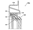
- FIG. 1 is a schematic cross-sectional view of a water pump 10 for an automobile.
- the water pump 10 includes a rotating shaft 21 and a housing 30 having a shaft hole through which the rotating shaft 21 is inserted.
- a bearing 22 for smooth rotation of the rotating shaft 21 is attached to the rotating shaft 21.
- a pulley 23 to which a rotational driving force is applied by a belt (not shown) or the like is attached to one end side of the rotating shaft 21, and an impeller 24 for pressure-feeding cooling water (LLC) is attached to the other end side.
- LLC pressure-feeding cooling water
- the sealing device 100 is connected to the rotating shaft 21. It arrange
- the fluid to be sealed is cooling water.
- FIG.2 and FIG.3 are cross-sectional views cut along a plane passing through the center of the rotating shaft 21, FIG. 2 shows a cross section of the sealing device 100 alone, and FIG. The cross section in the used state is shown.
- FIG. 3B shows the direction of rotation of the rotating shaft (arrow R in the figure) when viewed in the Z direction in FIG.
- the sealing device 100 has a rotationally symmetric shape.
- the sealing device 100 includes a metal cartridge 110, a rubber first seal lip 120, a metal case 130, a synthetic resin second seal lip 140, a metal backup ring 150, and a metal Adapter 160 and grease 170 as a lubricant.
- the cartridge 110 is composed of an annular member and is fitted to the inner peripheral surface of the shaft hole in the housing 30.
- the first seal lip 120 includes a substantially cylindrical fixed portion 121, an inward portion 122 extending inward from the end portion of the fixed portion 121, and a sealing target fluid side (L) from the inner end of the inward portion 122. And a lip portion 123 configured to extend further inward.
- An annular case 130 is fitted inside the fixed portion 121 of the first seal lip 120. As a result, the fixed portion 121 is sandwiched between the outer peripheral surface of the case 130 and the inner peripheral surface of the cartridge 110, whereby the first seal lip 120 is positioned in the radial direction with respect to the cartridge 110.
- the second seal lip 140 is composed of a plate-like fixed portion 141 and a lip portion 142 configured so as to be further directed from the inner tip of the fixed portion 141 to the inner side and the fluid to be sealed (L). Yes.
- An annular backup ring 150 is provided on the side (A) opposite to the fluid to be sealed of the second seal lip 140.
- the fixed portion 141 of the second seal lip 140 is sandwiched between the backup ring 150 and the inward flange portion 131 of the case 130, whereby the second seal lip 140 is fixed to the cartridge 110. It is in a state.
- the annular adapter 160 is provided on the sealing target fluid side (L) of the fixed portion 121 in the first seal lip 120. Thereby, the first seal lip 120 is also positioned relative to the cartridge 110 in the axial direction.
- a grease 170 is filled in a space region formed between the first seal lip 120 and the second seal lip 140 (see FIG. 2).
- the filling amount of the grease 170 is within a space formed between the first seal lip 120 and the second seal lip 140 in a state where the rotary shaft 21 is attached to the sealing device 100 (the state shown in FIG. 3). The amount is set so that the grease 170 is filled.
- the assembly procedure of the sealing device 100 will be described with reference to FIG.
- the fixed portion 141 of the second seal lip 140 is incorporated inside the case 130.
- the backup ring 150 is fitted (see FIG. 4A).
- the left end of the case 130 in the drawing is bent inward (see the arrow in the drawing).
- the first seal lip 120 is assembled to the case 130, the second seal lip 140, and the backup ring 150 which are integrated (see FIG. 4B).
- the integrated unit is pushed in the axial direction along the inner peripheral surface of the cartridge 110, and the fixed portion 121 of the first seal lip 120 is fitted to the inner peripheral surface of the cartridge 110 (FIG. 4C). )reference).
- the adapter 160 is press-fitted into the inner peripheral surface of the cartridge 110.
- grease 170 is filled in a space region formed between the first seal lip 120 and the second seal lip 140.
- the above-described members are integrated into a cartridge. That is, the sealing device 100 including the cartridge 110, the first seal lip 120, the case 130, the second seal lip 140, the backup ring 150, the adapter 160, and the grease 170 can be handled as one component.
- the lip portion 123 of the first seal lip 120 has a first tapered surface 123a whose tip expands toward the sealing target fluid side (L), and a sealing target. It has the structure which has the 2nd taper surface 123b which expands toward the opposite side (A) from the fluid side. An edge portion E is formed between the first tapered surface 123a and the second tapered surface 123b.
- the second tapered surface 123b is provided with a plurality of screw protrusions (which may be screw grooves) 124 that move the grease 170 in the axial direction in accordance with the relative rotation with the rotary shaft 21.
- the plurality of screw protrusions 124 are arranged to move the grease 170 toward the side (A) opposite to the fluid to be sealed. That is, as the rotating shaft 21 rotates (see FIG. 3B), the lip portion 123 slides with respect to the surface of the rotating shaft 21, and the grease 170 of the lip portion 123 is caused by the screw pump effect of the screw protrusion 124. It moves to the side (A) opposite to the sealing target fluid side from the edge portion E at the tip (see arrow Y in FIG. 3).
- the screw protrusion 124 is provided from the opposite side (A) to the sealing target fluid side on the second tapered surface 123b to a position reaching the edge portion E at the tip of the lip portion 123. Therefore, the function (screw pump function) of moving the grease 170 to the side (A) opposite to the fluid to be sealed can be exhibited from the initial stage where the screw protrusion 124 is not worn by sliding.
- the screw 170 (or screw groove) 124 causes the grease 170 to be on the side (A) opposite to the fluid to be sealed side of the lip portion 123 of the first seal lip 120.
- the function to move can be demonstrated. Therefore, it can suppress that the grease 170 leaks to the sealing object fluid side (L).
- the state in which the grease 170 is filled between the first seal lip 120 and the second seal lip 140 can be stably maintained, and the slidability of the first seal lip 120 can be maintained over a long period of time. Can be made. Accordingly, the generation of abnormal noise (squeal) can be suppressed, and the durability life of the sealing device 100 can be improved by reducing sliding wear.
- the cooling water (LLC) that is the fluid to be sealed is opposite to the fluid to be sealed. Leaking to the side (A) can be effectively suppressed.
- the provision of the screw protrusion (or screw groove) 124 that exhibits the function of moving the fluid on the side (A) opposite to the fluid to be sealed does not promote the leakage of cooling water. .
- FIG. 5 shows a second embodiment of the present invention.
- a modified example of the cartridge in the first embodiment will be described. Since other configurations and operations are the same as those in the first embodiment, the same components are denoted by the same reference numerals and description thereof is omitted.
- the cartridge 110a is provided with an S-shaped section so as to have elasticity in the radial direction without deteriorating the mounting property even for a large annular gap. , So as to sufficiently exhibit the sealing performance. Since the configuration other than the cartridge 110a is as described in the first embodiment, the description thereof is omitted.
- the sealing device As an application example of the sealing device, a case where the sealing device is used in a water pump 10 for an automobile has been described as an example. It is applicable to various devices that need to be performed.
- the present invention can be suitably used as a sealing device or a sealing structure for a shaft seal in a device for home appliances or an industrial water pump with a small load.
Landscapes
- Engineering & Computer Science (AREA)
- General Engineering & Computer Science (AREA)
- Mechanical Engineering (AREA)
- Physics & Mathematics (AREA)
- Fluid Mechanics (AREA)
- Sealing With Elastic Sealing Lips (AREA)
- Structures Of Non-Positive Displacement Pumps (AREA)
- Sealing Devices (AREA)
Abstract
Priority Applications (4)
| Application Number | Priority Date | Filing Date | Title |
|---|---|---|---|
| US13/884,845 US20130228978A1 (en) | 2011-03-31 | 2012-02-29 | Sealing device and sealing structure |
| JP2013507294A JP5839509B2 (ja) | 2011-03-31 | 2012-02-29 | 密封装置及び密封構造 |
| CN201280003921.2A CN103238012B (zh) | 2011-03-31 | 2012-02-29 | 密封装置和密封结构 |
| EP12765069.5A EP2693089A4 (fr) | 2011-03-31 | 2012-02-29 | Dispositif d'étanchéité et structure d'étanchéité |
Applications Claiming Priority (2)
| Application Number | Priority Date | Filing Date | Title |
|---|---|---|---|
| JP2011-078099 | 2011-03-31 | ||
| JP2011078099 | 2011-03-31 |
Publications (1)
| Publication Number | Publication Date |
|---|---|
| WO2012132731A1 true WO2012132731A1 (fr) | 2012-10-04 |
Family
ID=46930478
Family Applications (1)
| Application Number | Title | Priority Date | Filing Date |
|---|---|---|---|
| PCT/JP2012/055087 WO2012132731A1 (fr) | 2011-03-31 | 2012-02-29 | Dispositif d'étanchéité et structure d'étanchéité |
Country Status (5)
| Country | Link |
|---|---|
| US (1) | US20130228978A1 (fr) |
| EP (1) | EP2693089A4 (fr) |
| JP (1) | JP5839509B2 (fr) |
| CN (1) | CN103238012B (fr) |
| WO (1) | WO2012132731A1 (fr) |
Cited By (1)
| Publication number | Priority date | Publication date | Assignee | Title |
|---|---|---|---|---|
| JP2015017688A (ja) * | 2013-07-12 | 2015-01-29 | Nok株式会社 | 密封装置 |
Families Citing this family (5)
| Publication number | Priority date | Publication date | Assignee | Title |
|---|---|---|---|---|
| EP3171057A4 (fr) * | 2014-07-17 | 2018-04-11 | Eagle Industry Co., Ltd. | Dispositif d'étanchéité |
| CN104454629A (zh) * | 2014-12-10 | 2015-03-25 | 襄阳五二五泵业有限公司 | 一种煤化工泵用单向密封环 |
| WO2016108591A1 (fr) * | 2014-12-29 | 2016-07-07 | 씰링크 주식회사 | Dispositif d'étanchéité pour arbre d'entraînement |
| DE102017116535A1 (de) * | 2017-07-21 | 2019-01-24 | Nidec Gpm Gmbh | Dichtungsvorrichtung mit Kavitäten |
| EP3767138A4 (fr) * | 2018-03-15 | 2022-01-19 | Eagle Industry Co., Ltd. | Dispositif d'étanchéité |
Citations (6)
| Publication number | Priority date | Publication date | Assignee | Title |
|---|---|---|---|---|
| JPS4917722Y1 (fr) * | 1973-05-02 | 1974-05-09 | ||
| JPH1073165A (ja) | 1996-06-26 | 1998-03-17 | Nok Corp | 密封装置 |
| JP2000009233A (ja) * | 1998-06-19 | 2000-01-11 | Nok Corp | 密封装置 |
| JP2000110946A (ja) * | 1998-10-06 | 2000-04-18 | Koyo Sealing Techno Co Ltd | 密封装置 |
| JP2001074143A (ja) * | 1999-09-03 | 2001-03-23 | Eagle Ind Co Ltd | リップ型シール |
| JP2009052705A (ja) * | 2007-08-29 | 2009-03-12 | Nok Corp | オイルシール |
Family Cites Families (22)
| Publication number | Priority date | Publication date | Assignee | Title |
|---|---|---|---|---|
| US3633927A (en) * | 1970-02-11 | 1972-01-11 | Federal Mogul Corp | Molded-lip hydrodynamic shaft seal |
| US3785660A (en) * | 1970-10-15 | 1974-01-15 | Republic Ind Corp | Seal |
| US3913925A (en) * | 1973-11-28 | 1975-10-21 | Borg Warner | Positive lubrication hydrodynamic lip seal |
| US4288083A (en) * | 1980-02-07 | 1981-09-08 | International Packings Corporation | Hydrodynamic shaft seal |
| US4616836A (en) * | 1983-04-13 | 1986-10-14 | Chicago Rawhide Mfg. Co. | Reverse lip positive venting seal |
| US4522411A (en) * | 1984-10-01 | 1985-06-11 | Chicago Rawhide Mfg. Co. | Fluid seals with self-venting auxiliary lips |
| US6182975B1 (en) * | 1993-06-04 | 2001-02-06 | Nok Corporation | Sealing device having an annular space between sealing lips |
| JP3150861B2 (ja) * | 1994-12-15 | 2001-03-26 | エヌオーケー株式会社 | 往復動用密封装置 |
| JPH11270697A (ja) * | 1998-03-23 | 1999-10-05 | Nok Corp | オイルシール |
| JP3875824B2 (ja) * | 2000-03-17 | 2007-01-31 | イーグル工業株式会社 | リップ型シール |
| JP2001317635A (ja) * | 2000-05-02 | 2001-11-16 | Toyota Industries Corp | リップ型シール |
| JP2003120823A (ja) * | 2001-10-19 | 2003-04-23 | Eagle Ind Co Ltd | シール装置 |
| JP2005172061A (ja) * | 2003-12-09 | 2005-06-30 | Nok Corp | 密封装置 |
| KR101239771B1 (ko) * | 2005-06-21 | 2013-03-06 | 엔오케이 가부시키가이샤 | 오일시일 및 그 제조방법 |
| CN101331351B (zh) * | 2006-03-08 | 2012-10-03 | 伊格尔工业股份有限公司 | 密封装置 |
| DE102006025799B4 (de) * | 2006-06-02 | 2017-11-23 | Ab Skf | Dichtelement |
| WO2009017022A1 (fr) * | 2007-08-02 | 2009-02-05 | Eagle Industry Co., Ltd. | Dispositif d'étanchéité |
| JP3137481U (ja) * | 2007-09-14 | 2007-11-22 | イーグル工業株式会社 | リップタイプシールの装着構造 |
| JP2009074602A (ja) * | 2007-09-20 | 2009-04-09 | Nok Corp | オイルシール |
| JP4875597B2 (ja) * | 2007-11-28 | 2012-02-15 | イーグル工業株式会社 | リップタイプシール |
| JP2009257421A (ja) * | 2008-04-15 | 2009-11-05 | Toyota Industries Corp | 流体機械の軸封構造 |
| CN101842622B (zh) * | 2008-11-27 | 2014-01-15 | 伊格尔工业股份有限公司 | 唇式密封件 |
-
2012
- 2012-02-29 WO PCT/JP2012/055087 patent/WO2012132731A1/fr active Application Filing
- 2012-02-29 CN CN201280003921.2A patent/CN103238012B/zh not_active Expired - Fee Related
- 2012-02-29 JP JP2013507294A patent/JP5839509B2/ja not_active Expired - Fee Related
- 2012-02-29 EP EP12765069.5A patent/EP2693089A4/fr not_active Ceased
- 2012-02-29 US US13/884,845 patent/US20130228978A1/en not_active Abandoned
Patent Citations (6)
| Publication number | Priority date | Publication date | Assignee | Title |
|---|---|---|---|---|
| JPS4917722Y1 (fr) * | 1973-05-02 | 1974-05-09 | ||
| JPH1073165A (ja) | 1996-06-26 | 1998-03-17 | Nok Corp | 密封装置 |
| JP2000009233A (ja) * | 1998-06-19 | 2000-01-11 | Nok Corp | 密封装置 |
| JP2000110946A (ja) * | 1998-10-06 | 2000-04-18 | Koyo Sealing Techno Co Ltd | 密封装置 |
| JP2001074143A (ja) * | 1999-09-03 | 2001-03-23 | Eagle Ind Co Ltd | リップ型シール |
| JP2009052705A (ja) * | 2007-08-29 | 2009-03-12 | Nok Corp | オイルシール |
Non-Patent Citations (1)
| Title |
|---|
| See also references of EP2693089A4 |
Cited By (1)
| Publication number | Priority date | Publication date | Assignee | Title |
|---|---|---|---|---|
| JP2015017688A (ja) * | 2013-07-12 | 2015-01-29 | Nok株式会社 | 密封装置 |
Also Published As
| Publication number | Publication date |
|---|---|
| CN103238012A (zh) | 2013-08-07 |
| EP2693089A1 (fr) | 2014-02-05 |
| EP2693089A4 (fr) | 2015-05-27 |
| JPWO2012132731A1 (ja) | 2014-07-24 |
| US20130228978A1 (en) | 2013-09-05 |
| CN103238012B (zh) | 2016-01-20 |
| JP5839509B2 (ja) | 2016-01-06 |
Similar Documents
| Publication | Publication Date | Title |
|---|---|---|
| JP6374961B2 (ja) | 密封装置 | |
| JP5839509B2 (ja) | 密封装置及び密封構造 | |
| JP2017150674A (ja) | シールリング | |
| WO2009130933A1 (fr) | Dispositif d’étanchéité | |
| JP6000845B2 (ja) | 密封装置 | |
| WO2015198807A1 (fr) | Dispositif d'étanchéité | |
| US20100066030A1 (en) | Hermetic sealing device | |
| US9850955B2 (en) | Outer race rotation bearing | |
| JP2011174570A (ja) | 密封装置 | |
| JPWO2019004141A1 (ja) | 密封装置 | |
| JP5066787B2 (ja) | 密封構造 | |
| JP2012255495A (ja) | シールリング | |
| JP2002235856A (ja) | 密封装置 | |
| JP7163491B2 (ja) | 密封装置 | |
| JP2010060120A (ja) | 密封装置 | |
| JP2021156314A (ja) | 密封装置 | |
| WO2010116932A1 (fr) | Dispositif d'étanchéité | |
| JP2020016291A (ja) | 密封装置 | |
| JP6023502B2 (ja) | 密封装置 | |
| WO2022264255A1 (fr) | Dispositif d'étanchéité | |
| JP6458905B2 (ja) | シールリング | |
| JP6853367B2 (ja) | 密封装置 | |
| JP2010071377A (ja) | 密封装置 | |
| JP6623775B2 (ja) | 密封構造 | |
| JP2017133571A (ja) | 密封装置 |
Legal Events
| Date | Code | Title | Description |
|---|---|---|---|
| 121 | Ep: the epo has been informed by wipo that ep was designated in this application |
Ref document number: 12765069 Country of ref document: EP Kind code of ref document: A1 |
|
| ENP | Entry into the national phase |
Ref document number: 2013507294 Country of ref document: JP Kind code of ref document: A |
|
| WWE | Wipo information: entry into national phase |
Ref document number: 2012765069 Country of ref document: EP |
|
| WWE | Wipo information: entry into national phase |
Ref document number: 13884845 Country of ref document: US |
|
| NENP | Non-entry into the national phase |
Ref country code: DE |