WO2012132390A1 - 炭素質フィルムの製造方法、およびグラファイトフィルムの製造方法、並びにロール状高分子フィルムおよびロール状炭素質フィルム - Google Patents
炭素質フィルムの製造方法、およびグラファイトフィルムの製造方法、並びにロール状高分子フィルムおよびロール状炭素質フィルム Download PDFInfo
- Publication number
- WO2012132390A1 WO2012132390A1 PCT/JP2012/002079 JP2012002079W WO2012132390A1 WO 2012132390 A1 WO2012132390 A1 WO 2012132390A1 JP 2012002079 W JP2012002079 W JP 2012002079W WO 2012132390 A1 WO2012132390 A1 WO 2012132390A1
- Authority
- WO
- WIPO (PCT)
- Prior art keywords
- film
- polymer film
- roll
- gap
- polymer
- Prior art date
- Legal status (The legal status is an assumption and is not a legal conclusion. Google has not performed a legal analysis and makes no representation as to the accuracy of the status listed.)
- Ceased
Links
Images




Classifications
-
- C—CHEMISTRY; METALLURGY
- C01—INORGANIC CHEMISTRY
- C01B—NON-METALLIC ELEMENTS; COMPOUNDS THEREOF; METALLOIDS OR COMPOUNDS THEREOF NOT COVERED BY SUBCLASS C01C
- C01B32/00—Carbon; Compounds thereof
-
- C—CHEMISTRY; METALLURGY
- C01—INORGANIC CHEMISTRY
- C01B—NON-METALLIC ELEMENTS; COMPOUNDS THEREOF; METALLOIDS OR COMPOUNDS THEREOF NOT COVERED BY SUBCLASS C01C
- C01B32/00—Carbon; Compounds thereof
- C01B32/20—Graphite
- C01B32/21—After-treatment
- C01B32/22—Intercalation
-
- B—PERFORMING OPERATIONS; TRANSPORTING
- B65—CONVEYING; PACKING; STORING; HANDLING THIN OR FILAMENTARY MATERIAL
- B65D—CONTAINERS FOR STORAGE OR TRANSPORT OF ARTICLES OR MATERIALS, e.g. BAGS, BARRELS, BOTTLES, BOXES, CANS, CARTONS, CRATES, DRUMS, JARS, TANKS, HOPPERS, FORWARDING CONTAINERS; ACCESSORIES, CLOSURES, OR FITTINGS THEREFOR; PACKAGING ELEMENTS; PACKAGES
- B65D85/00—Containers, packaging elements or packages, specially adapted for particular articles or materials
- B65D85/67—Containers, packaging elements or packages, specially adapted for particular articles or materials for web or tape-like material
- B65D85/671—Containers, packaging elements or packages, specially adapted for particular articles or materials for web or tape-like material wound in flat spiral form
-
- C—CHEMISTRY; METALLURGY
- C01—INORGANIC CHEMISTRY
- C01B—NON-METALLIC ELEMENTS; COMPOUNDS THEREOF; METALLOIDS OR COMPOUNDS THEREOF NOT COVERED BY SUBCLASS C01C
- C01B32/00—Carbon; Compounds thereof
- C01B32/05—Preparation or purification of carbon not covered by groups C01B32/15, C01B32/20, C01B32/25, C01B32/30
-
- C—CHEMISTRY; METALLURGY
- C01—INORGANIC CHEMISTRY
- C01B—NON-METALLIC ELEMENTS; COMPOUNDS THEREOF; METALLOIDS OR COMPOUNDS THEREOF NOT COVERED BY SUBCLASS C01C
- C01B32/00—Carbon; Compounds thereof
- C01B32/20—Graphite
- C01B32/205—Preparation
-
- C—CHEMISTRY; METALLURGY
- C08—ORGANIC MACROMOLECULAR COMPOUNDS; THEIR PREPARATION OR CHEMICAL WORKING-UP; COMPOSITIONS BASED THEREON
- C08G—MACROMOLECULAR COMPOUNDS OBTAINED OTHERWISE THAN BY REACTIONS ONLY INVOLVING UNSATURATED CARBON-TO-CARBON BONDS
- C08G73/00—Macromolecular compounds obtained by reactions forming a linkage containing nitrogen with or without oxygen or carbon in the main chain of the macromolecule, not provided for in groups C08G12/00 - C08G71/00
- C08G73/06—Polycondensates having nitrogen-containing heterocyclic rings in the main chain of the macromolecule
- C08G73/10—Polyimides; Polyester-imides; Polyamide-imides; Polyamide acids or similar polyimide precursors
-
- Y—GENERAL TAGGING OF NEW TECHNOLOGICAL DEVELOPMENTS; GENERAL TAGGING OF CROSS-SECTIONAL TECHNOLOGIES SPANNING OVER SEVERAL SECTIONS OF THE IPC; TECHNICAL SUBJECTS COVERED BY FORMER USPC CROSS-REFERENCE ART COLLECTIONS [XRACs] AND DIGESTS
- Y10—TECHNICAL SUBJECTS COVERED BY FORMER USPC
- Y10T—TECHNICAL SUBJECTS COVERED BY FORMER US CLASSIFICATION
- Y10T428/00—Stock material or miscellaneous articles
- Y10T428/24—Structurally defined web or sheet [e.g., overall dimension, etc.]
- Y10T428/24744—Longitudinal or transverse tubular cavity or cell
Definitions
- the present invention relates to a method for producing a long (roll-shaped) carbonaceous film by polymer pyrolysis.
- it is related with the process of manufacturing the elongate carbonaceous film which is an intermediate
- Graphite film is a material with excellent properties such as high thermal conductivity, and is widely used for electronic parts.
- Examples of a generally available method for producing a highly heat conductive graphite film include an expanding method in which expanded graphite is rolled into a sheet and a polymer pyrolysis method.
- a polymer film is wound around cylindrical graphitic carbon, and three POD films with a width of 180 mm and a thickness of 50 ⁇ m are wound around a graphite carbon cylinder with an outer diameter of 68 mm, an inner diameter of 64 mm, and a length of 200 mm.
- the manufacturing method of the graphite film heated at 1800 degreeC or more in a vacuum is disclosed, and a elongate graphite film is obtained.
- Patent Document 1 has a problem in that a wave is generated at the end of the finished roll-like carbonaceous film in the carbonization process, which is the previous stage of the carbonaceous film according to the polymer pyrolysis method. It was.
- the generated decomposition gas when the number of windings is increased, it is difficult for the generated decomposition gas to be discharged from between the films, so when cooled, it adheres between the films and acts like an adhesive. Fusion has occurred in the quality film.
- an object of the present invention is to obtain a carbonaceous film in which fusion is suppressed when a long carbonaceous film is produced.
- the fusion of the carbonaceous film occurs when the decomposition gas generated during carbonization decomposition stays between the films and adheres when cooled and acts like an adhesive.
- the obtained carbonaceous film shrinks at the time of carbonization decomposition, and therefore has a size of about 80% of the polymer film as a raw material.
- the shrinkage at the time of carbonization decomposition causes the films to be in a state of being pressed against each other, so that the decomposition gas generated at the time of carbonization decomposition does not escape from between the films, and fusion occurs. Will occur.
- the present invention relates to a method for producing a carbonaceous film through a heat treatment step in a state in which a polymer film is wound into a roll, and the roll polymer is used at a temperature lower than the thermal decomposition start temperature of the polymer film.
- the relationship (Ts / Tf) calculated by dividing the thickness (Ts) of the gap between adjacent polymer films by the thickness (Tf) of the polymer film is 0.16 or more and 1.50 or less, calculated for the entire film.
- a method for producing a carbonaceous film characterized by performing a heat treatment after forming a roll-shaped polymer film having a gap between the polymer films satisfying (Claim 1), The gap between the adjacent polymer films is formed by winding up the interleaving paper at the same time when winding the polymer film in a roll shape, and then removing the interleaving paper.
- the method for producing a carbonaceous film according to Item 1 (Claim 2), 2.
- a manufacturing method (claim 3); 2.
- the present invention relates to a quality film manufacturing method (claim 4).
- the present invention relates to a method for producing a graphite film, characterized in that the carbonaceous film according to any one of claims 1 to 4 is heat-treated to a temperature of 2400 ° C or higher (claim 5).
- the thickness (Ts) of the clearance gap between the said adjacent polymer films calculated about the whole roll-shaped polymer film is said polymer.
- the present invention relates to a roll-like polymer film characterized by having a gap between polymer films satisfying a relationship of 0.16 or more and 1.50 or less (Ts / Tf) divided by film thickness (Tf) (claims) 7).
- the present invention relates to a roll-like carbonaceous film characterized by having a gap between carbonaceous films satisfying a relationship of 0.16 or more and 1.50 or less (Ts / Tf) divided by the thickness (Tf) of the film (claims) 8).
- an appropriate gap can be stably provided between the films of the polymer film wound in a roll shape in the carbonization step, so that the carbonization gas is easily discharged from between the films. It is possible to suppress fusion of the obtained roll-like carbonaceous film and roll-like graphite film.
- the present invention relates to a method for producing a carbonaceous film through a heat treatment step in a state in which a polymer film is wound into a roll, and the roll polymer is used at a temperature lower than the thermal decomposition start temperature of the polymer film.
- the relationship (Ts / Tf) calculated by dividing the thickness (Ts) of the gap between adjacent polymer films by the thickness (Tf) of the polymer film is 0.16 or more and 1.50 or less, calculated for the entire film.
- the adjacent polymer film refers to a polymer film that exists around the periphery (that is, inside or outside) when an arbitrary portion of a roll-shaped polymer film is specified.
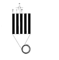
- FIG. the polymer film 10 and the polymer film 11, or the polymer films 11 and 12 are adjacent polymer films.
- the roll shape means a state in which the polymer film is wound, and there is no limitation on the shape, and examples thereof include a perfect circle, an ellipse, and a quadrangle.
- the roll-shaped polymer film refers to a polymer film wound in a roll shape, and a combination of a core and a polymer film wound in a roll shape when a core is present. Note that a gap (space) may be included inside the roll-shaped polymer film.
- the fusion of the carbonaceous film occurs when a decomposition gas generated during carbonization decomposition stays between the films and adheres when cooled and acts like an adhesive. Moreover, since the obtained carbonaceous film shrinks at the time of carbonization decomposition, it becomes about 80% of the size of the polymer film as a raw material. When the polymer film is wound in a roll shape, the shrinkage at the time of carbonization decomposition causes the films to be in a state of being pressed against each other, so that the decomposition gas generated at the time of carbonization decomposition does not escape from between the films, and fusion occurs. Will occur. Therefore, by providing a gap between the films, the compressed state between the polymer films due to shrinkage during carbonization decomposition can be relaxed, and fusion can be improved.
- the thermal decomposition start temperature of the polymer film is defined as a temperature at which a weight loss of 1.0% with respect to the weight of the initial polymer film occurs when the polymer film is heat-treated.
- the sample amount is 10 mg under a nitrogen atmosphere (200 mL / min) at room temperature (23 C.) to 1000 ° C. at a rate of temperature increase of 10 ° C./min and a weight loss of 1.0% occurs.
- the thermal decomposition starting temperature is 500 ° C.
- the measurement of the thermal decomposition start temperature was carried out according to the above definition.
- the gap (Ts / Tf) obtained by dividing the gap (Ts) of the gap between adjacent polymer films by the thickness (Tf) of the polymer film is 0 for the entire roll polymer film. .16 or more. Preferably it is 0.20 or more, More preferably, it is 0.22 or more, More preferably, it is 0.25 or more, More preferably, it is 0.30 or more. Especially, it is preferably 0.33 or more, more preferably 0.5 or more, and further preferably 0.6 or more. There is no particular limitation on the upper limit of Ts / Tf.
- Ts / Tf is 0.16 to 1.5, preferably 0.33 to 1.5
- the undulation of the carbonaceous film can be suppressed.
- the wavyness of the carbonaceous film occurs when the polymer film has a high degree of freedom during shrinkage during carbonization decomposition, and the surface of the carbonaceous film is uneven, as seen from the end of the roll. Even in the case, it is in a wavy state. That is, in order to suppress undulations, it is effective to limit the gap between the films to some extent, and for suppressing the undulations of the carbonaceous film, preferably 1.5 or less, more preferably 1.0 or less. More preferably, it is 0.9 or less.
- (Ts / Tf) is 0.16 or more, preferably (Ts / Tf) is 0.33 or more, fusion can be improved, and if (Ts / Tf) is 1.5 or less, Waves of the carbonaceous film can be suppressed.
- Ts / Tf described above is a value obtained for the entire roll-shaped polymer film.
- the outermost end refers to the outer peripheral end of the roll-shaped polymer film located farthest from the center of the roll-shaped polymer film.
- the end surface (side surface) of a roll-shaped polymer film is illustrated with the perfect circle, it is not limited to this.
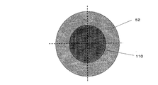
- both are on a straight line passing through the center of the roll-shaped polymer film 52 and the outermost end of the roll-shaped polymer film.
- the average value of the line segment and the line segment on a straight line perpendicular to the line segment was used.
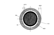
- Ts / Tf was specified by the following method. While applying tension to the core 110 disposed on the inner peripheral side of the roll-shaped polymer film 52 with a tension of 10 N / m or more, the polymer film was wound from the inside so as not to form a gap between the polymer films. (FIG. 8).
- the winding thickness 610 (A) of the polymer film 51 wound around the core is wound every 10 turns of the roll-shaped polymer film 52 which has begun to be wound from the inside while the polymer film is wound around the core in this way.
- the winding thickness 600 (B) of the roll-shaped polymer film of the outer peripheral side after winding around a core was measured.
- the thickness was measured using a calibrated caliper, and measured at the portion in contact with the polymer film so as not to apply pressure to the polymer film.
- the thickness of the roll-shaped polymer film is measured at four points passing through the center of the roll-shaped polymer film 52 and intersecting with the roll-shaped polymer film 52, and the average value of the thickness is measured. The thickness was taken.
- the position of 50% from the inner periphery of the roll-shaped polymer film can be specified, and the formation ratio of the gap at that time can also be specified.
- the gap between the polymer films is preferably provided in a portion of 30% or more, more preferably 50% or more, and further preferably 75% or more of the number of turns of the polymer film.
- the gap between the polymer films It is particularly preferable to form the gap between the polymer films near the inner periphery.
- the shrinkage at the time of carbonization decomposition tends to shrink toward the inside, so that the compression between the polymer films appears particularly in the vicinity of the inner periphery. Therefore, fusion is likely to occur near the inner periphery. Therefore, in the case where gaps having the same cross-sectional area are formed, it is preferable to form gaps near the inner periphery because the effect of mitigating fusion becomes greater.
- the gap may be formed near the outer periphery or may not be formed. However, since it becomes easier to relax the fusion, it is desirable that it be formed not only in the vicinity of the inner periphery but also in the vicinity of the outer periphery.
- the gaps between the polymer films need to be formed before the thermal decomposition start temperature is first reached in the heat treatment. By forming a gap before the start of thermal decomposition, shrinkage during carbonization decomposition can be relaxed and fusion can be suppressed.
- the gap between the polymer films may be formed before the polymer film is set in the furnace or may be formed during the heat treatment step.
- Method for forming gaps between polymer films As a method of forming the gap, (1) a method of loosening during the heat treatment step while reducing the pressure, and (2) a method of winding the interleaving paper simultaneously when winding the polymer film in a roll shape, and then extracting the interleaving paper (3) A method of rewinding a polymer film wound around a core in the reverse direction of the winding direction, and the like.
- the air entrained at the time of winding the polymer film or the moisture absorbed by the polymer film expands, and the winding can be loosened to form a gap. .
- the temperature range in which the pressure is reduced is preferably a temperature range before the carbonization of the polymer film starts, specifically, preferably room temperature to 500 ° C., more preferably 100 ° C. to 450 ° C., and further preferably May include 300 ° C. to 450 ° C. in the reduced pressure region.
- a region above the temperature at which carbonization decomposition starts it is possible to improve the fusion by adopting a structure in which the gas in the furnace can be discharged while introducing an inert gas such as nitrogen or argon.
- Examples of methods for controlling the size of the gap include a method for controlling the amount of air entrained and the amount of moisture absorption, and a method for installing an outer cylinder that can regulate the looseness of the polymer film on the outside of the polymer film roll. It is done.
- the size of the gap becomes the thickness of the interleaving paper, so that the size of the gap can be easily controlled to an arbitrary size. Therefore, for example, the gap near the inner periphery where fusion is more likely to occur can be made larger than the outer periphery, and fusion can be more effectively suppressed. In addition, since the gap can be formed stably, it is possible to suppress variations in the occurrence of fusion. Furthermore, since there is no unevenness in the size of the gaps formed between the layers, the shrinkage force during carbonization decomposition is evenly transmitted to the entire polymer film, and the effect of suppressing undulation is great. Note that the slip sheet may be continuous or discontinuous. For example, it is possible to insert an interleaving paper partially to form an arbitrary gap.
- Timing to remove the slip is not particularly limited as long as it is extracted below the thermal decomposition start temperature of the polymer film, but it can also be extracted immediately after the polymer film and interleaf are wound up at the same time. It may be extracted inside. However, considering the ease of extracting the slip sheet and the removal of the slip sheet, it is preferable to pull the polymer film before setting it in the heat treatment furnace.
- the type of interleaving paper is not particularly limited, and examples thereof include polymer films, paper, and graphite films.
- the interleaving paper is preferably a film that does not damage the polymer film or tear the interleaving paper itself when the interleaving paper is removed.
- the slipperiness can be improved and the slip sheet can be easily removed by using the slip sheet having a release treatment such as silicone or fluorine based on the surface.
- the component contained in the slip sheet adheres to the polymer film, it is preferable to select a material that does not hinder the carbonization of the polymer film or cause fusing or undulation.
- width of the slip sheet it is preferable to make the width narrower in order to easily remove the slip sheet. Specifically, it is preferably 50 mm or less, more preferably 30 mm or less, and still more preferably 20 mm or less.
- the position where the slip sheet is provided is preferably on the end side of the polymer film.
- the slip sheet By winding the slip sheet on the end side of the polymer film, the slip sheet can be easily removed.
- the interleaving paper can be easily pulled out by winding it so that it protrudes further outward than the end of the polymer film.
- the slip sheet may be provided at one place, or may be provided at two or more places. For example, when a slip is attached to the end of the polymer film, the slip may be provided at both ends of the polymer film, or only one end may be provided.
- the winding condition for winding the polymer film and the slip sheet at the same time is not particularly limited, but it is preferable to set the condition so that the slip sheet is easily removed.
- the winding tension is preferably 80 N / m or less, more preferably 40 N / m or less, and still more preferably 20 N / m or less. Further, by rolling while performing static elimination, the slipperiness between the polymer film and the slip sheet can be improved, and the slip sheet can be easily removed.
- the gap can be formed by winding the polymer film while applying tension to the core and then rewinding the polymer film in the direction opposite to the winding direction of the polymer film.
- the polymer film can be prevented from spreading beyond the inner space of the cylinder, so the size of the gap can also be controlled. is there.
- the carbonaceous film of the present invention is obtained through a carbonization step.
- the carbonization step is a step of preheating the polymer film to a temperature of about 1000 ° C., and is a step of thermally decomposing the polymer film to obtain a carbonaceous film.
- the obtained carbonaceous film has a weight of about 60% of the polymer film and is a glassy film.
- the obtained carbonaceous film can be graphitized in the graphitization step to obtain a graphite film.
- a graphitization process is a process which heats the carbonized film created at the carbonization process to the temperature of 2400 degreeC or more, and graphitizes.
- the carbonization step and the graphitization step may be performed continuously, or the carbonization step may be terminated and then only the graphitization step may be performed alone.
- the heat treatment atmosphere in the carbonization step can be performed in an inert gas or in a vacuum. It is particularly effective to introduce an inert gas at an atmospheric temperature higher than the thermal decomposition start temperature.
- a structure in which the gas in the furnace is discharged outside the furnace while introducing the inert gas is preferable. Above the thermal decomposition start temperature, decomposition gas that causes fusion is generated. Therefore, if an inert gas is introduced at a temperature equal to or higher than the thermal decomposition start temperature, the inert gas enters the gaps between the films produced by the production method of the present invention, and the decomposition gas generated during carbonization decomposition is out of the system. Push out. Furthermore, since the discharged cracked gas is discharged out of the furnace together with the inert gas, the risk of newly causing fusion can be reduced.
- the flow rate of the inert gas to be introduced is not particularly limited, but is preferably 1 L / min or more, more preferably 3 L / min or more, and further preferably 5 L / min or more.
- the obtained carbonaceous film can be graphitized in the graphitization step to obtain a graphite film.
- a graphitization process is a process which heats the carbonized film created at the carbonization process to the temperature of 2400 degreeC or more, and graphitizes.
- the carbonized film is graphitized, and a graphite film having high thermal conductivity can be obtained.
- the thermal conductivity is greatly improved and the size is increased by about 10%.
- the carbonization step and the graphitization step may be performed continuously, or the carbonization step may be terminated and thereafter only the graphitization step may be performed alone.
- the heat treatment atmosphere in the graphitization step can be performed in an inert gas atmosphere or in a vacuum.
- the arrangement method of the carbonaceous film may be horizontal or vertical and may be appropriately selected. Further, the core may be used at the time of graphitization after carbonization, or may be removed.
- the roll-like carbonaceous film obtained in the carbonization step may be subjected to the graphitization step as it is, or after being cut into an appropriate size, it may be stacked as necessary to be subjected to the graphitization step.
- the obtained graphite film can be given excellent flexibility by being subjected to a pressing process.
- a value (Ts / Tf) obtained by dividing the gap thickness (Ts) between the adjacent polymer films by the thickness (Tf) of the polymer film is 0.16 or more (preferably 0.33 or more) and 1.50 or less. It is preferable to use a roll-like polymer film characterized by having a gap between polymer films satisfying the above relationship because a carbonaceous film or a graphite film with suppressed fusion can be obtained.
- the roll-like carbonaceous film is a value (Ts / Tf) obtained by dividing the thickness (Ts) of the gap between adjacent carbonaceous films, calculated for the entire roll-like carbonaceous film, by the thickness (Tf) of the carbonaceous film.
- Ts thickness of the gap between adjacent carbonaceous films
- Tf thickness of the carbonaceous film.
- Ts / Tf of a roll-like carbonaceous film is 0.16 or more (preferably 0.33 or more), it is preferable because a graphite film in which scratches and tears are suppressed can be obtained.
- the preferable range of Ts / Tf of the roll-like carbonaceous film is the same as the preferable range of Ts / Tf of the polymer film described above.
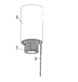
- a container for storing a roll-shaped polymer film with a gap may or may not be provided. However, when providing a container, make sure that the polymer film does not spread too much and the end of the winding does not shift. It is good to leave. By preventing the polymer film from spreading too much and the shift of the winding end, the carbonized film can be prevented from wavy.
- a cylindrical tube or the like is provided outside the polymer film. When a gap is provided between the polymer films, the inner diameter of such a cylinder is the same as the outer diameter of the polymer film provided with the gap, or 5% in consideration of the thermal expansion of the polymer film. It is good to keep it large.
- the container preferably has air permeability, and more preferably has at least a part of a hole for ventilation.
- air permeability By providing the outer cylinder with air permeability, the generated decomposition gas can be easily discharged, so that fusion can be further suppressed.
- the material of the outer cylinder can withstand a continuous use environment at 500 ° C. or higher.
- Materials for containers that satisfy this condition include alumina (Al2O3), zirconia (ZrO2), quartz (SiO2), silicon carbide (SiC), titania (TiO2), magnesia (MgO), silicon nitride (Si3N4), and aluminum nitride (AlN).
- Yttria Y2O3
- mullite 3Al2O3, 2SiO2
- cordierite (2MgO, 2Al2O3, 5SiO2)
- steatite MgO, SiO2
- forsterite 2MgO, SiO2
- carbonization process and graphitization When the process is performed continuously, it is preferably a material that can withstand continuous use at 2000 ° C. or higher, preferably 2800 ° C. or higher, and a composite material C / C composite reinforced with graphite and carbon fiber, extruded product / mold Isotropic graphite materials such as insert molding products and cold isostatic pressing products Conceivable.
- a method of winding a soft material such as graphite film, carbon fiber woven fabric, or felt into a cylindrical shape may be used.
- the shape of the outer cylinder is not particularly limited, but it is highly possible that the inner surface of the outer cylinder is in contact with the polymer film. Moreover, it is preferable that it is a shape near circular.
- the shape of the inner surface may be a quadrangle, and does not necessarily have to be one piece.
- the outer periphery of the polymer film may be surrounded by a plurality of rings, or a plurality of rod-shaped members may be arranged. .
- the roll polymer film may be arranged horizontally or vertically.
- the polymer film provided with a gap has a drooping shape, but by forming a gap as in the present invention, fusion can be improved.
- the width of the polymer film used in the present invention is not particularly limited, but is preferably 150 mm or more, more preferably 250 mm or more, and further preferably 500 mm or more. Usually, when the width of the polymer film is 150 mm or more, fusion is likely to occur, but by using the production method of the present invention, fusion can be effectively suppressed.
- the fused graphite film is “A” when there is no fusion, “B” when there is a fusion of 3 to 9 laps, and the fusion of 10 to 14 laps. “C” is the case where it is present, “D” is the case where 15 to 19 laps of fusion exist, and “E” is the case where there are 20 or more laps.
- the case where the undulation is the roll end shape 200 or less is “A”, more than the roll end shape 200 and less than the roll end shape 210.
- the case was “B”, and the case of more than the roll end shape 210 was “C”.
- Ts / Tf was specified by the following method. While applying tension to the core 110 disposed on the inner peripheral side of the roll-shaped polymer film 52 with a tension of 10 N / m or more, the polymer film was wound from the inside so as not to form a gap between the polymer films. (FIG. 8).
- the winding thickness 610 (A) of the polymer film 51 wound around the core is wound every 10 turns of the roll-shaped polymer film 52 which has begun to be wound from the inside while the polymer film is wound around the core in this way.
- the winding thickness 600 (B) of the roll-shaped polymer film of the outer peripheral side after winding around a core was measured.
- the thickness was measured using a calibrated caliper, and measured at the portion in contact with the polymer film so as not to apply pressure to the polymer film.
- the thickness of the roll-shaped polymer film is measured at four points passing through the center of the roll-shaped polymer film 52 and intersecting with the roll-shaped polymer film 52, and the average value of the thickness is measured. The thickness was taken.
- the position of 50% from the inner periphery of the roll-shaped polymer film can be specified, and the formation ratio of the gap at that time can also be specified.
- a polymer film 50 is a polyimide film (trade name: Apical 75AH film, thickness 75 ⁇ m) manufactured by Kaneka Corporation having a width of 250 mm and a length of 50 m.
- a film (thickness 25 ⁇ m) was prepared, and the polymer film 50 and the interleaf paper were wound around the core 100 having a diameter of 100 mm.
- two interleaving papers were prepared, and the polymer film was wound around both ends of the polymer film at the same time. As shown in FIG.
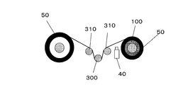
- the winding condition was performed at a tension of 20 N / m and a winding speed of 10 m / min for both the polymer film and the interleaf, while neutralizing the surface on one side of the film with the static eliminating machine 40.
- the tension was detected using the pickup roller 300 in FIG.
- the outermost periphery of the roll-shaped polymer film is fixed with an adhesive tape so that winding does not occur, and the interleaf paper 80 is pulled out from the outer periphery as shown in FIG. Formed.
- the size of the gap immediately after the gap formation was 25 ⁇ m ⁇ 2.0 ⁇ m, and uniform gaps were formed between the layers.
- the roll-shaped polymer film in which the gap was formed was set vertically in the indirect heating furnace together with the core 100 as shown in FIG. 5, and the adhesive tape that fixed the outer periphery of the roll-shaped polymer film was peeled off.
- the ends of the roll-shaped polymer film were set so as not to be displaced.
- Heating is performed by energizing and heating the heater 500 installed outside the roll-shaped polymer film, and the temperature is increased from room temperature to 1000 ° C. at a rate of 1 ° C./min while flowing nitrogen gas at a flow rate of 5 L / min. Warm and carbonize.
- the nitrogen gas is introduced from the introduction hole 65, the exhaust is performed toward the pipe 70.
- Table 1 The results are shown in Table 1.
- Example 2 The same procedure as in Example 1 was performed, except that a PET film (thickness 50 ⁇ m) having a width of 25 mm and a length of 50 m was used as the interleaf paper 80.
- the size of the gap immediately after the gap formation was 50 ⁇ m ⁇ 2.0 ⁇ m, and uniform gaps were formed between the layers. The results are shown in Table 1.
- Example 3 The same procedure as in Example 1 was performed except that a PET film (thickness: 75 ⁇ m) having a width of 25 mm and a length of 50 m was used as the interleaf paper 80.
- the size of the gap immediately after the gap formation was 75 ⁇ m ⁇ 2.0 ⁇ m, and uniform gaps were formed between the layers. The results are shown in Table 1.
- Example 4 The same procedure as in Example 1 was performed except that a polyimide film (trade name: Apical 200AV film, thickness 50 ⁇ m) having a width of 250 mm and a length of 50 m was used as the polymer film 50.
- the size of the gap immediately after the gap formation was 25 ⁇ m ⁇ 2.0 ⁇ m, and uniform gaps were formed between the layers. The results are shown in Table 1.
- Example 5 As the polymer film 50, a polyimide film (trade name: Apical 200AV film, thickness 50 ⁇ m) having a width of 250 mm and a length of 50 m was used, and as the interleaf paper 80, a PET film (width 25 mm, length 50 m) The method was the same as in Example 1 except that a thickness of 37 ⁇ m was used. The size of the gap immediately after the gap formation was 37 ⁇ m ⁇ 2.0 ⁇ m, and uniform gaps were formed between the layers. The results are shown in Table 1.
- Example 6 As the polymer film 50, a polyimide film (trade name: Apical 200AV film, thickness 50 ⁇ m) having a width of 250 mm and a length of 50 m was used, and as the interleaf paper 80, a PET film (width 25 mm, length 50 m) The method was the same as in Example 1 except that a thickness of 50 ⁇ m was used. The size of the gap immediately after the gap formation was 50 ⁇ m ⁇ 2.0 ⁇ m, and uniform gaps were formed between the layers. The results are shown in Table 1.
- Example 7 As the polymer film 50, a polyimide film (trade name: Apical 200AV film, thickness 50 ⁇ m) having a width of 250 mm and a length of 50 m was used, and as the interleaf paper 80, a PET film (width 25 mm, length 50 m) The method was the same as Example 1 except that a thickness of 75 ⁇ m was used. The size of the gap immediately after the gap formation was 75 ⁇ m ⁇ 2.0 ⁇ m, and uniform gaps were formed between the layers. The results are shown in Table 1.
- a Kaneka polyimide film (trade name: Apical 75AH film, thickness 75 ⁇ m) having a width of 250 mm and a length of 50 m is prepared as a polymer film 50, and the polymer film 50 is a core 100 having a diameter of 100 mm.
- the winding condition was performed at a tension of 80 N / m and a winding speed of 10 m / min while the surface of one side of the film was neutralized by the static eliminator 40 as shown in FIG. The tension was detected using the pickup roller 300 in FIG. After winding, the roll-shaped polymer film was set vertically in the indirect heating furnace as shown in FIG.
- Heating is performed by energizing and heating the heater 500 installed outside the roll-shaped polymer film, and the temperature is increased from room temperature to 1000 ° C. at a rate of 1 ° C./min while flowing nitrogen gas at a flow rate of 5 L / min. Warm and carbonize.
- the nitrogen gas is introduced from the introduction hole 65, the exhaust is performed toward the pipe 70.
- Table 1 The results are shown in Table 1.
- Example 1 As compared with Comparative Example 1 in which no gap was formed between the polymer films, it was found that in Examples 1 to 7 in which gaps were formed between the polymer films, the fusion could be greatly improved. Further, when Examples 1 to 7 were compared, as for the size of the gap, in Example 1 where Tf / Ts was 0.33, fusion occurred 10 times, but Tf / Ts was 0.67. In Example 2 and Example 3 in which Tf / Ts is 1.00, no fusion was observed. However, in Example 3 where Tf / Ts was 1.00, some undulations occurred. This is because the size of the gap is slightly large, and a space for deformation during carbonization shrinkage has been provided.
- Example 4 in which the thickness of the polymer film is 50 ⁇ m, the size of the gap and the occurrence of fusion and undulation show similar tendencies, and in Example 4 in which Tf / Ts is 0.50, Fusion occurred 5 times, but no fusion occurred in Examples 5 to 7 where Tf / Ts was larger than 0.50. However, in Example 6 where Tf / Ts was 1.00, some undulations started to occur, and when Tf / Ts increased to 1.50, undulations occurred even more.
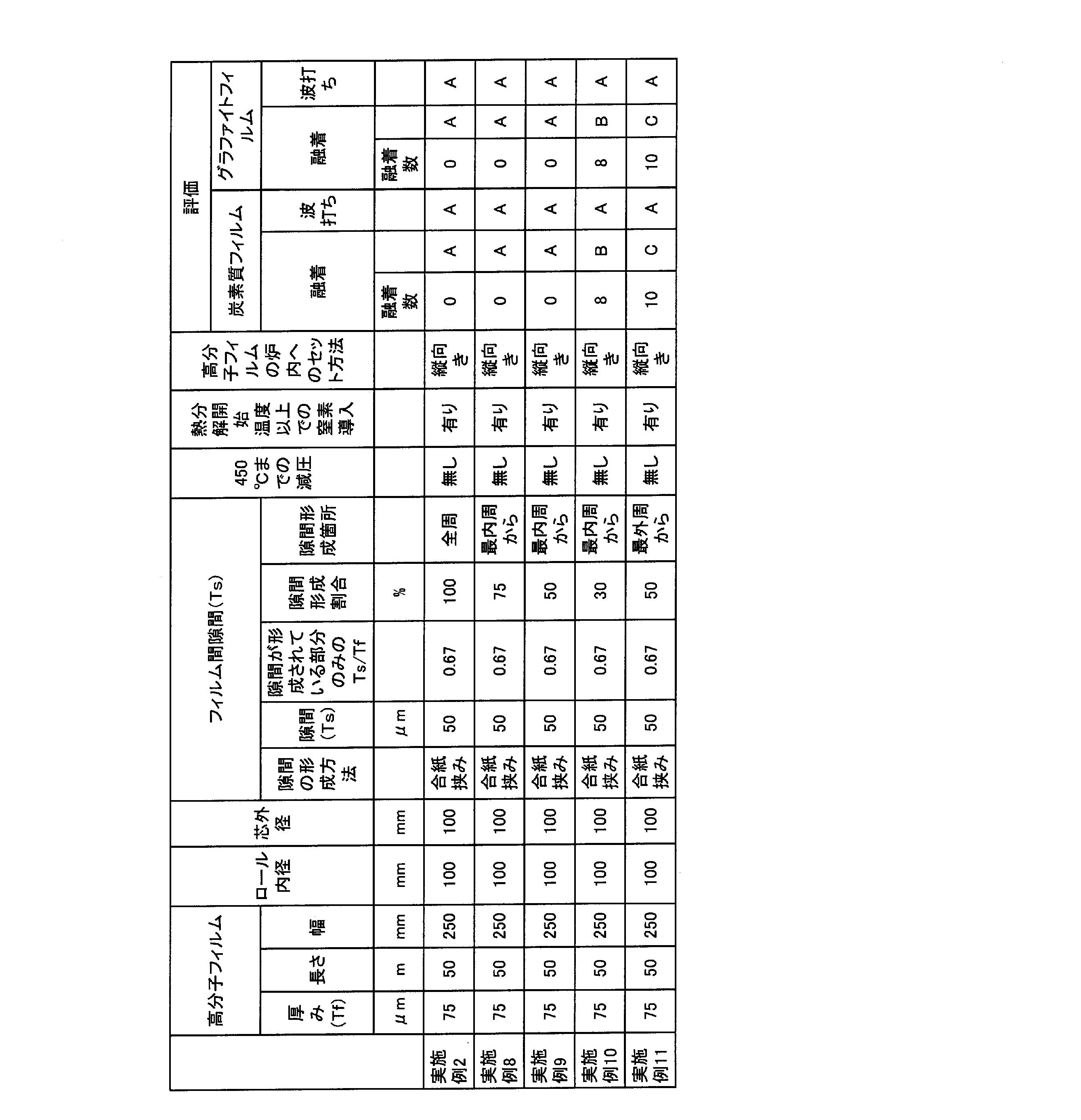
- Example 8 The interleaving paper was simultaneously wound up between the polymer films until it was wound up to 38 m from the beginning of winding, and thereafter the interleaving paper was not used until 50 m. Other than that was carried out similarly to Example 2.
- the size of the gap immediately after the gap formation was 50 ⁇ m ⁇ 2.0 ⁇ m, and uniform gaps were formed between the respective layers of the 75% portion on the inner peripheral side. The results are shown in Table 2.
- the Ts / Tf of the gap forming portion (75% from the innermost circumference) was 0.67, and the Ts / Tf of the entire roll was 0.50.
- Example 9 The interleaf paper was wound up at the same time between the polymer films until it was wound up to 25 m from the beginning of winding, and then the interleaf paper was not used until 50 m. Other than that was carried out similarly to Example 2.
- the size of the gap immediately after the gap formation was 50 ⁇ m ⁇ 2.0 ⁇ m, and uniform gaps were formed between the respective layers on the inner peripheral side 50%.
- the results are shown in Table 2.
- the Ts / Tf of the gap forming portion (50% from the innermost circumference) was 0.67, and the Ts / Tf of the entire roll was 0.33.
- Example 10 The interleaf paper was wound up at the same time between the polymer films until it was wound up by 15 m from the beginning of winding, and then the interleaf paper was not used until 50 m. Other than that was carried out similarly to Example 2.
- the size of the gap immediately after the formation of the gap was 50 ⁇ m ⁇ 2.0 ⁇ m, and uniform gaps were formed between the layers on the inner peripheral side 30%. The results are shown in Table 2.
- the Ts / Tf of the gap forming portion (30% from the innermost circumference) was 0.67, and the Ts / Tf of the entire roll was 0.20.
- Example 11 The interleaf paper was not used until it was wound up to 25 m from the start of winding, and then wound up simultaneously between the polymer films from 25 m to 50 m. Other than that was carried out similarly to Example 2.
- the size of the gap immediately after the gap formation was 50 ⁇ m ⁇ 2.0 ⁇ m, and uniform gaps were formed between the respective layers on the outer peripheral side 50%.
- the results are shown in Table 2.
- the Ts / Tf of the gap forming portion (50% from the outermost periphery) was 0.67, and Ts / Tf of the entire roll was 0.33.
- Example 9 From the results of Example 9 and Example 11, it was found that when the gap is partially provided, the fusion can be improved by providing the gap near the inner periphery. From the results of Example 2 and Examples 8 to 10, the gap formation rate should be 30% or more, and in Examples 2, 8, and 9 where the gap formation rate is 50% or more, fusion occurs. There wasn't.
- Example 12 After filling the furnace with nitrogen gas at room temperature, heat treatment was performed from room temperature to 1000 ° C. without introducing nitrogen gas. Other than that was carried out similarly to Example 2. The size of the gap immediately after the gap formation was 50 ⁇ m ⁇ 2.0 ⁇ m, and uniform gaps were formed between the layers. The results are shown in Table 3.
- Example 13 The pressure is reduced from room temperature to 450 ° C., heat treatment is performed at a furnace pressure of 0.04 kPa (absolute pressure), nitrogen is introduced at 450 ° C., the pressure is returned to atmospheric pressure, and nitrogen gas is introduced at a flow rate of 5 L / min. Heat treatment was performed up to ° C. Other than that was carried out similarly to Example 2. The size of the gap immediately after the gap formation was 50 ⁇ m ⁇ 2.0 ⁇ m, and uniform gaps were formed between the layers. The results are shown in Table 3.
- Example 2 in which heat treatment was performed while introducing nitrogen in a temperature range higher than the thermal decomposition start temperature, no fusion occurred, but heat treatment was performed without introducing nitrogen in a temperature range higher than the thermal decomposition start temperature. In Example 12, a slight fusion occurred. In Example 13, where pressure was reduced in the temperature range up to 450 ° C., which was the temperature range before carbonization, no fusion occurred as in Example 2 where the temperature range was up to 450 ° C. under normal pressure. I understood. If no gap is formed between the polymer films before the heat treatment, the pressure is reduced during the heat treatment process. If there was a gap before the heat treatment process, the air between the films would escape from the gap to the outside of the film, so the gap was hardly too large and carbonization proceeded well. it is conceivable that.
- a Kaneka polyimide film (trade name: Apical 75AH film, thickness 75 ⁇ m) having a width of 250 mm and a length of 50 m is prepared as a polymer film 50, and the polymer film 50 is a core 100 having a diameter of 100 mm.
- the winding condition was performed at a tension of 80 N / m and a winding speed of 10 m / min while the surface of one side of the film was neutralized by the static eliminator 40 as shown in FIG. The tension was detected using the pickup roller 300 in FIG. After winding, the roll-shaped polymer film was set vertically in the indirect heating furnace as shown in FIG.
- Heating is performed by energizing and heating the heater 500 installed outside the roll-shaped polymer film, and heat treatment is performed while reducing the pressure from room temperature to 450 ° C. (furnace pressure 0.04 kPa (absolute pressure)). A gap was provided between them, nitrogen was introduced at 450 ° C., the pressure was returned to atmospheric pressure, and heat treatment was performed up to 1000 ° C. while flowing nitrogen gas at a flow rate of 5 L / min. Here, since the nitrogen gas is introduced from the introduction hole 65, the exhaust is performed toward the pipe 70. The results are shown in Table 4.
- Example 14 As a method of forming a gap between the polymer films, Example 14 in which a temperature range from room temperature to 450 ° C. was heat-treated at a reduced pressure, and the interleaving paper was simultaneously wound between the polymer films, and then the gaps were taken. In Example 2 in which the film was formed, no fusion occurred in any case. However, in the case of Example 14 in which the gap was formed by decompression, some undulation occurred, but no undulation occurred when the gap was formed by inserting and removing the slip sheet. This is considered to be because the method of forming the gap by inserting and removing the slip sheet can form a more uniform and stable gap.
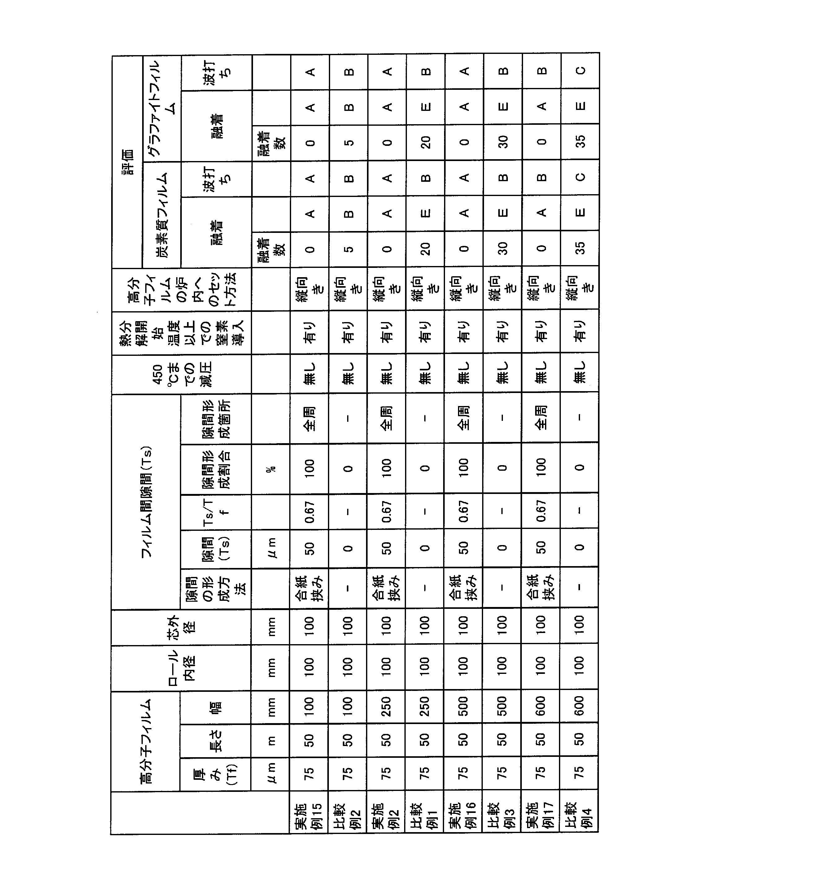
- Example 15 The same procedure as in Example 2 was performed, except that a polyimide film (trade name: Apical 75AH film, thickness 75 ⁇ m) having a width of 100 mm and a length of 50 m was used as the polymer film 50.
- the size of the gap immediately after the gap formation was 50 ⁇ m ⁇ 2.0 ⁇ m, and uniform gaps were formed between the layers. The results are shown in Table 5.
- Example 16 The same procedure as in Example 2 was performed except that a polyimide film (trade name: Apical 75AH film, thickness 75 ⁇ m) having a width of 500 mm and a length of 50 m was used as the polymer film 50.
- the size of the gap immediately after the gap formation was 50 ⁇ m ⁇ 2.0 ⁇ m, and uniform gaps were formed between the layers. The results are shown in Table 5.
- Example 17 The same procedure as in Example 2 was performed, except that a polyimide film (trade name: Apical 75AH film, thickness 75 ⁇ m) having a width of 600 mm and a length of 50 m was used as the polymer film 50.
- the size of the gap immediately after the gap formation was 50 ⁇ m ⁇ 2.0 ⁇ m, and uniform gaps were formed between the layers. The results are shown in Table 5.
- Comparative Example 2 As the polymer film 50, it carried out like the comparative example 1 except having used the polyimide film (Brand name: Apical 75AH film, thickness 75micrometer) of Kaneka company of width 100mm and length 50m. The results are shown in Table 5.
- Comparative Example 3 The same procedure as in Comparative Example 1 was conducted except that a polyimide film (trade name: Apical 75AH film, thickness 75 ⁇ m) having a width of 500 mm and a length of 50 m was used as the polymer film 50. The results are shown in Table 5.
- a polyimide film trade name: Apical 75AH film, thickness 75 ⁇ m
- Table 5 The results are shown in Table 5.
- Comparative Example 4 The same procedure as in Comparative Example 1 was performed except that a polyimide film (trade name: Apical 75AH film, thickness 75 ⁇ m) having a width of 600 mm and a length of 50 m was used as the polymer film 50. The results are shown in Table 5.
- a polyimide film trade name: Apical 75AH film, thickness 75 ⁇ m
- Table 5 The results are shown in Table 5.
- Example 18 The same procedure as in Example 2 was performed except that a polyimide film (trade name: Apical 75AH film, thickness 75 ⁇ m) having a width of 250 mm and a length of 100 m was used as the polymer film 50.
- the size of the gap immediately after the gap formation was 50 ⁇ m ⁇ 2.0 ⁇ m, and uniform gaps were formed between the layers. The results are shown in Table 6.
- Example 19 The same procedure as in Example 3 was conducted except that a polyimide film (trade name: Apical 75AH film, thickness 75 ⁇ m) having a width of 250 mm and a length of 100 m was used as the polymer film 50.
- the size of the gap immediately after the gap formation was 75 ⁇ m ⁇ 2.0 ⁇ m, and uniform gaps were formed between the layers. The results are shown in Table 6.
- Comparative Example 5 The same procedure as in Comparative Example 1 was performed except that a polyimide film (trade name: Apical 75AH film, thickness 75 ⁇ m) having a width of 250 mm and a length of 100 m was used as the polymer film 50. The results are shown in Table 6.
- Example 20 The same procedure as in Example 2 was performed except that the setting method in the indirect heating furnace was set to be horizontal. The size of the gap immediately after the gap formation was 50 ⁇ m ⁇ 2.0 ⁇ m, and uniform gaps were formed between the layers. The results are shown in Table 7.
- Example 21 The same procedure as in Example 2 was performed, except that a polyimide film (thickness: 50 ⁇ m) having a width of 25 mm and a length of 50 m was used as the interleaf paper 80.
- the size of the gap immediately after the gap formation was 50 ⁇ m ⁇ 2.0 ⁇ m, and uniform gaps were formed between the layers. The results are shown in Table 8.
- Example 22 The same procedure as in Example 2 was performed except that a polyethylene (PE) film (thickness 50 ⁇ m) having a width of 25 mm and a length of 50 m was used as the interleaf paper 80.
- the size of the gap immediately after the gap formation was 50 ⁇ m ⁇ 2.0 ⁇ m, and uniform gaps were formed between the layers. The results are shown in Table 8.
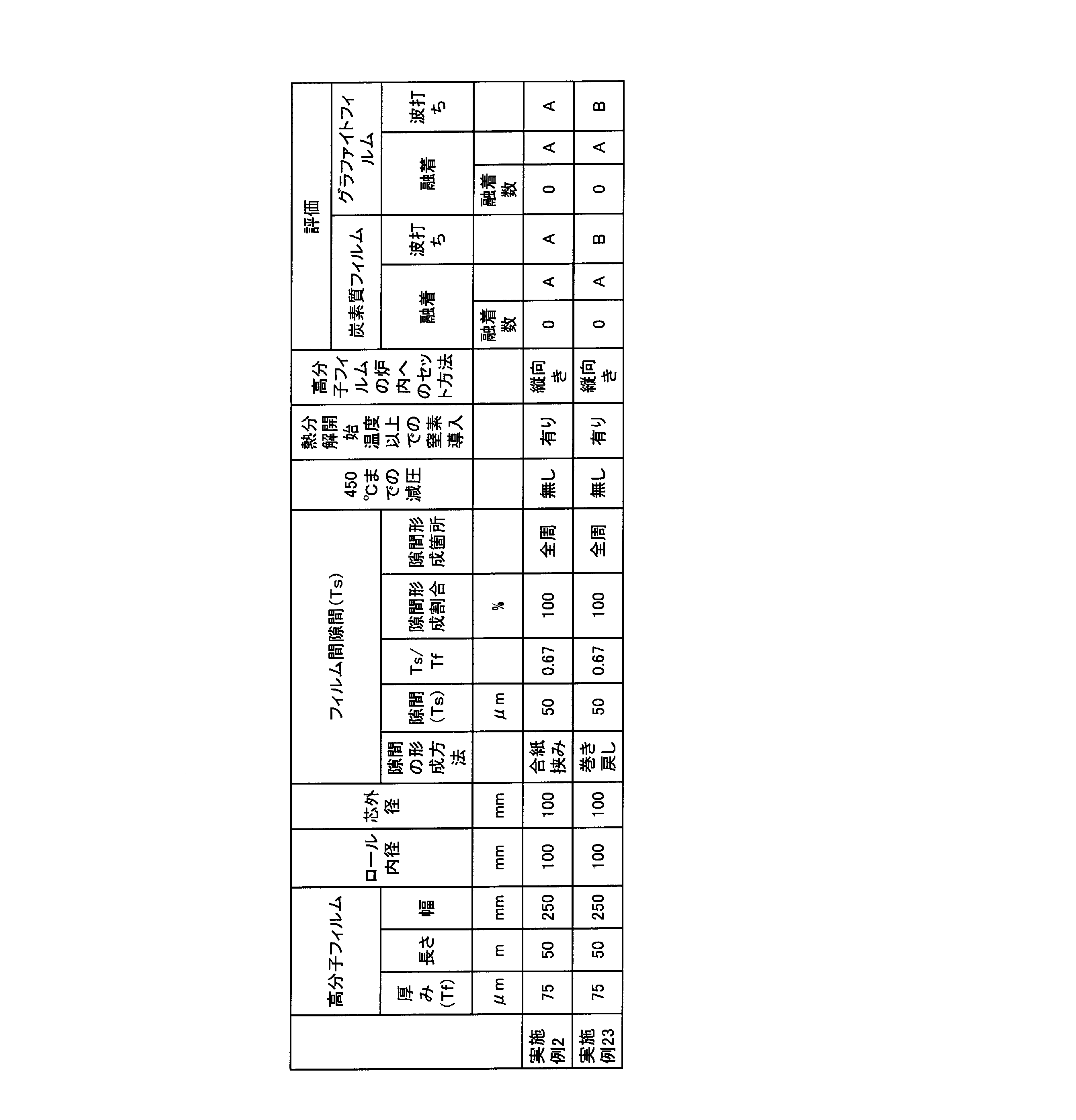
- a Kaneka polyimide film (trade name: Apical 75AH film, thickness 75 ⁇ m) having a width of 250 mm and a length of 50 m is prepared as the polymer film 50, and the polymer film 50 is 100 mm in diameter and 300 mm in length.
- Rewinding was performed at the center of the core 100.
- the winding condition was performed at a tension of 80 N / m and a winding speed of 10 m / min while the surface of one side of the film was neutralized by the static eliminator 40 as shown in FIG. The tension was detected using the pickup roller 300 in FIG. After winding, the roll-shaped polymer film is set vertically with the core 100 as shown in FIG.
- a tube having an inner diameter of 134 mm is set on the outside of the roll-shaped polymer film to reverse the winding direction of the polymer film.
- the film was rewound in the direction of and a gap was formed between the polymer films.
- the size of the gap immediately after the formation of the gap was almost uniformly formed between the respective layers, and was 50 ⁇ m on average.
- the roll-shaped polymer film in which the gap was formed was set vertically in the indirect heating furnace as shown in FIG.
- the ends of the roll-shaped polymer film were set so as not to be displaced.
- Heating is performed by energizing and heating the heater 500 installed outside the roll-shaped polymer film, and the temperature is increased from room temperature to 1000 ° C. at a rate of 1 ° C./min while flowing nitrogen gas at a flow rate of 5 L / min. Warm and carbonize.
- the nitrogen gas is introduced from the introduction hole 65, the exhaust is performed toward the pipe 70.
- Table 9 The results are shown in Table 9.
- Example 23 Even in Example 23 in which a gap was formed in the polymer film by rewinding, carbonization could be performed without fusing as in Example 2 in which a gap was formed using interleaving paper. However, since the size of the gap was slightly nonuniform in each layer, undulation was slightly generated.
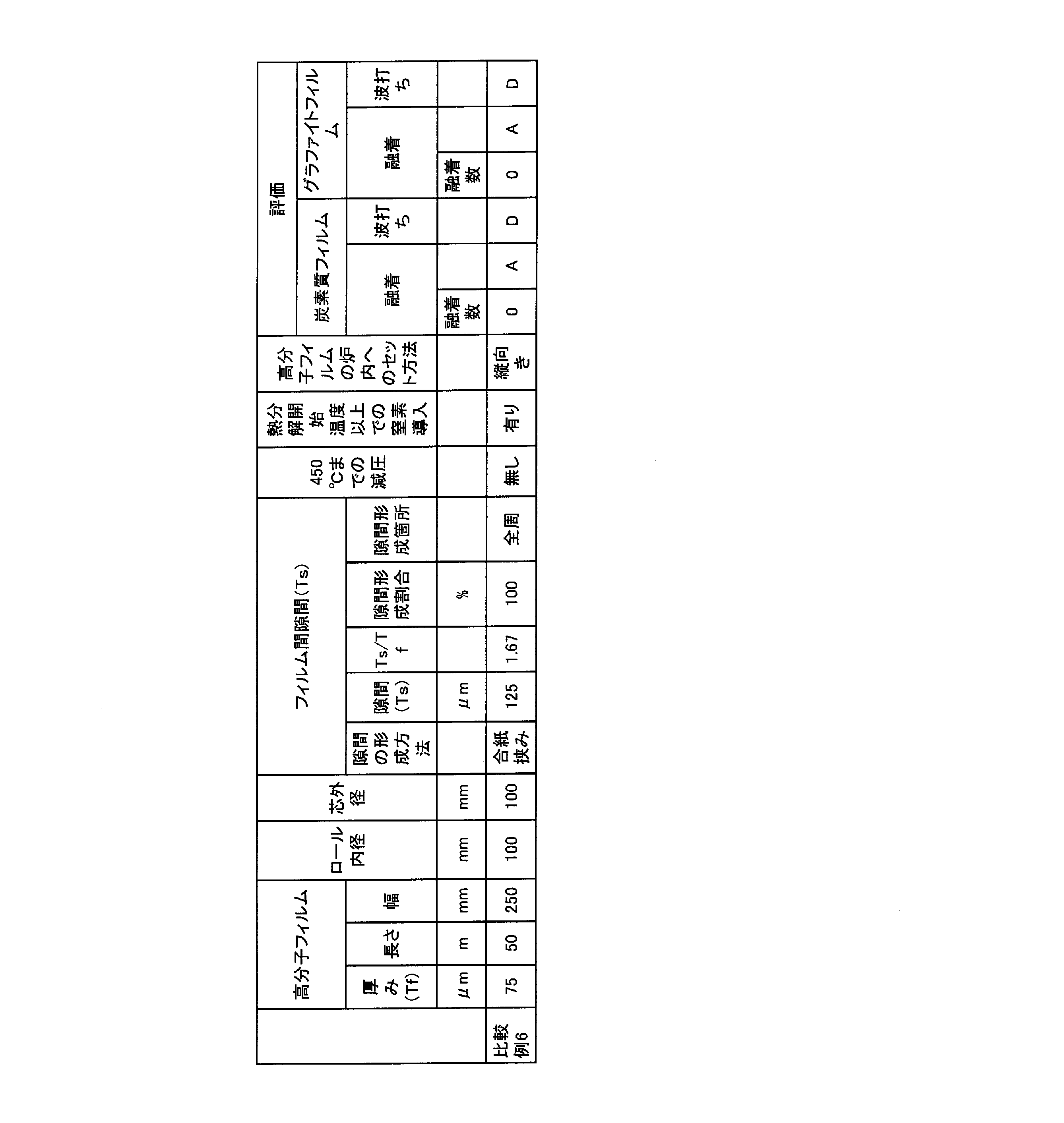
- Example 6 The same procedure as in Example 1 was performed except that a PET film (thickness: 125 ⁇ m) having a width of 25 mm and a length of 50 m was used as the interleaf paper 80.
- the size of the gap immediately after the gap formation was 50 ⁇ m ⁇ 2.0 ⁇ m, and uniform gaps were formed between the layers. The results are shown in Table 10.
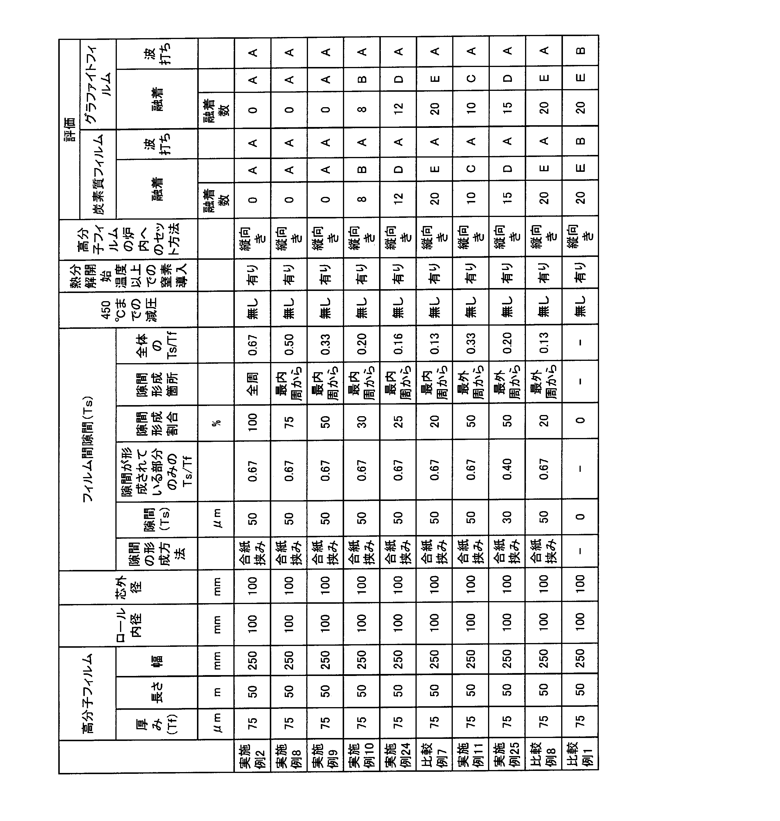
- Example 24 The interleaving paper was simultaneously wound between the polymer films until 12.5 m was wound from the beginning of winding, and thereafter the interleaving paper was not used until 50 m. Other than that was carried out similarly to Example 2.
- the size of the gap immediately after the formation of the gap was 50 ⁇ m ⁇ 2.0 ⁇ m, and uniform gaps were formed between the respective layers on the inner peripheral side 25%. The results are shown in Table 11.
- the Ts / Tf of the gap forming portion (25% from the innermost circumference) was 0.67, and the Ts / Tf of the entire roll was 0.16.
- Example 7 The interleaving paper was simultaneously wound between the polymer films until 10 m was wound from the beginning of winding, and then the interleaving paper was not used until 50 m. Other than that was carried out similarly to Example 2.
- the size of the gap immediately after the formation of the gap was 50 ⁇ m ⁇ 2.0 ⁇ m, and uniform gaps were formed between the respective layers on the inner peripheral side 20%. The results are shown in Table 11.
- the Ts / Tf of the gap forming portion (20% from the innermost circumference) was 0.67, and the Ts / Tf of the entire roll was 0.13.
- Example 25 The interleaf paper is not used until it is wound up to 25 m from the start of winding, and then from 25 m to 50 m, a 25 mm wide and 25 m long PET film (thickness 30 ⁇ m) is used as the interleaf paper. I was winding up at the same time. Other than that was carried out similarly to Example 2. The size of the gap immediately after the gap formation was 30 ⁇ m ⁇ 2.0 ⁇ m, and uniform gaps were formed between the respective layers on the outer peripheral side 50%. The results are shown in Table 11. The Ts / Tf of the gap forming portion (50% from the outermost periphery) was 0.40, and the Ts / Tf of the entire roll was 0.20.
- Example 7 From the results of Examples 2, 8, 9, 10, 24, and Comparative Example 7, it can be seen that the number of fusions increases when the gap formation ratio is reduced. As in Example 24, Ts / Tf of the entire roll is obtained. It can be seen that the fusion can be suppressed when the value is 0.16 or more. On the other hand, from the results of Examples 11 and 25, when the gap is localized on the roll, it can be seen that there is a fusion suppressing effect even when the gap is formed on the outer peripheral side. Further, from the comparison of Examples 11 and 25, even if the gap formation ratio is the same, the Ts / Tf of the portion where the gap is formed is increased from 0.40 to 0.67, so that the Ts / Tf of the entire roll is from 0.20. It can be seen that the effect of suppressing fusion is increased by 0.33.
Landscapes
- Chemical & Material Sciences (AREA)
- Organic Chemistry (AREA)
- Inorganic Chemistry (AREA)
- Life Sciences & Earth Sciences (AREA)
- General Life Sciences & Earth Sciences (AREA)
- Geology (AREA)
- Health & Medical Sciences (AREA)
- Chemical Kinetics & Catalysis (AREA)
- Medicinal Chemistry (AREA)
- Polymers & Plastics (AREA)
- Engineering & Computer Science (AREA)
- Mechanical Engineering (AREA)
- Carbon And Carbon Compounds (AREA)
- Ceramic Products (AREA)
Abstract
Description
前記隣り合う高分子フィルム間の隙間が、該高分子フィルムをロール状に巻く際に合紙を同時に巻き取り、その後、前記合紙を抜き取ることにより形成されたものであることを特徴とする請求項1に記載の炭素質フィルムの製造方法に関する(請求項2)、
前記隣り合う高分子フィルム間の隙間が、芯に巻いた前記高分子フィルムを巻き方向と逆に巻き戻すことにより形成されたものであることを特徴とする請求項1に記載の炭素質フィルムの製造方法に関する(請求項3)、
前記隣り合う高分子フィルム間の隙間が、該高分子フィルムの熱分解開始温度未満の温度において加熱炉内を減圧することによって形成されたものであることを特徴とする請求項1に記載の炭素質フィルムの製造方法に関する(請求項4)、ものである。
隣り合う高分子フィルム間の隙間は、隣り合う高分子フィルム間の隙間(Ts)を高分子フィルムの厚み(Tf)で割った値(Ts/Tf)が、ロール状高分子フィルム全体について、0.16以上である。好ましくは0.20以上、より好ましくは0.22以上、さらに好ましくは0.25以上、さらにより好ましくは0.30以上である。なかでも、好ましくは0.33以上、より好ましくは0.5以上、さらに好ましくは0.6以上である。Ts/Tfの上限値に特に制限はない。
<1>巻芯が存在する場合には、巻芯の外径(Rs)を測定する。(以下、巻芯を芯ともいう。)
<2>ロール状高分子フィルム52の外周端部を動かないように固定した後、ロール状高分子フィルムの内径(Ra)と外径(Rb)を測定する。これらの測定において、図7のように、ロール状高分子フィルム52の中心とロール状高分子フィルム52の最外端を通る直線上の線分と、これに直交する直線上の線分、の平均値を用いた。ここで、最外端とは、ロール状高分子フィルムの中心から最も遠い位置にある当該ロール状高分子フィルムの外周端をいう。なお、図7では、ロール状高分子フィルムの端面(側面)を真円で図示しているが、これに限定されない。

高分子フィルム間の隙間は、好ましくは、高分子フィルムの巻数の30%以上、より好ましくは50%以上、さらに好ましくは75%以上の部分に設けられていると良い。高分子フィルムの巻数の30%以上、より好ましくは50%以上に隙間を設けることで、炭化分解時の高分子フィルム同士の圧迫を緩和することができる。
高分子フィルム間の隙間の形成箇所は、特に内周付近に形成することが好ましい。ロール状高分子フィルムにおいて炭化分解時の収縮は、内側に向かって収縮していく傾向にあるので、高分子フィルム同士の圧迫は特に内周付近で顕著に表れる。そのため、融着も内周付近で発生しやすい。よって、同じ断面積の隙間を形成する場合には、より内周付近に隙間を形成した場合の方が融着を緩和する効果が大きくなるために好ましい。内周付近に隙間が形成されている時には、外周付近には隙間は形成されていてもよいし、形成されていなくともよい。しかし、融着をより緩和しやすくなるので、内周付近に加えて、外周付近にも形成されている方が望ましい。
高分子フィルム間の隙間の形成は、熱処理において最初に熱分解開始温度に達するまでに形成しておくことが必要である。熱分解開始までに隙間を形成しておくことで、炭化分解時の収縮を緩和することができ、融着を抑制することができる。高分子フィルム間の隙間は、高分子フィルムを炉内にセットする以前に形成しておいても、熱処理工程中に形成してもよい。
隙間の形成方法としては、(1)減圧を行いながら熱処理工程中に緩める方法や、(2)高分子フィルムをロール状に巻く際に、合紙を同時に巻き取り、その後前記合紙を抜き取る方法、(3)芯に巻いた高分子フィルムを巻き方向と逆に巻き戻す方法などが挙げられる。
合紙を抜き取るタイミングとしては、高分子フィルムの熱分解開始温度未満で抜き取れば、特に限定はないが、高分子フィルムと合紙を同時に巻き取った直後に抜きとることもできるし、熱処理工程中に抜き取っても良い。ただし、合紙の抜き取りの容易性や、抜き取った合紙の除去などについて考慮すると、高分子フィルムを熱処理炉内にセットする前に抜き取っておくことが好ましい。
合紙の種類としては、特に限定はないが、例えば、高分子フィルムや紙、グラファイトフィルムなどを挙げることができる。合紙としては、合紙を抜き取る際に高分子フィルムを傷付けたり、合紙自体が破れたりしないフィルムが好ましい。また、合紙を同時に巻き取り、その後抜き取る方法を用いる場合、合紙を抜き取り易くしておくことが好ましい。よって、表面にシリコーン系やフッ素系などの離型処理をした合紙を用いることで、滑り性を向上させ、合紙を抜き取り易くすることもできる。ただし、合紙に含有されている成分が高分子フィルムに付着したりする場合、高分子フィルムの炭素化を妨げたり、融着・波打ちなど引き起こさない材料を選定することが好ましい。
合紙の幅としては特に限定はないが、合紙の抜き取りを容易にするためには、幅を細くすると良い。具体的には、好ましくは50mm以下、より好ましくは30mm以下、さらに好ましくは20mm以下である。
高分子フィルムよりも合紙の幅を細くした場合、合紙を設ける位置は、高分子フィルムの端部側であるほうが好ましい。高分子フィルムの端部側に合紙を添わせて巻くことで、合紙を抜き取り易くなる。また、合紙は、高分子フィルムの端部よりもさらに外側にはみ出すように巻き取っていくことで、抜き取りやすくなる。合紙は、1箇所に設けられていても良いし、2箇所以上に設けられていても良い。例えば、高分子フィルムの端部に合紙を添わせて巻く場合は、高分子フィルムの両端部に合紙を設けても良いし、片側の端部だけでも良い。
合紙の抜き取り方法としては、特に限定はないが、機械的に引張り抜く方法や高分子フィルムの熱分解温度よりも低い温度で蒸発してしまうようなフィルムとすることで、抜き取ることができる。
高分子フィルムと合紙を同時に巻き取る巻き条件としは、特に限定はないが、合紙が抜け易い条件に設定することが好ましい。具体的には、巻き張力が、好ましくは80N/m以下、より好ましくは40N/m以下、さらに好ましくは20N/m以下である。また、除電を行いながら巻いていくことで、高分子フィルムと合紙の滑り性を向上させることができ、合紙を抜き取り易くなる。
本発明の炭素質フィルムは、炭素化工程を経て得られる。炭素化工程とは、高分子フィルムを1000℃程度の温度まで予備加熱する工程であり、高分子フィルムを加熱分解し、炭素質フィルムを得る工程である。得られる炭素質フィルムは、高分子フィルムの6割程度の重さとなり、ガラス状のフィルムである。
隣り合う該高分子フィルム間の隙間の厚み(Ts)を該高分子フィルムの厚み(Tf)で割った値(Ts/Tf)が0.16以上(好ましくは0.33以上)1.50以下の関係を満たす高分子フィルム間の隙間を有することを特徴とするロール状高分子フィルムを用いることで、融着の抑制された炭素質フィルムやグラファイトフィルムが得られるために好ましい。
ロール状炭素質フィルムは、ロール状炭素質フィルム全体について算出した、隣り合う該炭素質フィルム間の隙間の厚み(Ts)を該炭素質フィルムの厚み(Tf)で割った値(Ts/Tf)が0.16以上(好ましくは0.33以上)1.50以下の関係を満たす炭素質フィルム間の隙間を有することが好ましい。このようなロール状炭素質フィルムを用いることで、融着が抑制されたグラファイトフィルムを得られるために好ましい。また、ロール状炭素質フィルムのTs/Tfが0.16以上(好ましくは0.33以上)であれば、傷や破れが抑制されたグラファイトフィルムを得ることができるため好ましい。ロール状炭素質フィルムのTs/Tfの好ましい範囲については、上述した高分子フィルムのTs/Tfの好ましい範囲と同様である。
隙間が設けられたロール状高分子フィルムを収納する容器は、設けても設けなくても良いが、容器を設ける場合は、高分子フィルムが広がり過ぎたり、巻きの端部がずれないようにしておくと良い。高分子フィルムの広がり過ぎや、巻きの端部のずれを防止することで、炭素化フィルムの波打ちを防止することができる。具体的には、例えば、円筒状の筒などを高分子フィルムの外側に設けることなどが挙げられる。また、高分子フィルム間に隙間が設けられている場合、このような筒の内径としては、隙間を設けた高分子フィルムの外径と同じか、高分子フィルムの熱膨張を考慮し、5%程度大きいものにしておくと良い。
本発明では、ロール状高分子フィルムの配置方法は横向きでも縦向きでも良い。横向きに設置する場合、隙間が設けられた高分子フィルムは垂れ下がった形状となるが、本発明のように隙間を形成しておくことで、融着を改善することができる。
本発明に用いられる高分子フィルムの幅は特に制限されないが、150mm以上が好ましく、250mm以上がより好ましく、500mm以上であるとさらに好ましい。通常、高分子フィルムの幅が150mm以上であると融着が発生し易くなるが、本発明の製造方法を用いることで、融着を効果的に抑制することができる。
(融着)
ロール状の炭素質フィルムに融着が無かった場合を「A」、3周~9周の融着が存在した場合を「B」、10周~14周の融着が存在した場合を「C」、15周~19周の融着が存在した場合を「D」、20周以上の融着が存在した場合を「E」とした。
図2において、炭素質フィルムのロール端部の波打ちがロール端部形状200以下である場合を「A」、ロール端部形状200より多く、ロール端部形状210以下である場合を「B」、ロール端部形状210より多く、ロール端部形状220以下である場合を「C」、ロール端部形状220より多い場合を「D」とした。
(Ts/Tfの測定方法)
<1>巻芯が存在する場合には、巻芯の外径(Rs)を測定する。(以下、巻芯を芯ともいう。)
<2>ロール状高分子フィルム52の外周端部を動かないように固定した後、ロール状高分子フィルムの内径(Ra)と外径(Rb)を測定する。これらの測定において、図7のように、ロール状高分子フィルム52の中心とロール状高分子フィルム52の最外端を通る直線上の線分と、これに直交する直線上の線分、の平均値を用いた。

図3を参照して、高分子フィルム50として、幅250mm、長さ50mのカネカ社製ポリイミドフィルム(商品名:アピカル75AHフィルム、厚み75μm)、合紙80として、幅25mm、長さ50mのPETフィルム(厚み25μm)を準備し、高分子フィルム50と合紙を直径100mmの芯100に巻き替えを行った。このとき、合紙は2本用意し、高分子フィルムの両端に高分子フィルムと同時に巻き取りを行った。巻き取り条件は、図3のように、フィルムの片側の面を除電機40で除電しながら、高分子フィルム、合紙とも張力20N/m、巻き速度10m/minで行った。なお、張力の検出は、図3のピックアップローラ300を用いて検出を行った。巻き取り後、ロール状高分子フィルムの最外周を、巻き緩みが起こらないように粘着テープで固定し、合紙80を図4のように外周側から抜き取っていき、高分子フィルム間に隙間を形成した。隙間形成直後の隙間の大きさは、25μm±2.0μmであり、各層間に均一な隙間が形成されていた。
合紙80として、幅25mm、長さ50mのPETフィルム(厚み50μm)を用いたこと以外は、実施例1と同様の方法で行った。隙間形成直後の隙間の大きさは、50μm±2.0μmであり、各層間に均一な隙間が形成されていた。結果を表1に示す。
合紙80として、幅25mm、長さ50mのPETフィルム(厚み75μm)を用いたこと以外は、実施例1と同様の方法で行った。隙間形成直後の隙間の大きさは、75μm±2.0μmであり、各層間に均一な隙間が形成されていた。結果を表1に示す。
高分子フィルム50として、幅250mm、長さ50mのカネカ社製ポリイミドフィルム(商品名:アピカル200AVフィルム、厚み50μm)を用いたこと以外は、実施例1と同様の方法で行った。隙間形成直後の隙間の大きさは、25μm±2.0μmであり、各層間に均一な隙間が形成されていた。結果を表1に示す。
高分子フィルム50として、幅250mm、長さ50mのカネカ社製ポリイミドフィルム(商品名:アピカル200AVフィルム、厚み50μm)を用いたことと、合紙80として、幅25mm、長さ50mのPETフィルム(厚み37μm)を用いたこと以外は、実施例1と同様の方法で行った。隙間形成直後の隙間の大きさは、37μm±2.0μmであり、各層間に均一な隙間が形成されていた。結果を表1に示す。
高分子フィルム50として、幅250mm、長さ50mのカネカ社製ポリイミドフィルム(商品名:アピカル200AVフィルム、厚み50μm)を用いたことと、合紙80として、幅25mm、長さ50mのPETフィルム(厚み50μm)を用いたこと以外は、実施例1と同様の方法で行った。隙間形成直後の隙間の大きさは、50μm±2.0μmであり、各層間に均一な隙間が形成されていた。結果を表1に示す。
高分子フィルム50として、幅250mm、長さ50mのカネカ社製ポリイミドフィルム(商品名:アピカル200AVフィルム、厚み50μm)を用いたことと、合紙80として、幅25mm、長さ50mのPETフィルム(厚み75μm)を用いたこと以外は、実施例1と同様の方法で行った。隙間形成直後の隙間の大きさは、75μm±2.0μmであり、各層間に均一な隙間が形成されていた。結果を表1に示す。
図6を参照して、高分子フィルム50として、幅250mm、長さ50mのカネカ社製ポリイミドフィルム(商品名:アピカル75AHフィルム、厚み75μm)を準備し、高分子フィルム50を直径100mmの芯100に巻き替えを行った。巻き取り条件は、図6のようにフィルムの片側の面を除電機40で除電しながら、張力80N/m、巻き速度10m/minで行った。なお、張力の検出は、図6のピックアップローラ300を用いて検出を行った。巻き取り後、ロール状高分子フィルムを芯100とともに図5のように間接加熱炉内に縦向きにセットした。加熱は、ロール状高分子フィルムの外側に設置されたヒーター500に通電加熱を行い、窒素ガスを5L/minの流量で流入しながら、室温から1000℃まで1℃/minの昇温速度で昇温を行い、炭素化処理を行なった。ここで、窒素ガスは、導入孔65から導入するので、排気は配管70に向かって行われることになる。結果を表1に示す。

合紙を、巻き始めから38m巻き取るまで高分子フィルム間に同時に巻き取っていき、その後50mまでは合紙を用いなかった。それ以外は実施例2と同様に行った。隙間形成直後の隙間の大きさは、50μm±2.0μmであり、内周側75%の部分の各層間に均一な隙間が形成されていた。結果を表2に示す。隙間形成箇所(最内周から75%)のTs/Tfは、0.67であり、ロール全体でのTs/Tfは、0.50であった。
合紙を、巻き始めから25m巻き取るまで高分子フィルム間に同時に巻き取っていき、その後50mまでは合紙を用いなかった。それ以外は実施例2と同様に行った。隙間形成直後の隙間の大きさは、50μm±2.0μmであり、内周側50%の部分の各層間に均一な隙間が形成されていた。結果を表2に示す。隙間形成箇所(最内周から50%)のTs/Tfは、0.67であり、ロール全体でのTs/Tfは、0.33であった。
合紙を、巻き始めから15m巻き取るまで高分子フィルム間に同時に巻き取っていき、その後50mまでは合紙を用いなかった。それ以外は実施例2と同様に行った。隙間形成直後の隙間の大きさは、50μm±2.0μmであり、内周側30%の部分の各層間に均一な隙間が形成されていた。結果を表2に示す。隙間形成箇所(最内周から30%)のTs/Tfは、0.67であり、ロール全体でのTs/Tfは、0.20であった。
合紙を、巻き始めから25m巻き取るまでは用いず、その後25mから50mまでは高分子フィルム間に同時に巻き取りを行った。それ以外は実施例2と同様に行った。隙間形成直後の隙間の大きさは、50μm±2.0μmであり、外周側50%の部分の各層間に均一な隙間が形成されていた。結果を表2に示す。隙間形成箇所(最外周から50%)のTs/Tfは、0.67であり、ロール全体でのTs/Tfは、0.33であった。
室温において窒素ガスを炉内に充填した後は、窒素ガスを導入せず、室温~1000℃まで熱処理を行った。それ以外は実施例2と同様に行った。隙間形成直後の隙間の大きさは、50μm±2.0μmであり、各層間に均一な隙間が形成されていた。結果を表3に示す。
室温から450℃までを減圧し、炉内圧力0.04kPa(絶対圧力)で熱処理を行い、450℃で窒素を導入し、大気圧に戻し、窒素ガスを5L/minの流量で流入しながら1000℃まで熱処理を行った。それ以外は実施例2と同様に行った。隙間形成直後の隙間の大きさは、50μm±2.0μmであり、各層間に均一な隙間が形成されていた。結果を表3に示す。

図6を参照して、高分子フィルム50として、幅250mm、長さ50mのカネカ社製ポリイミドフィルム(商品名:アピカル75AHフィルム、厚み75μm)を準備し、高分子フィルム50を直径100mmの芯100に巻き替えを行った。巻き取り条件は、図6のようにフィルムの片側の面を除電機40で除電しながら、張力80N/m、巻き速度10m/minで行った。なお、張力の検出は、図6のピックアップローラ300を用いて検出を行った。巻き取り後、ロール状高分子フィルムを芯100とともに図5のように間接加熱炉内に縦向きにセットした。加熱は、ロール状高分子フィルムの外側に設置されたヒーター500に通電加熱を行い、室温から450℃までを減圧しながら熱処理を行い(炉内圧力0.04kPa(絶対圧力))、高分子フィルム間に隙間を設け、450℃で窒素を導入し、大気圧に戻し、窒素ガスを5L/minの流量で流入しながら1000℃まで熱処理を行った。ここで、窒素ガスは、導入孔65から導入するので、排気は配管70に向かって行われることになる。結果を表4に示す。

高分子フィルム50として、幅100mm、長さ50mのカネカ社製ポリイミドフィルム(商品名:アピカル75AHフィルム、厚み75μm)を用いたこと以外は実施例2と同様に行った。隙間形成直後の隙間の大きさは、50μm±2.0μmであり、各層間に均一な隙間が形成されていた。結果を表5に示す。
高分子フィルム50として、幅500mm、長さ50mのカネカ社製ポリイミドフィルム(商品名:アピカル75AHフィルム、厚み75μm)を用いたこと以外は実施例2と同様に行った。隙間形成直後の隙間の大きさは、50μm±2.0μmであり、各層間に均一な隙間が形成されていた。結果を表5に示す。
高分子フィルム50として、幅600mm、長さ50mのカネカ社製ポリイミドフィルム(商品名:アピカル75AHフィルム、厚み75μm)を用いたこと以外は実施例2と同様に行った。隙間形成直後の隙間の大きさは、50μm±2.0μmであり、各層間に均一な隙間が形成されていた。結果を表5に示す。
高分子フィルム50として、幅100mm、長さ50mのカネカ社製ポリイミドフィルム(商品名:アピカル75AHフィルム、厚み75μm)を用いたこと以外は比較例1と同様に行った。結果を表5に示す。
高分子フィルム50として、幅500mm、長さ50mのカネカ社製ポリイミドフィルム(商品名:アピカル75AHフィルム、厚み75μm)を用いたこと以外は比較例1と同様に行った。結果を表5に示す。
高分子フィルム50として、幅600mm、長さ50mのカネカ社製ポリイミドフィルム(商品名:アピカル75AHフィルム、厚み75μm)を用いたこと以外は比較例1と同様に行った。結果を表5に示す。
高分子フィルム50として、幅250mm、長さ100mのカネカ社製ポリイミドフィルム(商品名:アピカル75AHフィルム、厚み75μm)を用いたこと以外は実施例2と同様に行った。隙間形成直後の隙間の大きさは、50μm±2.0μmであり、各層間に均一な隙間が形成されていた。結果を表6に示す。
高分子フィルム50として、幅250mm、長さ100mのカネカ社製ポリイミドフィルム(商品名:アピカル75AHフィルム、厚み75μm)を用いたこと以外は実施例3と同様に行った。隙間形成直後の隙間の大きさは、75μm±2.0μmであり、各層間に均一な隙間が形成されていた。結果を表6に示す。
高分子フィルム50として、幅250mm、長さ100mのカネカ社製ポリイミドフィルム(商品名:アピカル75AHフィルム、厚み75μm)を用いたこと以外は比較例1と同様に行った。結果を表6に示す。

間接加熱炉内へのセット方法を横向きにしたこと以外は、実施例2と同様に行った。隙間形成直後の隙間の大きさは、50μm±2.0μmであり、各層間に均一な隙間が形成されていた。結果を表7に示す。

合紙80として、幅25mm、長さ50mのポリイミドフィルム(厚み50μm)を用いたこと以外は、実施例2と同様の方法で行った。隙間形成直後の隙間の大きさは、50μm±2.0μmであり、各層間に均一な隙間が形成されていた。結果を表8に示す。
合紙80として、幅25mm、長さ50mのポリエチレン(PE)フィルム(厚み50μm)を用いたこと以外は、実施例2と同様の方法で行った。隙間形成直後の隙間の大きさは、50μm±2.0μmであり、各層間に均一な隙間が形成されていた。結果を表8に示す。

図6を参照して、高分子フィルム50として、幅250mm、長さ50mのカネカ社製ポリイミドフィルム(商品名:アピカル75AHフィルム、厚み75μm)を準備し、高分子フィルム50を直径100mm長さ300mmの芯100の中央に巻き替えを行った。巻き取り条件は、図6のようにフィルムの片側の面を除電機40で除電しながら、張力80N/m、巻き速度10m/minで行った。なお、張力の検出は、図6のピックアップローラ300を用いて検出を行った。巻き取り後、ロール状高分子フィルムを図9のように芯100とともに縦向きにセットし、更にロール状高分子フィルムの外側に内径134mmの筒をセットして、高分子フィルムの巻き方向と逆の方向に巻き戻していき、高分子フィルム間に隙間を形成した。隙間形成直後の隙間の大きさは、各層間にほぼ均一に形成されており、平均で50μmであった。
合紙80として、幅25mm、長さ50mのPETフィルム(厚み125μm)を用いたこと以外は、実施例1と同様の方法で行った。隙間形成直後の隙間の大きさは、50μm±2.0μmであり、各層間に均一な隙間が形成されていた。結果を表10に示す。
合紙を、巻き始めから12.5m巻き取るまで高分子フィルム間に同時に巻き取っていき、その後50mまでは合紙を用いなかった。それ以外は実施例2と同様に行った。隙間形成直後の隙間の大きさは、50μm±2.0μmであり、内周側25%の部分の各層間に均一な隙間が形成されていた。結果を表11に示す。隙間形成箇所(最内周から25%)のTs/Tfは、0.67であり、ロール全体でのTs/Tfは、0.16であった。
合紙を、巻き始めから10m巻き取るまで高分子フィルム間に同時に巻き取っていき、その後50mまでは合紙を用いなかった。それ以外は実施例2と同様に行った。隙間形成直後の隙間の大きさは、50μm±2.0μmであり、内周側20%の部分の各層間に均一な隙間が形成されていた。結果を表11に示す。隙間形成箇所(最内周から20%)のTs/Tfは、0.67であり、ロール全体でのTs/Tfは、0.13であった。
合紙を、巻き始めから25m巻き取るまでは用いず、その後25mから50mまでは合紙80として、幅25mm、長さ25mのPETフィルム(厚み30μm)を用い、合紙を高分子フィルム間に同時に巻き取っていった。それ以外は実施例2と同様に行った。隙間形成直後の隙間の大きさは、30μm±2.0μmであり、外周側50%の部分の各層間に均一な隙間が形成されていた。結果を表11に示す。隙間形成箇所(最外周から50%)のTs/Tfは、0.40であり、ロール全体でのTs/Tfは、0.20であった。
合紙を、巻き始めから40m巻き取るまでは用いず、その後40mから50mまでは高分子フィルム間に同時に巻き取りを行った。それ以外は実施例2と同様に行った。隙間形成直後の隙間の大きさは、50μm±2.0μmであり、外周側20%の部分の各層間に均一な隙間が形成されていた。結果を表11に示す。隙間形成箇所(最外周から20%)のTs/Tfは、0.67であり、ロール全体でのTs/Tfは、0.13であった。
10、11、12 高分子フィルム
40 除電気
50 ポリイミドフィルム
51 芯に巻き付けられた高分子フィルム
52 ロール状高分子フィルム
55 インナーケース
60 台
65 導入孔
70 排気口
80 合紙
100 芯
110 熱処理中に用いる芯
200、210 炭素質フィルムロールの端部
300 ピックアップローラ
310 ガイドローラ
500 ヒーター
600 芯に巻き付けた後のロール状高分子フィルムの巻き厚み
610 芯に巻き付けられた高分子フィルムの巻き厚み
650 台
Claims (8)
- 高分子フィルムをロール状に巻いた状態で熱処理する工程を経て、炭素質フィルムを製造する方法であって、該高分子フィルムの熱分解開始温度未満の温度において、ロール状高分子フィルム全体について算出した、隣り合う該高分子フィルム間の隙間の厚み(Ts)を該高分子フィルムの厚み(Tf)で割った値(Ts/Tf)が0.16以上1.50以下の関係を満たす高分子フィルム間の隙間を有するロール状高分子フィルムとした後に、熱処理を行うことを特徴とする炭素質フィルムの製造方法。
- 前記隣り合う高分子フィルム間の隙間が、該高分子フィルムをロール状に巻く際に合紙を同時に巻き取り、その後、前記合紙を抜き取ることにより形成されたものであることを特徴とする請求項1に記載の炭素質フィルムの製造方法。
- 前記隣り合う高分子フィルム間の隙間が、芯に巻いた前記高分子フィルムを巻き方向と逆に巻き戻すことにより形成されたものであることを特徴とする請求項1に記載の炭素質フィルムの製造方法。
- 前記隣り合う高分子フィルム間の隙間が、該高分子フィルムの熱分解開始温度未満の温度において加熱炉内を減圧することによって形成されたものであることを特徴とする請求項1に記載の炭素質フィルムの製造方法。
-
請求項1~請求項4のいずれかに記載の炭素質フィルムを、2400℃以上の温度まで熱処理することを特徴とするグラファイトフィルムの製造方法。 - 請求項1~請求項4のいずれかに記載の炭素質フィルムの製造方法に用いるロール状高分子フィルムであって、ロール状高分子フィルム全体について算出した、隣り合う該高分子フィルム間の隙間の厚み(Ts)を該高分子フィルムの厚み(Tf)で割った値(Ts/Tf)が0.16以上1.50以下の関係を満たす高分子フィルム間の隙間を有することを特徴とするロール状高分子フィルム。
- 請求項5に記載のグラファイトフィルムの製造方法に用いるロール状高分子フィルムであって、ロール状高分子フィルム全体について算出した、隣り合う該高分子フィルム間の隙間の厚み(Ts)を該高分子フィルムの厚み(Tf)で割った値(Ts/Tf)が0.16以上1.50以下の関係を満たす高分子フィルム間の隙間を有することを特徴とするロール状高分子フィルム。
- 請求項5に記載のグラファイトフィルムの製造方法に用いるロール状炭素質フィルムであって、ロール状炭素質フィルム全体について算出した、隣り合う該炭素質フィルム間の隙間の厚み(Ts)を該炭素質フィルムの厚み(Tf)で割った値(Ts/Tf)が0.16以上1.50以下の関係を満たす炭素質フィルム間の隙間を有することを特徴とするロール状炭素質フィルム。
Priority Applications (5)
| Application Number | Priority Date | Filing Date | Title |
|---|---|---|---|
| CN201280008559.8A CN103380082B (zh) | 2011-03-28 | 2012-03-26 | 碳质膜的制造方法、及石墨膜的制造方法、以及辊状高分子膜及辊状碳质膜 |
| US14/008,227 US9187331B2 (en) | 2011-03-28 | 2012-03-26 | Method for producing carbonaceous film, method for producing graphite film, roll of polymer film, and roll of carbonaceous film |
| KR1020137015243A KR101424662B1 (ko) | 2011-03-28 | 2012-03-26 | 탄소질 필름의 제조 방법, 및 그라파이트 필름의 제조 방법, 및 롤 형상 고분자 필름 및 롤 형상 탄소질 필름 |
| JP2013507171A JP5420111B2 (ja) | 2011-03-28 | 2012-03-26 | 炭素質フィルムの製造方法、およびグラファイトフィルムの製造方法、並びにロール状高分子フィルムおよびロール状炭素質フィルム |
| US14/878,815 US20160046435A1 (en) | 2011-03-28 | 2015-10-08 | Method for producing carbonaceous film, method for producing graphite film, roll of polymer film, and roll of carbonaceous film |
Applications Claiming Priority (4)
| Application Number | Priority Date | Filing Date | Title |
|---|---|---|---|
| JP2011-071011 | 2011-03-28 | ||
| JP2011071011 | 2011-03-28 | ||
| JP2011198580 | 2011-09-12 | ||
| JP2011-198580 | 2011-09-12 |
Related Child Applications (2)
| Application Number | Title | Priority Date | Filing Date |
|---|---|---|---|
| US14/008,227 A-371-Of-International US9187331B2 (en) | 2011-03-28 | 2012-03-26 | Method for producing carbonaceous film, method for producing graphite film, roll of polymer film, and roll of carbonaceous film |
| US14/878,815 Division US20160046435A1 (en) | 2011-03-28 | 2015-10-08 | Method for producing carbonaceous film, method for producing graphite film, roll of polymer film, and roll of carbonaceous film |
Publications (1)
| Publication Number | Publication Date |
|---|---|
| WO2012132390A1 true WO2012132390A1 (ja) | 2012-10-04 |
Family
ID=46930166
Family Applications (1)
| Application Number | Title | Priority Date | Filing Date |
|---|---|---|---|
| PCT/JP2012/002079 Ceased WO2012132390A1 (ja) | 2011-03-28 | 2012-03-26 | 炭素質フィルムの製造方法、およびグラファイトフィルムの製造方法、並びにロール状高分子フィルムおよびロール状炭素質フィルム |
Country Status (7)
| Country | Link |
|---|---|
| US (2) | US9187331B2 (ja) |
| JP (1) | JP5420111B2 (ja) |
| KR (1) | KR101424662B1 (ja) |
| CN (1) | CN103380082B (ja) |
| MY (1) | MY156573A (ja) |
| TW (1) | TWI441777B (ja) |
| WO (1) | WO2012132390A1 (ja) |
Cited By (1)
| Publication number | Priority date | Publication date | Assignee | Title |
|---|---|---|---|---|
| WO2023080047A1 (ja) * | 2021-11-02 | 2023-05-11 | 株式会社カネカ | グラファイトフィルムおよびグラファイトフィルムの製造方法 |
Families Citing this family (6)
| Publication number | Priority date | Publication date | Assignee | Title |
|---|---|---|---|---|
| KR101550282B1 (ko) * | 2014-08-27 | 2015-09-07 | 가드넥(주) | 단일 연속로를 이용한 그라파이트 필름 제조 방법 |
| WO2017179619A1 (ja) * | 2016-04-12 | 2017-10-19 | 株式会社カネカ | ロール状グラファイトシート |
| KR101939338B1 (ko) * | 2017-08-17 | 2019-01-16 | 에스케이씨 주식회사 | 롤 형태의 그라파이트 시트의 제조방법 |
| CN107804843B (zh) * | 2017-11-20 | 2018-07-10 | 苏州世华新材料科技有限公司 | 一种均匀高导热石墨膜卷材的制备工艺 |
| CN109436883A (zh) * | 2018-12-29 | 2019-03-08 | 嘉兴中易碳素科技有限公司 | 松卷装置 |
| CN109703164A (zh) * | 2018-12-29 | 2019-05-03 | 嘉兴中易碳素科技有限公司 | 石墨膜的制造方法 |
Citations (4)
| Publication number | Priority date | Publication date | Assignee | Title |
|---|---|---|---|---|
| JPS63256508A (ja) * | 1987-04-15 | 1988-10-24 | Res Dev Corp Of Japan | グラフアイトフイルムの製造方法 |
| WO2010029761A1 (ja) * | 2008-09-11 | 2010-03-18 | 株式会社カネカ | 炭素質フィルムの製造方法、およびこれによって得られるグラファイトフィルム |
| WO2010150300A1 (ja) * | 2009-06-22 | 2010-12-29 | 株式会社カネカ | グラファイトフィルムおよびグラファイトフィルムの製造方法 |
| WO2011111380A1 (ja) * | 2010-03-10 | 2011-09-15 | 株式会社カネカ | 炭化フィルムの製造方法およびグラファイトフィルムの製造方法 |
Family Cites Families (3)
| Publication number | Priority date | Publication date | Assignee | Title |
|---|---|---|---|---|
| JP3182814B2 (ja) * | 1991-11-08 | 2001-07-03 | 松下電器産業株式会社 | グラファイトフィルムの製造方法 |
| JP4512802B2 (ja) * | 2003-09-02 | 2010-07-28 | 株式会社カネカ | フィルム状グラファイトとその製造方法 |
| WO2008143120A1 (ja) * | 2007-05-17 | 2008-11-27 | Kaneka Corporation | グラファイトフィルム及びグラファイト複合フィルム |
-
2012
- 2012-03-26 US US14/008,227 patent/US9187331B2/en not_active Expired - Fee Related
- 2012-03-26 MY MYPI2013701721A patent/MY156573A/en unknown
- 2012-03-26 CN CN201280008559.8A patent/CN103380082B/zh not_active Expired - Fee Related
- 2012-03-26 WO PCT/JP2012/002079 patent/WO2012132390A1/ja not_active Ceased
- 2012-03-26 JP JP2013507171A patent/JP5420111B2/ja active Active
- 2012-03-26 KR KR1020137015243A patent/KR101424662B1/ko not_active Expired - Fee Related
- 2012-03-28 TW TW101110914A patent/TWI441777B/zh not_active IP Right Cessation
-
2015
- 2015-10-08 US US14/878,815 patent/US20160046435A1/en not_active Abandoned
Patent Citations (4)
| Publication number | Priority date | Publication date | Assignee | Title |
|---|---|---|---|---|
| JPS63256508A (ja) * | 1987-04-15 | 1988-10-24 | Res Dev Corp Of Japan | グラフアイトフイルムの製造方法 |
| WO2010029761A1 (ja) * | 2008-09-11 | 2010-03-18 | 株式会社カネカ | 炭素質フィルムの製造方法、およびこれによって得られるグラファイトフィルム |
| WO2010150300A1 (ja) * | 2009-06-22 | 2010-12-29 | 株式会社カネカ | グラファイトフィルムおよびグラファイトフィルムの製造方法 |
| WO2011111380A1 (ja) * | 2010-03-10 | 2011-09-15 | 株式会社カネカ | 炭化フィルムの製造方法およびグラファイトフィルムの製造方法 |
Cited By (1)
| Publication number | Priority date | Publication date | Assignee | Title |
|---|---|---|---|---|
| WO2023080047A1 (ja) * | 2021-11-02 | 2023-05-11 | 株式会社カネカ | グラファイトフィルムおよびグラファイトフィルムの製造方法 |
Also Published As
| Publication number | Publication date |
|---|---|
| CN103380082A (zh) | 2013-10-30 |
| US20140110869A1 (en) | 2014-04-24 |
| MY156573A (en) | 2016-03-15 |
| KR20140002671A (ko) | 2014-01-08 |
| TWI441777B (zh) | 2014-06-21 |
| KR101424662B1 (ko) | 2014-08-01 |
| JPWO2012132390A1 (ja) | 2014-07-24 |
| US20160046435A1 (en) | 2016-02-18 |
| JP5420111B2 (ja) | 2014-02-19 |
| US9187331B2 (en) | 2015-11-17 |
| CN103380082B (zh) | 2015-04-22 |
| TW201245041A (en) | 2012-11-16 |
Similar Documents
| Publication | Publication Date | Title |
|---|---|---|
| JP5420111B2 (ja) | 炭素質フィルムの製造方法、およびグラファイトフィルムの製造方法、並びにロール状高分子フィルムおよびロール状炭素質フィルム | |
| JP5586469B2 (ja) | 炭素質フィルムの製造方法、およびグラファイトフィルムの製造方法 | |
| JP5079164B2 (ja) | 炭化フィルムの製造方法およびグラファイトフィルムの製造方法 | |
| US9845267B2 (en) | Method for producing graphite film | |
| JP5624679B2 (ja) | 炭素質フィルムの製造方法、およびグラファイトフィルムの製造方法 | |
| JP5444504B2 (ja) | 炭素質フィルムの製造方法、およびグラファイトフィルムの製造方法、並びにロール状高分子フィルム及びロール状炭素質フィルム | |
| JP5782343B2 (ja) | 炭素質フィルムの製造方法、及びグラファイトフィルムの製造方法 | |
| JP5677200B2 (ja) | 炭素質フィルムの製造方法 |
Legal Events
| Date | Code | Title | Description |
|---|---|---|---|
| 121 | Ep: the epo has been informed by wipo that ep was designated in this application |
Ref document number: 12763731 Country of ref document: EP Kind code of ref document: A1 |
|
| ENP | Entry into the national phase |
Ref document number: 20137015243 Country of ref document: KR Kind code of ref document: A |
|
| ENP | Entry into the national phase |
Ref document number: 2013507171 Country of ref document: JP Kind code of ref document: A |
|
| NENP | Non-entry into the national phase |
Ref country code: DE |
|
| WWE | Wipo information: entry into national phase |
Ref document number: 14008227 Country of ref document: US |
|
| 122 | Ep: pct application non-entry in european phase |
Ref document number: 12763731 Country of ref document: EP Kind code of ref document: A1 |