WO2012132188A1 - 車両の制御装置及び制御方法 - Google Patents
車両の制御装置及び制御方法 Download PDFInfo
- Publication number
- WO2012132188A1 WO2012132188A1 PCT/JP2012/000742 JP2012000742W WO2012132188A1 WO 2012132188 A1 WO2012132188 A1 WO 2012132188A1 JP 2012000742 W JP2012000742 W JP 2012000742W WO 2012132188 A1 WO2012132188 A1 WO 2012132188A1
- Authority
- WO
- WIPO (PCT)
- Prior art keywords
- motor
- range
- mode
- battery
- speed
- Prior art date
- Legal status (The legal status is an assumption and is not a legal conclusion. Google has not performed a legal analysis and makes no representation as to the accuracy of the status listed.)
- Ceased
Links
Images




Classifications
-
- H—ELECTRICITY
- H02—GENERATION; CONVERSION OR DISTRIBUTION OF ELECTRIC POWER
- H02P—CONTROL OR REGULATION OF ELECTRIC MOTORS, ELECTRIC GENERATORS OR DYNAMO-ELECTRIC CONVERTERS; CONTROLLING TRANSFORMERS, REACTORS OR CHOKE COILS
- H02P25/00—Arrangements or methods for the control of AC motors characterised by the kind of AC motor or by structural details
- H02P25/16—Arrangements or methods for the control of AC motors characterised by the kind of AC motor or by structural details characterised by the circuit arrangement or by the kind of wiring
- H02P25/18—Arrangements or methods for the control of AC motors characterised by the kind of AC motor or by structural details characterised by the circuit arrangement or by the kind of wiring with arrangements for switching the windings, e.g. with mechanical switches or relays
- H02P25/188—Arrangements or methods for the control of AC motors characterised by the kind of AC motor or by structural details characterised by the circuit arrangement or by the kind of wiring with arrangements for switching the windings, e.g. with mechanical switches or relays wherein the motor windings are switched from series to parallel or vice versa to control speed or torque
-
- B—PERFORMING OPERATIONS; TRANSPORTING
- B60—VEHICLES IN GENERAL
- B60L—PROPULSION OF ELECTRICALLY-PROPELLED VEHICLES; SUPPLYING ELECTRIC POWER FOR AUXILIARY EQUIPMENT OF ELECTRICALLY-PROPELLED VEHICLES; ELECTRODYNAMIC BRAKE SYSTEMS FOR VEHICLES IN GENERAL; MAGNETIC SUSPENSION OR LEVITATION FOR VEHICLES; MONITORING OPERATING VARIABLES OF ELECTRICALLY-PROPELLED VEHICLES; ELECTRIC SAFETY DEVICES FOR ELECTRICALLY-PROPELLED VEHICLES
- B60L15/00—Methods, circuits, or devices for controlling the traction-motor speed of electrically-propelled vehicles
- B60L15/007—Physical arrangements or structures of drive train converters specially adapted for the propulsion motors of electric vehicles
-
- B—PERFORMING OPERATIONS; TRANSPORTING
- B60—VEHICLES IN GENERAL
- B60L—PROPULSION OF ELECTRICALLY-PROPELLED VEHICLES; SUPPLYING ELECTRIC POWER FOR AUXILIARY EQUIPMENT OF ELECTRICALLY-PROPELLED VEHICLES; ELECTRODYNAMIC BRAKE SYSTEMS FOR VEHICLES IN GENERAL; MAGNETIC SUSPENSION OR LEVITATION FOR VEHICLES; MONITORING OPERATING VARIABLES OF ELECTRICALLY-PROPELLED VEHICLES; ELECTRIC SAFETY DEVICES FOR ELECTRICALLY-PROPELLED VEHICLES
- B60L15/00—Methods, circuits, or devices for controlling the traction-motor speed of electrically-propelled vehicles
- B60L15/20—Methods, circuits, or devices for controlling the traction-motor speed of electrically-propelled vehicles for control of the vehicle or its driving motor to achieve a desired performance, e.g. speed, torque, programmed variation of speed
- B60L15/2009—Methods, circuits, or devices for controlling the traction-motor speed of electrically-propelled vehicles for control of the vehicle or its driving motor to achieve a desired performance, e.g. speed, torque, programmed variation of speed for braking
-
- B—PERFORMING OPERATIONS; TRANSPORTING
- B60—VEHICLES IN GENERAL
- B60L—PROPULSION OF ELECTRICALLY-PROPELLED VEHICLES; SUPPLYING ELECTRIC POWER FOR AUXILIARY EQUIPMENT OF ELECTRICALLY-PROPELLED VEHICLES; ELECTRODYNAMIC BRAKE SYSTEMS FOR VEHICLES IN GENERAL; MAGNETIC SUSPENSION OR LEVITATION FOR VEHICLES; MONITORING OPERATING VARIABLES OF ELECTRICALLY-PROPELLED VEHICLES; ELECTRIC SAFETY DEVICES FOR ELECTRICALLY-PROPELLED VEHICLES
- B60L50/00—Electric propulsion with power supplied within the vehicle
- B60L50/50—Electric propulsion with power supplied within the vehicle using propulsion power supplied by batteries or fuel cells
- B60L50/51—Electric propulsion with power supplied within the vehicle using propulsion power supplied by batteries or fuel cells characterised by AC-motors
-
- B—PERFORMING OPERATIONS; TRANSPORTING
- B60—VEHICLES IN GENERAL
- B60L—PROPULSION OF ELECTRICALLY-PROPELLED VEHICLES; SUPPLYING ELECTRIC POWER FOR AUXILIARY EQUIPMENT OF ELECTRICALLY-PROPELLED VEHICLES; ELECTRODYNAMIC BRAKE SYSTEMS FOR VEHICLES IN GENERAL; MAGNETIC SUSPENSION OR LEVITATION FOR VEHICLES; MONITORING OPERATING VARIABLES OF ELECTRICALLY-PROPELLED VEHICLES; ELECTRIC SAFETY DEVICES FOR ELECTRICALLY-PROPELLED VEHICLES
- B60L7/00—Electrodynamic brake systems for vehicles in general
- B60L7/10—Dynamic electric regenerative braking
- B60L7/14—Dynamic electric regenerative braking for vehicles propelled by AC motors
-
- B—PERFORMING OPERATIONS; TRANSPORTING
- B60—VEHICLES IN GENERAL
- B60L—PROPULSION OF ELECTRICALLY-PROPELLED VEHICLES; SUPPLYING ELECTRIC POWER FOR AUXILIARY EQUIPMENT OF ELECTRICALLY-PROPELLED VEHICLES; ELECTRODYNAMIC BRAKE SYSTEMS FOR VEHICLES IN GENERAL; MAGNETIC SUSPENSION OR LEVITATION FOR VEHICLES; MONITORING OPERATING VARIABLES OF ELECTRICALLY-PROPELLED VEHICLES; ELECTRIC SAFETY DEVICES FOR ELECTRICALLY-PROPELLED VEHICLES
- B60L2240/00—Control parameters of input or output; Target parameters
- B60L2240/40—Drive Train control parameters
- B60L2240/42—Drive Train control parameters related to electric machines
- B60L2240/421—Speed
-
- B—PERFORMING OPERATIONS; TRANSPORTING
- B60—VEHICLES IN GENERAL
- B60L—PROPULSION OF ELECTRICALLY-PROPELLED VEHICLES; SUPPLYING ELECTRIC POWER FOR AUXILIARY EQUIPMENT OF ELECTRICALLY-PROPELLED VEHICLES; ELECTRODYNAMIC BRAKE SYSTEMS FOR VEHICLES IN GENERAL; MAGNETIC SUSPENSION OR LEVITATION FOR VEHICLES; MONITORING OPERATING VARIABLES OF ELECTRICALLY-PROPELLED VEHICLES; ELECTRIC SAFETY DEVICES FOR ELECTRICALLY-PROPELLED VEHICLES
- B60L2240/00—Control parameters of input or output; Target parameters
- B60L2240/40—Drive Train control parameters
- B60L2240/42—Drive Train control parameters related to electric machines
- B60L2240/429—Current
-
- Y—GENERAL TAGGING OF NEW TECHNOLOGICAL DEVELOPMENTS; GENERAL TAGGING OF CROSS-SECTIONAL TECHNOLOGIES SPANNING OVER SEVERAL SECTIONS OF THE IPC; TECHNICAL SUBJECTS COVERED BY FORMER USPC CROSS-REFERENCE ART COLLECTIONS [XRACs] AND DIGESTS
- Y02—TECHNOLOGIES OR APPLICATIONS FOR MITIGATION OR ADAPTATION AGAINST CLIMATE CHANGE
- Y02T—CLIMATE CHANGE MITIGATION TECHNOLOGIES RELATED TO TRANSPORTATION
- Y02T10/00—Road transport of goods or passengers
- Y02T10/60—Other road transportation technologies with climate change mitigation effect
- Y02T10/64—Electric machine technologies in electromobility
-
- Y—GENERAL TAGGING OF NEW TECHNOLOGICAL DEVELOPMENTS; GENERAL TAGGING OF CROSS-SECTIONAL TECHNOLOGIES SPANNING OVER SEVERAL SECTIONS OF THE IPC; TECHNICAL SUBJECTS COVERED BY FORMER USPC CROSS-REFERENCE ART COLLECTIONS [XRACs] AND DIGESTS
- Y02—TECHNOLOGIES OR APPLICATIONS FOR MITIGATION OR ADAPTATION AGAINST CLIMATE CHANGE
- Y02T—CLIMATE CHANGE MITIGATION TECHNOLOGIES RELATED TO TRANSPORTATION
- Y02T10/00—Road transport of goods or passengers
- Y02T10/60—Other road transportation technologies with climate change mitigation effect
- Y02T10/70—Energy storage systems for electromobility, e.g. batteries
-
- Y—GENERAL TAGGING OF NEW TECHNOLOGICAL DEVELOPMENTS; GENERAL TAGGING OF CROSS-SECTIONAL TECHNOLOGIES SPANNING OVER SEVERAL SECTIONS OF THE IPC; TECHNICAL SUBJECTS COVERED BY FORMER USPC CROSS-REFERENCE ART COLLECTIONS [XRACs] AND DIGESTS
- Y02—TECHNOLOGIES OR APPLICATIONS FOR MITIGATION OR ADAPTATION AGAINST CLIMATE CHANGE
- Y02T—CLIMATE CHANGE MITIGATION TECHNOLOGIES RELATED TO TRANSPORTATION
- Y02T10/00—Road transport of goods or passengers
- Y02T10/60—Other road transportation technologies with climate change mitigation effect
- Y02T10/72—Electric energy management in electromobility
Definitions
- the present invention relates to a vehicle control apparatus that performs deceleration regeneration by maintaining a connection between a vehicle driving motor and wheels at all times and operating the motor as a generator during deceleration.
- the battery can be charged by regenerative power generated by the motor operating as a generator during deceleration regeneration, and the motor is resistant to wheel rotation.
- the motor can be used as a regenerative brake.
- a three-phase motor is generally used as a drive motor for an electric vehicle, and this three-phase motor is supplied by electric power supplied from a battery and converted into AC by an inverter. Driven. During deceleration regeneration, the inverter functions as a converter, and regenerative power generated by the motor is converted into direct current and supplied to the battery.
- a three-phase motor used as a travel drive source for an electric vehicle includes a first winding and a second winding connected in series in each phase.
- This three-phase motor has two types of energization modes: a high-speed mode in which only the first winding of each phase is energized and a low-speed mode in which both the first and second windings of each phase are energized. May be used while switching.
- the inverter controls the braking force by the regenerative brake and the motor to the battery.
- the regenerative power supplied is controlled.
- the vehicle may decelerate with the shift range set to the neutral range. In this case, it is not necessary to perform decelerating regeneration. Control by is not performed.
- the driver feels uncomfortable that the regenerative brake is activated even though the neutral range is selected.
- the induced voltage generated in the motor is higher than the voltage of the battery, a current may flow from the motor to the battery via the inverter diode.
- the current not controlled by the inverter flows to the battery from the viewpoint of protecting the inverter, the battery, and peripheral components.
- the present invention provides an operation for unexpected regenerative braking operation when deceleration is performed in a state where the shift range is set to the neutral range in a vehicle in which the connection between the driving motor and the wheels is always maintained. It is an object of the present invention to provide a vehicle control device that can reduce an uncomfortable feeling of a person and can effectively protect an inverter, a battery, and peripheral components.
- the vehicle control apparatus is configured as follows.
- the present invention includes a battery, a motor for driving a vehicle, which has at least a first winding and a second winding connected in series with each other, and is provided so as to be always connected to wheels. And an inverter that is provided between the battery and the motor and that electrically connects the battery and the motor.
- the control device includes an inverter control means for controlling the inverter, an energization mode of the motor, a low speed mode for energizing at least the first winding and the second winding, and a high speed mode for energizing only the first winding.
- Energization mode switching means for switching between, a rotation speed detection means for detecting the rotation speed of the motor, a range detection means for detecting a shift range selected by the driver, and a shift range detected by the range detection means Is the travel range, and when the rotational speed detected by the rotational speed detection means is less than a predetermined threshold, the energization mode switching means is controlled so that the energization mode becomes the low speed mode, When the rotational speed detected by the rotational speed detection means is equal to or greater than the predetermined threshold, the energization mode is set to the high speed mode so that the communication mode is changed to the high speed mode. Comprising a switching control means for controlling the mode switching means.
- the inverter control means is for stopping the control of the inverter when the neutral range is detected by the range detection means, and the switching control means is configured such that when the neutral range is detected by the range detection means, Regenerative suppression control for switching the energization mode to the high-speed mode is executed not only in the high-speed rotation region where the rotational speed of the motor is equal to or greater than the predetermined threshold value but also in at least a part of the low-speed rotation region.
- the present invention also provides a motor for driving a vehicle, which has a battery, at least a first winding and a second winding connected in series with each other, and is always connected to a wheel. And an inverter that is provided between the battery and the motor and electrically connects the battery and the motor.
- a first step of detecting the rotation speed of the motor a second step of detecting a shift range selected by the driver, and a shift range detected in the second step are determined as a travel range.
- the motor energization mode is set to a low speed for energizing at least the first winding and the second winding.
- a third step of switching the energization mode of the motor to a high speed mode in which only the first winding is energized When the shift range detected in the second step is a neutral range, the control of the inverter is stopped, and the rotation speed of the motor is used as regeneration suppression control.
- the predetermined well speed range equal to or larger than the threshold and becomes the high speed side, and a fourth step of switching the conduction mode even at least a portion of the rotation range of the low-speed side to the high-speed mode than that.
- the present invention in a vehicle in which the connection between the driving motor and the wheels is always maintained, when the vehicle is decelerated in a state where the shift range is set to the neutral range, the driving for an unexpected regenerative brake operation is performed. It is possible to reduce the user's uncomfortable feeling and effectively protect the inverter, the battery and the peripheral components. Therefore, the present invention may be suitably used in the industrial field of manufacturing a vehicle in which the connection between the driving motor and the wheels is always maintained.
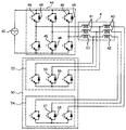
- FIG. 1 is a skeleton diagram showing a power transmission system of an electric vehicle equipped with a vehicle control device according to a first embodiment of the present invention. It is a figure which shows the electric circuit which connects the motor for driving
- a vehicle control apparatus according to a first embodiment of the present invention is mounted on an electric vehicle 1 including a power transmission system 2 shown in FIG.
- an electric vehicle 1 includes an electric motor 4 (hereinafter simply referred to as a motor 4) as a travel drive source, and an output shaft 6 of the motor 4 and an input shaft 10 of a speed reducer 8 are coaxial. Are connected to each other.
- the output shaft 14 of the speed reducer 8 is disposed in parallel to the input shaft 10, and has a drive gear 12 provided on the input shaft 10 and a diameter larger than that of the drive gear 12 and provided on the output shaft 14.
- the driven gear 16 is meshed. Thereby, the speed reducer 8 decelerates the rotation of the input shaft 10 and transmits it to the output shaft 14.
- an output gear 18 is provided on the output shaft 14 of the speed reducer 8, and the output gear 18 is meshed with an input gear 22 of a differential device 20 having a larger diameter than the output gear 18.
- the motor 4 is a three-phase motor driven by an alternating current, and has a first winding 61 and a second winding 62 connected in series with each other in each phase.
- the motor 4 (more specifically, the first winding 61 of each phase of the motor 4) is electrically connected to the battery 42 via the inverter 44.
- the inverter 44 includes, as semiconductor elements, a plurality of switching elements 46 made of, for example, IGBT and a plurality of rectifying elements 48 made of, for example, a diode.
- the inverter 44 converts power supplied from the battery 42 to the motor 4 from direct current to alternating current, and regenerative power from the motor 4 to the battery 42 is converted from alternating current to direct current. Control of the inverter 44 is executed by a control unit 40 described later.
- An energization mode switching unit 50 (energization mode switching means) is connected to the motor 4, and the energization mode of the motor 4 is energized to the first winding 61 and the second winding 62 by the energization mode switching unit 50.
- the low-speed mode is switched to the high-speed mode in which only the first winding 61 is energized.
- the energization mode switching operation by the energization mode switching unit 50 is controlled by the control unit 40 described later.
- the energization mode switching unit 50 includes a high-speed side energization unit 52 connected to each phase of the motor 4 in a portion between the first winding 61 and the second winding 62, and the first winding in the second winding 62.
- 61 has a low-speed energization section 54 connected to each phase of the motor 4 at the end opposite to 61.
- Each of these energization parts 52 and 54 has, as a semiconductor element, a plurality of switching elements 55 and 57 made of, for example, IGBT and a plurality of rectifying elements 56 and 58 made of, for example, a diode for each phase.
- the high speed side energization unit 52 is turned on and the low speed side energization unit 54 is turned off, so that only the high speed side energization unit 52 is energized in the energization mode switching unit 50. Only the wire 61 is energized.
- the low speed mode the high speed side energization unit 52 is turned off and the low speed side energization unit 54 is turned on, so that only the low speed side energization unit 54 is energized in the energization mode switching unit 50.
- the first winding 61 and the second winding 62 are energized.
- the number of turns of the entire energized portion in each phase of the motor 4 is reduced, and the induced voltage generated in the motor 4 is reduced.
- current easily flows from the battery 42 to the motor 4, and the motor 4 can be rotated at high speed.
- the low speed mode the number of turns of the entire energized portion in each phase of the motor 4 increases, and the induced voltage generated in the motor 4 increases, so that the current flow from the battery 42 to the motor 4 is suppressed, The motor 4 rotates at a relatively low speed.
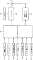
- the control unit 40 shown in FIG. 3 controls the inverter 44 and the energization mode switching unit 50. That is, the control unit 40 has both a function as inverter control means for controlling the inverter 44 and a function as switching control means for controlling the energization mode switching unit 50 (energization mode switching means).
- the control unit 40 includes a vehicle speed sensor 70 that detects the traveling speed of the electric vehicle 1, an accelerator amount sensor 72 that detects the amount of depression of the accelerator pedal, and a brake that detects the amount of depression of the brake pedal. Signals output from the sensor 74, a motor rotation speed sensor 76 (rotation speed detection means) that detects the rotation speed of the motor 4, and a range sensor 78 (range detection means) that detects the shift range selected by the driver. Is entered.
- a battery voltage sensor 80 for detecting the voltage of the battery 42 and a battery temperature for detecting the temperature of the battery 42 are used.
- the sensor 82 battery temperature detection means
- the sensor 82 is shown by a two-dot chain line, these sensors are used in other embodiments described later, and are not necessarily required in this embodiment.
- the control unit 40 performs arithmetic processing based on the signal sent from the sensor and outputs a control signal to the inverter 44 and the energization mode switching unit 50.
- the inverter 44 By controlling the inverter 44 by the control unit 40, the current flow between the battery 42 and the motor 4, that is, the supply power from the battery 42 to the motor 4 and the regenerative power from the motor 4 to the battery 42 are generated. It is controlled according to the driving state.
- the energization mode switching unit 50 is controlled by the control unit 40, whereby the energization mode of the motor 4 is switched between the low speed mode and the high speed mode. Specifically, the energization mode switching unit 50 is detected by the motor rotation speed sensor 76 so that the low-speed mode is set when the rotation speed detected by the motor rotation speed sensor 76 is less than a predetermined threshold value n. When the rotational speed is equal to or greater than the threshold value n, the high speed mode is controlled.
- the detection of the rotational speed of the motor 4 is not necessarily performed based on the output signal of the motor rotational speed sensor 76, and may be performed based on a control signal from the control unit 40 to the motor 4.
- the shift range selected by the driver includes a travel range such as a D range and a neutral range (N range).
- the control unit 40 controls the inverter 44 to supply the motor 4 with a current corresponding to the depression amount of the accelerator pedal. As a result, the motor 4 is driven and the driving force is transmitted to the drive wheels 36 and 38.
- the control unit 40 stops the control of the inverter 44. That is, the drive of the motor 4 is stopped by stopping the supply of current from the inverter 44 to the motor 4.
- the N range is not necessarily selected while the vehicle is stopped, but may be selected when the vehicle is decelerated.
- the power transmission system 2 of the electric vehicle 1 of this embodiment is not provided with a clutch, the connection between the motor 4 and the drive wheels 36 and 38 is always maintained even when the N range is selected. Therefore, even when the control of the inverter 44 is stopped at the time of deceleration in the N range, the motor 4 works to resist the rotation of the drive wheels 36 and 38, and a braking force called a regenerative brake is generated. 4 induces an induced voltage. Then, the driver feels uncomfortable that the regenerative brake is activated even though the N range is selected.
- the induced voltage generated in the motor 4 is higher than the voltage of the battery 42, a current that is not controlled by the inverter 44 flows from the motor 4 to the battery 42 via the rectifying element of the inverter 44. This is not preferable from the viewpoint of protecting the inverter 44, the battery 42, and peripheral components.
- the control unit 40 switches the energization mode of the motor 4 to the high speed mode as the regeneration suppression control for suppressing the deceleration regeneration.
- this regeneration suppression control is executed and the energization mode of the motor 4 is switched to the high speed mode, the motor 4 energizes only the first winding 61, and the number of turns of the entire energized portion in each phase of the motor 4 is increased.
- the induced voltage in the motor 4 and thus the current flow from the motor 4 to the battery 42 are reduced during deceleration because the current is reduced compared to the case where both the first winding 61 and the second winding 62 are energized. It is suppressed.
- the induced voltage of the motor 4 is a voltage proportional to the number of turns of the armature winding (the first winding 61 and the second winding 62) when the motor speed is the same. If the first winding 61 and the second winding 62 have the same number of turns, the magnitude of the induced voltage of the motor 4 can be reduced to half that in the low speed mode in the high speed mode, and the speed control range of the motor 4 can be expanded. Can do.
- the motor 4 is preferably configured such that the induced voltage generated in the motor 4 is always lower than the voltage of the battery 42 when the energization mode is the high-speed mode.
- the resistance of the motor 4 with respect to the rotation of the drive wheels 36 and 38 and the braking force due to the regenerative brake are suppressed during deceleration in the N range.
- the driver's discomfort with respect to operation can be reduced.
- the current flow from the motor 4 to the battery 42 is suppressed without being controlled by the inverter 44, so that the inverter 44, the battery 42, and peripheral components can be effectively protected.
- step S1 the output values of the motor rotation speed sensor 76 and the range sensor 78 are read based on the input signal to the control unit 40.
- step S2 it is determined whether or not the shift range is the N range based on the output value of the range sensor 78 read in step S1.
- step S3 it is determined whether or not the rotational speed of the motor 4 is greater than or equal to a threshold value n based on the output value of the motor rotational speed sensor 76 read in step S1.
- the energization mode switching unit 50 is controlled so that the energization mode of the motor 4 becomes the high speed mode (step S5). If the number is less than the threshold value n, the energization mode switching unit 50 is controlled so that the energization mode of the motor 4 becomes the low speed mode (step S4).
- step S2 determines whether the shift range is the N range. If the result of determination in step S2 is that the shift range is the N range, control of the inverter 44 is stopped (step S6) and energization is performed so that the energization mode of the motor 4 becomes the high-speed mode as regeneration suppression control.
- the mode switching unit 50 is controlled (step S5). That is, in this embodiment, as the regeneration suppression control, the energization mode is set not only in the high-speed rotation region where the rotation speed of the motor 4 is equal to or higher than the predetermined threshold value n but also in the low-speed rotation region where the rotation number is less than the threshold value n. Switch to high-speed mode. Thereby, when the shift range is the N range, the high speed mode is selected in the entire rotation range of the motor 4 (that is, regardless of the rotation speed of the motor 4).
- step S5 By executing such regeneration suppression control (step S5), when the vehicle 1 decelerates in a state where the N range is selected, the deceleration regeneration is suppressed, so the driver's response to the operation of the regenerative brake A sense of incongruity can be reduced, and current that is not controlled by the inverter 44 can be prevented from flowing from the motor 4 toward the battery 42, thereby effectively protecting the inverter 44, the battery 42, and peripheral components.
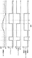
- FIG. 5 shows an example of the change over time of the energization mode of the motor 4 when the control operation shown in FIG. 4 is performed.
- the automobile 1 In the initial state shown in FIG. 5, the automobile 1 is traveling at a low speed with the D range selected, the energization mode of the motor 4 is the low speed mode, and the control of the inverter 44 is being executed.
- Step S6 in FIG. 4 the control of the inverter 44 is stopped (step S6 in FIG. 4), and the regeneration suppression control for switching the energization mode of the motor 4 to the high speed mode is executed. (Step S5 in FIG. 4).
- this regeneration suppression control the flow of current from the motor 4 to the battery 42 is suppressed while the braking force by the regenerative brake is suppressed.
- step S6 the control of the inverter 44 is stopped (step S6 in FIG. 4), and the energization mode of the motor 4 is maintained in the high speed mode by the regeneration suppression control (FIG. 4 step S5).
- the rotational speed of the motor 4 gradually decreases and falls below the threshold value n at time t5.
- the shift range remains at the N range, the energization mode of the motor 4 is maintained in the high speed mode without being switched to the low speed mode by continuing the regeneration suppression control (step S5 in FIG. 4). Thereby, the electric power regeneration from the motor 4 to the battery 42 and the braking force by the regenerative brake can be continuously suppressed.
- the electric vehicle 1 of the second embodiment is provided with a battery voltage sensor 80 (FIG. 3) that detects the voltage of the battery 42.
- a battery voltage sensor 80 FIG. 3
- Other points are basically the same as those of the first embodiment described above.
- FIG. 6 is a flowchart showing the contents of energization mode switching control executed while the electric vehicle 1 is traveling in the second embodiment.
- step S11 the output values of the motor rotation speed sensor 76, the range sensor 78, and the battery voltage sensor 80 are read based on the input signal to the control unit 40.
- step S12 it is determined whether or not the shift range is the N range based on the output value of the range sensor 78 read in step S11.
- step S12 If the result of determination in step S12 is that the shift range is not the N range, that is, if the travel range is the D range or the like, normal switching control according to the rotational speed of the motor 4 is executed in steps S13 to S16. .
- a first threshold value n1 is set as a threshold value n that serves as a reference when the energization mode of the motor 4 is switched.
- the first threshold n1 may be a fixed value determined in advance, or may be a value that is changed according to the driving state or the like.
- step S14 it is determined whether or not the rotational speed of the motor 4 is equal to or greater than the first threshold value n1 based on the output value of the motor rotational speed sensor 76 read in step S11. If the result of determination in step S14 is that the rotation speed of the motor 4 is equal to or greater than the first threshold value n1, the energization mode switching unit 50 is controlled so that the energization mode of the motor 4 becomes the high speed mode (step S15). If the rotational speed of 4 is less than the first threshold value n1, the energization mode switching unit 50 is controlled so that the energization mode of the motor 4 becomes the low speed mode (step S16).
- step S12 determines whether the shift range is the N range. If the result of determination in step S12 is that the shift range is the N range, control of the inverter 44 is stopped (step S17). And regeneration suppression control is performed only when the further conditions are satisfied.
- the control unit 40 sets the second threshold value n2 as a reference for executing the regeneration suppression control separately from the first threshold value n1 (see step S13).
- the regeneration suppression control is executed only when the second threshold value n2 is less than the first threshold value n1 (step S18 to step S20). That is, if the second threshold value n2 is less than the first threshold value n1, not only the high-speed rotation region where the rotation speed of the motor 4 is equal to or higher than the first threshold value n1 but also the low-speed rotation region. Even in a part (the rotation range between the second threshold value n2 and the first threshold value n1), the energization mode is switched to the high speed mode, which leads to suppression of deceleration regeneration.
- the energization mode is not switched to the high speed mode unless the motor rotation speed is equal to or greater than the second threshold value n2.
- the rotational speed of the motor 4 is less than the second threshold value n2, that is, when the induced voltage generated in the motor 4 is sufficiently lower than the voltage of the battery 42 even when the energization mode of the motor 4 is kept at the low speed mode.
- the energization mode remains in the low speed mode. Thereby, unnecessary switching to the high-speed mode is avoided, so that the switching frequency of the energization mode can be reduced.
- the second threshold value n2 is calculated based on the voltage of the battery 42.
- the second threshold value n2 is calculated so as to decrease as the voltage detected by the battery voltage sensor 80 decreases.
- the lower the voltage of the battery 42 and the easier the current flows from the motor 4 to the battery 42 the smaller the second threshold value n2 is calculated, and the regeneration suppression control becomes easier to execute.
- the second threshold value n2 is variably setting according to the voltage of the battery 42, it is possible to achieve a balance between suppression of the switching frequency of the energization mode of the motor 4 and suppression of deceleration regeneration.
- step S19 whether or not the second threshold value n2 calculated in step S18 is lower than the first threshold value n1, that is, whether or not the second threshold value n2 is an appropriate value as a regeneration suppression threshold value. Is determined.
- step S19 when the second threshold value n2 is equal to or greater than the first threshold value n1, the second threshold value n2 is inappropriate as a regeneration suppression threshold value. Therefore, as the threshold value n serving as a reference when switching the energization mode, the first threshold value n1 is adopted instead of the second threshold value n2 (step S13), and the energization mode is determined with the first threshold value n1 as a boundary. It is switched (steps S14 to S16). Such control does not correspond to the normal switching control that is executed when the shift range is other than the N range (traveling range such as the D range), and therefore does not correspond to the regeneration suppression control that suppresses deceleration regeneration.
- the second threshold value n2 is an appropriate value as a regeneration suppression threshold value, and therefore the threshold value n for switching the energization mode As the second threshold value n2, the second threshold value n2 is employed (step S20). Then, after determining whether or not the rotational speed of the motor 4 is equal to or higher than the second threshold value n2 (step S14), only when the rotational speed of the motor 4 is equal to or higher than the second threshold value n2 based on the determination result. The energization mode of the motor 4 is set to the high speed mode (step S15).
- the second threshold value n2 lower than the first threshold value n1 that is a threshold value at the normal time (when the shift range is the traveling range) is set, and the energization mode is set to a high speed when the threshold value is equal to or higher than the second threshold value n2.
- Switching to the mode leads to increasing the frequency of the high-speed mode by expanding the rotation range where the energization mode is set to the high-speed mode. Therefore, the control here (control to switch to the high speed mode in step S15) corresponds to regeneration suppression control that suppresses deceleration regeneration.
- unnecessary regeneration suppression control can be omitted according to the voltage of the battery 42 to suppress the switching frequency of the energization mode of the motor 4, while regeneration suppression control is performed when necessary.
- the power regeneration from the motor 4 to the battery 42 and the braking force due to the regenerative brake can be suppressed.
- FIG. 7 shows an example of the change over time of the energization mode of the motor 4 when the control operation shown in FIG. 6 is performed.
- the automobile 1 In the initial state shown in FIG. 7, the automobile 1 is traveling at a low speed with the D range selected, and the threshold value n for switching the energization mode is set to the first threshold value n1.
- the energization mode of the motor 4 is the low speed mode, and the control of the inverter 44 is executed.
- the control of the inverter 44 is stopped (step S17 in FIG. 6), and the threshold value n for switching the energization mode is changed from the first threshold value n1 to the second threshold value.
- the threshold value n2 ( ⁇ n1) (step S20 in FIG. 6).
- the energization mode of the motor 4 is maintained in the low speed mode. Thereby, the switching frequency of the energization mode is reduced.
- the shift range is returned to the D range, and accordingly, the control of the inverter 44 is resumed, and the threshold value for switching the energization mode is returned to the first threshold value n1 (step S13 in FIG. 6). .
- the rotational speed of the motor 4 increases and exceeds the second threshold value n2, but does not reach the first threshold value n1, so that the energization mode of the motor 4 is maintained in the low speed mode.
- the shift range is again switched to the N range, and accordingly, the control of the inverter 44 is stopped again (step S17 in FIG. 6), and the threshold value n for switching the energization mode is again set to the second threshold value.
- n2 is changed (step S20 in FIG. 6).
- the energization mode of the motor 4 is switched to the high speed mode (step S15 in FIG. 6).
- the second threshold value n2 lower than the first threshold value n1 set at the normal time is set, and the energization mode is switched to the high-speed mode in the rotation region that is equal to or higher than the second threshold value n2.
- regeneration suppression control is executed, and power regeneration from the motor 4 to the battery 42 and braking force by regenerative braking are suppressed.
- the control of the inverter 44 is resumed, and the threshold value n for switching the energization mode is again returned to the first threshold value n1.
- the energization mode is not switched.
- the energization mode when the shift range is the N range, as the regeneration suppression control, the energization mode is switched to the high speed mode regardless of the number of rotations of the motor 4 (in all rotation regions), while the second
- the energization mode when the shift range is the N range, as the regeneration suppression control, the energization mode is switched to the high speed mode only in the rotation region where the rotation speed of the motor 4 is equal to or higher than the second threshold value n2.
- the regeneration suppression when the condition that the shift range is the N range and the condition that the voltage of the battery 42 detected by the battery voltage sensor 80 is less than a predetermined voltage are both established, the regeneration suppression is performed.
- Control (control for switching the energization mode to the high speed mode in the entire rotation range of the motor or the rotation range equal to or higher than the second threshold value n2) may be executed.
- the regeneration suppression control since the voltage of the battery 42 is less than the predetermined voltage, the regeneration suppression control is executed only when the current is likely to flow from the motor 4 to the battery 42, so that switching to an unnecessary high-speed mode is suppressed. Become. Thus, unnecessary power regeneration and regenerative braking can be suppressed by switching to the high speed mode only when necessary according to the voltage of the battery 42.
- both the condition that the shift range is the N range and the condition that the temperature of the battery 42 detected by the battery temperature sensor 82 (FIG. 3) is equal to or higher than a predetermined temperature are both present.
- regeneration suppression control may be executed.
- the regenerative suppression control suppresses charging of the regenerative power to the battery 42.
- the temperature rise of 42 can be suppressed.
- the present invention is not limited to an electric vehicle, but can be applied to a hybrid vehicle.
- the vehicle control device includes a battery (42), at least a first winding (61) and a second winding (62) connected in series with each other, and is connected to the wheels (36, 38).
- a vehicle driving motor (4) provided to be always maintained, and an inverter (44) provided between the battery (42) and the motor (4) to electrically connect both; Applies to vehicles with The control device energizes at least the first winding (61) and the second winding (62) in an energization mode of the inverter control means (40) for controlling the inverter (44) and the motor (4).
- the energization mode switching means (50) is controlled so that the energization mode becomes a low speed mode, while the rotational speed detection means (76)
- the inverter control means (40) stops the control of the inverter (44) when a neutral range is detected by the range detection means (78), and the switching control means (40) When the neutral range is detected by the detection means (78), not only the high-speed rotation range where the rotation speed of the motor (4) is equal to or greater than the predetermined threshold (n), but also the rotation range on the low-speed side. Regeneration suppression control for switching the energization mode to the high speed mode is executed even at least in part.
- the energization mode of the vehicle drive motor is set to the high-speed mode in a wider rotation range, and the first winding and the second winding connected in series in the motor. Since only the first winding is energized, the number of turns of the entire energized portion of the motor is relatively small. Therefore, when decelerating, the induced voltage in the motor, and thus the current flow from the motor to the battery, is reduced. It is suppressed.
- the switching control means (40) sets the energization mode as the regeneration suppression control regardless of the rotation speed of the motor (4). Switch to high-speed mode.
- the energization mode is switched to the high speed mode regardless of the rotation speed of the motor (in the entire rotation range of the motor), the regenerative power charged from the motor to the battery during deceleration in the N range. And the braking force generated by the regenerative braking can be more reliably suppressed.
- the switching control means (40) is configured such that when the shift from the travel range to the neutral range is detected by the range detection means (78) in a state where the energization mode is the high speed mode, Even if the rotational speed detected by the rotational speed detection means (76) falls below the threshold value (n), the energization mode is maintained in the high speed mode.
- the energization mode is not changed even if the motor rotation speed decreases below the threshold after the switching. Since the high-speed mode is maintained, it is possible to prevent an induced voltage generated in the motor from increasing, and it is possible to continuously suppress power regeneration from the motor to the battery and braking force by the regenerative brake.
- the control device when the shift from the travel range to the neutral range is detected by the range detection means (78), a regeneration suppression threshold value (n2) that serves as a reference when performing the regeneration suppression control Threshold setting means (40) is further provided.
- the switching control means (40) detects the neutral range by the range detection means (78), and the regeneration suppression threshold (n2) set by the threshold setting means (40) is the predetermined threshold ( When it is less than n1), as the regeneration suppression control, the energization mode is switched to the high speed mode in a rotation range where the rotation speed of the motor (4) is equal to or greater than the regeneration suppression threshold (n2).
- the regeneration suppression threshold is set separately from the energization mode switching threshold (predetermined threshold).
- predetermined threshold the energization mode switching threshold
- the regeneration suppression threshold is less than the predetermined threshold and the rotation speed of the motor is less than the regeneration suppression threshold
- the induced voltage generated in the motor is higher than the battery voltage even when the energization mode is kept at the low speed mode.
- Expected to be lower by leaving the energization mode at the low speed mode, unnecessary switching to the high speed mode can be avoided and the frequency of switching the energization mode can be reduced.
- the energization mode is set to the high speed mode, so that power regeneration from the motor to the battery and regenerative braking Power can be suppressed.
- the control device includes battery voltage detection means (80) for detecting the voltage of the battery (42), and the threshold setting means (40) is the battery voltage detection means (80).
- the regeneration suppression threshold value (n2) is set to be smaller as the voltage detected by (1) is lower.
- control device includes battery voltage detection means (80) for detecting the voltage of the battery (42).
- the switching control means (40) is configured to suppress the regeneration when a neutral range is detected by the range detection means (78) and the voltage detected by the battery voltage detection means (80) is less than a predetermined voltage. Execute control.
- the regeneration suppression control is executed only when the current from the motor tends to flow from the motor to the battery because the battery voltage is less than the predetermined voltage. While switching to the mode is suppressed, switching to the high speed mode is executed when necessary according to the voltage of the battery, so that unnecessary power regeneration and regenerative braking can be suppressed.
- control device includes battery temperature detection means (82) for detecting the temperature of the battery.
- the switching control means (40) is configured to suppress the regeneration when a neutral range is detected by the range detection means (78) and the temperature detected by the battery temperature detection means (82) is equal to or higher than a predetermined temperature. Execute control.
Landscapes
- Engineering & Computer Science (AREA)
- Power Engineering (AREA)
- Transportation (AREA)
- Mechanical Engineering (AREA)
- Life Sciences & Earth Sciences (AREA)
- Sustainable Development (AREA)
- Sustainable Energy (AREA)
- Electric Propulsion And Braking For Vehicles (AREA)
- Control Of Ac Motors In General (AREA)
Abstract
Description
本発明の第1の実施形態に係る車両の制御装置は、図1に示す動力伝達系2を備えた電気自動車1に搭載される。
次に、本発明の第2の実施形態について説明する。この第2の実施形態の電気自動車1には、バッテリ42の電圧を検出するバッテリ電圧センサ80(図3)が設けられている。なお、これ以外の点については、上述した第1の実施形態と基本的に同じ構造である。
Claims (8)
- バッテリと、
相互に直列接続された少なくとも第1巻線と第2巻線とを有し、且つ車輪との連結が常に維持されるように設けられた車両駆動用のモータと、
前記バッテリと前記モータとの間に設けられて両者を電気的に接続するインバータと、を備えた車両を制御する装置であって、
前記インバータを制御するインバータ制御手段と、
前記モータの通電モードを、少なくとも第1巻線および第2巻線に通電する低速モードと、第1巻線にのみ通電する高速モードとの間で切り換える通電モード切換手段と、
前記モータの回転数を検出する回転数検出手段と、
運転者により選択されたシフトレンジを検出するレンジ検出手段と、
前記レンジ検出手段により検出されたシフトレンジが走行レンジである場合において、前記回転数検出手段により検出された回転数が所定の閾値未満であるときは、前記通電モードが低速モードとなるように前記通電モード切換手段を制御する一方、前記回転数検出手段により検出された回転数が前記所定の閾値以上であるときは、前記通電モードが高速モードとなるように前記通電モード切換手段を制御する切換制御手段と、を備え、
前記インバータ制御手段は、前記レンジ検出手段により中立レンジが検出されたときは前記インバータの制御を停止するものであり、
前記切換制御手段は、前記レンジ検出手段により中立レンジが検出されたとき、前記モータの回転数が前記所定の閾値以上となる高速側の回転域だけでなく、それよりも低速側の回転域の少なくとも一部でも前記通電モードを前記高速モードに切り換える回生抑制制御を実行することを特徴とする車両の制御装置。 - 前記切換制御手段は、前記レンジ検出手段により中立レンジが検出されたとき、前記回生抑制制御として、前記モータの回転数にかかわらず前記通電モードを前記高速モードに切り換えることを特徴とする請求項1記載の車両の制御装置。
- 前記切換制御手段は、前記通電モードが高速モードである状態において前記レンジ検出手段により走行レンジから中立レンジへのシフトが検出されたとき、前記回転数検出手段により検出される回転数が前記閾値未満に低下しても、前記通電モードを高速モードに維持することを特徴とする請求項2に記載の車両の制御装置。
- 前記レンジ検出手段により走行レンジから中立レンジへのシフトが検出されたときに、前記回生抑制制御を実行する際の基準となる回生抑制用閾値を設定する閾値設定手段を更に備え、
前記切換制御手段は、前記レンジ検出手段により中立レンジが検出され、且つ、前記閾値設定手段により設定された前記回生抑制用閾値が前記所定の閾値未満であったときに、前記回生抑制制御として、前記モータの回転数が前記回生抑制用閾値以上となる回転域で前記通電モードを前記高速モードに切り換えることを特徴とする請求項1に記載の車両の制御装置。 - 前記バッテリの電圧を検出するバッテリ電圧検出手段を備え、
前記閾値設定手段は、前記バッテリ電圧検出手段により検出された電圧が低いほど前記回生抑制用閾値を小さく設定することを特徴とする請求項4に記載の車両の制御装置。 - 前記バッテリの電圧を検出するバッテリ電圧検出手段を備え、
前記切換制御手段は、前記レンジ検出手段により中立レンジが検出され、且つ、前記バッテリ電圧検出手段により検出された電圧が所定電圧未満であるときに、前記回生抑制制御を実行することを特徴とする請求項1に記載の車両の制御装置。 - 前記バッテリの温度を検出するバッテリ温度検出手段を備え、
前記切換制御手段は、前記レンジ検出手段により中立レンジが検出され、且つ、前記バッテリ温度検出手段により検出された温度が所定温度以上であるときに、前記回生抑制制御を実行することを特徴とする請求項1に記載の車両の制御装置。 - バッテリと、
相互に直列接続された少なくとも第1巻線と第2巻線とを有し、且つ車輪との連結が常に維持されるように設けられた車両駆動用のモータと、
前記バッテリと前記モータとの間に設けられて両者を電気的に接続するインバータと、を備えた車両を制御する方法であって、
前記モータの回転数を検出する第1のステップと、
運転者により選択されたシフトレンジを検出する第2のステップと、
前記第2のステップで検出されたシフトレンジが走行レンジである場合において、前記第1のステップで検出された前記モータの回転数が所定の閾値未満であるときは、前記モータの通電モードを、少なくとも前記第1巻線および第2巻線に通電する低速モードとする一方、前記検出された前記モータの回転数が前記所定の閾値以上であるときは、前記モータの通電モードを、前記第1巻線にのみ通電する高速モードに切り換える第3のステップと、
前記第2のステップで検出されたシフトレンジが中立レンジである場合に、前記インバータの制御を停止するとともに、回生抑制制御として、前記モータの回転数が前記所定の閾値以上となる高速側の回転域だけでなく、それよりも低速側の回転域の少なくとも一部でも前記通電モードを前記高速モードに切り換える第4のステップと、を含むことを特徴とする車両の制御方法。
Priority Applications (3)
| Application Number | Priority Date | Filing Date | Title |
|---|---|---|---|
| DE112012001520T DE112012001520T5 (de) | 2011-03-31 | 2012-02-03 | Fahrzeugsteuervorrichtung und -steuerverfahren |
| US14/004,650 US9236825B2 (en) | 2011-03-31 | 2012-02-03 | Vehicle control device and control method |
| CN201280010825.0A CN103442932B (zh) | 2011-03-31 | 2012-02-03 | 车辆的控制装置及控制方法 |
Applications Claiming Priority (2)
| Application Number | Priority Date | Filing Date | Title |
|---|---|---|---|
| JP2011078709A JP5722683B2 (ja) | 2011-03-31 | 2011-03-31 | 車両の制御装置 |
| JP2011-078709 | 2011-03-31 |
Publications (1)
| Publication Number | Publication Date |
|---|---|
| WO2012132188A1 true WO2012132188A1 (ja) | 2012-10-04 |
Family
ID=46929985
Family Applications (1)
| Application Number | Title | Priority Date | Filing Date |
|---|---|---|---|
| PCT/JP2012/000742 Ceased WO2012132188A1 (ja) | 2011-03-31 | 2012-02-03 | 車両の制御装置及び制御方法 |
Country Status (5)
| Country | Link |
|---|---|
| US (1) | US9236825B2 (ja) |
| JP (1) | JP5722683B2 (ja) |
| CN (1) | CN103442932B (ja) |
| DE (1) | DE112012001520T5 (ja) |
| WO (1) | WO2012132188A1 (ja) |
Families Citing this family (15)
| Publication number | Priority date | Publication date | Assignee | Title |
|---|---|---|---|---|
| JP5969240B2 (ja) * | 2012-03-28 | 2016-08-17 | アスモ株式会社 | 3相交流電動機に備えた巻線切換装置、3相交流電動機に備えた巻線切換装置の切換スイッチング素子のショート故障検出方法及び3相交流電動機に備えた巻線切換装置の切換スイッチング素子のオープン故障検出方法 |
| CN103281034B (zh) * | 2013-05-03 | 2015-05-13 | 哈尔滨工业大学 | 多相电机绕组切换电路 |
| JP6257290B2 (ja) * | 2013-12-04 | 2018-01-10 | 日立ジョンソンコントロールズ空調株式会社 | 密閉型電動圧縮機 |
| KR101628545B1 (ko) * | 2014-11-27 | 2016-06-08 | 현대자동차주식회사 | 하이브리드 차량의 회생제동 제어방법 |
| JP6107865B2 (ja) * | 2015-03-27 | 2017-04-05 | マツダ株式会社 | 電動車両用駆動装置 |
| JP6264333B2 (ja) * | 2015-07-03 | 2018-01-24 | 株式会社豊田自動織機 | モータ駆動装置 |
| KR102490606B1 (ko) * | 2015-11-26 | 2023-01-19 | 현대모비스 주식회사 | 차량용 모터 제어 시스템 및 동작 방법 |
| JP2017169363A (ja) * | 2016-03-16 | 2017-09-21 | 三菱自動車工業株式会社 | 車両の制御装置 |
| US10658966B2 (en) * | 2016-08-02 | 2020-05-19 | Mitsubishi Electric Corporation | Motor driving apparatus, refrigerator, and air conditioner |
| AU2017424860B2 (en) * | 2017-07-25 | 2020-10-22 | Mitsubishi Electric Corporation | Driving device, compressor, air conditioner, and driving method |
| US11398790B2 (en) * | 2017-07-28 | 2022-07-26 | Mitsubishi Electric Corporation | Air conditioner |
| DE102017220136A1 (de) * | 2017-11-13 | 2019-05-16 | Knorr-Bremse Systeme für Nutzfahrzeuge GmbH | Elektronik mit einer oder mehreren Endstufeneinheiten für den Betrieb von zwei oder mehreren Motoreinheiten |
| CN108715140B (zh) * | 2018-06-08 | 2023-05-23 | 华南理工大学 | 一种采用可变绕组永磁同步电机的电子式换挡系统 |
| CN110149077A (zh) * | 2019-04-04 | 2019-08-20 | 东风电驱动系统有限公司 | 一种绕组可切换电机及其绕组切换方法、电动机、发电机 |
| JP7547301B2 (ja) | 2021-09-21 | 2024-09-09 | 本田技研工業株式会社 | 電力供給回路及び回転電機システム |
Citations (3)
| Publication number | Priority date | Publication date | Assignee | Title |
|---|---|---|---|---|
| JPH06217596A (ja) * | 1993-01-19 | 1994-08-05 | Toyota Motor Corp | 巻線切替式永久磁石モータの制御装置 |
| JPH06276607A (ja) * | 1993-03-18 | 1994-09-30 | Toyota Motor Corp | 電気自動車の駆動力制御装置 |
| JP2010088222A (ja) * | 2008-09-30 | 2010-04-15 | Mazda Motor Corp | 電動車両のモータ制御方法および電動車両用駆動装置 |
Family Cites Families (10)
| Publication number | Priority date | Publication date | Assignee | Title |
|---|---|---|---|---|
| JP3200901B2 (ja) | 1991-12-20 | 2001-08-20 | 株式会社日立製作所 | 電気自動車の駆動装置 |
| JPH06225588A (ja) | 1993-01-21 | 1994-08-12 | Toyota Motor Corp | 巻線切替式永久磁石モータの制御装置 |
| JP3248997B2 (ja) | 1993-09-29 | 2002-01-21 | 株式会社日立製作所 | インバータ制御装置 |
| JP3400042B2 (ja) | 1993-10-08 | 2003-04-28 | 株式会社日本自動車部品総合研究所 | 電気自動車の制動力制御装置 |
| JPH08331895A (ja) * | 1995-05-31 | 1996-12-13 | Kyocera Corp | モーター及びその制御方法 |
| US5720690A (en) * | 1995-06-16 | 1998-02-24 | Aisin Aw Co., Ltd. | Shift control system for controlling a transmission of a vehicle having an engine and a motor generator drive source |
| JP3879736B2 (ja) * | 2003-12-19 | 2007-02-14 | 日産自動車株式会社 | 4輪駆動車両の駆動制御装置 |
| JP4424418B2 (ja) * | 2007-12-26 | 2010-03-03 | トヨタ自動車株式会社 | 燃料電池システム及び燃料電池車両 |
| JP5558697B2 (ja) * | 2008-11-27 | 2014-07-23 | マツダ株式会社 | ハイブリッド車両のモータ制御装置 |
| WO2012117623A1 (ja) * | 2011-02-28 | 2012-09-07 | アイシン・エィ・ダブリュ株式会社 | 電動車両用駆動装置 |
-
2011
- 2011-03-31 JP JP2011078709A patent/JP5722683B2/ja not_active Expired - Fee Related
-
2012
- 2012-02-03 DE DE112012001520T patent/DE112012001520T5/de not_active Withdrawn
- 2012-02-03 US US14/004,650 patent/US9236825B2/en not_active Expired - Fee Related
- 2012-02-03 CN CN201280010825.0A patent/CN103442932B/zh not_active Expired - Fee Related
- 2012-02-03 WO PCT/JP2012/000742 patent/WO2012132188A1/ja not_active Ceased
Patent Citations (3)
| Publication number | Priority date | Publication date | Assignee | Title |
|---|---|---|---|---|
| JPH06217596A (ja) * | 1993-01-19 | 1994-08-05 | Toyota Motor Corp | 巻線切替式永久磁石モータの制御装置 |
| JPH06276607A (ja) * | 1993-03-18 | 1994-09-30 | Toyota Motor Corp | 電気自動車の駆動力制御装置 |
| JP2010088222A (ja) * | 2008-09-30 | 2010-04-15 | Mazda Motor Corp | 電動車両のモータ制御方法および電動車両用駆動装置 |
Also Published As
| Publication number | Publication date |
|---|---|
| US9236825B2 (en) | 2016-01-12 |
| JP5722683B2 (ja) | 2015-05-27 |
| US20140009097A1 (en) | 2014-01-09 |
| CN103442932B (zh) | 2015-12-02 |
| CN103442932A (zh) | 2013-12-11 |
| JP2012213306A (ja) | 2012-11-01 |
| DE112012001520T5 (de) | 2013-12-24 |
Similar Documents
| Publication | Publication Date | Title |
|---|---|---|
| JP5722683B2 (ja) | 車両の制御装置 | |
| JP6690712B2 (ja) | トルク制御方法及びトルク制御装置 | |
| JP6396180B2 (ja) | 車輪独立駆動式車両の駆動制御装置 | |
| JP6534509B2 (ja) | 車輪独立駆動式車両の駆動制御装置 | |
| JP6517089B2 (ja) | 車輪独立駆動式車両の駆動制御装置 | |
| WO2013069718A1 (ja) | 電気自動車 | |
| JP2013150477A (ja) | 車両の駆動装置 | |
| WO2014148427A1 (ja) | モータ駆動装置 | |
| JP2013215063A (ja) | 電気自動車のクリープ制御装置 | |
| JP2013146116A (ja) | 電気自動車のコンデンサ電荷放電装置 | |
| JP2011172324A (ja) | インバータ制御装置 | |
| JP2016063597A (ja) | 駆動制御装置 | |
| JP2015171205A (ja) | 車両の制御装置 | |
| JP2005045864A (ja) | 電気自動車およびその制御方法 | |
| JP2013251988A (ja) | モータジェネレータ制御装置 | |
| JP5598103B2 (ja) | 電動車両のモータロック対策制御装置 | |
| JP2017099139A (ja) | モータ制御システム | |
| JP2017143654A (ja) | 電気自動車 | |
| JP5240004B2 (ja) | 車両制御装置 | |
| JP5496294B2 (ja) | 車両共振抑制制御装置 | |
| JP2014121226A (ja) | モータ駆動装置 | |
| JP6137045B2 (ja) | 車両の駆動電動機制御装置 | |
| JP2013244875A (ja) | 車両 | |
| JP2012170282A (ja) | 車両用駆動制御装置 | |
| JP4752282B2 (ja) | 電動モータ式4輪駆動車両のモータ駆動制御装置 |
Legal Events
| Date | Code | Title | Description |
|---|---|---|---|
| 121 | Ep: the epo has been informed by wipo that ep was designated in this application |
Ref document number: 12765714 Country of ref document: EP Kind code of ref document: A1 |
|
| WWE | Wipo information: entry into national phase |
Ref document number: 14004650 Country of ref document: US |
|
| WWE | Wipo information: entry into national phase |
Ref document number: 112012001520 Country of ref document: DE Ref document number: 1120120015207 Country of ref document: DE |
|
| 122 | Ep: pct application non-entry in european phase |
Ref document number: 12765714 Country of ref document: EP Kind code of ref document: A1 |