WO2012128187A1 - グラファイトフィルムの製造方法および炭化フィルムの製造方法 - Google Patents
グラファイトフィルムの製造方法および炭化フィルムの製造方法 Download PDFInfo
- Publication number
- WO2012128187A1 WO2012128187A1 PCT/JP2012/056778 JP2012056778W WO2012128187A1 WO 2012128187 A1 WO2012128187 A1 WO 2012128187A1 JP 2012056778 W JP2012056778 W JP 2012056778W WO 2012128187 A1 WO2012128187 A1 WO 2012128187A1
- Authority
- WO
- WIPO (PCT)
- Prior art keywords
- film
- temperature
- producing
- heating space
- polymer film
- Prior art date
- Legal status (The legal status is an assumption and is not a legal conclusion. Google has not performed a legal analysis and makes no representation as to the accuracy of the status listed.)
- Ceased
Links
Images




Classifications
-
- C—CHEMISTRY; METALLURGY
- C01—INORGANIC CHEMISTRY
- C01B—NON-METALLIC ELEMENTS; COMPOUNDS THEREOF; METALLOIDS OR COMPOUNDS THEREOF NOT COVERED BY SUBCLASS C01C
- C01B32/00—Carbon; Compounds thereof
- C01B32/20—Graphite
- C01B32/205—Preparation
-
- C—CHEMISTRY; METALLURGY
- C04—CEMENTS; CONCRETE; ARTIFICIAL STONE; CERAMICS; REFRACTORIES
- C04B—LIME, MAGNESIA; SLAG; CEMENTS; COMPOSITIONS THEREOF, e.g. MORTARS, CONCRETE OR LIKE BUILDING MATERIALS; ARTIFICIAL STONE; CERAMICS; REFRACTORIES; TREATMENT OF NATURAL STONE
- C04B35/00—Shaped ceramic products characterised by their composition; Ceramics compositions; Processing powders of inorganic compounds preparatory to the manufacturing of ceramic products
- C04B35/515—Shaped ceramic products characterised by their composition; Ceramics compositions; Processing powders of inorganic compounds preparatory to the manufacturing of ceramic products based on non-oxide ceramics
- C04B35/52—Shaped ceramic products characterised by their composition; Ceramics compositions; Processing powders of inorganic compounds preparatory to the manufacturing of ceramic products based on non-oxide ceramics based on carbon, e.g. graphite
- C04B35/522—Graphite
-
- C—CHEMISTRY; METALLURGY
- C01—INORGANIC CHEMISTRY
- C01B—NON-METALLIC ELEMENTS; COMPOUNDS THEREOF; METALLOIDS OR COMPOUNDS THEREOF NOT COVERED BY SUBCLASS C01C
- C01B32/00—Carbon; Compounds thereof
- C01B32/05—Preparation or purification of carbon not covered by groups C01B32/15, C01B32/20, C01B32/25, C01B32/30
-
- C—CHEMISTRY; METALLURGY
- C04—CEMENTS; CONCRETE; ARTIFICIAL STONE; CERAMICS; REFRACTORIES
- C04B—LIME, MAGNESIA; SLAG; CEMENTS; COMPOSITIONS THEREOF, e.g. MORTARS, CONCRETE OR LIKE BUILDING MATERIALS; ARTIFICIAL STONE; CERAMICS; REFRACTORIES; TREATMENT OF NATURAL STONE
- C04B35/00—Shaped ceramic products characterised by their composition; Ceramics compositions; Processing powders of inorganic compounds preparatory to the manufacturing of ceramic products
- C04B35/515—Shaped ceramic products characterised by their composition; Ceramics compositions; Processing powders of inorganic compounds preparatory to the manufacturing of ceramic products based on non-oxide ceramics
- C04B35/52—Shaped ceramic products characterised by their composition; Ceramics compositions; Processing powders of inorganic compounds preparatory to the manufacturing of ceramic products based on non-oxide ceramics based on carbon, e.g. graphite
- C04B35/524—Shaped ceramic products characterised by their composition; Ceramics compositions; Processing powders of inorganic compounds preparatory to the manufacturing of ceramic products based on non-oxide ceramics based on carbon, e.g. graphite obtained from polymer precursors, e.g. glass-like carbon material
-
- C—CHEMISTRY; METALLURGY
- C04—CEMENTS; CONCRETE; ARTIFICIAL STONE; CERAMICS; REFRACTORIES
- C04B—LIME, MAGNESIA; SLAG; CEMENTS; COMPOSITIONS THEREOF, e.g. MORTARS, CONCRETE OR LIKE BUILDING MATERIALS; ARTIFICIAL STONE; CERAMICS; REFRACTORIES; TREATMENT OF NATURAL STONE
- C04B35/00—Shaped ceramic products characterised by their composition; Ceramics compositions; Processing powders of inorganic compounds preparatory to the manufacturing of ceramic products
- C04B35/622—Forming processes; Processing powders of inorganic compounds preparatory to the manufacturing of ceramic products
- C04B35/62218—Forming processes; Processing powders of inorganic compounds preparatory to the manufacturing of ceramic products obtaining ceramic films, e.g. by using temporary supports
-
- H—ELECTRICITY
- H10—SEMICONDUCTOR DEVICES; ELECTRIC SOLID-STATE DEVICES NOT OTHERWISE PROVIDED FOR
- H10W—GENERIC PACKAGES, INTERCONNECTIONS, CONNECTORS OR OTHER CONSTRUCTIONAL DETAILS OF DEVICES COVERED BY CLASS H10
- H10W40/00—Arrangements for thermal protection or thermal control
- H10W40/20—Arrangements for cooling
- H10W40/25—Arrangements for cooling characterised by their materials
Definitions
- the present invention relates to a method for producing a graphite film and a method for producing a carbonized film including a continuous carbonization step of continuously firing a polymer film continuous in the longitudinal direction.
- Polymer fired type graphite film has excellent heat dissipation characteristics, so it is used as a heat dissipation component for semiconductor elements and other heat generating components mounted on various electronic or electric devices such as computers.
- a sheet-like polymer film is heat-treated in a batch system.
- a method of continuously firing a polymer film continuous in the longitudinal direction has been developed.
- Patent Document 1 discloses a method of continuous baking while applying tension to a long polymer film
- Patent Document 2 discloses a method of continuous processing without applying tension as much as possible.
- Japanese Patent Publication Japanese Patent Laid-Open No. 4-149013 (published on May 22, 1992) Japanese Patent Publication “Japanese Patent Laid-Open No. 2004-299937 (published Oct. 28, 2004)”
- An object of the present invention is to provide a method for producing a graphite film and a method for producing a carbonized film in which wrinkles during continuous firing of a polymer film are suppressed.
- this invention relates to the manufacturing method of a graphite film including the continuous carbonization process containing the heating space of 2 steps
- the present invention relates to a method for producing a graphite film including a continuous carbonization process having two or more stages of heating space, and a method for producing a carbonized film including a continuous carbonization process having two or more stages of heating space.
- the method for producing a graphite film means a method for producing a graphite film including a continuous carbonization process including two or more stages of heating space, and the method for producing the carbonized film includes a continuous carbonization process including two or more stages of heating space.
- a graphite film is produced by heat-treating a polymer film.
- the production method may include a continuous carbonization step, a carbonization step, and a graphitization step, or may include a continuous carbonization step and a graphitization step.
- the carbonized film is produced by heat-treating the polymer film.
- the manufacturing method may include a continuous carbonization step and a carbonization step, or may include a continuous carbonization step without including the carbonization step.
- the heat treatment target in the continuous carbonization process is a polymer film or a carbonized film (in the continuous carbonization process, the polymer film or the carbonized film is heat-treated).
- the carbonized film includes a film in which weight reduction has started by heating a polymer film (weight reduction has occurred). That is, in the continuous carbonization step, the unheated polymer film may be heat-treated, or the polymer film may be heat-treated by heating the polymer film.
- the continuous carbonization step it is preferable to carry out the continuous carbonization step in two or more stages, particularly in a temperature range of 500 ° C. or more and less than 1000 ° C. where the shrinkage is severe.
- the shrinkage of the carbonized film per stage can be reduced, and wrinkles and cracks can be suppressed.
- the continuous carbonization step of the present invention is preferably carried out in a temperature range not lower than the thermal decomposition start temperature of the polymer film and lower than the thermal decomposition end temperature of the polymer film.
- this region is heat-treated in two or more stages to cause wrinkles and cracks. Can be suppressed.
- the heat diffusivity of the graphite film after graphitization tends to become high by heat-processing in two steps or more.
- the thermal decomposition start temperature and thermal decomposition end temperature of the polymer film are the actual temperatures on the polymer film to be heat-treated.
- the actual temperature on the polymer film can be measured by using a sheath type K thermocouple having a diameter of 0.5 mm and bringing the polymer film and the thermocouple into contact with each other.
- the heat treatment conditions at a temperature lower than the thermal decomposition start temperature of the polymer film and the heat treatment conditions at a temperature higher than the thermal decomposition end temperature are not particularly limited.
- the thermal decomposition start temperature of the polymer film is defined as a temperature at which a weight loss of 1.0% with respect to the weight of the initial polymer film occurs when the polymer film is heat-treated.
- the sample amount is 10 mg under a nitrogen atmosphere (200 mL / min) at room temperature (200 mL / min). 23.degree. C. to 1000.degree. C. at a rate of temperature increase of 10.degree. C./min and a weight loss of 1.0% occurs.
- Polyimide film (polyimide film Apical AH manufactured by Kaneka Co., Ltd., thickness 75 ⁇ m, Apical NPI thickness 50, 75, 125 ⁇ m), polyparaphenyleneoxadiazole (thickness 75 ⁇ m), polyparaphenylene vinylene (thickness 75 ⁇ m) ),
- the thermal decomposition starting temperature is 500 ° C. The measurement of the thermal decomposition start temperature was carried out according to the above definition.
- the thermal decomposition end temperature of the polymer film is defined as the temperature at which a weight loss of 50.0% occurs with respect to the initial weight of the polymer film when the polymer film is heat-treated.
- the sample amount is 10 mg under a nitrogen atmosphere (200 mL / min) at room temperature (200 mL / min). 23.degree. C.) to 1000.degree. C. at a rate of temperature increase of 10.degree. C./min.
- Polyimide film (polyimide film Apical AH manufactured by Kaneka Co., Ltd., thickness 75 ⁇ m, Apical NPI thickness 50, 75, 125 ⁇ m), polyparaphenyleneoxadiazole (thickness 75 ⁇ m), polyparaphenylene vinylene (thickness 75 ⁇ m) ),
- the thermal decomposition end temperature is 1000 ° C. The measurement of the thermal decomposition start temperature was carried out according to the above definition.
- a preferable temperature range of the heating space of two or more stages is 500 ° C. or higher and lower than 1000 ° C., preferably 500 ° C. or higher and 900 ° C. or lower, more preferably 550 ° C. or higher and 850 ° C. or lower, further 550 ° C. or higher and 800 ° C. or lower, particularly 550. It is good that it is not lower than 700 ° C. At 500 ° C. or more and less than 1000 ° C., shrinkage due to thermal decomposition of the polymer film is likely to occur. By performing heat treatment on this region in two or more steps, generation of wrinkles and cracks can be suppressed. Moreover, the heat diffusivity of the graphite film after graphitization tends to become high by heat-processing in two steps or more.
- ⁇ Temperature difference of each heating space> In the temperature range of 500 ° C. or more and less than 1000 ° C. where the shrinkage of the polymer film is large, the number of steps is increased to the temperature of each heating space and the temperature of the subsequent heating space (hereinafter referred to as the adjacent heating space). If the temperature difference (temperature difference between the latter stage temperature and the former stage temperature) is made as small as possible, wrinkles and cracks are less likely to occur.
- the temperature difference between adjacent heating spaces is 5 ° C. or more and 200 ° C. or less, preferably 10 ° C. or more and 100 ° C. or less, and more preferably 20 ° C. or more and 50 ° C. or less.
- damage and elongation of a film accompanying heat processing can be suppressed. Moreover, it is preferable because the number of heating spaces can be reduced. Moreover, if it is 200 degrees C or less, since the quantity which shrink
- the temperature difference between each heating space and the next heating space is 5 ° C. or more and 50 ° C. or less, preferably 10 ° C. or more and 40 ° C. or less, More preferably, it is good to set it as 15 to 30 degreeC.
- the temperature difference of the adjacent heating space means the temperature difference of the highest temperature of the film in each heating space in the adjacent heating space, even if there is no cooling space between these two heating spaces.
- the weight reduction rate of the film calculated from the film weight immediately before the entrance of one heating space and the film weight immediately after the exit of the heating space (hereinafter referred to as the weight reduction rate before and after passing through each heating space) is 25% or less, preferably Is preferably 20% or less, more preferably 15% or less, so that the number of heating space stages and the temperature setting are determined. If it is made 25% or less, the shrinkage of the film can be moderated and wrinkles are hardly generated. Moreover, if it is 25% or less, the thermal diffusivity of the graphite film after graphitization will also become high easily.
- the weight reduction rate before and after passing through each heating space refers to the ratio of the weight reduction of the film before and after the heat treatment with respect to the initial weight of the polymer film that is the starting material. It can be calculated by the following formula.
- Weight reduction rate (%) (film weight immediately before entrance of heating space ⁇ film weight immediately after exit of heating space) / initial weight of polymer film ⁇ 100)
- the initial weight of the polymer film is the weight of the polymer film measured at 23 ° C. after standing for 24 hours in an atmosphere maintained at 23 ° C. before heat-treating the polymer film.
- the film weight immediately before the entrance of the heating space is the weight of the film measured at 23 ° C. after leaving the film taken out immediately before the entrance of the heating space in an atmosphere kept at 23 ° C. for 24 hours.
- the film weight immediately after the exit of the film is the weight of the film measured at 23 ° C. after leaving the film taken out immediately after the exit of the heating space for 24 hours in an atmosphere maintained at 23 ° C.
- the weight retention of the polymer film after passing through the predetermined heating space refers to the ratio of the weight retention of the film before and after the heat treatment with respect to the initial weight of the polymer film that is a starting material, and can be calculated by the following formula: .
- Weight retention (%) (1 ⁇ (initial weight of polymer film ⁇ polymer film weight immediately after exit of predetermined heating space) / initial weight of polymer film) ⁇ 100) ⁇ Graphite film>
- the graphite film can be produced by heat-treating a polymer film that is a raw material film.
- Polymer films suitable for the production of graphite film include polyimide film, polyamide film, polyoxadiazole film, polybenzothiazole film, polybenzobisazole film, polybenzoxazole film, polybenzobisoxazole film, polyparaphenylene vinylene Examples thereof include at least one polymer film selected from a film, a polybenzimidazole film, a polybenzobisimidazole film, and a polythiazole film.
- the polymer film is a polyimide film. This is because a polyimide layer structure is easily developed by carbonization and graphitization in a polyimide film as compared with a polymer film using other organic materials as a raw material.
- a method of performing a carbonization step, a graphitization step, and a pressure treatment step can be mentioned.
- the film as a starting material is carbonized by heat treatment under reduced pressure or in an inert gas. That is, in the carbonization process, the carbonized film is an object to be heat-treated (in the carbonization process, the carbonized film is heat-treated).
- heat treatment is usually performed in a batch mode at a temperature of about 1000 ° C.
- the preheating treatment is performed from room temperature at a temperature rising rate of 10 ° C./min
- a heat treatment that holds the temperature for about 30 minutes in a temperature range of 1000 ° C. is desirable.
- pressure in the surface direction may be applied so that the orientation of the film is not lost.
- the carbonized film includes a film in which weight reduction has started (weight reduction has occurred) by heating a polymer film.
- the graphitization process following the carbonization process is performed by setting the carbonized film in an ultra-high temperature furnace. That is, the carbonized film is a heat treatment target in the graphitization process (the carbonized film is heat-treated in the graphitization process).
- the graphitization step is performed under reduced pressure or in an inert gas, but it is most appropriate to use argon as the inert gas, and it is more preferable to add a small amount of helium to the argon.
- the heat treatment temperature in the graphitization step is 2400 ° C. or higher, more preferably 2600 ° C. or higher, further preferably 2800 ° C. or higher, and particularly preferably 2900 ° C. or higher.
- the graphitization step may be performed continuously after the carbonization step, or the temperature may be once cooled after the carbonization step and then the graphitization step may be performed alone.
- the graphite film after the carbonization step and the graphitization step is in a foamed state in which the graphite layer is lifted by the generation of internal gas such as N 2 and filler (phosphoric acid type) that do not form a graphite skeleton.
- internal gas such as N 2 and filler (phosphoric acid type) that do not form a graphite skeleton.
- the bending resistance can be improved by performing a pressure treatment step such as compression treatment or rolling treatment after the graphitization step.
- the method for producing a graphite film of the present invention includes a continuous carbonization step.
- the continuous carbonization step is a step of continuous firing (hereinafter also referred to as a continuous heating process) while continuously supplying the long polymer film 23 to the heat treatment apparatus 21 as shown in FIG.
- a rewinding device may be installed before and after the heat treatment device to convey the polymer film.
- inert gas such as nitrogen and argon.
- the temperature for carrying out the continuous carbonization step is 400 ° C. or higher and 1800 ° C. or lower, preferably 450 ° C. or higher and 1400 ° C. or lower, more preferably 500 ° C. or higher and lower than 1000 ° C., further 500 ° C. or higher and 900 ° C. or lower, and Hereinafter, it is further preferable that the temperature is in the range of 550 ° C. to 800 ° C., particularly preferably 550 ° C. to 700 ° C.
- the polymer film can be carbonized by heat treatment at 400 ° C. or higher. Moreover, since film strength is sufficient as it is 1800 degrees C or less, a film is hard to be damaged at the time of a continuous process. In particular, when the temperature is 800 ° C. or lower, since the carbonization is not completely progressed and the film is hardly damaged, the temperature is more preferable.
- the graphitization step may be performed using a continuous heating process following the continuous carbonization step, or may be performed using a batch-type ultrahigh temperature furnace after the continuous carbonization step.
- the heating space of the present invention is a space inside the heat treatment apparatus 21 as shown in FIG. 2 provided for heat treating the polymer film.
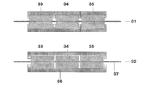
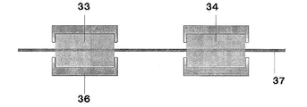
- each heating space may be physically separated (an example is shown in FIG. 7), or a plurality of heating spaces 33, 34 in the same space as shown in FIG. 35 may be provided.
- the inlet, center, and center of the heating space It is also possible to provide a gentle temperature gradient at the outlet.
- the temperature distribution in the heat treatment apparatus can be controlled by devising the arrangement of the heater and the heat insulating material.
- the temperature of heating space means the highest real temperature of the film which passes the heating space.
- the heating space has two or more stages, and the temperature in the heating space differs by two or more stages.
- the upper limit of the number of steps is not particularly limited, but can be, for example, 100 steps or less, and further 50 steps or less.
- the temperature in the subsequent stage is higher than the temperature in the previous stage.
- the temperature of the heating space 2 is higher than the temperature of the heating space 1 in FIG. 3 and the temperature of the heating space 3 is higher than the temperature of the heating space 2.
- the length of one heating space is 5 cm or more, preferably 10 cm or more, more preferably 20 cm or more. If it is 5 cm or more, a sufficient heat history can be added to the continuously passing film.
- a cooling space exists between two heating spaces (between heating spaces) like FIG.
- the cooling space is a space for cooling the film heated in the heating space, and is preferably set to a temperature lower than Tg of the polymer film to be used. Since the carbonized film cooled in the cooling space is harder than the carbonized film heated in the heating space, the carbonized film is hardly deformed in the cooling space. If a cooling space is provided between the heating space and the next heating space, wrinkles are unlikely to occur in the carbonized film. As the number of cooling spaces increases, the effect of suppressing the generation of wrinkles is further obtained. For this reason, it is particularly preferable that the cooling space exists between all the heating spaces.
- a graphite film having a high thermal diffusivity can be obtained from a carbonized film obtained by a continuous carbonization process provided with a cooling space. It is presumed that this is due to the fact that by providing the cooling space, heat treatment can be performed in the subsequent heating space while maintaining the molecular orientation of the carbonized film in the cooling space.
- the temperature of the cooling space of the present invention is lower than the immediately preceding heating space, and is 550 ° C. or less, preferably 500 ° C. or less, more preferably 450 ° C. or less, further 300 ° C. or less, and particularly 100 ° C. or less. It is.
- the temperature of the cooling space means the lowest actual temperature of the film passing through the cooling space.
- the length of the cooling space of the present invention is 5 cm or more, preferably 10 cm or more, more preferably 20 cm or more. If it is 5 cm or more, the continuously passing film can be cooled to the temperature of the cooling space.
- the heat treatment temperature in the second heat treatment apparatus may be the same or different temperature
- the birefringence of the polymer film there is no particular limitation on the birefringence of the polymer film.
- the birefringence is 0.08 or more, carbonization and graphitization of the film easily proceeds, so that a graphite film having a developed graphite layer is easily obtained.
- the birefringence is high.
- the birefringence of the polymer film is preferably 0.08 or more, more preferably 0.10 or more, still more preferably 0.12 or more, and particularly preferably 0.14 or more.
- Birefringence means the difference between the refractive index in an arbitrary direction and the refractive index in the thickness direction in the film plane, and birefringence can be rephrased as birefringence.
- the upper limit of birefringence is not particularly limited, it can be, for example, 0.20 or less, and further 0.18 or less.
- a tension adjusting device for adjusting the tension of the polymer film may be attached before and after the heat treatment device, and heat treatment may be performed while applying tension to the polymer film.
- the tension adjusting device may be provided in all the heat treatment apparatuses, or may be provided only in a part of the heat treatment apparatuses. Examples of the adjusting device for adjusting the tension include a method of applying torque to the rotating shaft of the winding device as shown in FIG.
- tensile strength is added to the polymer film, 5 kgf / cm 2 or more 500 kgf / cm 2 or less, preferably 10 kgf / cm 2 or more 300 kgf / cm 2 or less, More preferably, it is 20 kgf / cm 2 or more and 100 kgf / cm 2 or less.
- the tensile strength is 5 kgf / cm 2 or more, generation of wrinkles accompanying thermal decomposition shrinkage of the film can be suppressed.
- the damage by the excess tension of a film can be prevented as it is 500 kgf / cm ⁇ 2 > or less.
- ⁇ Load applied in the thickness direction of the film> it is preferable to apply a load in the thickness direction of the polymer film in the heating space.
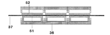
- the method for applying the load is not particularly limited, and as shown in FIG. 5, there is a method in which the polymer film 37 is attached to the hearth 51 and the weight 52 is placed from above.
- the lower limit of the load applied in the thickness direction of the film is 0.1 g / cm 2 or more, preferably 0.5 g / cm 2 or more, more preferably 1 g / cm 2 or more, and the upper limit is 50 g / cm 2 or less, preferably 20 g / cm. cm 2 or less or more preferably is 10 g / cm 2 or less.
- the load is 0.1 g / cm 2 or more, wrinkles associated with thermal decomposition shrinkage of the film can be suppressed. Moreover, the damage of the film by an excessive load can be prevented as it is 50 g / cm ⁇ 2 > or less.
- the film line speed (hereinafter also referred to as line speed) in the continuous carbonization step of the present invention is the film winding speed after heat treatment.
- the line speed is 10 cm / min or more and 500 cm / min or less, preferably 20 cm / min or more and 300 cm / min or less, preferably 30 cm / min or more and 150 cm / min or less.
- a line speed of 10 cm / min or more is preferable from the viewpoint of productivity.
- it is 500 cm / min or less, the uniform heat processing in a heating space is attained, and defects, such as a wrinkle, do not occur easily.
- a method for producing a graphite film including a continuous carbonization process including two or more heating spaces.
- the method for producing a carbonized film of the present invention is expressed as (8) below, and the present invention includes the forms (9) to (14).
- a method for producing a carbonized film including a continuous carbonization process including two or more heating spaces.
- the evaluation criteria are A when the carbonized film does not break even when wound on a paper tube having a diameter of 2 inches, B when it breaks at a diameter of 2 inches but does not break at a diameter of 3 inches, and breaks at a diameter of 3 inches but is 4 inches in diameter.
- the case of not cracking was designated as C, the case of cracking at a diameter of 4 inches, but breaking at 5 inches in diameter, D, and the case of breaking at 5 inches in diameter as E.
- the thermal diffusivity in the surface direction of the graphite film is a sample obtained by cutting the graphite film into a 4 ⁇ 40 mm shape using a thermal diffusivity measuring device (“LaserPit” manufactured by ULVAC-RIKO Co., Ltd.) by an optical alternating current method. Measurement was performed at 10 Hz in an atmosphere of 23 ° C.
- ⁇ Birefringence> The birefringence of the polymer film was measured using a refractive index / film thickness measurement system (model number: 2010 prism coupler) manufactured by Metricon. In the measurement, a light source having a wavelength of 594 nm was used in a 23 ° C. atmosphere, the refractive index was measured in each of the TE mode and the TM mode, and the TE-TM value was measured as birefringence.
- ⁇ Temperature of heating space and cooling space> The temperature of the heating space and the cooling space was measured using a sheath type K thermocouple (manufactured by Yamazato Sangyo Co., Ltd.) with a diameter of 0.5 mm, and the film passing through the heating space and the cooling space was brought into contact with the thermocouple. .
- the temperature of the heating space is the highest temperature of the film passing through the heating space, and the temperature of the cooling space is the lowest temperature of the film passing through the cooling space.
- Example 1 As shown in 41 of FIG. 4, a polyimide film manufactured by Kaneka Corporation having birefringence of 0.14, a thickness of 75 ⁇ m, a width of 200 mm, and a length of 50 m: A roll of apical NPI is set in a rewinding device, and continuously in a heat treatment device. A continuous carbonization process was carried out while feeding. The length of each heating space in the MD direction (Machine Direction: flow direction) is 50 cm, the length in the TD direction (Transverse Direction: width direction) is 300 mm, and each temperature is 550 ° C. so that the temperature in the heating space is uniform.
- the film was conveyed at a line speed of 50 cm / min while applying tension to the film at a tensile strength of 30 kgf / cm 2 .
- the film was sandwiched from above and below with a jig made of graphite as shown in FIG.
- the pressure applied in the thickness direction of the film was adjusted to 2 g / cm 2 . Wrinkles of the obtained carbonized film were evaluated. The results are shown in Tables 1 and 2.
- the carbonized film wound in a roll shape is put into a graphitization furnace so that the TD direction and the vertical direction of the carbonized film coincide with each other as shown in FIG. 6, and up to 2900 ° C. at a rate of 2 ° C./min. Heat treated.
- the obtained film was compressed at a pressure of 10 MPa, and the thermal diffusibility and the bending resistance of the obtained graphite film were evaluated. The results are shown in Tables 1 and 2.
- Example 2 As shown in 42 of FIG. 4, a graphite film was produced in the same manner as in Example 1 except that a cooling space having a length in the MD direction of 50 cm and a temperature adjusted to 25 ° C. was provided between the heating spaces. Various evaluations were made. The results are shown in Tables 1 and 2.
- Example 3 A graphite film was produced in the same manner as in Example 2 except that the temperature of the cooling space was set to 450 ° C., and various evaluations were performed. The results are shown in Tables 1 and 2.
- Example 4 The first three zones of Example 2 are a heating space of 550 ° C., a heating space of 550 ° C., and a heating space of 600 ° C., respectively, and then between each heating space, as shown by 42 in FIG.
- a graphite film was produced in the same manner as in Example 1 except that a cooling space having a length of 50 cm and a temperature adjusted to 550 ° C. was provided, and various evaluations were performed. The results are shown in Tables 1 and 2.
- Example 5 A graphite film was produced in the same manner as in Example 2 except that the heating spaces were adjusted to 550 ° C., 650 ° C., 750 ° C., and 850 ° C., and various evaluations were performed. The results are shown in Tables 1 and 2.
- Example 6 A graphite film was produced in the same manner as in Example 5 except that a heating space of 600 ° C. was provided between the heating spaces of 550 ° C. and 650 ° C., and various evaluations were performed. The results are shown in Tables 1 and 2.
- Example 7 A graphite film was produced in the same manner as in Example 5 except that a heating space of 700 ° C. was provided between the heating spaces of 650 ° C. and 750 ° C., and various evaluations were performed. The results are shown in Tables 1 and 2.
- Example 8 A graphite film was produced in the same manner as in Example 2 except that a heating space of 575 ° C. was provided between the heating spaces of 550 ° C. and 600 ° C., and various evaluations were performed. The results are shown in Tables 1 and 2.
- Example 9 A graphite film was produced in the same manner as in Example 2 except that a heating space of 625 ° C. was provided between the heating spaces of 600 ° C. and 650 ° C., and various evaluations were performed. The results are shown in Tables 1 and 2.
- Example 10 A graphite film was produced in the same manner as in Example 2 except that a heating space of 675 ° C. was provided between the heating spaces of 650 ° C. and 700 ° C., and various evaluations were performed. The results are shown in Tables 1 and 2.
- Example 11 A graphite film was produced in the same manner as in Example 9 except that no pressure was applied in the thickness direction of the film, and various evaluations were performed. The results are shown in Tables 1 and 2.
- Example 12 A graphite film was produced in the same manner as in Example 2 except that the thickness of the polymer film was changed to 50 ⁇ m. The results are shown in Tables 1 and 2.
- Example 13 A graphite film was produced in the same manner as in Example 2 except that the thickness of the polymer film was changed to 125 ⁇ m. The results are shown in Tables 1 and 2.
- Example 14 A polymer film having a low birefringence (birefringence 0.10): A polyimide film manufactured by Kaneka Corporation: A graphite film was produced in the same manner as in Example 2 except that Apical NPI was used. The results are shown in Tables 3 and 4.
- Example 15 In Example 15, POD (polyparaphenylene oxadiazole) was used as the polymer film, and in Example 16, PPV (polyparaphenylene vinylene) was used as the polymer film. A graphite film was produced. The results are shown in Tables 3 and 4.
- Example 17 In Example 17, the width of the polymer film was changed to 50 mm, and in Example 18, a graphite film was produced in the same manner as in Example 2 except that the width of the polymer film was changed to 300 mm. The results are shown in Tables 3 and 4.
- Example 19 Except that Zone 1 was set as a 550 ° C heating space, Zone 2 as a 25 ° C cooling space, Zone 3 as a 750 ° C heating space, Zone 4 as a 25 ° C cooling space, and Zone 5 as a 850 ° C heating space A graphite film was produced in the same manner as in Example 5. The results are shown in Tables 3 and 4.
- Example 20 A graphite film was produced in the same manner as in Example 5 except that the temperature of the heating space in zone 7 was changed from 750 ° C. to 700 ° C., and the continuous carbonization process was completed in zone 7 (zones 8 and 9 were not used). did. The results are shown in Tables 3 and 4.
- Example 21 The temperature of the heating space is changed from 675 ° C. to 700 ° C. in Zone 7, from 700 ° C. to 750 ° C. in Zone 9, from 750 ° C. to 800 ° C. in Zone 11, from 800 ° C. to 850 ° C. in Zone 13, and from Zone 15
- a graphite film was produced in the same manner as in Example 10 except that the temperature was changed from 850 ° C to 1000 ° C. The results are shown in Tables 3 and 4.
- Example 1 A graphite film was produced in the same manner as in Example 1 except that the heating space was set at one stage of 850 ° C., and various evaluations were performed. The results are shown in Tables 3 and 4.
- Examples 1 to 10 are compared with Comparative Example 1.
- the heating space was installed in two or more stages, the generation of wrinkles after continuous carbonization was less than in Comparative Example 1 in which the heating space was one stage, and it was possible to wrap around a paper tube having a smaller diameter. This is because the heating space has two or more stages, so that the amount of shrinkage of the film accompanying thermal decomposition that occurs at once can be reduced, and wrinkles can be suppressed.
- Example 1 and Example 2 are compared.
- Example 2 in which the cooling space was installed the generation of wrinkles after the continuous carbonization process was less than in Example 1 in which the cooling space was not installed. This is because the film cooled in the cooling space becomes hard and difficult to deform.
- Example 2 the thermal diffusivity of the graphite film after graphitization in Example 2 was larger than that in Example 1. This is presumably because the molecular chain disturbance due to excessive thermal decomposition was reset in the cooling space, so that graphitization proceeded easily.
- Example 2 and Example 3 compare Example 2 to Example 4 with different cooling temperatures in the cooling space.
- the temperature of the cooling space is equal to or lower than the hardening temperature of the film
- generation of wrinkles was less than that in Example 4 in which the film could not be hardened.
- the thermal diffusivity after graphitization also improved.
- Example 2 and Example 5 in which the temperature difference between the heating space and the next heating space are different will be compared.
- the temperature difference was 50 ° C.
- the occurrence of wrinkles was less than in Example 5 where the temperature difference was 100 ° C. This is because the amount of shrinkage of the film in one heating space can be made smaller in Example 2 than in Example 5 so that wrinkles are less likely to occur.
- Example 5 Compare Example 5 to Example 7.
- the temperature range of 600 ° C. or more and 700 ° C. or less is preferably 50 ° C. intervals, which is better to reduce the temperature difference between the heating spaces, the occurrence of wrinkles is less than that in which the other regions are spaced at 50 ° C. It was found effective to reduce the temperature difference in this region.
- Example 2 and Examples 8 to 10 are compared.
- Example 9 in which the temperature range of 600 ° C. to 650 ° C. was set at intervals of 25 ° C., the generation of wrinkles was extremely small, and it was found that reducing the temperature difference was particularly effective in this range.
- Example 1 Compared with Comparative Example 1 with a weight reduction rate of 40%, Examples 1 to 10 with a maximum weight reduction rate of 25% or less showed less wrinkling. Comparing Example 2 and Examples 5 to 10 in which a cooling space of 25 ° C. was installed between the temperature spaces, Example 9 with the maximum weight reduction rate of 11% had the least wrinkle generation. Subsequently, 16 to 20% of Example 2, Example 6, Example 8, and Example 10 were less prone to wrinkles, and 24% of Example 5 and Example 7 were most prone to wrinkles. From this result, it was found that the generation of wrinkles can be suppressed by reducing the amount of thermal decomposition at once and the film shrinking.
- Example 12 in which the thickness of the polymer film is 50 ⁇ m and Example 13 in which the thickness of the polymer film is 125 ⁇ m, it was found that a carbonized film with reduced wrinkles can be obtained without problems even when the thickness is 50 ⁇ m to 125 ⁇ m. . Further, from the comparison between Examples 12 and 13, the thinner the polymer film, the higher the thermal diffusivity of the graphite film.
- Example 17 the result of the wrinkle (winding test) after the continuous carbonization step is A, the result of Example 18 is C, and a carbonized film with reduced wrinkles is obtained, and the polymer film is narrow. When was used, a carbonized film in which wrinkles were further suppressed was obtained. From Examples 17 and 18, it can be seen that the carbonized film can be obtained without problems when the width of the polymer film is 50 mm to 300 mm.
- Example 19 where the heating temperature difference between zones 1 and 2 was as wide as 200 ° C., the weight retention of the polymer film after passing through the heating space of zone 1 was 97%, and the weight reduction rate was 3%. . On the other hand, the weight retention of the polymer film after passing through the heating space of zone 3 was 65%, and the weight reduction rate was 32%. The difference in weight reduction rate between zones 1 and 3 is 29%.
- the result of the wrinkle (winding test) after the continuous carbonization process is D.
- the carbonized film of the present invention A carbonized film with a low degree of wrinkle suppression was obtained.
- Example 21 ⁇ Maximum temperature of heating space> From the comparison of Examples 5 and 21, the temperature was gradually increased, and in Example 21 where the maximum temperature of the heating space was low, the carbonized film was less likely to be wrinkled. ) was good with A.
- Example 10 the temperature of the heating space in zone 15 which is the maximum temperature is 850 ° C. and 1000 ° C., and the result of wrinkles (winding test) after the continuous carbonization step is that in Example 10 B, Example 21 was C. From this, it can be seen that the lower the maximum temperature of the heating region, the less the occurrence of wrinkles in the carbonized film, and the higher the higher the temperature in the carbonized film. Further, Example 10 having a lower maximum temperature resulted in a higher thermal diffusivity of the graphite film.
Landscapes
- Chemical & Material Sciences (AREA)
- Engineering & Computer Science (AREA)
- Ceramic Engineering (AREA)
- Organic Chemistry (AREA)
- Manufacturing & Machinery (AREA)
- Materials Engineering (AREA)
- Structural Engineering (AREA)
- Inorganic Chemistry (AREA)
- Life Sciences & Earth Sciences (AREA)
- General Life Sciences & Earth Sciences (AREA)
- Geology (AREA)
- Carbon And Carbon Compounds (AREA)
Abstract
Description
本発明の連続炭化工程は、高分子フィルムの熱分解開始温度以上、高分子フィルムの熱分解終了温度未満の温度範囲で実施することが好ましい。高分子フィルムの熱分解開始温度以上、高分子フィルムの熱分解終了温度未満の温度範囲で高分子フィルムを熱分解するために、この領域を2段階以上で熱処理することでシワや割れの発生を抑制することができる。また、2段階以上で熱処理することで黒鉛化後のグラファイトフィルムの熱拡散率も高くなり易い。
2段階以上の加熱空間の好ましい温度範囲は、500℃以上1000℃未満、好ましくは500℃以上900℃以下、更に好ましくは550℃以上850℃以下、更には550℃以上800℃以下、特には550℃以上700℃以下であるとよい。500℃以上1000℃未満において、高分子フィルムの熱分解に伴う収縮が起き易い、この領域を2段階以上で熱処理することでシワや割れの発生を抑制することができる。また、2段階以上で熱処理することで黒鉛化後のグラファイトフィルムの熱拡散率も高くなり易い。
高分子フィルムの収縮の大きな500℃以上1000℃未満の温度範囲においては、段階数を増やして、各加熱空間の温度とその次に続く加熱空間(以下、近接する加熱空間という)の温度との温度差(後段の温度と前段の温度との温度差)ができるだけ小さくなるようにすると、シワや割れなど更に発生し難くなる。近接する加熱空間の温度差は5℃以上200℃以下、好ましくは10℃以上100℃以下、更に好ましくは20℃以上50℃以下であるとよい。5℃以上であれば、熱処理に伴うフィルムの破損や伸びを抑制することができる。また、加熱空間の数を減らすことができるために好ましい。また、200℃以下であれば、炭化フィルムの一度に収縮する量を小さくできるのでシワが発生し難い。さらに、200℃以下であれば、黒鉛化後のグラファイトフィルムの熱拡散率も高くなり易い。
一つの加熱空間の入口直前のフィルム重量と当該加熱空間の出口直後のフィルム重量から算出されるフィルムの重量減少率(以下、各加熱空間通過前後の重量減少率という)が、25%以下、好ましくは20%以下、更に好ましくは15%以下となるように加熱空間の段階数や温度設定を決定するとよい。25%以下になるようにすると、フィルムの収縮を緩やかにでき、シワが発生し難い。また、25%以下であれば、黒鉛化後のグラファイトフィルムの熱拡散率も高くなり易い。
重量減少率(%)=(加熱空間の入口直前のフィルム重量-加熱空間の出口直後のフィルム重量)/高分子フィルムの初期重量×100)
上記高分子フィルムの初期重量とは、高分子フィルムを熱処理する前、23℃を保持した雰囲気下で24時間放置後、23℃で測定した高分子フィルムの重量である。また、加熱空間の入口直前のフィルム重量とは、加熱空間の入口直前で取り出したフィルムを、23℃を保持した雰囲気下で24時間放置後、23℃で測定したフィルムの重量であり、加熱空間の出口直後のフィルム重量とは、加熱空間の出口直後で取り出したフィルムを、23℃を保持した雰囲気下で24時間放置後、23℃で測定したフィルムの重量である。
重量保持率(%)=(1-(高分子フィルムの初期重量-所定加熱空間の出口直後の高分子フィルム重量)/高分子フィルムの初期重量)×100)
<グラファイトフィルム>
グラファイトフィルムは、原料フィルムである高分子フィルムを熱処理することにより製造できる。グラファイトフィルムの製造に適した高分子フィルムとして、ポリイミドフィルム、ポリアミドフィルム、ポリオキサジアゾールフィルム、ポリベンゾチアゾールフィルム、ポリベンゾビスアゾールフィルム、ポリベンゾオキサゾールフィルム、ポリベンゾビスオキサゾールフィルム、ポリパラフェニレンビニレンフィルム、ポリベンゾイミダゾールフィルム、ポリベンゾビスイミダゾールフィルム、ポリチアゾールフィルムのうちから選択された少なくとも一種類以上の高分子フィルムを例示できる。
高分子フィルムからグラファイトフィルムを得る製造方法の一例として、炭化工程、黒鉛化工程、加圧処理工程を実施する方法が挙げられる。炭化工程では、出発物質であるフィルムを減圧下もしくは不活性ガス中で加熱処理して炭化する。すなわち、炭化工程では炭化フィルムが熱処理対象物である(炭化工程では、炭化フィルムを熱処理する)。
この炭化工程は、通常1000℃程度の温度にてバッチ式で加熱処理を行う。例えば、室温から10℃/分昇温速度で予備加熱処理を行った場合には、1000℃の温度領域で30分程度の温度保持を行う加熱処理が望ましい。加熱処理の段階では、フィルムの配向性が失われないように面方向の圧力を加えてもよい。
本発明のグラファイトフィルムの製造方法は、連続炭化工程を含む。連続炭化工程は炭化工程において、図2のように長尺の高分子フィルム23を加熱処理装置21へ連続的に供給しながら連続焼成する工程(以下、連続加熱プロセスともいう)である。その際、加熱処装置の前後に巻き替え装置を設置して、高分子フィルムを搬送してもよい。また、連続炭化工程は、窒素やアルゴンなどの不活性ガス中で行うことが好ましい。
本発明の加熱空間とは、高分子フィルムを熱処理するために設けた、図2のような加熱処理装置21の内部の空間である。複数の加熱空間を設ける場合には、各加熱空間は空間を物理的に切り分けてもよいし(その一例を図7に示す)、図3のように同じ空間内に複数の加熱空間33、34、35を設けてもかまわない。高分子フィルムに対して均一に熱を与えるために、一つの加熱空間内の温度分布は均一に保つことが好ましいが、急激な温度変化を避けるために、加熱空間の入口と中央部、中央部と出口において、緩やかな温度勾配をつけることも可能である。ヒーターや断熱材の配置を工夫し、加熱処理装置内の温度分布を制御することができる。なお、加熱空間の温度とは、その加熱空間を通過するフィルムの最も高い実温度を意味する。
本発明の連続炭化工程は、図4のように2つの加熱空間の間(加熱空間同士の間)に冷却空間が存在することが好ましい。冷却空間とは、加熱空間で加熱されたフィルムを冷却するための空間であり、使用する高分子フィルムのTgよりも低い温度に設定されていることが好ましい。冷却空間で冷却された炭化フィルムは加熱空間で加熱されている炭化フィルムに比べて硬くなるために、冷却空間では炭化フィルムは変形し難い。加熱空間と次の加熱空間の間に冷却空間を設けると、炭化フィルムにシワが発生し難くなる。冷却空間の数は多いほど、シワの発生を抑制する効果がより得られる。そのため、加熱空間同士の間の全てに冷却空間が存在することが特に好ましい。
本発明において、高分子フィルムの複屈折について特に制限はない。しかし、複屈折が0.08以上であればフィルムの炭化、黒鉛化が進行し易くなるので、グラファイト層が発達したグラファイトフィルムが得られ易くなる。特に、本発明のように高分子フィルムの配向性が崩れ易い連続炭化工程を実施する場合には複屈折が高い方が好ましい。高分子フィルムの複屈折は好ましくは0.08以上、より好ましくは0.10以上、さらに好ましくは0.12以上、特に好ましくは0.14以上である。なお、複屈折とはフィルム面内の任意方向の屈折率と厚み方向の屈折率との差を意味し、複屈折を複屈折率と換言することができる。複屈折の上限値は特に限定されないが、例えば、0.20以下、さらに0.18以下とすることができる。
本発明の連続炭化工程において、例えば加熱処理装置の前後に高分子フィルムの張力を調整するための張力調整装置が取り付けて、高分子フィルムに張力を加えながら熱処理してもよい。張力調整装置はすべての加熱処理装置に設けてもよいし、一部の加熱処理装置にのみ設けてもよい。張力を調整するための調整装置として、図2のような巻取り装置の回転軸にトルクを加える方法などが挙げられる。
本発明の連続炭化工程において、加熱空間にて高分子フィルムの厚み方向に荷重を加えることが好ましい。荷重を加える方法として、特に限定しないが、図5のように、炉床51に高分子フィルム37を添わせ、上から重石52を載せる方法などが挙げられる。フィルムの厚み方向に加える荷重は、下限が0.1g/cm2以上、好ましくは0.5g/cm2以上、さらに好ましくは1g/cm2以上、上限が50g/cm2以下、好ましくは20g/cm2以下、さらに好ましくは10g/cm2以下であるとよい。荷重が0.1g/cm2以上であると、フィルムの熱分解収縮に伴うシワを抑制することができる。また、50g/cm2以下であると、過剰荷重によるフィルムの破損を防ぐことができる。
本発明の連続炭化工程におけるフィルムのライン速度(以下、ライン速度ともいう)とは、熱処理後のフィルムの巻き取り速度である。ライン速度は、10cm/min以上500cm/min以下、好ましくは20cm/min以上300cm/min以下、好ましくは30cm/min以上150cm/min以下である。ライン速度が10cm/min以上が生産性の観点から好ましい。また、500cm/min以下であれば、加熱空間での均一な熱処理が可能となり、シワなどの不良が発生し難い。
<連続炭化工程後のシワ(巻取りテスト)>
連続炭化工程後の炭化フィルムのシワを評価した。シワの評価は、23℃の雰囲気下、炭化フィルムを各種径の紙管に5周巻きつけて、割れるかどうかを確認した。シワが多いものほど、紙管に巻きつけると割れ易く、小さな径の紙管には巻きつけることができない。
グラファイトフィルムの面方向の熱拡散率は、光交流法による熱拡散率測定装置(アルバック理工(株)社製「LaserPit」)を用いて、グラファイトフィルムを4×40mmの形状に切り取ったサンプルを、23℃の雰囲気下、10Hzにて測定した。
高分子フィルムの複屈折は、メトリコン社製の屈折率・膜厚測定システム(型番:2010 プリズムカプラ)を使用して測定した。測定は、23℃の雰囲気下、波長594nmの光源を用い、TEモードとTMモードでそれぞれ屈折率を測定し、TE-TMの値を複屈折として測定した。
加熱空間及冷却空間の温度は、φ0.5mmのシース型K熱電対(山里産業製)を使用して、加熱空間及冷却空間を通過するフィルムと熱電対を接触させ、フィルム実温度を測定した。加熱空間の温度とは、その加熱空間を通過するフィルムの最も高い温度、冷却空間の温度とは、その冷却空間を通過するフィルムの最も低い温度とした。
図4の41のように、複屈折0.14、厚み75μm、幅200mm、長さ50mの株式会社カネカ製ポリイミドフィルム:アピカルNPIの巻き物を巻き替え装置にセットし、加熱処理装置に連続的に供給しながら連続炭化工程を実施した。各加熱空間のMD方向(Machine Direction:流れ方向)の長さは50cm、TD方向(Transverse Direction:幅方向)の長さは300mmとし、加熱空間内の温度が均一になるように、それぞれ550℃、600℃、650℃、700℃、750℃、800℃、850℃に調整した。フィルムに対して引張り強さ30kgf/cm2で張力を加えながら、50cm/minのライン速度でフィルムを搬送した。各空間内は図5のように黒鉛製の冶具でフィルムを上下から挟みこみ、間を滑らせるように搬送した。フィルムの厚み方向に加わる圧力は2g/cm2に調整した。得られた炭化フィルムのシワの評価を行った。結果を表1、2に示す。
図4の42のように、各加熱空間の間に、MD方向の長さが50cmで温度が25℃に調整された冷却空間を設けたこと以外は実施例1と同様にグラファイトフィルムを製造し、各種評価を行った。結果を表1、2に示す。
冷却空間の温度を450℃に設定したこと以外は実施例2と同様にグラファイトフィルムを製造し、各種評価を行った。結果を表1、2に示す。
実施例2の最初の3ゾーンが、それぞれ550℃の加熱空間、550℃の加熱空間、600℃の加熱空間であり、その後、図4の42のように、各加熱空間の間に、MD方向の長さが50cmで温度が550℃に調整された冷却空間を設けたこと以外は実施例1と同様にグラファイトフィルムを製造し、各種評価を行った。結果を表1、2に示す。
加熱空間をそれぞれ550℃、650℃、750℃、850℃に調整した以外は実施例2と同様にグラファイトフィルムを製造し、各種評価を行った。結果を表1、2に示す。
550℃と650℃の加熱空間の間に600℃の加熱空間を設けたこと以外は実施例5と同様にグラファイトフィルムを製造し、各種評価を行った。結果を表1、2に示す。
650℃と750℃の加熱空間の間に700℃の加熱空間を設けたこと以外は実施例5と同様にグラファイトフィルムを製造し、各種評価を行った。結果を表1、2に示す。
550℃と600℃の加熱空間の間に575℃の加熱空間を設けたこと以外は実施例2と同様にグラファイトフィルムを製造し、各種評価を行った。結果を表1、2に示す。
600℃と650℃の加熱空間の間に625℃の加熱空間を設けたこと以外は実施例2と同様にグラファイトフィルムを製造し、各種評価を行った。結果を表1、2に示す。
650℃と700℃の加熱空間の間に675℃の加熱空間を設けたこと以外は実施例2と同様にグラファイトフィルムを製造し、各種評価を行った。結果を表1、2に示す。
フィルムの厚み方向に圧力を加えなかったこと以外は実施例9と同様にグラファイトフィルムを製造し、各種評価を行った。結果を表1、2に示す。
高分子フィルムの厚みを50μmに変更したこと以外は、実施例2と同様にしてグラファイトフィルムを製造した。結果を表1、2に示す。
高分子フィルムの厚みを125μmに変更したこと以外は、実施例2と同様にしてグラファイトフィルムを製造した。結果を表1、2に示す。
複屈折が低い(複屈折0.10)高分子フィルム:株式会社カネカ製ポリイミドフィルム:アピカルNPIを使用した以外は、実施例2と同様にしてグラファイトフィルムを製造した。結果を表3、4に示す。
実施例15では、高分子フィルムとしてPOD(ポリパラフェニレンオキサジアゾール)を用い、実施例16では、高分子フィルムとしてPPV(ポリパラフェニレンビニレン)を用いた以外は、実施例2と同様にしてグラファイトフィルムを製造した。結果を表3、4に示す。
実施例17では、高分子フィルムの幅を50mmに変更し、実施例18では、高分子フィルムの幅を300mmに変更したこと以外は、実施例2と同様にしてグラファイトフィルムを製造した。結果を表3、4に示す。
ゾーン1を550℃の加熱空間、ゾーン2を25℃の冷却空間、ゾーン3を750℃の加熱空間、ゾーン4を25℃の冷却空間、ゾーン5を850℃の加熱空間に設定したこと以外は、実施例5とどうようにしてグラファイトフィルムを製造した。結果を表3、4に示す。
ゾーン7の加熱空間の温度を750℃から700℃に変更し、ゾーン7で連続炭化工程を終了した(ゾーン8、9を用いない)こと以外は、実施例5と同様にしてグラファイトフィルムを製造した。結果を表3、4に示す。
加熱空間の温度を、ゾーン7では675℃から700℃に、ゾーン9では700℃から750℃に、ゾーン11では750℃から800℃に、ゾーン13では、800℃から850℃に、ゾーン15では850℃から1000℃に変更した以外は、実施例10と同様にしてグラファイトフィルムを製造した。結果を表3、4に示す。
加熱空間を850℃の1段階としたこと以外は、実施例1と同様にグラファイトフィルムを製造し、各種評価を行った。結果を表3、4に示す。
比較例2では、ゾーン1の加熱空間の温度を850℃から1000℃に変更し、比較例3では、ゾーン1の加熱空間の温度を850℃から800℃に変更した以外は、比較例1と同様にしてグラファイトフィルムを製造した。結果を表3、4に示す。
特開平4-149013公報の実施例1を追試した。
特開2004-299937公報の実施例2を追試した。
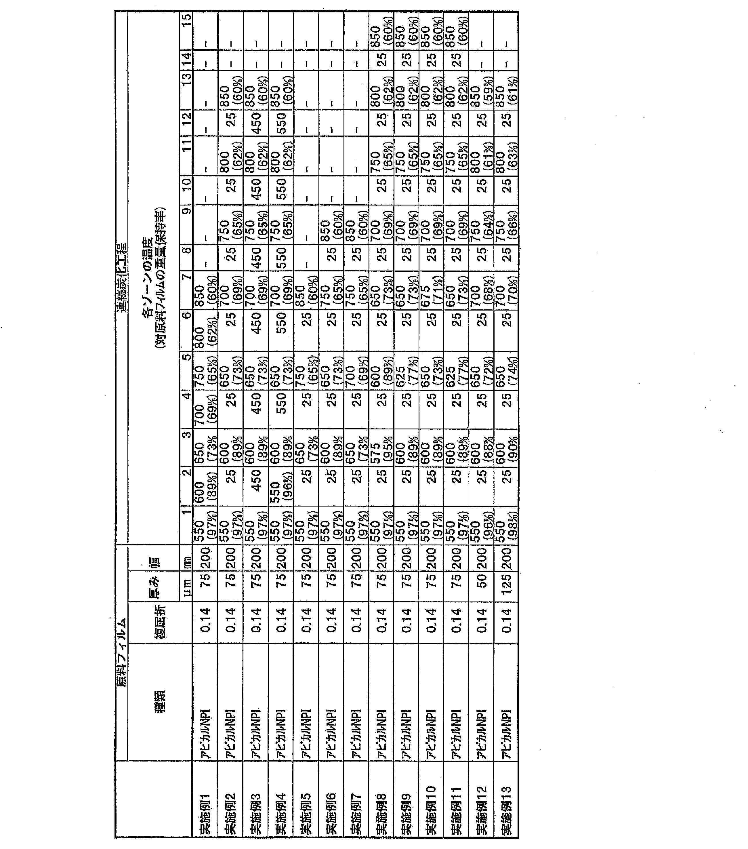
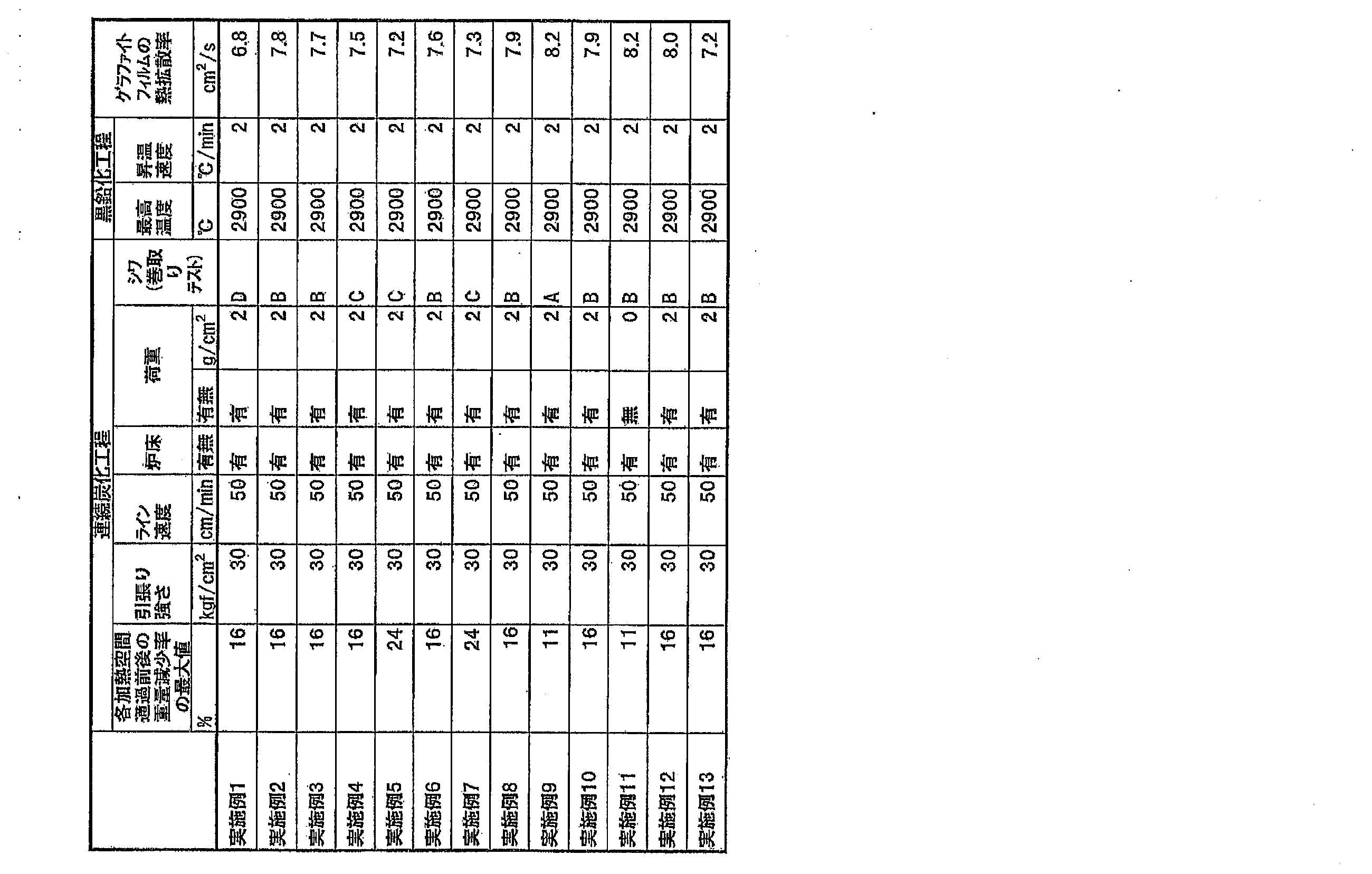


実施例1~10と比較例1を比較する。加熱空間を2段階以上設置した実施例1~10は、加熱空間が一段階の比較例1より連続炭化後のシワの発生が少なく、より小さな径の紙管に巻きつけることができた。これは、加熱空間が2段階以上あることで、一度に起きる熱分解に伴うフィルムの収縮量を小さくでき、シワを抑制することができた。
実施例1と実施例2を比較する。冷却空間を設置した実施例2は、冷却空間を設置していない実施例1と比較して連続炭化工程後のシワの発生が少なかった。これは、冷却空間で冷却されたフィルムは硬質化し変形し難くなるためである。
加熱空間と次の加熱空間の温度差の異なる実施例2と実施例5を比較する。温度差が50℃の実施例2は、温度差が100℃の実施例5と比較して、シワの発生が少なかった。これは、実施例5より実施例2の方が、1つの加熱空間でフィルムが収縮する量を小さくできるのでシワが発生し難かったことが理由である。
重量減少率が40%の比較例1より、重量減少率が最大で25%以下の実施例1~実施例10はシワの発生が少なかった。25℃の冷却空間を各温度空間の間に設置した、実施例2、実施例5~実施例10を比較すると、重量減少率の最大値が11%の実施例9がシワの発生が最も少なく、続いて16~20%の実施例2、実施例6、実施例8、実施例10はシワが発生し難く、24%の実施例5、実施例7は最もシワが発生し易かった。この結果から、一度に熱分解し、フィルムが収縮する量を小さくすることで、シワの発生を抑制できることがわかった。
フィルムの厚み方向に圧力を加える実施例9と加えなかった実施例11を比較すると、圧力を加えた実施例9の方がシワの発生が少なかった。
高分子フィルムの厚みが50μmの実施例12および高分子フィルムの厚みが125μmの実施例13から、厚みが50μm~125μmの場合にもシワが抑制された炭化フィルムが問題なく得られることが分かった。また、実施例12、13の比較から、高分子フィルムが薄い方が、グラファイトフィルムの熱拡散率が高い結果となった。
実施例2、14の比較から、複屈折が低い高分子フィルムを用いた場合であっても、シワが抑制された炭化フィルムが問題なく得られることが分かった。ただし、高分子フィルムの複屈折が低い実施例14では、グラファイトフィルムの熱拡散率が低い結果となった。
実施例15、16の結果から高分子フィルムとしてPODまたはPPVを用いた場合であっても、シワが抑制された炭化フィルムが問題なく得られることが分かった。ただし、実施例2、15、16の比較から高分子フィルムとしてポリイミドフィルムを用いた場合に、最も熱拡散率の高いグラファイトフィルムが得られる結果となった。
実施例17では、連続炭化工程後のシワ(巻取りテスト)の結果がAであり、実施例18の結果はCであり、シワの抑制された炭化フィルムが得られ、幅が狭い高分子フィルムを用いた場合、シワがより抑制された炭化フィルムが得られた。実施例17、18から、高分子フィルムの幅を50mm~300mmとした場合に問題なく炭化フィルムが得られることが分かる。
ゾーン1、2の加熱温度差が200℃と広い実施例19では、ゾーン1の加熱空間を通過した後の高分子フィルムの重量保持率は97%であり、重量減少率は3%であった。一方、ゾーン3の加熱空間を通過した後の高分子フィルムの重量保持率は65%であり、重量減少率は32%であった。ゾーン1、3の重量減少率の差は29%であり、高分子フィルムが急速に収縮した結果、連続炭化工程後のシワ(巻取りテスト)の結果はDであり、本発明の炭化フィルムとしてはシワの抑制度合いが低い炭化フィルムが得られた。
実施例5、21の比較から、温度の上昇を緩やかに行い、加熱空間の最高温度が低い実施例21の方が、炭化フィルムにシワが発生し難く、連続炭化工程後のシワ(巻取りテスト)の結果はAと良好であった。
21 加熱処理装置
22 巻き替え装置
23 熱処理前の高分子フィルム
24 熱処理後の高分子フィルム
31 空間を物理的に切り分けた加熱空間
32 空間を物理的に切り分けていない加熱空間
33 加熱空間1
34 加熱空間2
35 加熱空間3
36 炉体
37 高分子フィルム
41 冷却空間を設定しない場合
42 冷却空間を設定した場合
43 冷却空間
51 炉床
52 重石
61 炭化フィルムの巻物
62 炉床
63 重力方向
Claims (14)
- 2段階以上の加熱空間を含む連続炭化工程を含む、グラファイトフィルムの製造方法。
- 前記加熱空間の温度は、高分子フィルムの熱分解開始温度以上、高分子フィルムの熱分解終了温度未満の範囲にあることを特徴とする請求項1に記載のグラファイトフィルムの製造方法。
- 前記連続炭化工程において、少なくとも2段階以上の加熱空間の温度が、500℃以上1000℃未満の範囲にあることを特徴とする請求項1または2に記載のグラファイトフィルムの製造方法。
- 前記連続炭化工程に少なくとも1つの冷却空間が存在することを特徴とする請求項1~3のいずれかに記載のグラファイトフィルムの製造方法。
- 近接する加熱空間の温度差が5℃以上200℃以下の範囲であることを特徴とする請求項1~4のいずれかに記載のグラファイトフィルムの製造方法。
- 各加熱空間通過前後のフィルムの重量減少率が25%以下であることを特徴とする請求項1~5のいずれかに記載のグラファイトフィルムの製造方法。
- 連続炭化工程に使用する高分子フィルムの複屈折が0.10以上であることを特徴とする請求項1~6のいずれかに記載のグラファイトフィルムの製造方法。
- 2段階以上の加熱空間を含む連続炭化工程を含む、炭化フィルムの製造方法。
- 前記加熱空間の温度は、高分子フィルムの熱分解開始温度以上、高分子フィルムの熱分解終了温度未満の範囲にあることを特徴とする請求項8に記載の炭化フィルムの製造方法。
- 前記連続炭化工程において、少なくとも2段階以上の加熱空間の温度が、500℃以上1000℃未満の範囲にあることを特徴とする請求項8または9に記載の炭化フィルムの製造方法。
- 前記連続炭化工程に少なくとも1つの冷却空間が存在することを特徴とする請求項8~10のいずれかに記載の炭化フィルムの製造方法。
- 近接する加熱空間の温度差が5℃以上200℃以下の範囲であることを特徴とする請求項8~11のいずれかに記載の炭化フィルムの製造方法。
- 各加熱空間通過前後のフィルムの重量減少率が25%以下であることを特徴とする請求項8~12のいずれかに記載の炭化フィルムの製造方法。
- 連続炭化工程に使用する高分子フィルムの複屈折が0.10以上であることを特徴とする請求項8~13のいずれかに記載の炭化フィルムの製造方法。
Priority Applications (4)
| Application Number | Priority Date | Filing Date | Title |
|---|---|---|---|
| US14/005,423 US8999286B2 (en) | 2011-03-18 | 2012-03-15 | Method for producing graphite film and method for producing carbonized film |
| CN201280011528.8A CN103547530B (zh) | 2011-03-18 | 2012-03-15 | 石墨膜的制造方法及碳化膜的制造方法 |
| KR1020137022060A KR101611317B1 (ko) | 2011-03-18 | 2012-03-15 | 그라파이트 필름의 제조 방법 및 탄화 필름의 제조 방법 |
| JP2013505938A JP5422778B2 (ja) | 2011-03-18 | 2012-03-15 | グラファイトフィルムの製造方法および炭化フィルムの製造方法 |
Applications Claiming Priority (2)
| Application Number | Priority Date | Filing Date | Title |
|---|---|---|---|
| JP2011-061495 | 2011-03-18 | ||
| JP2011061495 | 2011-03-18 |
Publications (1)
| Publication Number | Publication Date |
|---|---|
| WO2012128187A1 true WO2012128187A1 (ja) | 2012-09-27 |
Family
ID=46879337
Family Applications (1)
| Application Number | Title | Priority Date | Filing Date |
|---|---|---|---|
| PCT/JP2012/056778 Ceased WO2012128187A1 (ja) | 2011-03-18 | 2012-03-15 | グラファイトフィルムの製造方法および炭化フィルムの製造方法 |
Country Status (7)
| Country | Link |
|---|---|
| US (1) | US8999286B2 (ja) |
| JP (4) | JP5422778B2 (ja) |
| KR (1) | KR101611317B1 (ja) |
| CN (1) | CN103547530B (ja) |
| MY (1) | MY161760A (ja) |
| TW (1) | TWI529127B (ja) |
| WO (1) | WO2012128187A1 (ja) |
Cited By (3)
| Publication number | Priority date | Publication date | Assignee | Title |
|---|---|---|---|---|
| WO2014046187A1 (ja) * | 2012-09-19 | 2014-03-27 | 株式会社カネカ | 炭素質フィルムの製造方法、及びグラファイトフィルムの製造方法 |
| JP2015178423A (ja) * | 2014-03-18 | 2015-10-08 | 株式会社カネカ | 炭素質フィルムの製造方法及びグラファイトフィルムの製造方法 |
| US9221683B1 (en) * | 2014-08-27 | 2015-12-29 | Guardnec Co., Ltd. | Method for preparing graphite film |
Families Citing this family (6)
| Publication number | Priority date | Publication date | Assignee | Title |
|---|---|---|---|---|
| JP6307883B2 (ja) | 2014-01-07 | 2018-04-11 | 日本精工株式会社 | 転がり軸受 |
| KR101512831B1 (ko) * | 2014-08-27 | 2015-04-20 | 가드넥(주) | 롤타입 그라파이트 필름 제조용 지그 및 이를 이용한 그라파이트 필름 제조 방법 |
| KR101826855B1 (ko) * | 2016-03-31 | 2018-03-22 | 한국화학연구원 | 흑연 시트의 제조 방법 |
| KR102151508B1 (ko) * | 2018-11-16 | 2020-09-03 | 피아이첨단소재 주식회사 | 고후도 그라파이트 시트의 제조방법 및 이를 이용하여 제조된 고후도 그라파이트 시트 |
| JPWO2023080047A1 (ja) * | 2021-11-02 | 2023-05-11 | ||
| CN114804081A (zh) * | 2022-04-21 | 2022-07-29 | 广州大学 | 一种激光分级碳化聚酰亚胺膜制备石墨烯膜的设备及方法 |
Citations (2)
| Publication number | Priority date | Publication date | Assignee | Title |
|---|---|---|---|---|
| JP2002033107A (ja) * | 2000-07-18 | 2002-01-31 | Ube Ind Ltd | 燃料電池用セパレータ |
| JP2004299937A (ja) * | 2003-03-28 | 2004-10-28 | Kanegafuchi Chem Ind Co Ltd | グラファイトフィルムの製造方法 |
Family Cites Families (15)
| Publication number | Priority date | Publication date | Assignee | Title |
|---|---|---|---|---|
| US3528774A (en) * | 1967-03-14 | 1970-09-15 | Us Air Force | Formation of high modulus,high strength graphite yarns |
| US4005183A (en) * | 1972-03-30 | 1977-01-25 | Union Carbide Corporation | High modulus, high strength carbon fibers produced from mesophase pitch |
| JP2976481B2 (ja) * | 1989-05-10 | 1999-11-10 | 松下電器産業株式会社 | フィルム状グラファイトの製造方法 |
| JP3041934B2 (ja) | 1990-10-11 | 2000-05-15 | 松下電器産業株式会社 | グラファイトフィルムの製造方法 |
| JP2000178016A (ja) * | 1998-12-11 | 2000-06-27 | Matsushita Electric Ind Co Ltd | グラファイトシートの製造方法及びグラファイトシートを用いた熱伝導体 |
| JP4189569B2 (ja) | 2001-11-29 | 2008-12-03 | 東レ・デュポン株式会社 | 炭素フィルムの製造方法 |
| JP4078630B2 (ja) * | 2001-11-29 | 2008-04-23 | 東レ・デュポン株式会社 | 炭素フィルムの製造方法及びそれによって得られる炭素フィルム |
| JP4119693B2 (ja) * | 2002-06-17 | 2008-07-16 | 株式会社カネカ | 絶縁材付グラファイトフィルムおよびその製造方法 |
| JP4324399B2 (ja) * | 2003-03-28 | 2009-09-02 | 株式会社カネカ | グラファイトフィルム及びポリイミドフィルム |
| JP5252617B2 (ja) * | 2006-09-04 | 2013-07-31 | 国立大学法人 筑波大学 | フィルム状炭素材料を製造する方法およびフィルム状炭素材料 |
| JP2008254937A (ja) * | 2007-03-30 | 2008-10-23 | Ube Ind Ltd | 目的とする形状の炭素質フィルムを得るための製造方法 |
| JP5340646B2 (ja) * | 2008-06-06 | 2013-11-13 | 株式会社カネカ | グラファイトフィルムの製造方法 |
| JP5322587B2 (ja) | 2008-08-12 | 2013-10-23 | 株式会社カネカ | グラファイトフィルムの製造方法 |
| JP5434163B2 (ja) * | 2009-03-16 | 2014-03-05 | パナソニック株式会社 | グラファイトシートの製造方法 |
| JP4684353B2 (ja) * | 2010-03-05 | 2011-05-18 | 株式会社カネカ | フィルム状グラファイト |
-
2012
- 2012-03-15 WO PCT/JP2012/056778 patent/WO2012128187A1/ja not_active Ceased
- 2012-03-15 KR KR1020137022060A patent/KR101611317B1/ko active Active
- 2012-03-15 JP JP2013505938A patent/JP5422778B2/ja active Active
- 2012-03-15 CN CN201280011528.8A patent/CN103547530B/zh active Active
- 2012-03-15 MY MYPI2013701451A patent/MY161760A/en unknown
- 2012-03-15 US US14/005,423 patent/US8999286B2/en active Active
- 2012-03-16 TW TW101109197A patent/TWI529127B/zh active
-
2013
- 2013-09-30 JP JP2013205637A patent/JP5575964B2/ja active Active
- 2013-12-25 JP JP2013267948A patent/JP5576550B2/ja active Active
-
2014
- 2014-07-02 JP JP2014137085A patent/JP5655171B2/ja active Active
Patent Citations (2)
| Publication number | Priority date | Publication date | Assignee | Title |
|---|---|---|---|---|
| JP2002033107A (ja) * | 2000-07-18 | 2002-01-31 | Ube Ind Ltd | 燃料電池用セパレータ |
| JP2004299937A (ja) * | 2003-03-28 | 2004-10-28 | Kanegafuchi Chem Ind Co Ltd | グラファイトフィルムの製造方法 |
Cited By (6)
| Publication number | Priority date | Publication date | Assignee | Title |
|---|---|---|---|---|
| WO2014046187A1 (ja) * | 2012-09-19 | 2014-03-27 | 株式会社カネカ | 炭素質フィルムの製造方法、及びグラファイトフィルムの製造方法 |
| JPWO2014046187A1 (ja) * | 2012-09-19 | 2016-08-18 | 株式会社カネカ | 炭素質フィルムの製造方法、及びグラファイトフィルムの製造方法 |
| US9868639B2 (en) | 2012-09-19 | 2018-01-16 | Kaneka Corporation | Method for manufacturing carbonaceous film and method for manufacturing graphite film |
| JP2015178423A (ja) * | 2014-03-18 | 2015-10-08 | 株式会社カネカ | 炭素質フィルムの製造方法及びグラファイトフィルムの製造方法 |
| US9221683B1 (en) * | 2014-08-27 | 2015-12-29 | Guardnec Co., Ltd. | Method for preparing graphite film |
| US9527739B2 (en) | 2014-08-27 | 2016-12-27 | Guardnec Co., Ltd. | Method for preparing graphite film |
Also Published As
| Publication number | Publication date |
|---|---|
| JP5576550B2 (ja) | 2014-08-20 |
| JPWO2012128187A1 (ja) | 2014-07-24 |
| CN103547530A (zh) | 2014-01-29 |
| JP5655171B2 (ja) | 2015-01-14 |
| KR101611317B1 (ko) | 2016-04-11 |
| CN103547530B (zh) | 2016-06-22 |
| MY161760A (en) | 2017-05-15 |
| JP2014001139A (ja) | 2014-01-09 |
| JP5422778B2 (ja) | 2014-02-19 |
| JP2014177402A (ja) | 2014-09-25 |
| TWI529127B (zh) | 2016-04-11 |
| TW201245039A (en) | 2012-11-16 |
| JP2014129227A (ja) | 2014-07-10 |
| JP5575964B2 (ja) | 2014-08-20 |
| US8999286B2 (en) | 2015-04-07 |
| KR20140005267A (ko) | 2014-01-14 |
| US20140004033A1 (en) | 2014-01-02 |
Similar Documents
| Publication | Publication Date | Title |
|---|---|---|
| JP5655171B2 (ja) | グラファイトフィルムの製造方法および炭化フィルムの製造方法 | |
| JP5512035B1 (ja) | グラファイトフィルムの製造方法 | |
| US9776927B2 (en) | Graphite film | |
| JP5624695B2 (ja) | 炭素質フィルムの製造方法、及びグラファイトフィルムの製造方法 | |
| JP5519883B1 (ja) | グラファイトフィルム及びグラファイトフィルムの製造方法 | |
| JP2004299937A (ja) | グラファイトフィルムの製造方法 | |
| US10501594B2 (en) | Graphite film and method for producing graphite film | |
| JP6345281B2 (ja) | 反応及び統合用超伝導体の製造方法及びシステム | |
| JP6368509B2 (ja) | 炭素質フィルムの製造方法及びグラファイトフィルムの製造方法 | |
| JP6739003B2 (ja) | グラファイトとその製造方法 | |
| JP2019534840A (ja) | ガラスペインを曲げ加工するための方法 |
Legal Events
| Date | Code | Title | Description |
|---|---|---|---|
| 121 | Ep: the epo has been informed by wipo that ep was designated in this application |
Ref document number: 12761322 Country of ref document: EP Kind code of ref document: A1 |
|
| ENP | Entry into the national phase |
Ref document number: 2013505938 Country of ref document: JP Kind code of ref document: A |
|
| ENP | Entry into the national phase |
Ref document number: 20137022060 Country of ref document: KR Kind code of ref document: A |
|
| WWE | Wipo information: entry into national phase |
Ref document number: 14005423 Country of ref document: US |
|
| NENP | Non-entry into the national phase |
Ref country code: DE |
|
| 122 | Ep: pct application non-entry in european phase |
Ref document number: 12761322 Country of ref document: EP Kind code of ref document: A1 |