WO2012127999A1 - 制御装置および燃料電池システム - Google Patents
制御装置および燃料電池システム Download PDFInfo
- Publication number
- WO2012127999A1 WO2012127999A1 PCT/JP2012/054939 JP2012054939W WO2012127999A1 WO 2012127999 A1 WO2012127999 A1 WO 2012127999A1 JP 2012054939 W JP2012054939 W JP 2012054939W WO 2012127999 A1 WO2012127999 A1 WO 2012127999A1
- Authority
- WO
- WIPO (PCT)
- Prior art keywords
- electrode
- fuel cell
- current value
- current
- unit
- Prior art date
- Legal status (The legal status is an assumption and is not a legal conclusion. Google has not performed a legal analysis and makes no representation as to the accuracy of the status listed.)
- Ceased
Links
Images


Classifications
-
- H—ELECTRICITY
- H01—ELECTRIC ELEMENTS
- H01M—PROCESSES OR MEANS, e.g. BATTERIES, FOR THE DIRECT CONVERSION OF CHEMICAL ENERGY INTO ELECTRICAL ENERGY
- H01M8/00—Fuel cells; Manufacture thereof
- H01M8/04—Auxiliary arrangements, e.g. for control of pressure or for circulation of fluids
- H01M8/04298—Processes for controlling fuel cells or fuel cell systems
- H01M8/04694—Processes for controlling fuel cells or fuel cell systems characterised by variables to be controlled
- H01M8/04858—Electric variables
- H01M8/04895—Current
- H01M8/0491—Current of fuel cell stacks
-
- H—ELECTRICITY
- H01—ELECTRIC ELEMENTS
- H01M—PROCESSES OR MEANS, e.g. BATTERIES, FOR THE DIRECT CONVERSION OF CHEMICAL ENERGY INTO ELECTRICAL ENERGY
- H01M8/00—Fuel cells; Manufacture thereof
- H01M8/04—Auxiliary arrangements, e.g. for control of pressure or for circulation of fluids
- H01M8/04298—Processes for controlling fuel cells or fuel cell systems
- H01M8/04313—Processes for controlling fuel cells or fuel cell systems characterised by the detection or assessment of variables; characterised by the detection or assessment of failure or abnormal function
- H01M8/04537—Electric variables
- H01M8/04574—Current
- H01M8/04589—Current of fuel cell stacks
-
- H—ELECTRICITY
- H01—ELECTRIC ELEMENTS
- H01M—PROCESSES OR MEANS, e.g. BATTERIES, FOR THE DIRECT CONVERSION OF CHEMICAL ENERGY INTO ELECTRICAL ENERGY
- H01M8/00—Fuel cells; Manufacture thereof
- H01M8/08—Fuel cells with aqueous electrolytes
- H01M8/083—Alkaline fuel cells
-
- Y—GENERAL TAGGING OF NEW TECHNOLOGICAL DEVELOPMENTS; GENERAL TAGGING OF CROSS-SECTIONAL TECHNOLOGIES SPANNING OVER SEVERAL SECTIONS OF THE IPC; TECHNICAL SUBJECTS COVERED BY FORMER USPC CROSS-REFERENCE ART COLLECTIONS [XRACs] AND DIGESTS
- Y02—TECHNOLOGIES OR APPLICATIONS FOR MITIGATION OR ADAPTATION AGAINST CLIMATE CHANGE
- Y02E—REDUCTION OF GREENHOUSE GAS [GHG] EMISSIONS, RELATED TO ENERGY GENERATION, TRANSMISSION OR DISTRIBUTION
- Y02E60/00—Enabling technologies; Technologies with a potential or indirect contribution to GHG emissions mitigation
- Y02E60/30—Hydrogen technology
- Y02E60/50—Fuel cells
Definitions
- the present invention relates to a fuel cell control device capable of operating a fuel cell with high power generation efficiency and a fuel cell system using the same.
- the fuel cell includes a membrane electrode assembly (MEA) having a configuration in which an electrolyte membrane is sandwiched between an anode and a cathode as a main part of power generation.
- MEA membrane electrode assembly
- a polymer electrolyte fuel cell (direct fuel) Battery) phosphoric acid fuel cell, molten carbonate fuel cell, solid oxide fuel cell, alkaline fuel cell and the like.
- the alkaline fuel cell is a fuel cell in which an anion conductive electrolyte membrane (anion exchange membrane) is used as an electrolyte membrane, and charge carriers are hydroxide ions (OH ⁇ ).
- anion exchange membrane anion exchange membrane
- charge carriers are hydroxide ions (OH ⁇ ).
- the supplied reducing agent (fuel), for example, H 2 gas and OH ⁇ transmitted from the cathode electrode are expressed by the following formula (2):
- Alkaline fuel cells have advantages such as fewer restrictions on constituent materials such as catalysts and can be manufactured at a lower cost, but unlike other fuel cells, the electrolyte of the electrolyte membrane and catalyst layer is an anion conductive electrolyte. Therefore, the electrolyte membrane and the catalyst layer absorb carbon dioxide (CO 2 ) in the environment, and OH ⁇ in the electrolyte membrane and the catalyst layer is represented by the following formulas (3) and (4): CO 2 + 2OH ⁇ ⁇ CO 3 2 ⁇ + H 2 O (3) CO 2 + OH - ⁇ HCO 3 - (4) It has an inherent problem that it is easily replaced by CO 3 2 ⁇ and / or HCO 3 ⁇ (hereinafter sometimes referred to as “CO 2 -derived anion”) by such a reaction.
- CO 2 + 2OH ⁇ ⁇ CO 3 2 ⁇ + H 2 O CO 2 + OH - ⁇ HCO 3 - (4)
- Non-Patent Document 1 It is known that the problem of increase in cell resistance can be improved by a phenomenon called “self-purge” caused by operation of an alkaline fuel cell [for example, Hiroyuki Yanagi, and Kenji Fukuta, ECS Transactions, 16 (2), 257- 262 (2008) (Non-Patent Document 1)].
- “Self-purge” refers to the cause of a decrease in anion conductivity due to the operation of an alkaline fuel cell.
- the CO 2 -derived anion contained in the electrolyte membrane and the catalyst layer moves to the anode electrode and is reduced by the reducing agent. This refers to the phenomenon of being discharged from the anode electrode as two gases.
- the following formulas (5) and (6): H 2 + CO 3 2 ⁇ ⁇ CO 2 + H 2 O + 2e ⁇ (5) H 2 + 2HCO 3 ⁇ ⁇ 2CO 2 + 2H 2 O + 2e ⁇ (6) Can be expressed as
- the power generation amount of the fuel cell is adjusted according to the power consumption of the electronic device using the fuel cell as a power source.
- the power generation amount that is, the operating current value
- the present invention has been made in view of the above problems, and an object of the present invention is to provide a fuel cell control device capable of operating a fuel cell with high power generation efficiency and a fuel cell system using the same.
- the present invention is connected to a detection unit for detecting the state of the fuel cell, a current value changing unit for changing a current value flowing through the membrane electrode assembly of the fuel cell, a detection unit and a current value changing unit.
- a control device is provided that includes a control unit for controlling the current value changing unit so that a current equal to or greater than a predetermined current value A flows through the membrane electrode assembly for a certain period of time according to the detection result of the detection unit.
- the fuel cell is preferably an alkaline fuel cell comprising a membrane electrode assembly having an anion conductive electrolyte membrane as an electrolyte membrane.
- the predetermined current value A is in the range of 600 to 1000 mA / cm 2 , for example.
- the detection unit preferably detects a ratio T 1 / T 0 of time T 1 during which a current equal to or greater than a predetermined current value A flows through the membrane electrode assembly within unit time T 0 .
- the current value changing unit may include at least an electronic load device or a variable resistor connected to the alkaline fuel cell. Further, the current value changing unit may include an electronic load device or a variable resistor connected to the alkaline fuel cell and a power supply device connected in series to the alkaline fuel cell.
- the membrane electrode assembly includes an anion conductive electrolyte membrane, a first electrode laminated on the first surface of the anion conductive electrolyte membrane, and a first surface of the anion conductive electrolyte membrane.
- the detection unit has a time during which a current of a predetermined current value A or more flows between the first electrode and the second electrode within the unit time T 0 . is used to detect the ratio T 1 / T 0 of T 1, the current value changing unit is for changing the current flowing between the first electrode and the second electrode, the control unit, the detection unit According to the detection result, the current value changing unit is controlled so that a current of a predetermined current value A or more flows between the first electrode and the second electrode for a predetermined time.
- the first electrode may be an anode electrode during power generation
- the second electrode may be a cathode electrode during power generation.
- the membrane electrode assembly includes an anion conductive electrolyte membrane, a first electrode laminated on the first surface of the anion conductive electrolyte membrane, and a first surface of the anion conductive electrolyte membrane.
- the second electrode is stacked on the second surface opposite to the first electrode, and the third electrode is stacked on the first surface spaced apart from the first electrode.
- the detection unit includes the first electrode within the unit time T 0 .
- the ratio T 1 / T 0 of the time T 1 during which a current greater than or equal to the predetermined current value A flows between the first electrode and the second electrode is detected.
- the control unit is configured to change a current value that flows between the third electrode and the second electrode according to a detection result of the detection unit so that a current greater than or equal to a predetermined current value A flows for a certain period of time.
- the value changing unit is controlled.
- the first electrode can be an anode electrode during power generation
- the second electrode can be a cathode electrode during power generation.
- the membrane electrode assembly includes an anion conductive electrolyte membrane, a first electrode laminated on a first surface of the anion conductive electrolyte membrane, and a first of the anion conductive electrolyte membrane.
- a second electrode stacked on the second surface facing the surface; a third electrode stacked on the first surface spaced apart from the first electrode; and a second electrode stacked on the second surface spaced apart from the second electrode.
- the detection unit detects the ratio T 1 / T 0 of the time T 1 during which a current of a predetermined current value A or more flows between the first electrode and the second electrode within the unit time T 0 .
- the current value changing unit changes a current value flowing between the third electrode and the fourth electrode, and the control unit changes the third electrode and the second electrode according to the detection result by the detecting unit.
- the current value changing unit is controlled so that a current of a predetermined current value A or more flows between the four electrodes for a predetermined time.
- the first electrode can be an anode electrode during power generation
- the second electrode can be a cathode electrode during power generation.
- the volume of the catalyst layer of the first electrode as the anode electrode is also preferable to make the volume of the catalyst layer of the second electrode larger than the volume of the catalyst layer of the second electrode as the cathode electrode.
- the present invention also provides a fuel cell system comprising a fuel cell unit including the fuel cell and a control device according to the present invention.
- the fuel cell can be operated with high power generation efficiency.
- FIG. 10 is a schematic sectional view taken along line XX shown in FIG. 9.
- FIG. 10 is a schematic cross-sectional view taken along line XI-XI shown in FIG. 9.
- FIG. 13 is a schematic sectional view taken along line XIII-XIII shown in FIG. 12. It is a schematic sectional drawing in the XIV-XIV line
- FIG. 18 is a schematic sectional view taken along line XVIII-XVIII shown in FIG.
- FIG. 18 is a schematic sectional view taken along line XIX-XIX shown in FIG. 17.
- FIG. 18 is a schematic sectional view taken along line XX-XX shown in FIG.
- FIG. 18 is a schematic sectional view taken along line XXI-XXI shown in FIG. 17.
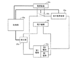
- FIG. 1 is a schematic diagram showing a configuration of a control device according to the present invention and a fuel cell system to which the control device is applied.
- the control device of the present invention is connected to a fuel cell unit 10 (fuel cell) including a fuel cell, and a detection unit 20 for detecting the state of the fuel cell;
- a current value changing unit 30 for changing a current value of a current flowing through the membrane electrode assembly of the fuel cell; and a control unit connected to the detecting unit 20 and the current value changing unit 30 40 is basically provided.
- the control unit 40 receives a detection result (information signal) related to the state of the fuel cell from the detection unit 20, and according to the received detection result, a current of a predetermined current value A or more flows through the membrane electrode assembly for a certain period of time.
- the current value changing unit 30 is controlled.
- the fuel cell system of the present invention includes a fuel cell unit 10 including a fuel cell; a detection unit 20 connected to the fuel cell unit 10 (fuel cell) and detecting the state of the fuel cell; A current value changing unit 30 for changing a current value of a current flowing through the membrane electrode assembly of the fuel cell; and a control unit connected to the detecting unit 20 and the current value changing unit 30 40 is basically provided.
- the fuel cell constituting the fuel cell unit 10 is preferably an alkaline fuel cell including a membrane electrode assembly having an anion conductive electrolyte membrane.
- the control device of the present invention controls the fuel cell so that a current of a predetermined current value A or more flows through the membrane electrode assembly of the fuel cell for a “certain time”.
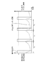
- FIG. 2 is a conceptual diagram showing a state in which a cycle in which a current of a predetermined current value A or more flows for a certain period of time within a unit time is repeated in the fuel cell membrane electrode assembly.
- a current of a predetermined current value A or more flows through the membrane electrode assembly for a certain period of time means that the fuel cell supplies power to an electronic device using this as a power source.
- a current equal to or greater than the predetermined current value A flows for a certain period of time within the unit time T 0 regardless of whether or not the power is being generated (that is, whether or not power is being generated).
- a cycle of unit time T 0 including a certain time during which a current of a predetermined current value A or more flows is repeated.
- a cycle of unit time T 0 including a certain time during which a current of a predetermined current value A or more is flowing is repeated two or more times, all the above certain times may have the same time length, or two or more kinds Different time lengths may be included.
- the current passed through the membrane electrode assembly is not particularly limited as long as it is equal to or greater than the predetermined current value A, and may all be the same current value or may include two or more different current values.
- a current greater than or equal to the predetermined current value A may be supplied a plurality of times within the unit time T 0 .
- the self-purge is repeated by repeating the cycle of the unit time T 0 including a certain time during which a current of a predetermined current value A or more flows, the CO 2 -derived anion concentration in the membrane electrode complex Can be maintained in a substantially low state, and accumulation of CO 2 -derived anions can be suppressed.
- the problems of an increase in cell resistance and an increase in reaction overvoltage at the anode electrode are improved, and the power generation efficiency of the alkaline fuel cell can be improved.
- FIG. 3 shows only one unit time T 0 including a certain time during which a current of a predetermined current value A or more flows through the membrane electrode assembly of an alkaline fuel cell (a current of a predetermined current value A or more is It shows conceptually how the CO 2 -derived anion concentration changes when it flows only once).
- a current of a predetermined current value A or more flows through the membrane electrode assembly for a certain period of time includes a case where the current of a predetermined current value A or more flows as shown in FIG. Although there may be a case where there is only one unit time T 0 , such a cycle of unit time T 0 is preferably repeated as shown in FIG. This is because the CO 2 -derived anion concentration in the membrane electrode complex can be maintained substantially always low.
- T 0 including a certain time during which a current equal to or greater than the predetermined current value A flows, sufficiently high power generation efficiency is obtained when the fuel cell generates power after the unit time T 0. There is a risk of not being able to.
- a current of a predetermined current value A or more flows. There may be only one unit time T 0 including a certain time.
- control device of the present invention and the fuel cell system (particularly an alkaline fuel cell system) to which the control device is applied can have the following operational effects.
- the CO 2 -derived anion concentration in the membrane electrode assembly can be maintained in a state that is always kept low, so that a fuel cell (alkaline fuel cell) can be generated in a state in which an increase in cell resistance and an increase in reaction overvoltage at the anode electrode are suppressed. Can be improved.
- the surplus power (power exceeding the amount required by the electronic device) is compared with the case where the operating current value is continuously increased. ) Can be suppressed. This also contributes to the improvement of power generation efficiency.
- the surplus power may be stored in, for example, a storage battery (not shown).
- the state of the fuel cell” detected by the detection unit 20 refers to an index (parameter) that can evaluate the CO 2 -derived anion concentration in the membrane electrode assembly.
- Specific examples of the battery include the following.
- [A] is in the unit time T in 0, the ratio T 1 / T 0 of the time predetermined current value A or more current flows through the membrane electrode assembly T 1, [B] CO 2 -derived anion concentration (or CO 3 2 ⁇ concentration of these) in the anion conductive electrolyte membrane, [C] pH of the anion conductive electrolyte membrane, [D] resistance value of the anion conductive electrolyte membrane, [E] Output voltage value of alkaline fuel cell.
- the detection unit 20 detects [a] because it is an index that affects the CO 2 -derived anion concentration in the membrane electrode complex and the detection method is relatively easy. It is preferable.
- control device for controlling an alkaline fuel cell and an alkaline fuel cell system to which the control device is applied, and detects the above [a] as the state of the alkaline fuel cell.
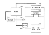
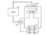
- FIG. 4 is a schematic diagram showing a control device according to the present embodiment and an alkaline fuel cell system to which the control device is applied.
- the control device and the alkali are connected to an electronic device (electronic device 50) to which power is supplied.
- 1 shows the configuration of a fuel cell system.
- the control device according to the present embodiment includes the above-described detection unit 20 connected to a fuel cell unit 10a as a fuel cell unit 10 including an alkaline fuel cell including a membrane electrode assembly having an anion conductive electrolyte membrane.
- Detection unit 20a for detecting (a ratio T 1 / T 0 of time T 1 in which a current equal to or greater than a predetermined current value A flows in the membrane electrode assembly within a certain unit time T 0 ); connected to the fuel cell unit 10a And an electronic load device 30a for changing the current value of the current flowing through the membrane electrode assembly of the alkaline fuel cell as the current value changing unit 30 connected in parallel to the electronic device 50; and
- the electronic load device 30a is connected to the detection unit 20a and the electronic load device 30a, and the electronic load device 30a is controlled so that a current of a predetermined current value A or more flows through the membrane electrode assembly for a predetermined time according to the detection result by the detection unit 20a.
- a control unit 40a is provided.
- the fuel cell unit 10a is illustrated in a form showing only the first electrode (for example, the anode electrode) and the second electrode (for example, the cathode electrode) of the membrane electrode assembly included in the alkaline fuel cell.
- first electrode for example, the anode electrode
- second electrode for example, the cathode electrode
- the alkaline fuel cell of the fuel cell unit can take.
- the detection unit 20a is a fuel cell unit for measuring a current value flowing through the membrane electrode assembly (more specifically, a current value flowing between the first electrode and the second electrode of the membrane electrode assembly). At least an ammeter connected to 10a (alkaline fuel cell) is provided, and together with this ammeter, a unit time T 0 and a time T 1 when a current of a predetermined current value A or more flows through the membrane electrode assembly are measured.
- Time measuring means such as a timer
- storage means such as a memory
- the time measuring means and the storage means can be included in the control unit 40a.
- the controller 40a is not particularly limited as long as it can control the electronic load device 30a so that a current equal to or greater than the predetermined current value A flows through the membrane electrode assembly for a certain period of time according to the detection result by the detector 20a.
- it can be a personal computer.
- the detection unit 20a preferably detects the time ratio T 1 / T 0 at all times, and the control unit 40a determines that the time ratio T 1 / T 0 is less than the predetermined time ratio W T.
- the control unit 40a applies the predetermined current value A to the membrane electrode assembly (between the first electrode and the second electrode) regardless of whether the fuel cell unit 10a is generating power (supplying power to the electronic device 50).
- the electronic load device 30a is controlled so that the above current flows for a certain period of time (for example, a current waveform pattern as shown in FIG. 2 is obtained).
- the control unit 40a determines that the time ratio T 1 / T 0 is less than the predetermined time ratio W T , a reducing agent is supplied to the first electrode and an oxidizing agent is supplied to the second electrode.
- a predetermined time T 2 such that T 2 / T 0 ⁇ W T is established between the first electrode and the second electrode.
- a current greater than A is supplied.
- the time ratio T 1 / T 0 is constantly detected so that a cycle of unit time T 0 including a certain time during which a current of a predetermined current value A or more flows is repeated.
- the fuel cell unit 10a performs power generation (power supply to the electronic device 50) in order to achieve a substantially always low CO 2 -derived anion concentration
- the control unit 40a is forced to exceed the predetermined current value A according to the control flow.
- the CO 2 -derived anion is substantially always low. Concentration is realized.
- the unit time T 0 is not particularly limited, and can be, for example, in the range of about 10 to 30 minutes.
- the predetermined time ratio W T is determined in consideration of a desired degree of improvement in power generation efficiency and a degree of improvement in start-up time, and can be selected from a range of 5 to 20% (for example, 10%), for example.
- the predetermined current value A is also determined in consideration of the desired degree of improvement in power generation efficiency and the degree of start-up time, and is selected from a range of 400 to 1000 mA / cm 2 , preferably 600 to 1000 mA / cm 2. be able to.
- the current value (both the current value detected by the detection unit and the current value of the current that flows for a certain period of time (T 2 )) in the present invention refers to a membrane electrode assembly (first electrode-second electrode in this embodiment).
- the value of “current greater than or equal to the predetermined current value A” that is passed through the membrane electrode assembly for a certain time (time length T 2 ) according to the detection result by the detection unit 20a is detected by the detection unit 20a as “unit time T 0.
- T 2 is normally set to be longer than T 1 .
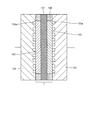
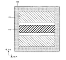
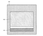
- FIG. 5 is a schematic cross-sectional view showing an example of an alkaline fuel cell that can be provided in the fuel cell unit 10a in the present embodiment.
- the alkaline fuel cell shown in FIG. 5 includes an anion conductive electrolyte membrane 101, a first electrode (anode electrode) 103 laminated on the first surface of the anion conductive electrolyte membrane 101, and a first of the anion conductive electrolyte membrane 101.
- a membrane electrode assembly (MEA) 1 composed of a second electrode (cathode electrode) 102 laminated on a second surface facing the surface is provided.
- the first electrode 103 and the second electrode 102 are provided so as to face each other with the anion conductive electrolyte membrane 101 interposed therebetween.
- a gasket 106 (for example, a layer made of an elastic resin such as silicone rubber or a cured resin layer of a curable resin such as an epoxy resin) is provided at the periphery of the electrode to prevent intrusion of air or the like from the electrode end face. Is provided.
- the alkaline fuel cell shown in FIG. 5 includes a first current collecting layer 105 laminated on the first electrode 103 and a second current collecting layer 104 laminated on the second electrode 102. These current collecting layers are members for exchanging electrons with an electrode in contact with the current collecting layer and for performing electrical wiring.
- the first current collecting layer 105 is provided with a first flow path 105 a for supplying a reducing agent to the first electrode 103.
- the second current collection layer 104 is provided with a second flow path 104 a for supplying an oxidant to the second electrode 102.
- each current collecting layer is also a member for supplying a reducing agent and an oxidizing agent.
- the anion-conducting electrolyte membrane 101 has an electrical insulation property in order to conduct OH - ions and prevent a short circuit between the first electrode 103 and the second electrode 102. Although it does not restrict
- Preferred examples of the anion conductive solid polymer electrolyte membrane include, for example, perfluorosulfonic acid, perfluorocarboxylic acid, styrene vinylbenzene, and quaternary ammonium solid polymer electrolyte membranes (anion exchange membranes). .
- a membrane obtained by impregnating polyacrylic acid with a concentrated potassium hydroxide solution or an anion conductive solid oxide electrolyte membrane can also be used as the anion conductive electrolyte membrane 101.
- the anion conductive electrolyte membrane 101 preferably has an anion conductivity of 10 ⁇ 5 S / cm or more, and an electrolyte membrane having an anion conductivity of 10 ⁇ 3 S / cm or more such as a perfluorosulfonic acid polymer electrolyte membrane. It is more preferable to use
- the thickness of the anion conductive electrolyte membrane 101 is usually 5 to 300 ⁇ m, preferably 10 to 200 ⁇ m.
- the second electrode 102 functioning as a cathode electrode during power generation is provided with at least a catalyst layer composed of a porous layer containing a catalyst and an electrolyte. These catalyst layers are laminated in contact with the surface of the anion conductive electrolyte membrane 101.
- the catalyst (anode catalyst) of the first electrode 103 catalyzes a reaction that generates water and electrons from the reducing agent and OH ⁇ supplied to the first electrode 103.
- the electrolyte of the first electrode 103 has a function of conducting OH ⁇ conducted from the anion conductive electrolyte membrane 101 to the catalytic reaction site.
- the catalyst (cathode catalyst) of the second electrode 102 catalyzes the reaction of generating OH ⁇ from the oxidant and water supplied to the second electrode 102 and the electrons transferred from the first electrode 103.
- the electrolyte of the second electrode 102 has a function of conducting the generated OH ⁇ to the anion conductive electrolyte membrane 101.
- anode catalyst and the cathode catalyst conventionally known ones can be used.
- the alloy is preferably an alloy containing at least two of platinum, iron, cobalt, and nickel.
- the anode catalyst and the cathode catalyst may be the same or different.
- the anode catalyst and the cathode catalyst are preferably those supported on a carrier, preferably a conductive carrier.
- a carrier preferably a conductive carrier.
- the conductive carrier include carbon black such as acetylene black, furnace black, channel black, and ketjen black, and conductive carbon particles such as graphite and activated carbon.
- carbon fibers such as vapor grown carbon fiber (VGCF), carbon nanotube, carbon nanowire, and the like can be used.
- the same electrolyte as that constituting the anion conductive solid polymer electrolyte membrane can be used.
- the content ratio of the catalyst to the electrolyte in each catalyst layer is usually 5/1 to 1/4, and preferably 3/1 to 1/3, based on weight.
- the first electrode 103 and the second electrode 102 may each include a gas diffusion layer laminated on the catalyst layer.
- the gas diffusion layer has a function of diffusing the supplied reducing agent or oxidizing agent in the surface and also has a function of transferring electrons to and from the catalyst layer.
- the gas diffusion layer can be a porous layer having electrical conductivity. Specifically, for example, carbon paper; carbon cloth; epoxy resin film containing carbon particles; metal or alloy foam, sintered body Or it can be a fiber nonwoven fabric.
- the thickness of the gas diffusion layer is preferably 10 ⁇ m or more in order to reduce the diffusion resistance of the reducing agent or oxidizing agent in the direction perpendicular to the thickness direction (in-plane direction), and the diffusion resistance in the thickness direction. In order to reduce this, it is preferable that it is 1 mm or less.
- the thickness of the gas diffusion layer is more preferably 100 to 500 ⁇ m.
- the first current collecting layer 105 and the second current collecting layer 104 are provided on and in contact with the first electrode 103 and the second electrode 102, respectively, and exchange electrons with the contacting electrodes. It is a member for performing electrical wiring. Further, in the alkaline fuel cell shown in FIG. 5, these current collecting layers also have a function of supplying a reducing agent and an oxidizing agent, and the first current collecting layer 105 is provided with a reducing agent in the first electrode 103.
- the second current collecting layer 104 is provided with a second flow path 104 a for supplying an oxidant to the second electrode 102.
- the material of the current collecting layer is not particularly limited, and for example, conductive materials such as carbon materials, conductive polymers, various metals, and alloys typified by stainless steel can be used.
- the material of each current collecting layer may be the same or different.
- the first flow path 105a and the second flow path 104a can be composed of one or more grooves provided on the electrode-side surface of the current collecting layer, and the shape thereof is not particularly limited, and is linear or serpentine Etc.
- a separate member (channel plate) for supplying the reducing agent and the oxidizing agent may be laminated on the current collecting layer.
- the flow path plate may be one in which one or more grooves are provided on the surface of a plate-like body made of a non-conductive material such as various plastic materials.
- H 2 gas for example, H 2 gas, hydrocarbon gas, alcohol, ammonia gas and the like can be used, and it is preferable to use H 2 gas.
- oxidizing agent for example, O 2 gas or a gas containing O 2 such as air can be used, and air is preferably used. The same applies to other alkaline fuel cells exemplified in this specification.
- an alkaline fuel cell as shown in FIG. 6 may be used.
- the alkaline fuel cell shown in FIG. 6 is characterized by including the membrane electrode assembly 2, and the membrane electrode assembly 2 has a volume of the catalyst layer (anode catalyst layer) of the first electrode 103 as the second electrode. It is characterized in that the weight of the anode catalyst contained in the anode catalyst layer is made larger than the weight of the cathode catalyst contained in the cathode catalyst layer by making it larger than the volume of the catalyst layer (cathode catalyst layer) 102 has.
- the (5) and for the speed of the CO 2 gas emissions from Serufupaji as shown in (6) becomes larger, it is possible to lower the CO 2 from the anion concentration in the electrolyte membrane and the catalyst layer more quickly become able to.
- the area of the anode catalyst layer is made larger.
- Increasing the area and thickness of the anode catalyst layer is advantageous from the viewpoint of improving the durability of the anode catalyst layer.
- FIG. 6 shows an example in which the area of the anode catalyst layer is larger than that of the cathode catalyst layer.
- the fuel cell unit 10a and the electronic device 50 may be connected via a converter (step-up circuit).
- a converter step-up circuit
- FIG. 7 is a schematic diagram showing a control device according to the present embodiment and an alkaline fuel cell system to which the control device is applied.
- the control device and the alkali are connected to an electronic device (electronic device 50) to which power is supplied.
- 1 shows the configuration of a fuel cell system.
- the control device and alkaline fuel cell system of this embodiment are the same as those of the first embodiment, except that the current value changing unit 30 further includes a power supply device 30c in addition to the electronic load device 30a.
- the power supply device 30c is connected in series to the alkaline fuel cell of the fuel cell unit 10a via the switch 30b.
- the switch 30b plays a role of switching between the presence / absence of the power supply device 30c in the circuit connecting the electronic load device 30a and the fuel cell unit 10a.
- the control unit 40a operates the switch 30b to connect the power supply device 30c and the fuel cell unit 10a in series. Further, in some cases, the electromotive force of the power supply device 30c is increased and the electronic load device 30a flows. By increasing the load current, a current of a predetermined current value A or more is caused to flow between the first electrode and the second electrode for a certain time T 2 such that T 2 / T 0 ⁇ W T.
- the time ratio T 1 / T 0 is constantly detected so that a cycle of unit time T 0 including a certain time during which a current of a predetermined current value A or more flows is repeated.
- a primary battery such as an alkaline battery or a manganese battery
- a secondary battery such as a lithium ion battery, a lithium polymer battery, a nickel hydride battery, or a lead storage battery
- a direct current stabilized power supply can be used.
- the electromotive force of the power supply device can be adjusted, so that controllability of the current flowing through the membrane electrode assembly is improved.
- FIG. 8 is a schematic diagram showing a control device according to the present embodiment and an alkaline fuel cell system to which the control device is applied.
- the control device and the alkali are connected to an electronic device (electronic device 50) to which power is supplied.
- 1 shows the configuration of a fuel cell system.
- the control device and alkaline fuel cell system of the present embodiment have a membrane electrode assembly that further includes a third electrode on the first electrode side in addition to the first electrode as the anode electrode and the second electrode as the cathode electrode.
- the present embodiment is the same as the first embodiment except that an alkaline fuel cell is used for the fuel cell portion 10a.
- the third electrode is a self-purge electrode provided independently of the first electrode and the second electrode, and is the surface of the anion conductive electrolyte membrane on the same side as the first electrode that functions as an anode electrode during power generation. However, they are arranged apart from (not in contact with) the first electrode.
- the unit time T in 0, the membrane electrode assembly - the ratio T 1 / T 0 (the first electrode second inter-electrode) to the time flows over the current predetermined current value A T 1 is predetermined
- the control unit 40a determines whether the time ratio is less than the time ratio W T , the control unit 40a determines whether the fuel cell unit 10a is generating power (supplying electric power to the electronic device 50) or not.
- the electronic load device 30a is controlled so that a current of a predetermined current value A or more flows between the third electrode and the second electrode for a predetermined time.
- the control unit 40a determines that the time ratio T 1 / T 0 is less than the predetermined time ratio W T , a reducing agent is supplied to the third electrode and an oxidizing agent is supplied to the second electrode.
- a predetermined time T 2 such that T 2 / T 0 ⁇ W T is obtained between the third electrode and the second electrode.
- a current greater than A is supplied.
- the time ratio T 1 / T 0 is constantly detected so that a cycle of unit time T 0 including a certain time during which a current of a predetermined current value A or more flows is repeated.
- the value of the current that flows for a certain time (T 2 ) here is a value obtained by dividing the amount of current flowing between the third electrode and the second electrode by the projected area of the cathode electrode (second electrode) onto the electrolyte membrane. And can be selected from the range of 400 to 1000 mA / cm 2 , preferably 600 to 1000 mA / cm 2 .
- the present embodiment is different from the first embodiment in that a current of a predetermined current value A or more flows between the third electrode (for self-purging) and the second electrode (cathode electrode) for a certain period of time. Is different.
- the predetermined current value A between the first electrode and the second electrode is used.
- the concentration of CO 2 -derived anions in the membrane electrode composite can be maintained at a substantially low level.
- a third electrode for self-purging is provided independently of the first electrode, and the ratio T 1 / T 0 of the time T 1 during which a current of a predetermined current value A or more flows between the first electrode and the second electrode is a predetermined time.
- the ratio is less than W T
- the accumulation of CO 2 -derived anions is increased. Since it occurs at three electrodes, it is possible to prevent an increase in reaction overvoltage at the first electrode that functions as an anode during power generation, and it is possible to further improve power generation efficiency.
- the electronic load device 30a is connected to the third electrode and the second electrode so that a current of a predetermined current value A or more can flow between the third electrode and the second electrode of the membrane electrode assembly for a predetermined time.
- the first electrode and the second electrode that contribute to substantial power generation are connected to the electronic device 50 using a wiring that is different from the wiring that connects the third electrode and the second electrode to the electronic load device 30a (see FIG. 8).
- An ammeter for confirming whether or not a current greater than or equal to a predetermined current value A flows may be disposed between the membrane electrode assembly and the electronic load device 30a.
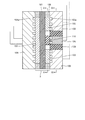
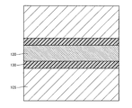
- FIG. 9 is a schematic cross-sectional view showing an example of an alkaline fuel cell that can be provided in the fuel cell unit 10a in the present embodiment, and FIGS. 10 and 11 are respectively an XX line and an XI-XI line shown in FIG. It is a schematic sectional drawing in a line.
- the alkaline fuel cell shown in FIG. 9 includes a membrane electrode assembly (MEA) 3.
- MEA membrane electrode assembly
- the membrane electrode assembly 3 includes an anion conductive electrolyte membrane 101; a first electrode (anode electrode) 103 laminated on the first surface of the anion conductive electrolyte membrane 101; and a first surface of the anion conductive electrolyte membrane 101.
- a second electrode (cathode electrode) 102 stacked on the second surface and a third electrode 110 for self-purge stacked on the first surface spaced apart from the first electrode 103 are mainly configured.
- a gasket 106 (for example, a layer made of an elastic resin such as silicone rubber or a cured resin layer of a curable resin such as an epoxy resin) is provided at the periphery of the electrode to prevent intrusion of air or the like from the electrode end face. Is provided.
- the first electrode 103 and the second electrode 102 are provided to face each other with the anion conductive electrolyte membrane 101 interposed therebetween. Such an opposing arrangement makes the distance between the first electrode 103 and the second electrode 102 the shortest, thereby reducing the resistance when a current flows between these electrodes, thus reducing the power generation efficiency. It is advantageous for suppression.
- the first electrode 103 is divided into two and laminated, and the third electrode 110 is separated from the first electrode 103 between the two first electrodes 103. Is arranged.
- the alkaline fuel cell shown in FIG. 9 includes a first current collecting layer 105 laminated on the first electrode 103; a second current collecting layer 104 laminated on the second electrode 102; and a third electrode.
- the third current collecting layer 120 is stacked on the 110. These current collecting layers are members for exchanging electrons with an electrode in contact with the current collecting layer and for performing electrical wiring.
- the first current collecting layer 105 and the third current collecting layer 120 are electrically insulated from each other by interposing an insulating layer 130 between these current collecting layers.
- the first current collecting layer 105 and the third current collecting layer 120 are provided with a first flow path 105 a for supplying a reducing agent to the first electrode 103 or the third electrode 110.
- each current collecting layer is also a member for supplying a reducing agent and an oxidizing agent.
- the constituent materials of the anion conductive electrolyte membrane 101, the first electrode 103, and the second electrode 102 of the alkaline fuel cell used in the present embodiment are the same as those of the alkaline fuel cell used in the first embodiment. be able to.
- the first electrode 103 and the second electrode 102 are preferably formed to have as large an area as possible on the anion conductive electrolyte membrane 101 from the viewpoint of improving the output per unit area of the fuel cell.
- the anion conductive electrolyte membrane 101 is preferably formed to have the same length or the same length.
- the third electrode 110 is an electrode for Serufupaji, an oxidizing agent supply to the supply and the second electrode 102 of the reducing agent to the third electrode 110 is an electrode for discharging CO 2 from anionic as CO 2 gas.
- the contents described above for the first electrode 103 in the first embodiment are cited.
- the third electrode 110 is disposed on the first surface of the anion conductive electrolyte membrane 101 so as to be separated from the first electrode 103 in order to function independently for self-purging.
- the first electrode 103 is divided into two parts, and the third electrode 110 is formed between them in the central region of the first surface of the anion conductive electrolyte membrane 101.
- the present invention is not limited to such an arrangement.
- the number of the first electrodes 103 (the presence or absence of division) and the positions of the third electrodes 110 are such that the third electrode 110 is arranged on the side of the first electrode 103 without dividing the first electrode 103.
- the ratio between the area (width ⁇ length) of the first electrode 103 and the area of the third electrode 110 is determined in consideration of both the power generation capability of the fuel cell and the self-purge efficiency. If the ratio (the area of the first electrode 103 / the area of the third electrode 110) is too large, the third electrode 110 is too small and the self-purging efficiency is lowered. On the other hand, if the ratio is too small, the first electrode 103 serving as the anode electrode that contributes to power generation is too small to obtain a sufficient output.
- the length of the third electrode 110 is preferably long so that CO 2 -derived anions can be taken from as wide a range as possible of the anion conductive electrolyte membrane 101. For example, the anion conductive electrolyte membrane 101 Or substantially the same length (see FIG. 10).
- the thickness of the first electrode 103 and the thickness of the third electrode 110 are preferably the same.
- the first current collecting layer 105, the second current collecting layer 104, and the third current collecting layer 120 are provided on and in contact with the first electrode 103, the second electrode 102, and the third electrode 110, respectively. It is a member for transferring electrons and performing electrical wiring. In the alkaline fuel cell shown in FIG. 9, these current collecting layers also have a function of supplying a reducing agent and an oxidizing agent.
- the first current collecting layer 105 and the third current collecting layer 120 include: A first flow path 105 a for supplying a reducing agent to the first electrode 103 and the third electrode 110 is provided in the second current collecting layer 104, and a second flow path 104 a for supplying an oxidant to the second electrode 102. Is provided.
- the first current collecting layer 105 and the third current collecting layer 120 are electrically insulated from each other by interposing the insulating layer 130 between these current collecting layers.
- the insulating layer 130 is not particularly limited as long as it exhibits electrical insulation, and can be made of, for example, various nonconductive polymers (including insulating adhesives).
- the material of the current collecting layer is not particularly limited, and for example, a conductive material such as a carbon material, a conductive polymer, various metals, and an alloy typified by stainless steel can be used.
- the material of each current collecting layer may be the same or different.
- the first flow path 105a and the second flow path 104a can be composed of one or more grooves provided on the electrode-side surface of the current collecting layer, and the shape thereof is not particularly limited, and is linear or serpentine Etc.
- the flow path for supplying the reducing agent to the first electrode 103 and the flow path for supplying the reducing agent to the third electrode 110 may or may not be connected.
- a separate member (channel plate) for supplying the reducing agent and the oxidizing agent may be laminated on the current collecting layer.
- the flow path plate may be one in which one or more grooves are provided on the surface of a plate-like body made of a non-conductive material such as various plastic materials.
- FIG. 12 is a schematic cross-sectional view showing another example of an alkaline fuel cell that can be provided in the fuel cell unit 10a in the present embodiment, and FIGS. 13 and 14 are XIII-XIII line and XIV shown in FIG. 12, respectively. It is a schematic sectional drawing in the -XIV line.
- the alkaline fuel cell shown in FIG. 12 is characterized by including a membrane electrode assembly 4 having a plurality of self-purge third electrodes 110 (three in the example of FIG. 12) (see FIGS. 12 and 13).
- the other configuration can be the same as that of the alkaline fuel cell shown in FIG. 9 (possible modifications are the same as those of the alkaline fuel cell shown in FIG. 9).
- the membrane electrode assembly 4 includes an anion conductive electrolyte membrane 101; a first electrode 103 laminated on the first surface of the anion conductive electrolyte membrane 101; a second electrode laminated on the second surface of the anion conductive electrolyte membrane 101. 102; and three third electrodes 110 that are separated from the first electrode 103 and stacked on the first surface.
- the first electrode 103 and the second electrode 102 are provided so as to face each other with the anion conductive electrolyte membrane 101 interposed therebetween.
- the first electrode 103 is divided into two layers and laminated, and the total between the two first electrodes 103 and the outer sides of the two first electrodes 103 are separated from the first electrode 103 in total.
- Three third electrodes 110 are arranged.
- the alkaline fuel cell shown in FIG. 12 includes a first current collecting layer 105 (two in total) laminated on the first electrode 103; a second current collecting layer 104 laminated on the second electrode 102; A third current collecting layer 120 (three in total) is provided on the third electrode 110.
- the first current collecting layer 105 and the third current collecting layer 120 are electrically insulated from each other by interposing an insulating layer 130 between these current collecting layers.
- the first current collecting layer 105 and the third current collecting layer 120 are provided with a first flow path 105a for supplying a reducing agent to the first electrode 103 or the third electrode 110, and the second current collecting layer 105a.
- the layer 104 is provided with a second flow path 104 a for supplying an oxidant to the second electrode 102.
- the plurality of third electrodes 110 are connected to the anion conductive electrolyte membrane 101. It is preferable to disperse and arrange substantially uniformly in the first surface. This is due to the following reason. Since the anion conductive electrolyte membrane 101 is very thin, the ion conduction resistance in the film thickness direction is very small compared to the ion conduction resistance in the in-plane direction.
- the self-purge when the self-purge is advanced, the movement of the CO 2 -derived anion occurs mainly between the anion conductive electrolyte membrane 101 in the vicinity of the third electrode 110 and the second electrode 102 and the third electrode 110, and the self-purge is preferential. Proceed to. On the other hand, since the ion conduction resistance is large between the anion conductive electrolyte membrane 101 and the second electrode 102 and the third electrode 110 in a region far from the third electrode 110, the movement of the CO 2 -derived anion hardly occurs, There is a tendency that self-purge does not progress sufficiently.
- the area in the vicinity of the third electrode 110 can be increased, whereby an anion conducting electrolyte membrane is obtained.
- the self-purge of the entire 101 and the second electrode 102 can be performed.
- the plurality of third electrodes 110 are preferably provided at positions facing the second electrodes 102.
- FIG. 15 is a schematic diagram illustrating a control device according to the present embodiment and an alkaline fuel cell system to which the control device is applied.
- the control device and the alkali are connected to an electronic device (electronic device 50) to which power is supplied.
- 1 shows the configuration of a fuel cell system.
- the control device and alkaline fuel cell system of this embodiment are the same as those of the third embodiment except that the current value changing unit 30 further includes a power supply device 30c in addition to the electronic load device 30a.
- the power supply device 30c is connected in series to the alkaline fuel cell of the fuel cell unit 10a via the switch 30b.
- the switch 30b plays a role of switching between the presence / absence of the power supply device 30c in the circuit connecting the electronic load device 30a and the fuel cell unit 10a.
- an alkaline fuel cell including the third electrode 110 for self-purge is used.
- a power supply device is used. Specifically, the control unit 40a operates the switch 30b to connect the power supply device 30c and the fuel cell unit 10a in series. Further, in some cases, the electromotive force of the power supply device 30c is increased and the electronic load device 30a flows. By increasing the load current, a current of a predetermined current value A or more is allowed to flow between the third electrode and the second electrode for a certain time T 2 such that T 2 / T 0 ⁇ W T.
- the time ratio T 1 / T 0 is constantly detected so that a cycle of unit time T 0 including a certain time during which a current of a predetermined current value A or more flows is repeated.
- the effects [i] to [vi] described above can also be achieved by the control device and alkaline fuel cell system of the present embodiment.
- FIG. 16 is a schematic diagram showing a control device according to the present embodiment and an alkaline fuel cell system to which the control device is applied.
- the control device and the alkali are connected to an electronic device (electronic device 50) to which power is supplied.
- 1 shows the configuration of a fuel cell system.
- the control device and alkaline fuel cell system of the present embodiment include the third electrode on the first electrode side and the fourth electrode on the second electrode side. It is the same as that of the said 1st Embodiment except using the alkaline fuel cell which has a membrane electrode composite further provided with an electrode for the fuel cell part 10a.
- These third electrode and fourth electrode are self-purge electrodes provided independently of the first electrode and the second electrode.
- the third electrode is laminated on the surface of the anion conductive electrolyte membrane on the same side as the first electrode that functions as the anode electrode during power generation, but is disposed apart from (not in contact with) the first electrode.
- the fourth electrode is laminated on the surface of the anion conductive electrolyte membrane on the same side as the second electrode functioning as a cathode electrode during power generation, but is disposed apart from (not in contact with) the second electrode.
- the unit time T in 0, the membrane electrode assembly - the ratio T 1 / T 0 (the first electrode and the second inter-electrode) to the time flows over the current predetermined current value A T 1 is predetermined
- the control unit 40a determines whether the time ratio is less than the time ratio W T , the control unit 40a determines whether the fuel cell unit 10a is generating power (supplying electric power to the electronic device 50) or not.
- the electronic load device 30a is controlled so that a current of a predetermined current value A or more flows between the third electrode and the fourth electrode for a predetermined time.
- a reducing agent is supplied to the third electrode and an oxidizing agent is supplied to the fourth electrode. while (or oxidizing agent to the third electrode, while supplying reducing agent to the fourth electrode), by increasing the load current flowing through the electronic load 30a by the control unit 40a, the T 2 / T 0 ⁇ W T During such a certain time T 2 , a current of a predetermined current value A or more is passed between the third electrode and the fourth electrode.
- the time ratio T 1 / T 0 is constantly detected so that a cycle of unit time T 0 including a certain time during which a current of a predetermined current value A or more flows is repeated.
- the value of the current that flows for a certain time (T 2 ) here is the value obtained by dividing the amount of current flowing between the third electrode and the fourth electrode by the projected area of the cathode electrode (second electrode) onto the electrolyte membrane.
- T 2 the value obtained by dividing the amount of current flowing between the third electrode and the fourth electrode by the projected area of the cathode electrode (second electrode) onto the electrolyte membrane.
- the present embodiment is different from the first embodiment in that a current of a predetermined current value A or more flows between the third electrode (for self-purging) and the fourth electrode (for self-purging) for a certain period of time. Is different. Further, the third embodiment is different from the third embodiment in which a current of a predetermined current value A or more flows between the third electrode (for self-purging) and the second electrode (cathode electrode) for a predetermined time.
- the alkaline fuel cell system of the present embodiment using the alkaline fuel cell having the third electrode and the fourth electrode has the following operational effects [vii].
- Can play That is, if a current of a predetermined current value A or more is allowed to flow between the third electrode and the fourth electrode, the amount of current flowing between the first electrode and the second electrode does not change, and between the first electrode and the second electrode. Therefore, the CO 2 -derived anion concentration can be reduced without reducing the power generation efficiency.
- the electronic load device 30a is connected to the third electrode and the fourth electrode so that a current of a predetermined current value A or more can flow between the third electrode and the fourth electrode of the membrane electrode assembly for a predetermined time.
- the first electrode and the second electrode that contribute to substantial power generation are connected to the electronic device 50 using a wiring different from the wiring that connects the third electrode and the fourth electrode to the electronic load device 30a (see FIG. 16).
- An ammeter for confirming whether or not a current greater than or equal to a predetermined current value A flows may be disposed between the membrane electrode assembly and the electronic load device 30a.
- FIG. 17 is a schematic cross-sectional view showing an example of an alkaline fuel cell that can be provided in the fuel cell unit 10a in the present embodiment.
- FIGS. 18 to 21 are XVIII-XVIII line and XIX-XIX shown in FIG.
- FIG. 4 is a schematic cross-sectional view taken along line XX-XX, XXI-XXI.
- the alkaline fuel cell shown in FIG. 17 includes a membrane electrode assembly (MEA) 5 having a fourth electrode 115 for self-purging in addition to the third electrode 110 for self-purging.
- MEA membrane electrode assembly
- the membrane electrode assembly 5 is laminated on the second surface of the anion conductive electrolyte membrane 101; the first electrode (anode electrode) 103 laminated on the first surface of the anion conductive electrolyte membrane 101; A second electrode (cathode electrode) 102; a third electrode 110 stacked on the first surface spaced apart from the first electrode 103; and a fourth electrode stacked on the second surface spaced apart from the second electrode 102.
- 115 is mainly composed.
- a gasket 106 is provided on the periphery of the electrode.
- the first electrode 103 and the second electrode 102 are provided so as to face each other with the anion conductive electrolyte membrane 101 interposed therebetween.
- the alkaline fuel cell shown in FIG. 17 includes a first current collecting layer 105 laminated on the first electrode 103; a second current collecting layer 104 laminated on the second electrode 102; A third current collecting layer 120; and a fourth current collecting layer 125 laminated on the fourth electrode 115.
- the first current collecting layer 105 and the third current collecting layer 120 are electrically insulated from each other by interposing an insulating layer 130 between these current collecting layers.
- the second current collecting layer 104 and the fourth current collecting layer 125 are electrically insulated from each other with the insulating layer 130 interposed therebetween.
- the first current collecting layer 105 and the third current collecting layer 120 are provided with a first flow path 105 a for supplying a reducing agent to the first electrode 103 or the third electrode 110.
- the second current collecting layer 104 and the fourth current collecting layer 125 are provided with a second flow path 104 a for supplying an oxidant to the second electrode 102 or the fourth electrode 115.
- each current collecting layer is also a member for supplying a reducing agent and an oxidizing agent.
- the constituent materials of the anion conductive electrolyte membrane 101, the first electrode 103, and the second electrode 102 of the alkaline fuel cell used in the present embodiment are the same as those of the alkaline fuel cell used in the first embodiment. be able to.
- the third electrode 110 and the fourth electrode 115 are self-purge electrodes, and by supplying the reducing agent to the third electrode 110 and the oxidizing agent to the fourth electrode 115, the CO 2 -derived anion is generated from the third electrode 110. It is discharged as CO 2 gas (when a reducing agent is supplied to the fourth electrode 115 and an oxidizing agent is supplied to the third electrode, CO 2 -derived anions are discharged from the fourth electrode 115 as CO 2 gas) .
- the configuration and composition of the third electrode 110 and the fourth electrode 115 the contents described above for the first electrode 103 are cited.
- the third electrode 110 is disposed on the first surface of the anion conductive electrolyte membrane 101 so as to be separated from the first electrode 103 in order to function independently for self-purging.
- the fourth electrode 115 is disposed on the second surface of the anion conductive electrolyte membrane 101 so as to be separated from the second electrode 102 in order to function independently for self-purging.
- the third electrode 110 and the fourth electrode 115 are not provided so as to face each other with the anion conductive electrolyte membrane 101 interposed therebetween, but are arranged on one outer side of the first electrode 103.
- the fourth electrode 115 is preferably disposed on the outer side of the second electrode 102 opposite to the side facing the third electrode 110 with respect to the third electrode 110.
- the anion conductive electrolyte membrane 101 passes through a considerably wide area of the anion conductive electrolyte membrane 101 (when the third electrode 110 and the fourth electrode 115 are disposed at almost the end of the membrane electrode assembly). Self-purging can be performed for most regions of the anion conductive electrolyte membrane 101).
- the arrangement configuration of the third electrode 110 and the fourth electrode 115 and the shape of these electrodes are not limited to those shown in the figure, and the shortest path from the third electrode 110 to the fourth electrode 115 is the same as that of the first electrode 103.
- FIG. 22 is a schematic diagram showing a control device according to the present embodiment and an alkaline fuel cell system to which the control device is applied.
- the control device and the alkali are connected to an electronic device (electronic device 50) to which power is supplied.
- 1 shows the configuration of a fuel cell system.
- the control device and the alkaline fuel cell system of this embodiment are the same as those of the fifth embodiment except that the current value changing unit 30 further includes a power supply device 30c in addition to the electronic load device 30a.
- the power supply device 30c is connected in series to the alkaline fuel cell of the fuel cell unit 10a via the switch 30b.
- the switch 30b plays a role of switching between the presence / absence of the power supply device 30c in the circuit connecting the electronic load device 30a and the fuel cell unit 10a.
- an alkaline fuel cell including the third electrode 110 and the fourth electrode 115 for self-purging is used.
- the driving force for forcing a current of a predetermined current value A or more to flow through the membrane electrode assembly is not used.
- a power supply device is used.
- the control unit 40a operates the switch 30b to connect the power supply device 30c and the fuel cell unit 10a in series. Further, in some cases, the electromotive force of the power supply device 30c is increased and the electronic load device 30a flows. By increasing the load current, a current of a predetermined current value A or more is allowed to flow between the third electrode and the fourth electrode for a certain time T 2 such that T 2 / T 0 ⁇ W T.
- the time ratio T 1 / T 0 is constantly detected so that a cycle of unit time T 0 including a certain time during which a current of a predetermined current value A or more flows is repeated.
- the effects [i] to [vii] described above can also be achieved by the control device and alkaline fuel cell system of the present embodiment.
- the detection unit 20 is in the state of “alkaline fuel cell” [a] The ratio T 1 / T of the time T 1 during which a current greater than or equal to the predetermined current value A flows in the membrane electrode assembly within a unit time T 0 .
- the detection unit 20 detects any of the above-mentioned [b] to [e] as “the state of the alkaline fuel cell” Even in such a case, the same effect can be obtained.
- the concentration is detected by the detection unit 20. If it is detected constantly or at regular intervals and it is determined that the concentration exceeds a predetermined concentration, the control unit 40 applies a predetermined value to the membrane electrode assembly regardless of whether the fuel cell unit 10 is generating power.
- the current value changing unit 30 is controlled so that a current greater than or equal to the current value A flows for a certain time.
- the resistance value is constantly or constant by the detection unit 20 by a method such as current interrupt measurement or impedance measurement. If it is detected every hour and it is determined that the resistance value exceeds a predetermined resistance value, the control unit 40 determines whether the fuel cell unit 10 is generating power or not with a predetermined current in the membrane electrode assembly. The current value changing unit 30 is controlled so that a current equal to or greater than the value A flows for a certain time.
- the voltage value of the alkaline fuel cell is detected as “the state of the alkaline fuel cell”
- the voltage value is detected by the detection unit 20 (voltmeter connected to the MEA) at regular time intervals or at regular intervals. If it is determined that the obtained voltage / current characteristic is lower than the predetermined voltage / current characteristic (inferior to the predetermined voltage / current characteristic), the control unit 40 causes the fuel cell unit 10 to generate power. Regardless of whether or not it is performed, the current value changing unit 30 is controlled so that a current of a predetermined current value A or more flows through the membrane electrode assembly for a predetermined time.
- Example 1 A control device and an alkaline fuel cell system having the same configuration as in FIG.
- the catalyst-supported carbon particles (“TEC10E50E” manufactured by Tanaka Kikinzoku Co., Ltd.) having a Pt-supported amount of Pt / C of 50% by weight and the above-obtained electrolyte solution have a weight ratio of 2 / 0.2.
- a catalyst paste for the anode catalyst layer was prepared by mixing and further adding ion exchange water and ethanol.
- a catalyst-supporting carbon particle (“TEC10E50E” manufactured by Tanaka Kikinzoku Co., Ltd.) having a Pt support amount of 50% by weight and Pt / C and the electrolyte solution obtained above are 2 / 0.2 in weight ratio.
- the catalyst paste for the cathode catalyst layer was prepared by mixing the mixture as described above and further adding ion exchange water and ethanol.
- carbon paper (“TGP-H-060” manufactured by Toray Industries Inc., thickness of about 190 ⁇ m) is cut into a size of 23 mm in length and 23 mm in width as an anode gas diffusion layer.
- a catalyst paste for the anode catalyst layer was applied using a screen printing plate having a window of 23 mm in length and 23 mm in width so that the amount of catalyst was 0.5 mg / cm 2, and dried at room temperature.
- carbon paper (“TGP-H-060” manufactured by Toray Industries Inc., thickness of about 190 ⁇ m) is cut into a size of 23 mm in length ⁇ 23 mm in width as a cathode gas diffusion layer
- the cathode paste for the cathode catalyst layer was applied using a screen printing plate having a window of 23 mm in length and 23 mm in width so that the amount of catalyst was 0.5 mg / cm 2, and dried at room temperature.
- a cathode electrode (second electrode) in which a cathode catalyst layer was formed on the entire surface of one side of carbon paper as a gas diffusion layer was produced.
- the thickness of the obtained cathode electrode was about 200 ⁇ m.
- a fluororesin polymer electrolyte (“Aciplex” manufactured by Asahi Kasei Co., Ltd.) cut into a size of 50 mm ⁇ 50 mm is used as the anion conductive solid polymer electrolyte membrane, and the anode electrode, the electrolyte membrane, and the cathode electrode are used as the anion conductive solid polymer electrolyte membrane.
- the anode electrode and the cathode electrode are joined to the electrolyte membrane by thermocompression bonding at 130 ° C. and 10 kN for 2 minutes, and the membrane electrode composite Got the body.
- the superposition was performed so that the positions of the anode electrode and the cathode electrode in the plane of the electrolyte membrane coincided and the centers of the anode electrode, the electrolyte membrane, and the cathode electrode coincided.
- a fuel cell was produced by combining the membrane electrode assembly with a part obtained by disassembling a commercially available fuel cell (manufactured by Electrochem). Specifically, first, anode electrode side current collector (end plate) / carbon anode electrode separator (having a reducing agent supply channel (first channel)) / polytetrafluoroethylene gasket / Laminate in the order of membrane electrode composite / polytetrafluoroethylene gasket / carbon cathode electrode separator (equipped with an oxidizing agent supply channel (second channel)) / cathode electrode side current collector (end plate) did.
- anode electrode side current collector (end plate) / carbon anode electrode separator having a reducing agent supply channel (first channel)
- polytetrafluoroethylene gasket / Laminate in the order of membrane electrode composite / polytetrafluoroethylene gasket / carbon cathode electrode separator (equipped with an oxidizing agent supply channel (second channel)) / cathode electrode
- control device having the same configuration as that shown in FIG. 4 is manufactured, and the alkaline fuel cell manufactured as described above is used as the fuel cell unit 10a. Produced. Specifically, it is as follows.
- the reducing agent supply pipe is connected so that the reducing agent can be supplied to the anode separator of the fuel cell unit 10a, and the oxidant supply pipe is connected so that the oxidizing agent can be supplied to the cathode electrode separator of the fuel cell unit 10a.
- a charge / discharge battery system (“PFX2011” manufactured by Kikusui Electric Co., Ltd., an ammeter, a voltmeter, and an electronic load device are integrally provided) as the detection unit 20a and the electronic load device 30a is provided as an anode of the fuel cell unit 10a.
- the electrode side current collector and the cathode side electrode current collector were connected.
- the detection unit 20a detects a ratio T 1 / T 0 of time T 1 during which a current of a predetermined current value A or more flows between the first electrode and the second electrode of the membrane electrode assembly within the unit time T 0 .
- the control unit 40a includes a personal computer [time measuring means (timer) and storage means (memory) for storing current values and times T 0 and T 1 . Is connected to the charge / discharge battery system so that the detection result can be received, and control information can be transmitted to the charge / discharge battery system based on the detection result.
- Example 1 [Evaluation of power generation efficiency of alkaline fuel cells] (1)
- the control device (alkaline fuel cell system) of Example 1 in which the time T 2 is set to 1 minute, the operation of the fuel cell unit 10a (alkaline fuel cell) is stopped (current value 0 mA / cm 2 ).
- the control device (alkaline fuel cell system) of the first embodiment by operating the fuel cell unit 10a (alkaline fuel cell) at a current value of 100 mA / cm 2 , a current value of 100 mA / cm 2 (9 minutes) ) ⁇ current value 600 mA / cm 2 (1 minute) ⁇ current value 100 mA / cm 2 (9 minutes) ⁇ ...
- a current of 600 mA / cm 2 was forcibly passed through the membrane electrode assembly in a pattern of .
- the alkaline fuel cell system of Comparative Example 1 was operated at a current value of 100 mA / cm 2 for 2 hours without performing an operation of forcibly passing a current through the membrane electrode assembly, and then 200 mA / cm.
- the current of 2 was taken out, the power generation efficiency after 5 minutes was 35%, and it took 15 minutes to obtain the power generation efficiency of 50%.
- Membrane electrode assembly 10 10a Fuel cell unit, 20, 20a detection unit, 30 Current value change unit, 30a Electronic load device, 30b switch, 30c Power supply device, 40, 40a control unit 50, electronic equipment, 101, anion conductive electrolyte membrane, 102, second electrode, 103, first electrode, 104, second current collecting layer, 104a, second flow path, 105, first current collecting layer, 105a, first flow path, 106 gasket , 110 third electrode, 115 fourth electrode, 120 third current collecting layer, 125 fourth current collecting layer, 130 insulating layer.
Landscapes
- Life Sciences & Earth Sciences (AREA)
- Engineering & Computer Science (AREA)
- Manufacturing & Machinery (AREA)
- Sustainable Development (AREA)
- Sustainable Energy (AREA)
- Chemical & Material Sciences (AREA)
- Chemical Kinetics & Catalysis (AREA)
- Electrochemistry (AREA)
- General Chemical & Material Sciences (AREA)
- Fuel Cell (AREA)
Applications Claiming Priority (2)
| Application Number | Priority Date | Filing Date | Title |
|---|---|---|---|
| JP2011-062618 | 2011-03-22 | ||
| JP2011062618A JP5650025B2 (ja) | 2011-03-22 | 2011-03-22 | 制御装置および燃料電池システム |
Publications (1)
| Publication Number | Publication Date |
|---|---|
| WO2012127999A1 true WO2012127999A1 (ja) | 2012-09-27 |
Family
ID=46879158
Family Applications (1)
| Application Number | Title | Priority Date | Filing Date |
|---|---|---|---|
| PCT/JP2012/054939 Ceased WO2012127999A1 (ja) | 2011-03-22 | 2012-02-28 | 制御装置および燃料電池システム |
Country Status (2)
| Country | Link |
|---|---|
| JP (1) | JP5650025B2 (https=) |
| WO (1) | WO2012127999A1 (https=) |
Families Citing this family (1)
| Publication number | Priority date | Publication date | Assignee | Title |
|---|---|---|---|---|
| JP6075924B2 (ja) * | 2013-09-13 | 2017-02-08 | 株式会社日本自動車部品総合研究所 | 燃料電池単セルおよびその製造方法 |
Citations (9)
| Publication number | Priority date | Publication date | Assignee | Title |
|---|---|---|---|---|
| JP2006040868A (ja) * | 2004-06-21 | 2006-02-09 | Hitachi Cable Ltd | 燃料電池の特性復帰方法および特性復帰装置 |
| JP2008192468A (ja) * | 2007-02-05 | 2008-08-21 | Toyota Motor Corp | 燃料電池システム |
| JP2008218051A (ja) * | 2007-02-28 | 2008-09-18 | Nissan Motor Co Ltd | 燃料電池の制御方法 |
| WO2008117485A1 (ja) * | 2007-03-27 | 2008-10-02 | Daihatsu Motor Co., Ltd. | 燃料電池 |
| JP2009004286A (ja) * | 2007-06-25 | 2009-01-08 | Hitachi Zosen Corp | アルカリ型燃料電池用アノード膜電極接合体およびそれをアノードとして用いたアルカリ型燃料電池 |
| WO2009093651A1 (ja) * | 2008-01-23 | 2009-07-30 | Nec Corporation | 燃料電池及びその制御方法 |
| JP2009245859A (ja) * | 2008-03-31 | 2009-10-22 | Toshiba Corp | 燃料電池装置およびその駆動方法 |
| JP2010182589A (ja) * | 2009-02-06 | 2010-08-19 | Toyota Motor Corp | 燃料電池システム |
| JP2011216418A (ja) * | 2010-04-01 | 2011-10-27 | Toyota Motor Corp | 燃料電池システム |
-
2011
- 2011-03-22 JP JP2011062618A patent/JP5650025B2/ja not_active Expired - Fee Related
-
2012
- 2012-02-28 WO PCT/JP2012/054939 patent/WO2012127999A1/ja not_active Ceased
Patent Citations (9)
| Publication number | Priority date | Publication date | Assignee | Title |
|---|---|---|---|---|
| JP2006040868A (ja) * | 2004-06-21 | 2006-02-09 | Hitachi Cable Ltd | 燃料電池の特性復帰方法および特性復帰装置 |
| JP2008192468A (ja) * | 2007-02-05 | 2008-08-21 | Toyota Motor Corp | 燃料電池システム |
| JP2008218051A (ja) * | 2007-02-28 | 2008-09-18 | Nissan Motor Co Ltd | 燃料電池の制御方法 |
| WO2008117485A1 (ja) * | 2007-03-27 | 2008-10-02 | Daihatsu Motor Co., Ltd. | 燃料電池 |
| JP2009004286A (ja) * | 2007-06-25 | 2009-01-08 | Hitachi Zosen Corp | アルカリ型燃料電池用アノード膜電極接合体およびそれをアノードとして用いたアルカリ型燃料電池 |
| WO2009093651A1 (ja) * | 2008-01-23 | 2009-07-30 | Nec Corporation | 燃料電池及びその制御方法 |
| JP2009245859A (ja) * | 2008-03-31 | 2009-10-22 | Toshiba Corp | 燃料電池装置およびその駆動方法 |
| JP2010182589A (ja) * | 2009-02-06 | 2010-08-19 | Toyota Motor Corp | 燃料電池システム |
| JP2011216418A (ja) * | 2010-04-01 | 2011-10-27 | Toyota Motor Corp | 燃料電池システム |
Also Published As
| Publication number | Publication date |
|---|---|
| JP2012199082A (ja) | 2012-10-18 |
| JP5650025B2 (ja) | 2015-01-07 |
Similar Documents
| Publication | Publication Date | Title |
|---|---|---|
| Kamarudin et al. | Overview on the application of direct methanol fuel cell (DMFC) for portable electronic devices | |
| Li et al. | A high-performance integrated electrode for anion-exchange membrane direct ethanol fuel cells | |
| JP2006040598A (ja) | 燃料電池の活性化方法 | |
| JP6998797B2 (ja) | 有機ハイドライド製造装置、有機ハイドライドの製造方法およびエネルギー輸送方法 | |
| JP5198044B2 (ja) | 直接酸化型燃料電池 | |
| JP4428774B2 (ja) | 燃料電池電極の製造方法 | |
| WO2013027501A1 (ja) | 制御装置および燃料電池システム | |
| Pasupathi et al. | Recent advances in high-temperature PEM fuel cells | |
| JP5650025B2 (ja) | 制御装置および燃料電池システム | |
| JP2018006318A (ja) | 電池用分離板及びこれを含むレドックスフロー電池または燃料電池 | |
| JP2009004282A (ja) | 燃料電池、膜−電極接合体、及び膜−触媒層接合体 | |
| JPWO2013080415A1 (ja) | 燃料電池システム | |
| JP2006134648A (ja) | 固体高分子型燃料電池の電極構造体 | |
| JP5752430B2 (ja) | アルカリ形燃料電池およびその使用方法 | |
| JP2012074205A (ja) | 膜電極複合体およびアルカリ形燃料電池 | |
| JP2006134640A (ja) | 固体高分子型燃料電池及びその製造方法 | |
| JP5657413B2 (ja) | アルカリ形燃料電池システム | |
| JP5731324B2 (ja) | アルカリ形燃料電池 | |
| Atri et al. | A Review of Water Electrolysis, Fuel Cells and Its Use in Energy Storage | |
| JP5742394B2 (ja) | 固体高分子形燃料電池のエージング方法、及び固体高分子形燃料電池の発電システム | |
| JP2012059481A (ja) | 膜電極複合体およびアルカリ形燃料電池 | |
| Kim et al. | Asymmetric Vanadium‐based Aqueous Flow Batteries | |
| JP5748984B2 (ja) | 燃料電池システムおよびその運転方法 | |
| JP5657412B2 (ja) | アルカリ形燃料電池システム | |
| JP2008004402A (ja) | ダイレクトメタノール型燃料電池用アノード電極及びそれを用いたダイレクトメタノール型燃料電池 |
Legal Events
| Date | Code | Title | Description |
|---|---|---|---|
| DPE2 | Request for preliminary examination filed before expiration of 19th month from priority date (pct application filed from 20040101) | ||
| 121 | Ep: the epo has been informed by wipo that ep was designated in this application |
Ref document number: 12761103 Country of ref document: EP Kind code of ref document: A1 |
|
| NENP | Non-entry into the national phase |
Ref country code: DE |
|
| 122 | Ep: pct application non-entry in european phase |
Ref document number: 12761103 Country of ref document: EP Kind code of ref document: A1 |