WO2012127999A1 - Control device and fuel-cell system - Google Patents
Control device and fuel-cell system Download PDFInfo
- Publication number
- WO2012127999A1 WO2012127999A1 PCT/JP2012/054939 JP2012054939W WO2012127999A1 WO 2012127999 A1 WO2012127999 A1 WO 2012127999A1 JP 2012054939 W JP2012054939 W JP 2012054939W WO 2012127999 A1 WO2012127999 A1 WO 2012127999A1
- Authority
- WO
- WIPO (PCT)
- Prior art keywords
- electrode
- fuel cell
- current value
- current
- unit
- Prior art date
Links
Images


Classifications
-
- H—ELECTRICITY
- H01—ELECTRIC ELEMENTS
- H01M—PROCESSES OR MEANS, e.g. BATTERIES, FOR THE DIRECT CONVERSION OF CHEMICAL ENERGY INTO ELECTRICAL ENERGY
- H01M8/00—Fuel cells; Manufacture thereof
- H01M8/04—Auxiliary arrangements, e.g. for control of pressure or for circulation of fluids
- H01M8/04298—Processes for controlling fuel cells or fuel cell systems
- H01M8/04694—Processes for controlling fuel cells or fuel cell systems characterised by variables to be controlled
- H01M8/04858—Electric variables
- H01M8/04895—Current
- H01M8/0491—Current of fuel cell stacks
-
- H—ELECTRICITY
- H01—ELECTRIC ELEMENTS
- H01M—PROCESSES OR MEANS, e.g. BATTERIES, FOR THE DIRECT CONVERSION OF CHEMICAL ENERGY INTO ELECTRICAL ENERGY
- H01M8/00—Fuel cells; Manufacture thereof
- H01M8/04—Auxiliary arrangements, e.g. for control of pressure or for circulation of fluids
- H01M8/04298—Processes for controlling fuel cells or fuel cell systems
- H01M8/04313—Processes for controlling fuel cells or fuel cell systems characterised by the detection or assessment of variables; characterised by the detection or assessment of failure or abnormal function
- H01M8/04537—Electric variables
- H01M8/04574—Current
- H01M8/04589—Current of fuel cell stacks
-
- H—ELECTRICITY
- H01—ELECTRIC ELEMENTS
- H01M—PROCESSES OR MEANS, e.g. BATTERIES, FOR THE DIRECT CONVERSION OF CHEMICAL ENERGY INTO ELECTRICAL ENERGY
- H01M8/00—Fuel cells; Manufacture thereof
- H01M8/08—Fuel cells with aqueous electrolytes
- H01M8/083—Alkaline fuel cells
-
- Y—GENERAL TAGGING OF NEW TECHNOLOGICAL DEVELOPMENTS; GENERAL TAGGING OF CROSS-SECTIONAL TECHNOLOGIES SPANNING OVER SEVERAL SECTIONS OF THE IPC; TECHNICAL SUBJECTS COVERED BY FORMER USPC CROSS-REFERENCE ART COLLECTIONS [XRACs] AND DIGESTS
- Y02—TECHNOLOGIES OR APPLICATIONS FOR MITIGATION OR ADAPTATION AGAINST CLIMATE CHANGE
- Y02E—REDUCTION OF GREENHOUSE GAS [GHG] EMISSIONS, RELATED TO ENERGY GENERATION, TRANSMISSION OR DISTRIBUTION
- Y02E60/00—Enabling technologies; Technologies with a potential or indirect contribution to GHG emissions mitigation
- Y02E60/30—Hydrogen technology
- Y02E60/50—Fuel cells
Definitions
- the present invention relates to a fuel cell control device capable of operating a fuel cell with high power generation efficiency and a fuel cell system using the same.
- the fuel cell includes a membrane electrode assembly (MEA) having a configuration in which an electrolyte membrane is sandwiched between an anode and a cathode as a main part of power generation.
- MEA membrane electrode assembly
- a polymer electrolyte fuel cell (direct fuel) Battery) phosphoric acid fuel cell, molten carbonate fuel cell, solid oxide fuel cell, alkaline fuel cell and the like.
- the alkaline fuel cell is a fuel cell in which an anion conductive electrolyte membrane (anion exchange membrane) is used as an electrolyte membrane, and charge carriers are hydroxide ions (OH ⁇ ).
- anion exchange membrane anion exchange membrane
- charge carriers are hydroxide ions (OH ⁇ ).
- the supplied reducing agent (fuel), for example, H 2 gas and OH ⁇ transmitted from the cathode electrode are expressed by the following formula (2):
- Alkaline fuel cells have advantages such as fewer restrictions on constituent materials such as catalysts and can be manufactured at a lower cost, but unlike other fuel cells, the electrolyte of the electrolyte membrane and catalyst layer is an anion conductive electrolyte. Therefore, the electrolyte membrane and the catalyst layer absorb carbon dioxide (CO 2 ) in the environment, and OH ⁇ in the electrolyte membrane and the catalyst layer is represented by the following formulas (3) and (4): CO 2 + 2OH ⁇ ⁇ CO 3 2 ⁇ + H 2 O (3) CO 2 + OH - ⁇ HCO 3 - (4) It has an inherent problem that it is easily replaced by CO 3 2 ⁇ and / or HCO 3 ⁇ (hereinafter sometimes referred to as “CO 2 -derived anion”) by such a reaction.
- CO 2 + 2OH ⁇ ⁇ CO 3 2 ⁇ + H 2 O CO 2 + OH - ⁇ HCO 3 - (4)
- Non-Patent Document 1 It is known that the problem of increase in cell resistance can be improved by a phenomenon called “self-purge” caused by operation of an alkaline fuel cell [for example, Hiroyuki Yanagi, and Kenji Fukuta, ECS Transactions, 16 (2), 257- 262 (2008) (Non-Patent Document 1)].
- “Self-purge” refers to the cause of a decrease in anion conductivity due to the operation of an alkaline fuel cell.
- the CO 2 -derived anion contained in the electrolyte membrane and the catalyst layer moves to the anode electrode and is reduced by the reducing agent. This refers to the phenomenon of being discharged from the anode electrode as two gases.
- the following formulas (5) and (6): H 2 + CO 3 2 ⁇ ⁇ CO 2 + H 2 O + 2e ⁇ (5) H 2 + 2HCO 3 ⁇ ⁇ 2CO 2 + 2H 2 O + 2e ⁇ (6) Can be expressed as
- the power generation amount of the fuel cell is adjusted according to the power consumption of the electronic device using the fuel cell as a power source.
- the power generation amount that is, the operating current value
- the present invention has been made in view of the above problems, and an object of the present invention is to provide a fuel cell control device capable of operating a fuel cell with high power generation efficiency and a fuel cell system using the same.
- the present invention is connected to a detection unit for detecting the state of the fuel cell, a current value changing unit for changing a current value flowing through the membrane electrode assembly of the fuel cell, a detection unit and a current value changing unit.
- a control device is provided that includes a control unit for controlling the current value changing unit so that a current equal to or greater than a predetermined current value A flows through the membrane electrode assembly for a certain period of time according to the detection result of the detection unit.
- the fuel cell is preferably an alkaline fuel cell comprising a membrane electrode assembly having an anion conductive electrolyte membrane as an electrolyte membrane.
- the predetermined current value A is in the range of 600 to 1000 mA / cm 2 , for example.
- the detection unit preferably detects a ratio T 1 / T 0 of time T 1 during which a current equal to or greater than a predetermined current value A flows through the membrane electrode assembly within unit time T 0 .
- the current value changing unit may include at least an electronic load device or a variable resistor connected to the alkaline fuel cell. Further, the current value changing unit may include an electronic load device or a variable resistor connected to the alkaline fuel cell and a power supply device connected in series to the alkaline fuel cell.
- the membrane electrode assembly includes an anion conductive electrolyte membrane, a first electrode laminated on the first surface of the anion conductive electrolyte membrane, and a first surface of the anion conductive electrolyte membrane.
- the detection unit has a time during which a current of a predetermined current value A or more flows between the first electrode and the second electrode within the unit time T 0 . is used to detect the ratio T 1 / T 0 of T 1, the current value changing unit is for changing the current flowing between the first electrode and the second electrode, the control unit, the detection unit According to the detection result, the current value changing unit is controlled so that a current of a predetermined current value A or more flows between the first electrode and the second electrode for a predetermined time.
- the first electrode may be an anode electrode during power generation
- the second electrode may be a cathode electrode during power generation.
- the membrane electrode assembly includes an anion conductive electrolyte membrane, a first electrode laminated on the first surface of the anion conductive electrolyte membrane, and a first surface of the anion conductive electrolyte membrane.
- the second electrode is stacked on the second surface opposite to the first electrode, and the third electrode is stacked on the first surface spaced apart from the first electrode.
- the detection unit includes the first electrode within the unit time T 0 .
- the ratio T 1 / T 0 of the time T 1 during which a current greater than or equal to the predetermined current value A flows between the first electrode and the second electrode is detected.
- the control unit is configured to change a current value that flows between the third electrode and the second electrode according to a detection result of the detection unit so that a current greater than or equal to a predetermined current value A flows for a certain period of time.
- the value changing unit is controlled.
- the first electrode can be an anode electrode during power generation
- the second electrode can be a cathode electrode during power generation.
- the membrane electrode assembly includes an anion conductive electrolyte membrane, a first electrode laminated on a first surface of the anion conductive electrolyte membrane, and a first of the anion conductive electrolyte membrane.
- a second electrode stacked on the second surface facing the surface; a third electrode stacked on the first surface spaced apart from the first electrode; and a second electrode stacked on the second surface spaced apart from the second electrode.
- the detection unit detects the ratio T 1 / T 0 of the time T 1 during which a current of a predetermined current value A or more flows between the first electrode and the second electrode within the unit time T 0 .
- the current value changing unit changes a current value flowing between the third electrode and the fourth electrode, and the control unit changes the third electrode and the second electrode according to the detection result by the detecting unit.
- the current value changing unit is controlled so that a current of a predetermined current value A or more flows between the four electrodes for a predetermined time.
- the first electrode can be an anode electrode during power generation
- the second electrode can be a cathode electrode during power generation.
- the volume of the catalyst layer of the first electrode as the anode electrode is also preferable to make the volume of the catalyst layer of the second electrode larger than the volume of the catalyst layer of the second electrode as the cathode electrode.
- the present invention also provides a fuel cell system comprising a fuel cell unit including the fuel cell and a control device according to the present invention.
- the fuel cell can be operated with high power generation efficiency.
- FIG. 10 is a schematic sectional view taken along line XX shown in FIG. 9.
- FIG. 10 is a schematic cross-sectional view taken along line XI-XI shown in FIG. 9.
- FIG. 13 is a schematic sectional view taken along line XIII-XIII shown in FIG. 12. It is a schematic sectional drawing in the XIV-XIV line
- FIG. 18 is a schematic sectional view taken along line XVIII-XVIII shown in FIG.
- FIG. 18 is a schematic sectional view taken along line XIX-XIX shown in FIG. 17.
- FIG. 18 is a schematic sectional view taken along line XX-XX shown in FIG.
- FIG. 18 is a schematic sectional view taken along line XXI-XXI shown in FIG. 17.
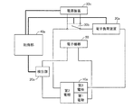
- FIG. 1 is a schematic diagram showing a configuration of a control device according to the present invention and a fuel cell system to which the control device is applied.
- the control device of the present invention is connected to a fuel cell unit 10 (fuel cell) including a fuel cell, and a detection unit 20 for detecting the state of the fuel cell;
- a current value changing unit 30 for changing a current value of a current flowing through the membrane electrode assembly of the fuel cell; and a control unit connected to the detecting unit 20 and the current value changing unit 30 40 is basically provided.
- the control unit 40 receives a detection result (information signal) related to the state of the fuel cell from the detection unit 20, and according to the received detection result, a current of a predetermined current value A or more flows through the membrane electrode assembly for a certain period of time.
- the current value changing unit 30 is controlled.
- the fuel cell system of the present invention includes a fuel cell unit 10 including a fuel cell; a detection unit 20 connected to the fuel cell unit 10 (fuel cell) and detecting the state of the fuel cell; A current value changing unit 30 for changing a current value of a current flowing through the membrane electrode assembly of the fuel cell; and a control unit connected to the detecting unit 20 and the current value changing unit 30 40 is basically provided.
- the fuel cell constituting the fuel cell unit 10 is preferably an alkaline fuel cell including a membrane electrode assembly having an anion conductive electrolyte membrane.
- the control device of the present invention controls the fuel cell so that a current of a predetermined current value A or more flows through the membrane electrode assembly of the fuel cell for a “certain time”.
- FIG. 2 is a conceptual diagram showing a state in which a cycle in which a current of a predetermined current value A or more flows for a certain period of time within a unit time is repeated in the fuel cell membrane electrode assembly.
- a current of a predetermined current value A or more flows through the membrane electrode assembly for a certain period of time means that the fuel cell supplies power to an electronic device using this as a power source.
- a current equal to or greater than the predetermined current value A flows for a certain period of time within the unit time T 0 regardless of whether or not the power is being generated (that is, whether or not power is being generated).
- a cycle of unit time T 0 including a certain time during which a current of a predetermined current value A or more flows is repeated.
- a cycle of unit time T 0 including a certain time during which a current of a predetermined current value A or more is flowing is repeated two or more times, all the above certain times may have the same time length, or two or more kinds Different time lengths may be included.
- the current passed through the membrane electrode assembly is not particularly limited as long as it is equal to or greater than the predetermined current value A, and may all be the same current value or may include two or more different current values.
- a current greater than or equal to the predetermined current value A may be supplied a plurality of times within the unit time T 0 .
- the self-purge is repeated by repeating the cycle of the unit time T 0 including a certain time during which a current of a predetermined current value A or more flows, the CO 2 -derived anion concentration in the membrane electrode complex Can be maintained in a substantially low state, and accumulation of CO 2 -derived anions can be suppressed.
- the problems of an increase in cell resistance and an increase in reaction overvoltage at the anode electrode are improved, and the power generation efficiency of the alkaline fuel cell can be improved.
- FIG. 3 shows only one unit time T 0 including a certain time during which a current of a predetermined current value A or more flows through the membrane electrode assembly of an alkaline fuel cell (a current of a predetermined current value A or more is It shows conceptually how the CO 2 -derived anion concentration changes when it flows only once).
- a current of a predetermined current value A or more flows through the membrane electrode assembly for a certain period of time includes a case where the current of a predetermined current value A or more flows as shown in FIG. Although there may be a case where there is only one unit time T 0 , such a cycle of unit time T 0 is preferably repeated as shown in FIG. This is because the CO 2 -derived anion concentration in the membrane electrode complex can be maintained substantially always low.
- T 0 including a certain time during which a current equal to or greater than the predetermined current value A flows, sufficiently high power generation efficiency is obtained when the fuel cell generates power after the unit time T 0. There is a risk of not being able to.
- a current of a predetermined current value A or more flows. There may be only one unit time T 0 including a certain time.
- control device of the present invention and the fuel cell system (particularly an alkaline fuel cell system) to which the control device is applied can have the following operational effects.
- the CO 2 -derived anion concentration in the membrane electrode assembly can be maintained in a state that is always kept low, so that a fuel cell (alkaline fuel cell) can be generated in a state in which an increase in cell resistance and an increase in reaction overvoltage at the anode electrode are suppressed. Can be improved.
- the surplus power (power exceeding the amount required by the electronic device) is compared with the case where the operating current value is continuously increased. ) Can be suppressed. This also contributes to the improvement of power generation efficiency.
- the surplus power may be stored in, for example, a storage battery (not shown).
- the state of the fuel cell” detected by the detection unit 20 refers to an index (parameter) that can evaluate the CO 2 -derived anion concentration in the membrane electrode assembly.
- Specific examples of the battery include the following.
- [A] is in the unit time T in 0, the ratio T 1 / T 0 of the time predetermined current value A or more current flows through the membrane electrode assembly T 1, [B] CO 2 -derived anion concentration (or CO 3 2 ⁇ concentration of these) in the anion conductive electrolyte membrane, [C] pH of the anion conductive electrolyte membrane, [D] resistance value of the anion conductive electrolyte membrane, [E] Output voltage value of alkaline fuel cell.
- the detection unit 20 detects [a] because it is an index that affects the CO 2 -derived anion concentration in the membrane electrode complex and the detection method is relatively easy. It is preferable.
- control device for controlling an alkaline fuel cell and an alkaline fuel cell system to which the control device is applied, and detects the above [a] as the state of the alkaline fuel cell.
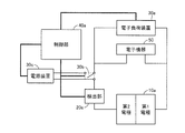
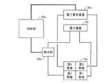
- FIG. 4 is a schematic diagram showing a control device according to the present embodiment and an alkaline fuel cell system to which the control device is applied.
- the control device and the alkali are connected to an electronic device (electronic device 50) to which power is supplied.
- 1 shows the configuration of a fuel cell system.
- the control device according to the present embodiment includes the above-described detection unit 20 connected to a fuel cell unit 10a as a fuel cell unit 10 including an alkaline fuel cell including a membrane electrode assembly having an anion conductive electrolyte membrane.
- Detection unit 20a for detecting (a ratio T 1 / T 0 of time T 1 in which a current equal to or greater than a predetermined current value A flows in the membrane electrode assembly within a certain unit time T 0 ); connected to the fuel cell unit 10a And an electronic load device 30a for changing the current value of the current flowing through the membrane electrode assembly of the alkaline fuel cell as the current value changing unit 30 connected in parallel to the electronic device 50; and
- the electronic load device 30a is connected to the detection unit 20a and the electronic load device 30a, and the electronic load device 30a is controlled so that a current of a predetermined current value A or more flows through the membrane electrode assembly for a predetermined time according to the detection result by the detection unit 20a.
- a control unit 40a is provided.
- the fuel cell unit 10a is illustrated in a form showing only the first electrode (for example, the anode electrode) and the second electrode (for example, the cathode electrode) of the membrane electrode assembly included in the alkaline fuel cell.
- first electrode for example, the anode electrode
- second electrode for example, the cathode electrode
- the alkaline fuel cell of the fuel cell unit can take.
- the detection unit 20a is a fuel cell unit for measuring a current value flowing through the membrane electrode assembly (more specifically, a current value flowing between the first electrode and the second electrode of the membrane electrode assembly). At least an ammeter connected to 10a (alkaline fuel cell) is provided, and together with this ammeter, a unit time T 0 and a time T 1 when a current of a predetermined current value A or more flows through the membrane electrode assembly are measured.
- Time measuring means such as a timer
- storage means such as a memory
- the time measuring means and the storage means can be included in the control unit 40a.
- the controller 40a is not particularly limited as long as it can control the electronic load device 30a so that a current equal to or greater than the predetermined current value A flows through the membrane electrode assembly for a certain period of time according to the detection result by the detector 20a.
- it can be a personal computer.
- the detection unit 20a preferably detects the time ratio T 1 / T 0 at all times, and the control unit 40a determines that the time ratio T 1 / T 0 is less than the predetermined time ratio W T.
- the control unit 40a applies the predetermined current value A to the membrane electrode assembly (between the first electrode and the second electrode) regardless of whether the fuel cell unit 10a is generating power (supplying power to the electronic device 50).
- the electronic load device 30a is controlled so that the above current flows for a certain period of time (for example, a current waveform pattern as shown in FIG. 2 is obtained).
- the control unit 40a determines that the time ratio T 1 / T 0 is less than the predetermined time ratio W T , a reducing agent is supplied to the first electrode and an oxidizing agent is supplied to the second electrode.
- a predetermined time T 2 such that T 2 / T 0 ⁇ W T is established between the first electrode and the second electrode.
- a current greater than A is supplied.
- the time ratio T 1 / T 0 is constantly detected so that a cycle of unit time T 0 including a certain time during which a current of a predetermined current value A or more flows is repeated.
- the fuel cell unit 10a performs power generation (power supply to the electronic device 50) in order to achieve a substantially always low CO 2 -derived anion concentration
- the control unit 40a is forced to exceed the predetermined current value A according to the control flow.
- the CO 2 -derived anion is substantially always low. Concentration is realized.
- the unit time T 0 is not particularly limited, and can be, for example, in the range of about 10 to 30 minutes.
- the predetermined time ratio W T is determined in consideration of a desired degree of improvement in power generation efficiency and a degree of improvement in start-up time, and can be selected from a range of 5 to 20% (for example, 10%), for example.
- the predetermined current value A is also determined in consideration of the desired degree of improvement in power generation efficiency and the degree of start-up time, and is selected from a range of 400 to 1000 mA / cm 2 , preferably 600 to 1000 mA / cm 2. be able to.
- the current value (both the current value detected by the detection unit and the current value of the current that flows for a certain period of time (T 2 )) in the present invention refers to a membrane electrode assembly (first electrode-second electrode in this embodiment).
- the value of “current greater than or equal to the predetermined current value A” that is passed through the membrane electrode assembly for a certain time (time length T 2 ) according to the detection result by the detection unit 20a is detected by the detection unit 20a as “unit time T 0.
- T 2 is normally set to be longer than T 1 .
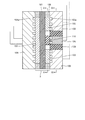
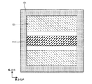
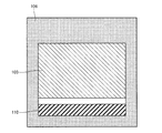
- FIG. 5 is a schematic cross-sectional view showing an example of an alkaline fuel cell that can be provided in the fuel cell unit 10a in the present embodiment.
- the alkaline fuel cell shown in FIG. 5 includes an anion conductive electrolyte membrane 101, a first electrode (anode electrode) 103 laminated on the first surface of the anion conductive electrolyte membrane 101, and a first of the anion conductive electrolyte membrane 101.
- a membrane electrode assembly (MEA) 1 composed of a second electrode (cathode electrode) 102 laminated on a second surface facing the surface is provided.
- the first electrode 103 and the second electrode 102 are provided so as to face each other with the anion conductive electrolyte membrane 101 interposed therebetween.
- a gasket 106 (for example, a layer made of an elastic resin such as silicone rubber or a cured resin layer of a curable resin such as an epoxy resin) is provided at the periphery of the electrode to prevent intrusion of air or the like from the electrode end face. Is provided.
- the alkaline fuel cell shown in FIG. 5 includes a first current collecting layer 105 laminated on the first electrode 103 and a second current collecting layer 104 laminated on the second electrode 102. These current collecting layers are members for exchanging electrons with an electrode in contact with the current collecting layer and for performing electrical wiring.
- the first current collecting layer 105 is provided with a first flow path 105 a for supplying a reducing agent to the first electrode 103.
- the second current collection layer 104 is provided with a second flow path 104 a for supplying an oxidant to the second electrode 102.
- each current collecting layer is also a member for supplying a reducing agent and an oxidizing agent.
- the anion-conducting electrolyte membrane 101 has an electrical insulation property in order to conduct OH - ions and prevent a short circuit between the first electrode 103 and the second electrode 102. Although it does not restrict
- Preferred examples of the anion conductive solid polymer electrolyte membrane include, for example, perfluorosulfonic acid, perfluorocarboxylic acid, styrene vinylbenzene, and quaternary ammonium solid polymer electrolyte membranes (anion exchange membranes). .
- a membrane obtained by impregnating polyacrylic acid with a concentrated potassium hydroxide solution or an anion conductive solid oxide electrolyte membrane can also be used as the anion conductive electrolyte membrane 101.
- the anion conductive electrolyte membrane 101 preferably has an anion conductivity of 10 ⁇ 5 S / cm or more, and an electrolyte membrane having an anion conductivity of 10 ⁇ 3 S / cm or more such as a perfluorosulfonic acid polymer electrolyte membrane. It is more preferable to use
- the thickness of the anion conductive electrolyte membrane 101 is usually 5 to 300 ⁇ m, preferably 10 to 200 ⁇ m.
- the second electrode 102 functioning as a cathode electrode during power generation is provided with at least a catalyst layer composed of a porous layer containing a catalyst and an electrolyte. These catalyst layers are laminated in contact with the surface of the anion conductive electrolyte membrane 101.
- the catalyst (anode catalyst) of the first electrode 103 catalyzes a reaction that generates water and electrons from the reducing agent and OH ⁇ supplied to the first electrode 103.
- the electrolyte of the first electrode 103 has a function of conducting OH ⁇ conducted from the anion conductive electrolyte membrane 101 to the catalytic reaction site.
- the catalyst (cathode catalyst) of the second electrode 102 catalyzes the reaction of generating OH ⁇ from the oxidant and water supplied to the second electrode 102 and the electrons transferred from the first electrode 103.
- the electrolyte of the second electrode 102 has a function of conducting the generated OH ⁇ to the anion conductive electrolyte membrane 101.
- anode catalyst and the cathode catalyst conventionally known ones can be used.
- the alloy is preferably an alloy containing at least two of platinum, iron, cobalt, and nickel.
- the anode catalyst and the cathode catalyst may be the same or different.
- the anode catalyst and the cathode catalyst are preferably those supported on a carrier, preferably a conductive carrier.
- a carrier preferably a conductive carrier.
- the conductive carrier include carbon black such as acetylene black, furnace black, channel black, and ketjen black, and conductive carbon particles such as graphite and activated carbon.
- carbon fibers such as vapor grown carbon fiber (VGCF), carbon nanotube, carbon nanowire, and the like can be used.
- the same electrolyte as that constituting the anion conductive solid polymer electrolyte membrane can be used.
- the content ratio of the catalyst to the electrolyte in each catalyst layer is usually 5/1 to 1/4, and preferably 3/1 to 1/3, based on weight.
- the first electrode 103 and the second electrode 102 may each include a gas diffusion layer laminated on the catalyst layer.
- the gas diffusion layer has a function of diffusing the supplied reducing agent or oxidizing agent in the surface and also has a function of transferring electrons to and from the catalyst layer.
- the gas diffusion layer can be a porous layer having electrical conductivity. Specifically, for example, carbon paper; carbon cloth; epoxy resin film containing carbon particles; metal or alloy foam, sintered body Or it can be a fiber nonwoven fabric.
- the thickness of the gas diffusion layer is preferably 10 ⁇ m or more in order to reduce the diffusion resistance of the reducing agent or oxidizing agent in the direction perpendicular to the thickness direction (in-plane direction), and the diffusion resistance in the thickness direction. In order to reduce this, it is preferable that it is 1 mm or less.
- the thickness of the gas diffusion layer is more preferably 100 to 500 ⁇ m.
- the first current collecting layer 105 and the second current collecting layer 104 are provided on and in contact with the first electrode 103 and the second electrode 102, respectively, and exchange electrons with the contacting electrodes. It is a member for performing electrical wiring. Further, in the alkaline fuel cell shown in FIG. 5, these current collecting layers also have a function of supplying a reducing agent and an oxidizing agent, and the first current collecting layer 105 is provided with a reducing agent in the first electrode 103.
- the second current collecting layer 104 is provided with a second flow path 104 a for supplying an oxidant to the second electrode 102.
- the material of the current collecting layer is not particularly limited, and for example, conductive materials such as carbon materials, conductive polymers, various metals, and alloys typified by stainless steel can be used.
- the material of each current collecting layer may be the same or different.
- the first flow path 105a and the second flow path 104a can be composed of one or more grooves provided on the electrode-side surface of the current collecting layer, and the shape thereof is not particularly limited, and is linear or serpentine Etc.
- a separate member (channel plate) for supplying the reducing agent and the oxidizing agent may be laminated on the current collecting layer.
- the flow path plate may be one in which one or more grooves are provided on the surface of a plate-like body made of a non-conductive material such as various plastic materials.
- H 2 gas for example, H 2 gas, hydrocarbon gas, alcohol, ammonia gas and the like can be used, and it is preferable to use H 2 gas.
- oxidizing agent for example, O 2 gas or a gas containing O 2 such as air can be used, and air is preferably used. The same applies to other alkaline fuel cells exemplified in this specification.
- an alkaline fuel cell as shown in FIG. 6 may be used.
- the alkaline fuel cell shown in FIG. 6 is characterized by including the membrane electrode assembly 2, and the membrane electrode assembly 2 has a volume of the catalyst layer (anode catalyst layer) of the first electrode 103 as the second electrode. It is characterized in that the weight of the anode catalyst contained in the anode catalyst layer is made larger than the weight of the cathode catalyst contained in the cathode catalyst layer by making it larger than the volume of the catalyst layer (cathode catalyst layer) 102 has.
- the (5) and for the speed of the CO 2 gas emissions from Serufupaji as shown in (6) becomes larger, it is possible to lower the CO 2 from the anion concentration in the electrolyte membrane and the catalyst layer more quickly become able to.
- the area of the anode catalyst layer is made larger.
- Increasing the area and thickness of the anode catalyst layer is advantageous from the viewpoint of improving the durability of the anode catalyst layer.
- FIG. 6 shows an example in which the area of the anode catalyst layer is larger than that of the cathode catalyst layer.
- the fuel cell unit 10a and the electronic device 50 may be connected via a converter (step-up circuit).
- a converter step-up circuit
- FIG. 7 is a schematic diagram showing a control device according to the present embodiment and an alkaline fuel cell system to which the control device is applied.
- the control device and the alkali are connected to an electronic device (electronic device 50) to which power is supplied.
- 1 shows the configuration of a fuel cell system.
- the control device and alkaline fuel cell system of this embodiment are the same as those of the first embodiment, except that the current value changing unit 30 further includes a power supply device 30c in addition to the electronic load device 30a.
- the power supply device 30c is connected in series to the alkaline fuel cell of the fuel cell unit 10a via the switch 30b.
- the switch 30b plays a role of switching between the presence / absence of the power supply device 30c in the circuit connecting the electronic load device 30a and the fuel cell unit 10a.
- the control unit 40a operates the switch 30b to connect the power supply device 30c and the fuel cell unit 10a in series. Further, in some cases, the electromotive force of the power supply device 30c is increased and the electronic load device 30a flows. By increasing the load current, a current of a predetermined current value A or more is caused to flow between the first electrode and the second electrode for a certain time T 2 such that T 2 / T 0 ⁇ W T.
- the time ratio T 1 / T 0 is constantly detected so that a cycle of unit time T 0 including a certain time during which a current of a predetermined current value A or more flows is repeated.
- a primary battery such as an alkaline battery or a manganese battery
- a secondary battery such as a lithium ion battery, a lithium polymer battery, a nickel hydride battery, or a lead storage battery
- a direct current stabilized power supply can be used.
- the electromotive force of the power supply device can be adjusted, so that controllability of the current flowing through the membrane electrode assembly is improved.
- FIG. 8 is a schematic diagram showing a control device according to the present embodiment and an alkaline fuel cell system to which the control device is applied.
- the control device and the alkali are connected to an electronic device (electronic device 50) to which power is supplied.
- 1 shows the configuration of a fuel cell system.
- the control device and alkaline fuel cell system of the present embodiment have a membrane electrode assembly that further includes a third electrode on the first electrode side in addition to the first electrode as the anode electrode and the second electrode as the cathode electrode.
- the present embodiment is the same as the first embodiment except that an alkaline fuel cell is used for the fuel cell portion 10a.
- the third electrode is a self-purge electrode provided independently of the first electrode and the second electrode, and is the surface of the anion conductive electrolyte membrane on the same side as the first electrode that functions as an anode electrode during power generation. However, they are arranged apart from (not in contact with) the first electrode.
- the unit time T in 0, the membrane electrode assembly - the ratio T 1 / T 0 (the first electrode second inter-electrode) to the time flows over the current predetermined current value A T 1 is predetermined
- the control unit 40a determines whether the time ratio is less than the time ratio W T , the control unit 40a determines whether the fuel cell unit 10a is generating power (supplying electric power to the electronic device 50) or not.
- the electronic load device 30a is controlled so that a current of a predetermined current value A or more flows between the third electrode and the second electrode for a predetermined time.
- the control unit 40a determines that the time ratio T 1 / T 0 is less than the predetermined time ratio W T , a reducing agent is supplied to the third electrode and an oxidizing agent is supplied to the second electrode.
- a predetermined time T 2 such that T 2 / T 0 ⁇ W T is obtained between the third electrode and the second electrode.
- a current greater than A is supplied.
- the time ratio T 1 / T 0 is constantly detected so that a cycle of unit time T 0 including a certain time during which a current of a predetermined current value A or more flows is repeated.
- the value of the current that flows for a certain time (T 2 ) here is a value obtained by dividing the amount of current flowing between the third electrode and the second electrode by the projected area of the cathode electrode (second electrode) onto the electrolyte membrane. And can be selected from the range of 400 to 1000 mA / cm 2 , preferably 600 to 1000 mA / cm 2 .
- the present embodiment is different from the first embodiment in that a current of a predetermined current value A or more flows between the third electrode (for self-purging) and the second electrode (cathode electrode) for a certain period of time. Is different.
- the predetermined current value A between the first electrode and the second electrode is used.
- the concentration of CO 2 -derived anions in the membrane electrode composite can be maintained at a substantially low level.
- a third electrode for self-purging is provided independently of the first electrode, and the ratio T 1 / T 0 of the time T 1 during which a current of a predetermined current value A or more flows between the first electrode and the second electrode is a predetermined time.
- the ratio is less than W T
- the accumulation of CO 2 -derived anions is increased. Since it occurs at three electrodes, it is possible to prevent an increase in reaction overvoltage at the first electrode that functions as an anode during power generation, and it is possible to further improve power generation efficiency.
- the electronic load device 30a is connected to the third electrode and the second electrode so that a current of a predetermined current value A or more can flow between the third electrode and the second electrode of the membrane electrode assembly for a predetermined time.
- the first electrode and the second electrode that contribute to substantial power generation are connected to the electronic device 50 using a wiring that is different from the wiring that connects the third electrode and the second electrode to the electronic load device 30a (see FIG. 8).
- An ammeter for confirming whether or not a current greater than or equal to a predetermined current value A flows may be disposed between the membrane electrode assembly and the electronic load device 30a.
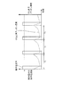
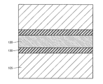
- FIG. 9 is a schematic cross-sectional view showing an example of an alkaline fuel cell that can be provided in the fuel cell unit 10a in the present embodiment, and FIGS. 10 and 11 are respectively an XX line and an XI-XI line shown in FIG. It is a schematic sectional drawing in a line.
- the alkaline fuel cell shown in FIG. 9 includes a membrane electrode assembly (MEA) 3.
- MEA membrane electrode assembly
- the membrane electrode assembly 3 includes an anion conductive electrolyte membrane 101; a first electrode (anode electrode) 103 laminated on the first surface of the anion conductive electrolyte membrane 101; and a first surface of the anion conductive electrolyte membrane 101.
- a second electrode (cathode electrode) 102 stacked on the second surface and a third electrode 110 for self-purge stacked on the first surface spaced apart from the first electrode 103 are mainly configured.
- a gasket 106 (for example, a layer made of an elastic resin such as silicone rubber or a cured resin layer of a curable resin such as an epoxy resin) is provided at the periphery of the electrode to prevent intrusion of air or the like from the electrode end face. Is provided.
- the first electrode 103 and the second electrode 102 are provided to face each other with the anion conductive electrolyte membrane 101 interposed therebetween. Such an opposing arrangement makes the distance between the first electrode 103 and the second electrode 102 the shortest, thereby reducing the resistance when a current flows between these electrodes, thus reducing the power generation efficiency. It is advantageous for suppression.
- the first electrode 103 is divided into two and laminated, and the third electrode 110 is separated from the first electrode 103 between the two first electrodes 103. Is arranged.
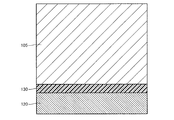
- the alkaline fuel cell shown in FIG. 9 includes a first current collecting layer 105 laminated on the first electrode 103; a second current collecting layer 104 laminated on the second electrode 102; and a third electrode.
- the third current collecting layer 120 is stacked on the 110. These current collecting layers are members for exchanging electrons with an electrode in contact with the current collecting layer and for performing electrical wiring.
- the first current collecting layer 105 and the third current collecting layer 120 are electrically insulated from each other by interposing an insulating layer 130 between these current collecting layers.
- the first current collecting layer 105 and the third current collecting layer 120 are provided with a first flow path 105 a for supplying a reducing agent to the first electrode 103 or the third electrode 110.
- each current collecting layer is also a member for supplying a reducing agent and an oxidizing agent.
- the constituent materials of the anion conductive electrolyte membrane 101, the first electrode 103, and the second electrode 102 of the alkaline fuel cell used in the present embodiment are the same as those of the alkaline fuel cell used in the first embodiment. be able to.
- the first electrode 103 and the second electrode 102 are preferably formed to have as large an area as possible on the anion conductive electrolyte membrane 101 from the viewpoint of improving the output per unit area of the fuel cell.
- the anion conductive electrolyte membrane 101 is preferably formed to have the same length or the same length.
- the third electrode 110 is an electrode for Serufupaji, an oxidizing agent supply to the supply and the second electrode 102 of the reducing agent to the third electrode 110 is an electrode for discharging CO 2 from anionic as CO 2 gas.
- the contents described above for the first electrode 103 in the first embodiment are cited.
- the third electrode 110 is disposed on the first surface of the anion conductive electrolyte membrane 101 so as to be separated from the first electrode 103 in order to function independently for self-purging.
- the first electrode 103 is divided into two parts, and the third electrode 110 is formed between them in the central region of the first surface of the anion conductive electrolyte membrane 101.
- the present invention is not limited to such an arrangement.
- the number of the first electrodes 103 (the presence or absence of division) and the positions of the third electrodes 110 are such that the third electrode 110 is arranged on the side of the first electrode 103 without dividing the first electrode 103.
- the ratio between the area (width ⁇ length) of the first electrode 103 and the area of the third electrode 110 is determined in consideration of both the power generation capability of the fuel cell and the self-purge efficiency. If the ratio (the area of the first electrode 103 / the area of the third electrode 110) is too large, the third electrode 110 is too small and the self-purging efficiency is lowered. On the other hand, if the ratio is too small, the first electrode 103 serving as the anode electrode that contributes to power generation is too small to obtain a sufficient output.
- the length of the third electrode 110 is preferably long so that CO 2 -derived anions can be taken from as wide a range as possible of the anion conductive electrolyte membrane 101. For example, the anion conductive electrolyte membrane 101 Or substantially the same length (see FIG. 10).
- the thickness of the first electrode 103 and the thickness of the third electrode 110 are preferably the same.
- the first current collecting layer 105, the second current collecting layer 104, and the third current collecting layer 120 are provided on and in contact with the first electrode 103, the second electrode 102, and the third electrode 110, respectively. It is a member for transferring electrons and performing electrical wiring. In the alkaline fuel cell shown in FIG. 9, these current collecting layers also have a function of supplying a reducing agent and an oxidizing agent.
- the first current collecting layer 105 and the third current collecting layer 120 include: A first flow path 105 a for supplying a reducing agent to the first electrode 103 and the third electrode 110 is provided in the second current collecting layer 104, and a second flow path 104 a for supplying an oxidant to the second electrode 102. Is provided.
- the first current collecting layer 105 and the third current collecting layer 120 are electrically insulated from each other by interposing the insulating layer 130 between these current collecting layers.
- the insulating layer 130 is not particularly limited as long as it exhibits electrical insulation, and can be made of, for example, various nonconductive polymers (including insulating adhesives).
- the material of the current collecting layer is not particularly limited, and for example, a conductive material such as a carbon material, a conductive polymer, various metals, and an alloy typified by stainless steel can be used.
- the material of each current collecting layer may be the same or different.
- the first flow path 105a and the second flow path 104a can be composed of one or more grooves provided on the electrode-side surface of the current collecting layer, and the shape thereof is not particularly limited, and is linear or serpentine Etc.
- the flow path for supplying the reducing agent to the first electrode 103 and the flow path for supplying the reducing agent to the third electrode 110 may or may not be connected.
- a separate member (channel plate) for supplying the reducing agent and the oxidizing agent may be laminated on the current collecting layer.
- the flow path plate may be one in which one or more grooves are provided on the surface of a plate-like body made of a non-conductive material such as various plastic materials.
- FIG. 12 is a schematic cross-sectional view showing another example of an alkaline fuel cell that can be provided in the fuel cell unit 10a in the present embodiment, and FIGS. 13 and 14 are XIII-XIII line and XIV shown in FIG. 12, respectively. It is a schematic sectional drawing in the -XIV line.
- the alkaline fuel cell shown in FIG. 12 is characterized by including a membrane electrode assembly 4 having a plurality of self-purge third electrodes 110 (three in the example of FIG. 12) (see FIGS. 12 and 13).
- the other configuration can be the same as that of the alkaline fuel cell shown in FIG. 9 (possible modifications are the same as those of the alkaline fuel cell shown in FIG. 9).
- the membrane electrode assembly 4 includes an anion conductive electrolyte membrane 101; a first electrode 103 laminated on the first surface of the anion conductive electrolyte membrane 101; a second electrode laminated on the second surface of the anion conductive electrolyte membrane 101. 102; and three third electrodes 110 that are separated from the first electrode 103 and stacked on the first surface.
- the first electrode 103 and the second electrode 102 are provided so as to face each other with the anion conductive electrolyte membrane 101 interposed therebetween.
- the first electrode 103 is divided into two layers and laminated, and the total between the two first electrodes 103 and the outer sides of the two first electrodes 103 are separated from the first electrode 103 in total.
- Three third electrodes 110 are arranged.
- the alkaline fuel cell shown in FIG. 12 includes a first current collecting layer 105 (two in total) laminated on the first electrode 103; a second current collecting layer 104 laminated on the second electrode 102; A third current collecting layer 120 (three in total) is provided on the third electrode 110.
- the first current collecting layer 105 and the third current collecting layer 120 are electrically insulated from each other by interposing an insulating layer 130 between these current collecting layers.
- the first current collecting layer 105 and the third current collecting layer 120 are provided with a first flow path 105a for supplying a reducing agent to the first electrode 103 or the third electrode 110, and the second current collecting layer 105a.
- the layer 104 is provided with a second flow path 104 a for supplying an oxidant to the second electrode 102.
- the plurality of third electrodes 110 are connected to the anion conductive electrolyte membrane 101. It is preferable to disperse and arrange substantially uniformly in the first surface. This is due to the following reason. Since the anion conductive electrolyte membrane 101 is very thin, the ion conduction resistance in the film thickness direction is very small compared to the ion conduction resistance in the in-plane direction.
- the self-purge when the self-purge is advanced, the movement of the CO 2 -derived anion occurs mainly between the anion conductive electrolyte membrane 101 in the vicinity of the third electrode 110 and the second electrode 102 and the third electrode 110, and the self-purge is preferential. Proceed to. On the other hand, since the ion conduction resistance is large between the anion conductive electrolyte membrane 101 and the second electrode 102 and the third electrode 110 in a region far from the third electrode 110, the movement of the CO 2 -derived anion hardly occurs, There is a tendency that self-purge does not progress sufficiently.
- the area in the vicinity of the third electrode 110 can be increased, whereby an anion conducting electrolyte membrane is obtained.
- the self-purge of the entire 101 and the second electrode 102 can be performed.
- the plurality of third electrodes 110 are preferably provided at positions facing the second electrodes 102.
- FIG. 15 is a schematic diagram illustrating a control device according to the present embodiment and an alkaline fuel cell system to which the control device is applied.
- the control device and the alkali are connected to an electronic device (electronic device 50) to which power is supplied.
- 1 shows the configuration of a fuel cell system.
- the control device and alkaline fuel cell system of this embodiment are the same as those of the third embodiment except that the current value changing unit 30 further includes a power supply device 30c in addition to the electronic load device 30a.
- the power supply device 30c is connected in series to the alkaline fuel cell of the fuel cell unit 10a via the switch 30b.
- the switch 30b plays a role of switching between the presence / absence of the power supply device 30c in the circuit connecting the electronic load device 30a and the fuel cell unit 10a.
- an alkaline fuel cell including the third electrode 110 for self-purge is used.
- a power supply device is used. Specifically, the control unit 40a operates the switch 30b to connect the power supply device 30c and the fuel cell unit 10a in series. Further, in some cases, the electromotive force of the power supply device 30c is increased and the electronic load device 30a flows. By increasing the load current, a current of a predetermined current value A or more is allowed to flow between the third electrode and the second electrode for a certain time T 2 such that T 2 / T 0 ⁇ W T.
- the time ratio T 1 / T 0 is constantly detected so that a cycle of unit time T 0 including a certain time during which a current of a predetermined current value A or more flows is repeated.
- the effects [i] to [vi] described above can also be achieved by the control device and alkaline fuel cell system of the present embodiment.
- FIG. 16 is a schematic diagram showing a control device according to the present embodiment and an alkaline fuel cell system to which the control device is applied.
- the control device and the alkali are connected to an electronic device (electronic device 50) to which power is supplied.
- 1 shows the configuration of a fuel cell system.
- the control device and alkaline fuel cell system of the present embodiment include the third electrode on the first electrode side and the fourth electrode on the second electrode side. It is the same as that of the said 1st Embodiment except using the alkaline fuel cell which has a membrane electrode composite further provided with an electrode for the fuel cell part 10a.
- These third electrode and fourth electrode are self-purge electrodes provided independently of the first electrode and the second electrode.
- the third electrode is laminated on the surface of the anion conductive electrolyte membrane on the same side as the first electrode that functions as the anode electrode during power generation, but is disposed apart from (not in contact with) the first electrode.
- the fourth electrode is laminated on the surface of the anion conductive electrolyte membrane on the same side as the second electrode functioning as a cathode electrode during power generation, but is disposed apart from (not in contact with) the second electrode.
- the unit time T in 0, the membrane electrode assembly - the ratio T 1 / T 0 (the first electrode and the second inter-electrode) to the time flows over the current predetermined current value A T 1 is predetermined
- the control unit 40a determines whether the time ratio is less than the time ratio W T , the control unit 40a determines whether the fuel cell unit 10a is generating power (supplying electric power to the electronic device 50) or not.
- the electronic load device 30a is controlled so that a current of a predetermined current value A or more flows between the third electrode and the fourth electrode for a predetermined time.
- a reducing agent is supplied to the third electrode and an oxidizing agent is supplied to the fourth electrode. while (or oxidizing agent to the third electrode, while supplying reducing agent to the fourth electrode), by increasing the load current flowing through the electronic load 30a by the control unit 40a, the T 2 / T 0 ⁇ W T During such a certain time T 2 , a current of a predetermined current value A or more is passed between the third electrode and the fourth electrode.
- the time ratio T 1 / T 0 is constantly detected so that a cycle of unit time T 0 including a certain time during which a current of a predetermined current value A or more flows is repeated.
- the value of the current that flows for a certain time (T 2 ) here is the value obtained by dividing the amount of current flowing between the third electrode and the fourth electrode by the projected area of the cathode electrode (second electrode) onto the electrolyte membrane.
- T 2 the value obtained by dividing the amount of current flowing between the third electrode and the fourth electrode by the projected area of the cathode electrode (second electrode) onto the electrolyte membrane.
- the present embodiment is different from the first embodiment in that a current of a predetermined current value A or more flows between the third electrode (for self-purging) and the fourth electrode (for self-purging) for a certain period of time. Is different. Further, the third embodiment is different from the third embodiment in which a current of a predetermined current value A or more flows between the third electrode (for self-purging) and the second electrode (cathode electrode) for a predetermined time.
- the alkaline fuel cell system of the present embodiment using the alkaline fuel cell having the third electrode and the fourth electrode has the following operational effects [vii].
- Can play That is, if a current of a predetermined current value A or more is allowed to flow between the third electrode and the fourth electrode, the amount of current flowing between the first electrode and the second electrode does not change, and between the first electrode and the second electrode. Therefore, the CO 2 -derived anion concentration can be reduced without reducing the power generation efficiency.
- the electronic load device 30a is connected to the third electrode and the fourth electrode so that a current of a predetermined current value A or more can flow between the third electrode and the fourth electrode of the membrane electrode assembly for a predetermined time.
- the first electrode and the second electrode that contribute to substantial power generation are connected to the electronic device 50 using a wiring different from the wiring that connects the third electrode and the fourth electrode to the electronic load device 30a (see FIG. 16).
- An ammeter for confirming whether or not a current greater than or equal to a predetermined current value A flows may be disposed between the membrane electrode assembly and the electronic load device 30a.
- FIG. 17 is a schematic cross-sectional view showing an example of an alkaline fuel cell that can be provided in the fuel cell unit 10a in the present embodiment.
- FIGS. 18 to 21 are XVIII-XVIII line and XIX-XIX shown in FIG.
- FIG. 4 is a schematic cross-sectional view taken along line XX-XX, XXI-XXI.
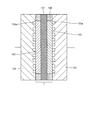
- the alkaline fuel cell shown in FIG. 17 includes a membrane electrode assembly (MEA) 5 having a fourth electrode 115 for self-purging in addition to the third electrode 110 for self-purging.
- MEA membrane electrode assembly
- the membrane electrode assembly 5 is laminated on the second surface of the anion conductive electrolyte membrane 101; the first electrode (anode electrode) 103 laminated on the first surface of the anion conductive electrolyte membrane 101; A second electrode (cathode electrode) 102; a third electrode 110 stacked on the first surface spaced apart from the first electrode 103; and a fourth electrode stacked on the second surface spaced apart from the second electrode 102.
- 115 is mainly composed.
- a gasket 106 is provided on the periphery of the electrode.
- the first electrode 103 and the second electrode 102 are provided so as to face each other with the anion conductive electrolyte membrane 101 interposed therebetween.
- the alkaline fuel cell shown in FIG. 17 includes a first current collecting layer 105 laminated on the first electrode 103; a second current collecting layer 104 laminated on the second electrode 102; A third current collecting layer 120; and a fourth current collecting layer 125 laminated on the fourth electrode 115.
- the first current collecting layer 105 and the third current collecting layer 120 are electrically insulated from each other by interposing an insulating layer 130 between these current collecting layers.
- the second current collecting layer 104 and the fourth current collecting layer 125 are electrically insulated from each other with the insulating layer 130 interposed therebetween.
- the first current collecting layer 105 and the third current collecting layer 120 are provided with a first flow path 105 a for supplying a reducing agent to the first electrode 103 or the third electrode 110.
- the second current collecting layer 104 and the fourth current collecting layer 125 are provided with a second flow path 104 a for supplying an oxidant to the second electrode 102 or the fourth electrode 115.
- each current collecting layer is also a member for supplying a reducing agent and an oxidizing agent.
- the constituent materials of the anion conductive electrolyte membrane 101, the first electrode 103, and the second electrode 102 of the alkaline fuel cell used in the present embodiment are the same as those of the alkaline fuel cell used in the first embodiment. be able to.
- the third electrode 110 and the fourth electrode 115 are self-purge electrodes, and by supplying the reducing agent to the third electrode 110 and the oxidizing agent to the fourth electrode 115, the CO 2 -derived anion is generated from the third electrode 110. It is discharged as CO 2 gas (when a reducing agent is supplied to the fourth electrode 115 and an oxidizing agent is supplied to the third electrode, CO 2 -derived anions are discharged from the fourth electrode 115 as CO 2 gas) .
- the configuration and composition of the third electrode 110 and the fourth electrode 115 the contents described above for the first electrode 103 are cited.
- the third electrode 110 is disposed on the first surface of the anion conductive electrolyte membrane 101 so as to be separated from the first electrode 103 in order to function independently for self-purging.
- the fourth electrode 115 is disposed on the second surface of the anion conductive electrolyte membrane 101 so as to be separated from the second electrode 102 in order to function independently for self-purging.
- the third electrode 110 and the fourth electrode 115 are not provided so as to face each other with the anion conductive electrolyte membrane 101 interposed therebetween, but are arranged on one outer side of the first electrode 103.
- the fourth electrode 115 is preferably disposed on the outer side of the second electrode 102 opposite to the side facing the third electrode 110 with respect to the third electrode 110.
- the anion conductive electrolyte membrane 101 passes through a considerably wide area of the anion conductive electrolyte membrane 101 (when the third electrode 110 and the fourth electrode 115 are disposed at almost the end of the membrane electrode assembly). Self-purging can be performed for most regions of the anion conductive electrolyte membrane 101).
- the arrangement configuration of the third electrode 110 and the fourth electrode 115 and the shape of these electrodes are not limited to those shown in the figure, and the shortest path from the third electrode 110 to the fourth electrode 115 is the same as that of the first electrode 103.
- FIG. 22 is a schematic diagram showing a control device according to the present embodiment and an alkaline fuel cell system to which the control device is applied.
- the control device and the alkali are connected to an electronic device (electronic device 50) to which power is supplied.
- 1 shows the configuration of a fuel cell system.
- the control device and the alkaline fuel cell system of this embodiment are the same as those of the fifth embodiment except that the current value changing unit 30 further includes a power supply device 30c in addition to the electronic load device 30a.
- the power supply device 30c is connected in series to the alkaline fuel cell of the fuel cell unit 10a via the switch 30b.
- the switch 30b plays a role of switching between the presence / absence of the power supply device 30c in the circuit connecting the electronic load device 30a and the fuel cell unit 10a.
- an alkaline fuel cell including the third electrode 110 and the fourth electrode 115 for self-purging is used.
- the driving force for forcing a current of a predetermined current value A or more to flow through the membrane electrode assembly is not used.
- a power supply device is used.
- the control unit 40a operates the switch 30b to connect the power supply device 30c and the fuel cell unit 10a in series. Further, in some cases, the electromotive force of the power supply device 30c is increased and the electronic load device 30a flows. By increasing the load current, a current of a predetermined current value A or more is allowed to flow between the third electrode and the fourth electrode for a certain time T 2 such that T 2 / T 0 ⁇ W T.
- the time ratio T 1 / T 0 is constantly detected so that a cycle of unit time T 0 including a certain time during which a current of a predetermined current value A or more flows is repeated.
- the effects [i] to [vii] described above can also be achieved by the control device and alkaline fuel cell system of the present embodiment.
- the detection unit 20 is in the state of “alkaline fuel cell” [a] The ratio T 1 / T of the time T 1 during which a current greater than or equal to the predetermined current value A flows in the membrane electrode assembly within a unit time T 0 .
- the detection unit 20 detects any of the above-mentioned [b] to [e] as “the state of the alkaline fuel cell” Even in such a case, the same effect can be obtained.
- the concentration is detected by the detection unit 20. If it is detected constantly or at regular intervals and it is determined that the concentration exceeds a predetermined concentration, the control unit 40 applies a predetermined value to the membrane electrode assembly regardless of whether the fuel cell unit 10 is generating power.
- the current value changing unit 30 is controlled so that a current greater than or equal to the current value A flows for a certain time.
- the resistance value is constantly or constant by the detection unit 20 by a method such as current interrupt measurement or impedance measurement. If it is detected every hour and it is determined that the resistance value exceeds a predetermined resistance value, the control unit 40 determines whether the fuel cell unit 10 is generating power or not with a predetermined current in the membrane electrode assembly. The current value changing unit 30 is controlled so that a current equal to or greater than the value A flows for a certain time.
- the voltage value of the alkaline fuel cell is detected as “the state of the alkaline fuel cell”
- the voltage value is detected by the detection unit 20 (voltmeter connected to the MEA) at regular time intervals or at regular intervals. If it is determined that the obtained voltage / current characteristic is lower than the predetermined voltage / current characteristic (inferior to the predetermined voltage / current characteristic), the control unit 40 causes the fuel cell unit 10 to generate power. Regardless of whether or not it is performed, the current value changing unit 30 is controlled so that a current of a predetermined current value A or more flows through the membrane electrode assembly for a predetermined time.
- Example 1 A control device and an alkaline fuel cell system having the same configuration as in FIG.
- the catalyst-supported carbon particles (“TEC10E50E” manufactured by Tanaka Kikinzoku Co., Ltd.) having a Pt-supported amount of Pt / C of 50% by weight and the above-obtained electrolyte solution have a weight ratio of 2 / 0.2.
- a catalyst paste for the anode catalyst layer was prepared by mixing and further adding ion exchange water and ethanol.
- a catalyst-supporting carbon particle (“TEC10E50E” manufactured by Tanaka Kikinzoku Co., Ltd.) having a Pt support amount of 50% by weight and Pt / C and the electrolyte solution obtained above are 2 / 0.2 in weight ratio.
- the catalyst paste for the cathode catalyst layer was prepared by mixing the mixture as described above and further adding ion exchange water and ethanol.
- carbon paper (“TGP-H-060” manufactured by Toray Industries Inc., thickness of about 190 ⁇ m) is cut into a size of 23 mm in length and 23 mm in width as an anode gas diffusion layer.
- a catalyst paste for the anode catalyst layer was applied using a screen printing plate having a window of 23 mm in length and 23 mm in width so that the amount of catalyst was 0.5 mg / cm 2, and dried at room temperature.
- carbon paper (“TGP-H-060” manufactured by Toray Industries Inc., thickness of about 190 ⁇ m) is cut into a size of 23 mm in length ⁇ 23 mm in width as a cathode gas diffusion layer
- the cathode paste for the cathode catalyst layer was applied using a screen printing plate having a window of 23 mm in length and 23 mm in width so that the amount of catalyst was 0.5 mg / cm 2, and dried at room temperature.
- a cathode electrode (second electrode) in which a cathode catalyst layer was formed on the entire surface of one side of carbon paper as a gas diffusion layer was produced.
- the thickness of the obtained cathode electrode was about 200 ⁇ m.
- a fluororesin polymer electrolyte (“Aciplex” manufactured by Asahi Kasei Co., Ltd.) cut into a size of 50 mm ⁇ 50 mm is used as the anion conductive solid polymer electrolyte membrane, and the anode electrode, the electrolyte membrane, and the cathode electrode are used as the anion conductive solid polymer electrolyte membrane.
- the anode electrode and the cathode electrode are joined to the electrolyte membrane by thermocompression bonding at 130 ° C. and 10 kN for 2 minutes, and the membrane electrode composite Got the body.
- the superposition was performed so that the positions of the anode electrode and the cathode electrode in the plane of the electrolyte membrane coincided and the centers of the anode electrode, the electrolyte membrane, and the cathode electrode coincided.
- a fuel cell was produced by combining the membrane electrode assembly with a part obtained by disassembling a commercially available fuel cell (manufactured by Electrochem). Specifically, first, anode electrode side current collector (end plate) / carbon anode electrode separator (having a reducing agent supply channel (first channel)) / polytetrafluoroethylene gasket / Laminate in the order of membrane electrode composite / polytetrafluoroethylene gasket / carbon cathode electrode separator (equipped with an oxidizing agent supply channel (second channel)) / cathode electrode side current collector (end plate) did.
- anode electrode side current collector (end plate) / carbon anode electrode separator having a reducing agent supply channel (first channel)
- polytetrafluoroethylene gasket / Laminate in the order of membrane electrode composite / polytetrafluoroethylene gasket / carbon cathode electrode separator (equipped with an oxidizing agent supply channel (second channel)) / cathode electrode
- control device having the same configuration as that shown in FIG. 4 is manufactured, and the alkaline fuel cell manufactured as described above is used as the fuel cell unit 10a. Produced. Specifically, it is as follows.
- the reducing agent supply pipe is connected so that the reducing agent can be supplied to the anode separator of the fuel cell unit 10a, and the oxidant supply pipe is connected so that the oxidizing agent can be supplied to the cathode electrode separator of the fuel cell unit 10a.
- a charge / discharge battery system (“PFX2011” manufactured by Kikusui Electric Co., Ltd., an ammeter, a voltmeter, and an electronic load device are integrally provided) as the detection unit 20a and the electronic load device 30a is provided as an anode of the fuel cell unit 10a.
- the electrode side current collector and the cathode side electrode current collector were connected.
- the detection unit 20a detects a ratio T 1 / T 0 of time T 1 during which a current of a predetermined current value A or more flows between the first electrode and the second electrode of the membrane electrode assembly within the unit time T 0 .
- the control unit 40a includes a personal computer [time measuring means (timer) and storage means (memory) for storing current values and times T 0 and T 1 . Is connected to the charge / discharge battery system so that the detection result can be received, and control information can be transmitted to the charge / discharge battery system based on the detection result.
- Example 1 [Evaluation of power generation efficiency of alkaline fuel cells] (1)
- the control device (alkaline fuel cell system) of Example 1 in which the time T 2 is set to 1 minute, the operation of the fuel cell unit 10a (alkaline fuel cell) is stopped (current value 0 mA / cm 2 ).
- the control device (alkaline fuel cell system) of the first embodiment by operating the fuel cell unit 10a (alkaline fuel cell) at a current value of 100 mA / cm 2 , a current value of 100 mA / cm 2 (9 minutes) ) ⁇ current value 600 mA / cm 2 (1 minute) ⁇ current value 100 mA / cm 2 (9 minutes) ⁇ ...
- a current of 600 mA / cm 2 was forcibly passed through the membrane electrode assembly in a pattern of .
- the alkaline fuel cell system of Comparative Example 1 was operated at a current value of 100 mA / cm 2 for 2 hours without performing an operation of forcibly passing a current through the membrane electrode assembly, and then 200 mA / cm.
- the current of 2 was taken out, the power generation efficiency after 5 minutes was 35%, and it took 15 minutes to obtain the power generation efficiency of 50%.
- Membrane electrode assembly 10 10a Fuel cell unit, 20, 20a detection unit, 30 Current value change unit, 30a Electronic load device, 30b switch, 30c Power supply device, 40, 40a control unit 50, electronic equipment, 101, anion conductive electrolyte membrane, 102, second electrode, 103, first electrode, 104, second current collecting layer, 104a, second flow path, 105, first current collecting layer, 105a, first flow path, 106 gasket , 110 third electrode, 115 fourth electrode, 120 third current collecting layer, 125 fourth current collecting layer, 130 insulating layer.
Abstract
Provided is a control device including: a detecting unit for detecting the state of a fuel cell; a current-value changing unit for changing the current value passing through a membrane electrode assembly of the fuel cell; and a control unit that is connected to the detecting unit and the current-value changing unit and that is for controlling the current-value changing unit in a manner such that a current of a predetermined current value (A) or greater is passed through the membrane electrode assembly for a given amount of time in accordance with the result of detection by the detecting unit. Also provided is a fuel-cell system employing the control device. The fuel cell is preferably an alkaline fuel cell provided with a membrane electrode assembly employing an anion-conductive electrolyte membrane as an electrolyte membrane.
Description
本発明は、高い発電効率で燃料電池を稼動させることができる燃料電池の制御装置およびこれを用いた燃料電池システムに関する。
The present invention relates to a fuel cell control device capable of operating a fuel cell with high power generation efficiency and a fuel cell system using the same.
燃料電池は、発電主要部として、電解質膜をアノード極およびカソード極で挟持した構成の膜電極複合体(MEA)を備えており、電解質膜の種類によって、固体高分子形燃料電池(直接形燃料電池を含む)、リン酸形燃料電池、溶融炭酸塩形燃料電池、固体酸化物形燃料電池、アルカリ形燃料電池などに分類される。
The fuel cell includes a membrane electrode assembly (MEA) having a configuration in which an electrolyte membrane is sandwiched between an anode and a cathode as a main part of power generation. Depending on the type of electrolyte membrane, a polymer electrolyte fuel cell (direct fuel) Battery), phosphoric acid fuel cell, molten carbonate fuel cell, solid oxide fuel cell, alkaline fuel cell and the like.
上記のうち、アルカリ形燃料電池は、電解質膜としてアニオン伝導性電解質膜(アニオン交換膜)を用いた、電荷キャリアが水酸化物イオン(OH-)である燃料電池である。アルカリ形燃料電池においては、アノード極とカソード極とを電気的に接続すると、次のような電気化学反応によりアノード極とカソード極との間に電流が流れ、電気エネルギーを得ることができる。すなわち、カソード極に酸化剤(たとえば酸素または空気など)および水(この水は、アノード極で生じ、電解質膜を透過した水であり得る)を供給すると、下記式(1):
カソード極:1/2O2+H2O+2e‐ → 2OH- (1)
で表される触媒反応によりOH-が生成される。このOH-は、水分子との水和状態で電解質膜を介してアノード極側に伝達される。一方、アノード極では、供給された還元剤(燃料)、たとえばH2ガスとカソード極から伝達されたOH-とが、下記式(2):
アノード極:H2+2OH- → 2H2O+2e‐ (2)
で表される触媒反応を起こし、水および電子を生成する。 Among the above, the alkaline fuel cell is a fuel cell in which an anion conductive electrolyte membrane (anion exchange membrane) is used as an electrolyte membrane, and charge carriers are hydroxide ions (OH − ). In an alkaline fuel cell, when an anode electrode and a cathode electrode are electrically connected, a current flows between the anode electrode and the cathode electrode by the following electrochemical reaction, and electric energy can be obtained. That is, when an oxidizing agent (for example, oxygen or air) and water (this water may be water generated at the anode electrode and permeated through the electrolyte membrane) are supplied to the cathode electrode, the following formula (1):
Cathode electrode: 1 / 2O 2 + H 2 O + 2e − → 2OH − (1)
OH − is generated by the catalytic reaction represented by This OH − is transmitted to the anode side through the electrolyte membrane in a hydrated state with water molecules. On the other hand, in the anode electrode, the supplied reducing agent (fuel), for example, H 2 gas and OH − transmitted from the cathode electrode are expressed by the following formula (2):
Anode electrode: H 2 + 2OH − → 2H 2 O + 2e − (2)
To generate water and electrons.
アルカリ形燃料電池は、触媒などの構成材料の制限が少なく、より安価に製造できるなどの利点を有している一方、他の燃料電池と異なり、電解質膜および触媒層の電解質にアニオン伝導性電解質を用いるために、電解質膜および触媒層が環境中の二酸化炭素(CO2)を吸収し、電解質膜および触媒層中のOH-が、下記式(3)および(4):
CO2+2OH- → CO3 2-+H2O (3)
CO2+OH- → HCO3 - (4)
のような反応によってCO3 2-および/またはHCO3 -(以下、「CO2由来アニオン」ということがある。)に置換されやすいという本来的な課題を有している。このようなCO2由来アニオンの濃度上昇(OH-イオン濃度の低下)は、電解質のアニオン伝導度を低下させ、結果、セル抵抗を大きく増大させるため、発電効率の低下を招く。 Alkaline fuel cells have advantages such as fewer restrictions on constituent materials such as catalysts and can be manufactured at a lower cost, but unlike other fuel cells, the electrolyte of the electrolyte membrane and catalyst layer is an anion conductive electrolyte. Therefore, the electrolyte membrane and the catalyst layer absorb carbon dioxide (CO 2 ) in the environment, and OH − in the electrolyte membrane and the catalyst layer is represented by the following formulas (3) and (4):
CO 2 + 2OH − → CO 3 2− + H 2 O (3)
CO 2 + OH - → HCO 3 - (4)
It has an inherent problem that it is easily replaced by CO 3 2− and / or HCO 3 − (hereinafter sometimes referred to as “CO 2 -derived anion”) by such a reaction. Such an increase in the concentration of the CO 2 -derived anion (decrease in the OH − ion concentration) decreases the anion conductivity of the electrolyte and, as a result, greatly increases the cell resistance, leading to a decrease in power generation efficiency.
上記セル抵抗増大の問題は、アルカリ形燃料電池の稼動により生じる「セルフパージ」と呼ばれる現象により改善できることが知られている〔たとえば、Hiroyuki Yanagi,and Kenji Fukuta,ECS Transactions,16(2),257-262(2008)(非特許文献1)〕。
It is known that the problem of increase in cell resistance can be improved by a phenomenon called “self-purge” caused by operation of an alkaline fuel cell [for example, Hiroyuki Yanagi, and Kenji Fukuta, ECS Transactions, 16 (2), 257- 262 (2008) (Non-Patent Document 1)].
「セルフパージ」とは、アルカリ形燃料電池の稼動により、アニオン伝導度の低下の要因である、電解質膜および触媒層に含まれるCO2由来アニオンがアノード極に移動し、還元剤によって還元され、CO2ガスとしてアノード極から排出される現象をいい、具体的には下記式(5)および(6):
H2+CO3 2- → CO2+H2O+2e- (5)
H2+2HCO3 - → 2CO2+2H2O+2e- (6)
で表すことができる。 “Self-purge” refers to the cause of a decrease in anion conductivity due to the operation of an alkaline fuel cell. The CO 2 -derived anion contained in the electrolyte membrane and the catalyst layer moves to the anode electrode and is reduced by the reducing agent. This refers to the phenomenon of being discharged from the anode electrode as two gases. Specifically, the following formulas (5) and (6):
H 2 + CO 3 2− → CO 2 + H 2 O + 2e − (5)
H 2 + 2HCO 3 − → 2CO 2 + 2H 2 O + 2e − (6)
Can be expressed as
ところで、アルカリ形燃料電池に限らず、燃料電池の発電電力を有効に利用するためには、当該燃料電池を電力源とする電子機器の電力消費量に応じて、燃料電池の発電量を調整する必要がある。たとえば、電子機器の電力消費が無い場合には、燃料電池の稼動(発電)を停止したり、電子機器の電力消費が小さい場合には、燃料電池の発電量(すなわち、動作電流値)を小さくしたり、電力消費が大きい場合には、燃料電池の発電量を大きくしたりする必要がある。
By the way, in order to effectively use the power generated by the fuel cell, not limited to the alkaline fuel cell, the power generation amount of the fuel cell is adjusted according to the power consumption of the electronic device using the fuel cell as a power source. There is a need. For example, when there is no power consumption of the electronic device, the operation (power generation) of the fuel cell is stopped, or when the power consumption of the electronic device is small, the power generation amount (that is, the operating current value) of the fuel cell is decreased. If the power consumption is large, it is necessary to increase the power generation amount of the fuel cell.
しかしながら、アルカリ形燃料電池においては、電子機器の電力消費量に応じて稼動停止したり、動作電流値を小さくしたりすると、セルフパージによるアノード極からのCO2ガスの排出が十分に進行せず、セル抵抗増大による発電効率の低下を十分に抑制することができない。また、アノード極へのCO2由来アニオンの蓄積が進行することにより、アノード極における反応過電圧が高くなるという問題もある。反応過電圧の増大も発電効率を増大させる要因となる〔Yu Matsui,Morihiro Saito,Akimasa Tasaka,and Minoru Inaba,ECS Transactions,25(13),105-110(2010)(非特許文献2)参照〕。
However, in alkaline fuel cells, if the operation is stopped according to the power consumption of the electronic device or the operating current value is reduced, the discharge of CO 2 gas from the anode electrode by self-purge does not proceed sufficiently, A decrease in power generation efficiency due to an increase in cell resistance cannot be sufficiently suppressed. There is also a problem that the reaction overvoltage at the anode electrode increases due to the accumulation of CO 2 -derived anions on the anode electrode. An increase in reaction overvoltage is also a factor that increases power generation efficiency (see Yu Matsui, Morihiro Saito, Akimasa Tasaka, and Minoru Inaba, ECS Transactions, 25 (13), 105-110 (2010) (Non-Patent Document 2)).
本発明は上記課題に鑑みなされたものであり、その目的は、高い発電効率で燃料電池を稼動させることができる燃料電池の制御装置およびこれを用いた燃料電池システムを提供することにある。
The present invention has been made in view of the above problems, and an object of the present invention is to provide a fuel cell control device capable of operating a fuel cell with high power generation efficiency and a fuel cell system using the same.
本発明は、燃料電池の状態を検出するための検出部と、該燃料電池の膜電極複合体に流れる電流値を変更するための電流値変更部と、検出部および電流値変更部に接続され、検出部による検出結果に応じて、膜電極複合体に所定電流値A以上の電流が一定時間流れるように電流値変更部を制御するための制御部とを備える制御装置を提供する。燃料電池は、好ましくはアニオン伝導性電解質膜を電解質膜とする膜電極複合体を備えるアルカリ形燃料電池である。また、所定電流値Aは、たとえば600~1000mA/cm2の範囲内である。
The present invention is connected to a detection unit for detecting the state of the fuel cell, a current value changing unit for changing a current value flowing through the membrane electrode assembly of the fuel cell, a detection unit and a current value changing unit. A control device is provided that includes a control unit for controlling the current value changing unit so that a current equal to or greater than a predetermined current value A flows through the membrane electrode assembly for a certain period of time according to the detection result of the detection unit. The fuel cell is preferably an alkaline fuel cell comprising a membrane electrode assembly having an anion conductive electrolyte membrane as an electrolyte membrane. The predetermined current value A is in the range of 600 to 1000 mA / cm 2 , for example.
検出部は、好ましくは単位時間T0内における、膜電極複合体に所定電流値A以上の電流が流れた時間T1の割合T1/T0を検出するものである。
The detection unit preferably detects a ratio T 1 / T 0 of time T 1 during which a current equal to or greater than a predetermined current value A flows through the membrane electrode assembly within unit time T 0 .
電流値変更部は、アルカリ形燃料電池に接続される電子負荷装置または可変抵抗器を少なくとも備えるものであることができる。また、電流値変更部は、アルカリ形燃料電池に接続される電子負荷装置または可変抵抗器と、アルカリ形燃料電池に対して直列に接続される電源装置とを含むものであってもよい。
The current value changing unit may include at least an electronic load device or a variable resistor connected to the alkaline fuel cell. Further, the current value changing unit may include an electronic load device or a variable resistor connected to the alkaline fuel cell and a power supply device connected in series to the alkaline fuel cell.
本発明の1つの好ましい実施形態において、膜電極複合体は、アニオン伝導性電解質膜と、アニオン伝導性電解質膜の第1表面に積層される第1電極と、アニオン伝導性電解質膜の第1表面に対向する第2表面に積層される第2電極とからなり、検出部は、単位時間T0内における、第1電極と第2電極との間に所定電流値A以上の電流が流れた時間T1の割合T1/T0を検出するものであり、電流値変更部は、第1電極と第2電極との間に流れる電流値を変更するものであり、制御部は、検出部による検出結果に応じて、第1電極と第2電極との間に所定電流値A以上の電流が一定時間流れるように電流値変更部を制御するものである。第1電極は発電時におけるアノード極であり、第2電極は発電時におけるカソード極であることができる。
In one preferred embodiment of the present invention, the membrane electrode assembly includes an anion conductive electrolyte membrane, a first electrode laminated on the first surface of the anion conductive electrolyte membrane, and a first surface of the anion conductive electrolyte membrane. The detection unit has a time during which a current of a predetermined current value A or more flows between the first electrode and the second electrode within the unit time T 0 . is used to detect the ratio T 1 / T 0 of T 1, the current value changing unit is for changing the current flowing between the first electrode and the second electrode, the control unit, the detection unit According to the detection result, the current value changing unit is controlled so that a current of a predetermined current value A or more flows between the first electrode and the second electrode for a predetermined time. The first electrode may be an anode electrode during power generation, and the second electrode may be a cathode electrode during power generation.
本発明の他の好ましい実施形態において、膜電極複合体は、アニオン伝導性電解質膜と、アニオン伝導性電解質膜の第1表面に積層される第1電極と、アニオン伝導性電解質膜の第1表面に対向する第2表面に積層される第2電極と、第1電極と離間して第1表面に積層される第3電極とからなり、検出部は、単位時間T0内における、第1電極と第2電極との間に所定電流値A以上の電流が流れた時間T1の割合T1/T0を検出するものであり、電流値変更部は、第3電極と第2電極との間に流れる電流値を変更するものであり、制御部は、検出部による検出結果に応じて、第3電極と第2電極との間に所定電流値A以上の電流が一定時間流れるように電流値変更部を制御するものである。本実施形態においても、第1電極は発電時におけるアノード極であり、第2電極は発電時におけるカソード極であることができる。
In another preferred embodiment of the present invention, the membrane electrode assembly includes an anion conductive electrolyte membrane, a first electrode laminated on the first surface of the anion conductive electrolyte membrane, and a first surface of the anion conductive electrolyte membrane. The second electrode is stacked on the second surface opposite to the first electrode, and the third electrode is stacked on the first surface spaced apart from the first electrode. The detection unit includes the first electrode within the unit time T 0 . The ratio T 1 / T 0 of the time T 1 during which a current greater than or equal to the predetermined current value A flows between the first electrode and the second electrode is detected. The control unit is configured to change a current value that flows between the third electrode and the second electrode according to a detection result of the detection unit so that a current greater than or equal to a predetermined current value A flows for a certain period of time. The value changing unit is controlled. Also in this embodiment, the first electrode can be an anode electrode during power generation, and the second electrode can be a cathode electrode during power generation.
本発明のさらに他の好ましい実施形態において、膜電極複合体は、アニオン伝導性電解質膜と、アニオン伝導性電解質膜の第1表面に積層される第1電極と、アニオン伝導性電解質膜の第1表面に対向する第2表面に積層される第2電極と、第1電極と離間して第1表面に積層される第3電極と、第2電極と離間して第2表面に積層される第4電極とからなり、検出部は、単位時間T0内における、第1電極と第2電極との間に所定電流値A以上の電流が流れた時間T1の割合T1/T0を検出するものであり、電流値変更部は、第3電極と第4電極との間に流れる電流値を変更するものであり、制御部は、検出部による検出結果に応じて、第3電極と第4電極との間に所定電流値A以上の電流が一定時間流れるように電流値変更部を制御するものである。本実施形態においても、第1電極は発電時におけるアノード極であり、第2電極は発電時におけるカソード極であることができる。
In still another preferred embodiment of the present invention, the membrane electrode assembly includes an anion conductive electrolyte membrane, a first electrode laminated on a first surface of the anion conductive electrolyte membrane, and a first of the anion conductive electrolyte membrane. A second electrode stacked on the second surface facing the surface; a third electrode stacked on the first surface spaced apart from the first electrode; and a second electrode stacked on the second surface spaced apart from the second electrode. The detection unit detects the ratio T 1 / T 0 of the time T 1 during which a current of a predetermined current value A or more flows between the first electrode and the second electrode within the unit time T 0 . The current value changing unit changes a current value flowing between the third electrode and the fourth electrode, and the control unit changes the third electrode and the second electrode according to the detection result by the detecting unit. The current value changing unit is controlled so that a current of a predetermined current value A or more flows between the four electrodes for a predetermined time. Than is. Also in this embodiment, the first electrode can be an anode electrode during power generation, and the second electrode can be a cathode electrode during power generation.
本発明においては、アノード極としての第1電極が有する触媒層の体積を、カソード極としての第2電極が有する触媒層の体積より大きくすることも好ましい。
In the present invention, it is also preferable to make the volume of the catalyst layer of the first electrode as the anode electrode larger than the volume of the catalyst layer of the second electrode as the cathode electrode.
また、本発明は上記燃料電池を含む燃料電池部と、本発明に係る制御装置とを備える燃料電池システムを提供する。
The present invention also provides a fuel cell system comprising a fuel cell unit including the fuel cell and a control device according to the present invention.
本発明の制御装置および燃料電池システムによれば、高い発電効率で燃料電池を稼動させることができる。
According to the control device and the fuel cell system of the present invention, the fuel cell can be operated with high power generation efficiency.
図1は、本発明に係る制御装置およびこれを適用した燃料電池システムの構成を示す概略図である。図1に示されるように、本発明の制御装置は、燃料電池を含む燃料電池部10(燃料電池)に接続され、該燃料電池の状態を検出するための検出部20;燃料電池部10(燃料電池)に接続され、該燃料電池の膜電極複合体に流れる電流の電流値を変更するための電流値変更部30;および、検出部20と電流値変更部30とに接続される制御部40を基本的に備える。制御部40は、検出部20から燃料電池の状態に関する検出結果(情報信号)を受信し、受信した検出結果に応じて、膜電極複合体に所定電流値A以上の電流が一定時間流れるように電流値変更部30を制御する。
FIG. 1 is a schematic diagram showing a configuration of a control device according to the present invention and a fuel cell system to which the control device is applied. As shown in FIG. 1, the control device of the present invention is connected to a fuel cell unit 10 (fuel cell) including a fuel cell, and a detection unit 20 for detecting the state of the fuel cell; A current value changing unit 30 for changing a current value of a current flowing through the membrane electrode assembly of the fuel cell; and a control unit connected to the detecting unit 20 and the current value changing unit 30 40 is basically provided. The control unit 40 receives a detection result (information signal) related to the state of the fuel cell from the detection unit 20, and according to the received detection result, a current of a predetermined current value A or more flows through the membrane electrode assembly for a certain period of time. The current value changing unit 30 is controlled.
また、本発明の燃料電池システムは、燃料電池を含む燃料電池部10;燃料電池部10(燃料電池)に接続され、該燃料電池の状態を検出するための検出部20;燃料電池部10(燃料電池)に接続され、該燃料電池の膜電極複合体に流れる電流の電流値を変更するための電流値変更部30;および、検出部20と電流値変更部30とに接続される制御部40を基本的に備えている。燃料電池部10を構成する燃料電池は、好ましくはアニオン伝導性電解質膜を有する膜電極複合体を備えるアルカリ形燃料電池である。
The fuel cell system of the present invention includes a fuel cell unit 10 including a fuel cell; a detection unit 20 connected to the fuel cell unit 10 (fuel cell) and detecting the state of the fuel cell; A current value changing unit 30 for changing a current value of a current flowing through the membrane electrode assembly of the fuel cell; and a control unit connected to the detecting unit 20 and the current value changing unit 30 40 is basically provided. The fuel cell constituting the fuel cell unit 10 is preferably an alkaline fuel cell including a membrane electrode assembly having an anion conductive electrolyte membrane.
本発明の制御装置は、燃料電池の膜電極複合体に所定電流値A以上の電流が「一定時間」流れるように燃料電池を制御するものである。図2は燃料電池の膜電極複合体に、ある単位時間内における一定時間、所定電流値A以上の電流が流れるサイクルが繰り返されている状態を示した概念図である。図2を参照して説明すると、本発明において「膜電極複合体に所定電流値A以上の電流が一定時間流れる」とは、燃料電池がこれを電力源とする電子機器への電力供給を行なっているか(すなわち、発電しているか)否かに関わらず、単位時間T0内におけるある一定時間、所定電流値A以上の電流が流れていることを意味している。そして好ましくは、図2に示されるように、このような所定電流値A以上の電流が流れている一定時間を含む単位時間T0のサイクルが繰り返される。上記の「燃料電池がこれを電力源とする電子機器への電力供給を行なっているか(すなわち、発電しているか)否かに関わらず」とは、所定電流値A以上の電流が、電子機器からの要求に従った発電によるものか、制御装置が強制的に流したものであるかを問わないことを意味している。
The control device of the present invention controls the fuel cell so that a current of a predetermined current value A or more flows through the membrane electrode assembly of the fuel cell for a “certain time”. FIG. 2 is a conceptual diagram showing a state in which a cycle in which a current of a predetermined current value A or more flows for a certain period of time within a unit time is repeated in the fuel cell membrane electrode assembly. Referring to FIG. 2, in the present invention, “a current of a predetermined current value A or more flows through the membrane electrode assembly for a certain period of time” means that the fuel cell supplies power to an electronic device using this as a power source. This means that a current equal to or greater than the predetermined current value A flows for a certain period of time within the unit time T 0 regardless of whether or not the power is being generated (that is, whether or not power is being generated). Preferably, as shown in FIG. 2, a cycle of unit time T 0 including a certain time during which a current of a predetermined current value A or more flows is repeated. The above “regardless of whether or not the fuel cell supplies power to an electronic device using this as a power source (that is, whether or not it generates power)” means that a current of a predetermined current value A or more is an electronic device. This means that it does not matter whether it is due to power generation in accordance with a request from or whether the control device is forced to flow.
所定電流値A以上の電流が流れている一定時間を含む単位時間T0のサイクルが2回以上繰り返される場合において、上記一定時間はすべて同じ時間長さであってもよいし、2種以上の異なる時間長さを含んでいてもよい。また、膜電極複合体に流される電流は所定電流値A以上である限り特に制限されず、すべて同じ電流値であってもよいし、2種以上の異なる電流値を含んでいてもよい。単位時間T0内に所定電流値A以上の電流が複数回流されてもよい。
In the case where a cycle of unit time T 0 including a certain time during which a current of a predetermined current value A or more is flowing is repeated two or more times, all the above certain times may have the same time length, or two or more kinds Different time lengths may be included. Further, the current passed through the membrane electrode assembly is not particularly limited as long as it is equal to or greater than the predetermined current value A, and may all be the same current value or may include two or more different current values. A current greater than or equal to the predetermined current value A may be supplied a plurality of times within the unit time T 0 .
図2には、アルカリ形燃料電池の膜電極複合体に所定電流値A以上の電流が流れている一定時間を含む単位時間T0のサイクルが繰り返されている(所定電流値A以上の電流が間欠的に流れている)ときの、CO2由来アニオン濃度の変化の様子を併せて示している。図示されるように、所定電流値A以上の電流が流れている一定時間を含む単位時間T0のサイクルが繰り返されることにより、セルフパージが繰り返されるため、膜電極複合体中のCO2由来アニオン濃度を実質的に常に低い状態に維持することができ、CO2由来アニオンの蓄積を抑制することができる。これにより、セル抵抗増大およびアノード極における反応過電圧の上昇の問題が改善され、アルカリ形燃料電池の発電効率を向上させることができる。
In FIG. 2, a cycle of a unit time T 0 including a certain time during which a current of a predetermined current value A or more is flowing in the membrane electrode assembly of an alkaline fuel cell is repeated (a current of a predetermined current value A or more is The state of the change in the CO 2 -derived anion concentration when the gas flows intermittently is also shown. As shown in the figure, since the self-purge is repeated by repeating the cycle of the unit time T 0 including a certain time during which a current of a predetermined current value A or more flows, the CO 2 -derived anion concentration in the membrane electrode complex Can be maintained in a substantially low state, and accumulation of CO 2 -derived anions can be suppressed. As a result, the problems of an increase in cell resistance and an increase in reaction overvoltage at the anode electrode are improved, and the power generation efficiency of the alkaline fuel cell can be improved.
一方、図3は、アルカリ形燃料電池の膜電極複合体に所定電流値A以上の電流が流れている一定時間を含む単位時間T0が1つのみである(所定電流値A以上の電流が1回のみ流れる)ときの、CO2由来アニオン濃度の変化の様子を概念的に示したものである。このような場合とは、たとえば、制御装置によって所定電流値A以上の電流を強制的に流し、それ以降、制御装置および燃料電池の稼動を行なわない場合;制御装置によって所定電流値A以上の電流を強制的に流し、それ以降、所定電流値A未満の電流で燃料電池が発電を行なう場合;所定電流値A以上の電流で燃料電池が発電を行なった後、それ以降、所定電流値A未満の電流で燃料電池が発電を行なうか、または燃料電池の稼動を停止する場合などである。
On the other hand, FIG. 3 shows only one unit time T 0 including a certain time during which a current of a predetermined current value A or more flows through the membrane electrode assembly of an alkaline fuel cell (a current of a predetermined current value A or more is It shows conceptually how the CO 2 -derived anion concentration changes when it flows only once). In such a case, for example, when a current of a predetermined current value A or more is forcibly supplied by the control device and thereafter the control device and the fuel cell are not operated; a current of a predetermined current value A or more by the control device When the fuel cell generates power at a current lower than the predetermined current value A after that; after the fuel cell generates power at a current equal to or higher than the predetermined current value A, and thereafter This is the case when the fuel cell generates power with the current of or the operation of the fuel cell is stopped.
本発明における「膜電極複合体に所定電流値A以上の電流が一定時間流れる」とは、図3に示されるような場合、すなわち、所定電流値A以上の電流が流れている一定時間を含む単位時間T0が1つのみである場合を含み得るが、好ましくは図2に示されるように、このような単位時間T0のサイクルが繰り返される。膜電極複合体中のCO2由来アニオン濃度を実質的に常に低い状態に維持できるためである。所定電流値A以上の電流が流れている一定時間を含む単位時間T0が1つのみである場合には、当該単位時間T0後に燃料電池の発電を行なう際、十分に高い発電効率が得られないおそれがある。ただし、発電効率を顕著に低下させる程度にまでCO2由来アニオンが電解質膜および触媒層中に蓄積された後に燃料電池の発電を行なわないような場合には、所定電流値A以上の電流が流れている一定時間を含む単位時間T0が1つのみであってもよい。
In the present invention, “a current of a predetermined current value A or more flows through the membrane electrode assembly for a certain period of time” includes a case where the current of a predetermined current value A or more flows as shown in FIG. Although there may be a case where there is only one unit time T 0 , such a cycle of unit time T 0 is preferably repeated as shown in FIG. This is because the CO 2 -derived anion concentration in the membrane electrode complex can be maintained substantially always low. When there is only one unit time T 0 including a certain time during which a current equal to or greater than the predetermined current value A flows, sufficiently high power generation efficiency is obtained when the fuel cell generates power after the unit time T 0. There is a risk of not being able to. However, in the case where the fuel cell does not generate power after the CO 2 -derived anion is accumulated in the electrolyte membrane and the catalyst layer to such an extent that the power generation efficiency is significantly reduced, a current of a predetermined current value A or more flows. There may be only one unit time T 0 including a certain time.
すなわち、付随効果も含めて、本発明の制御装置およびこれを適用した燃料電池システム(とりわけ、アルカリ形燃料電池システム)は次のような作用効果を奏し得る。
That is, including the accompanying effects, the control device of the present invention and the fuel cell system (particularly an alkaline fuel cell system) to which the control device is applied can have the following operational effects.
〔i〕上記のとおり、燃料電池が発電しているか否か(換言すれば、燃料電池を電力源とする電子機器の電力消費量)に関わらず、膜電極複合体中のCO2由来アニオン濃度を実質的に常に低くした状態に維持することができるため、セル抵抗増大およびアノード極における反応過電圧の上昇を抑制した状態で燃料電池(アルカリ形燃料電池)を発電させることができ、もって発電効率を向上させることができる。
[I] As described above, regardless of whether or not the fuel cell is generating electricity (in other words, the power consumption of the electronic device using the fuel cell as a power source), the CO 2 -derived anion concentration in the membrane electrode assembly Can be maintained in a state that is always kept low, so that a fuel cell (alkaline fuel cell) can be generated in a state in which an increase in cell resistance and an increase in reaction overvoltage at the anode electrode are suppressed. Can be improved.
〔ii〕膜電極複合体中のCO2由来アニオン濃度を低くした状態で燃料電池(アルカリ形燃料電池)の稼動を停止することができ、また、停止中においても、CO2由来アニオン濃度を低くした状態に維持できるため、燃料電池(アルカリ形燃料電池)を起動する際の立ち上げ(立ち上げ時間)を早くすることができる(すなわち、要求される発電量に達するまでの時間を短くすることができる)。
[Ii] The operation of the fuel cell (alkaline fuel cell) can be stopped in a state where the CO 2 -derived anion concentration in the membrane electrode assembly is low, and the CO 2 -derived anion concentration is low even during the stoppage. Therefore, the start-up time (start-up time) when starting the fuel cell (alkaline fuel cell) can be shortened (that is, the time required to reach the required power generation amount is shortened) Is possible).
〔iii〕単位時間T0内におけるある一定時間、動作電流値を大きくするよう制御するため、連続的に動作電流値を大きくする場合と比べて、余剰電力(電子機器が要求する量を超える電力)の発生を抑制することができる。このことも発電効率の向上に寄与する。なお、当該余剰電力に起因する発電効率の低下を抑制するために、余剰電力をたとえば図示しない蓄電池などに蓄電してもよい。
[Iii] Since control is performed to increase the operating current value for a certain period of time within the unit time T 0 , the surplus power (power exceeding the amount required by the electronic device) is compared with the case where the operating current value is continuously increased. ) Can be suppressed. This also contributes to the improvement of power generation efficiency. In order to suppress a decrease in power generation efficiency due to the surplus power, the surplus power may be stored in, for example, a storage battery (not shown).
〔iv〕単位時間T0内におけるある一定時間、動作電流値を大きくするよう制御するため、このような制御を一切行なわない場合と比べて、燃料電池からの発熱量を増加させることができる。これにより、補助熱源を利用しなくても燃料電池の動作温度を適温に維持することができるようになる。このこともまた、発電効率の向上および立ち上げ時間の短縮化に寄与する。
[Iv] Since the control is performed so that the operating current value is increased for a certain period of time within the unit time T 0 , the amount of heat generated from the fuel cell can be increased as compared with the case where such control is not performed at all. As a result, the operating temperature of the fuel cell can be maintained at an appropriate temperature without using an auxiliary heat source. This also contributes to improvement of power generation efficiency and shortening of startup time.
〔v〕単位時間T0内におけるある一定時間、動作電流値を大きくするよう制御するため、このような制御を一切行なわない場合と比べて、アルカリ形燃料電池のアノード極における生成水量を増加させることができる〔上記式(2)参照〕。これにより、アニオン伝導性電解質膜の含水量を高く維持してそのアニオン伝導抵抗を低く維持することができるようになる。このこともまた、発電効率の向上および立ち上げ時間の短縮化に寄与する。
[V] Since the control is performed so that the operating current value is increased for a certain period of time within the unit time T 0 , the amount of water generated at the anode electrode of the alkaline fuel cell is increased as compared with the case where no such control is performed. [Refer to the above formula (2)]. As a result, the water content of the anion conductive electrolyte membrane can be kept high and the anion conduction resistance can be kept low. This also contributes to improvement of power generation efficiency and shortening of startup time.
また本発明において、検出部20によって検出される「燃料電池の状態」とは、膜電極複合体中のCO2由来アニオン濃度を評価することができる指標(パラメータ)を指しており、アルカリ形燃料電池に関し、具体的には次のものを挙げることができる。
In the present invention, “the state of the fuel cell” detected by the detection unit 20 refers to an index (parameter) that can evaluate the CO 2 -derived anion concentration in the membrane electrode assembly. Specific examples of the battery include the following.
〔a〕ある単位時間T0内における、膜電極複合体に所定電流値A以上の電流が流れた時間T1の割合T1/T0、
〔b〕アニオン伝導性電解質膜中のCO2由来アニオン濃度(またはこのうちのCO3 2-濃度)、
〔c〕アニオン伝導性電解質膜のpH、
〔d〕アニオン伝導性電解質膜の抵抗値、
〔e〕アルカリ形燃料電池の出力電圧値。 [A] is in the unit time T in 0, the ratio T 1 / T 0 of the time predetermined current value A or more current flows through the membrane electrode assembly T 1,
[B] CO 2 -derived anion concentration (or CO 3 2− concentration of these) in the anion conductive electrolyte membrane,
[C] pH of the anion conductive electrolyte membrane,
[D] resistance value of the anion conductive electrolyte membrane,
[E] Output voltage value of alkaline fuel cell.
上記のなかでも、膜電極複合体中のCO2由来アニオン濃度に影響を与える指標であるとともに、検出手法が比較的容易であることから、検出部20は上記〔a〕を検出するものであることが好ましい。
Among these, the detection unit 20 detects [a] because it is an index that affects the CO 2 -derived anion concentration in the membrane electrode complex and the detection method is relatively easy. It is preferable.
以下、実施の形態を示して本発明の制御装置および燃料電池システムについてより詳細に説明する。後述する実施形態はいずれもアルカリ形燃料電池を制御する制御装置およびこれを適用したアルカリ形燃料電池システムに係り、アルカリ形燃料電池の状態として上記〔a〕を検出するものである。
Hereinafter, the control device and the fuel cell system of the present invention will be described in more detail with reference to embodiments. Each of the embodiments described later relates to a control device for controlling an alkaline fuel cell and an alkaline fuel cell system to which the control device is applied, and detects the above [a] as the state of the alkaline fuel cell.
<第1の実施形態>
図4は、本実施形態に係る制御装置およびこれを適用したアルカリ形燃料電池システムを示す概略図であり、電力が供給される電子機器(電子機器50)と接続された状態で制御装置およびアルカリ形燃料電池システムの構成を示したものである。本実施形態の制御装置は、アニオン伝導性電解質膜を有する膜電極複合体を備えるアルカリ形燃料電池を含む燃料電池部10としての燃料電池部10aに接続される、検出部20としての、上記〔a〕(ある単位時間T0内における、膜電極複合体に所定電流値A以上の電流が流れた時間T1の割合T1/T0)を検出する検出部20a;燃料電池部10aに接続されるとともに、電子機器50に対して並列に接続される、電流値変更部30としての、アルカリ形燃料電池の膜電極複合体に流れる電流の電流値を変更するための電子負荷装置30a;および、検出部20aと電子負荷装置30aとに接続され、検出部20aによる検出結果に応じて、膜電極複合体に所定電流値A以上の電流が一定時間流れるように電子負荷装置30aを制御するための制御部40aを備えている。 <First Embodiment>
FIG. 4 is a schematic diagram showing a control device according to the present embodiment and an alkaline fuel cell system to which the control device is applied. The control device and the alkali are connected to an electronic device (electronic device 50) to which power is supplied. 1 shows the configuration of a fuel cell system. The control device according to the present embodiment includes the above-describeddetection unit 20 connected to a fuel cell unit 10a as a fuel cell unit 10 including an alkaline fuel cell including a membrane electrode assembly having an anion conductive electrolyte membrane. a] Detection unit 20a for detecting (a ratio T 1 / T 0 of time T 1 in which a current equal to or greater than a predetermined current value A flows in the membrane electrode assembly within a certain unit time T 0 ); connected to the fuel cell unit 10a And an electronic load device 30a for changing the current value of the current flowing through the membrane electrode assembly of the alkaline fuel cell as the current value changing unit 30 connected in parallel to the electronic device 50; and The electronic load device 30a is connected to the detection unit 20a and the electronic load device 30a, and the electronic load device 30a is controlled so that a current of a predetermined current value A or more flows through the membrane electrode assembly for a predetermined time according to the detection result by the detection unit 20a. A control unit 40a is provided.
図4は、本実施形態に係る制御装置およびこれを適用したアルカリ形燃料電池システムを示す概略図であり、電力が供給される電子機器(電子機器50)と接続された状態で制御装置およびアルカリ形燃料電池システムの構成を示したものである。本実施形態の制御装置は、アニオン伝導性電解質膜を有する膜電極複合体を備えるアルカリ形燃料電池を含む燃料電池部10としての燃料電池部10aに接続される、検出部20としての、上記〔a〕(ある単位時間T0内における、膜電極複合体に所定電流値A以上の電流が流れた時間T1の割合T1/T0)を検出する検出部20a;燃料電池部10aに接続されるとともに、電子機器50に対して並列に接続される、電流値変更部30としての、アルカリ形燃料電池の膜電極複合体に流れる電流の電流値を変更するための電子負荷装置30a;および、検出部20aと電子負荷装置30aとに接続され、検出部20aによる検出結果に応じて、膜電極複合体に所定電流値A以上の電流が一定時間流れるように電子負荷装置30aを制御するための制御部40aを備えている。 <First Embodiment>
FIG. 4 is a schematic diagram showing a control device according to the present embodiment and an alkaline fuel cell system to which the control device is applied. The control device and the alkali are connected to an electronic device (electronic device 50) to which power is supplied. 1 shows the configuration of a fuel cell system. The control device according to the present embodiment includes the above-described
なお、図4では燃料電池部10aを、アルカリ形燃料電池が有する膜電極複合体の第1電極(たとえばアノード極)および第2電極(たとえばカソード極)のみを示す形で図示しているが、これは単に模式的に図示したに過ぎず、燃料電池部が有するアルカリ形燃料電池が採り得るより具体的な構造については後述の記載および後述の図面が参照される。図4と同様の制御装置およびアルカリ形燃料電池システムの概略図を示した他の図面についても同様である。
In FIG. 4, the fuel cell unit 10a is illustrated in a form showing only the first electrode (for example, the anode electrode) and the second electrode (for example, the cathode electrode) of the membrane electrode assembly included in the alkaline fuel cell. This is merely schematically illustrated, and the description below and the drawings below will be referred to for a more specific structure that the alkaline fuel cell of the fuel cell unit can take. The same applies to other drawings showing schematic views of the control device and alkaline fuel cell system similar to those in FIG.
本実施形態において検出部20aは、膜電極複合体に流れる電流値(より具体的には膜電極複合体の第1電極-第2電極間を流れる電流値)を測定するための、燃料電池部10a(アルカリ形燃料電池)に接続された電流計を少なくとも備えており、この電流計とともに、単位時間T0および膜電極複合体に所定電流値A以上の電流が流れた時間T1を測定するための時間測定手段(タイマーなど)ならびに、電流値および時間T0、T1を記憶する記憶手段(メモリなど)を具備することができる。ただし、時間測定手段および記憶手段は制御部40aに包含することもできる。
In the present embodiment, the detection unit 20a is a fuel cell unit for measuring a current value flowing through the membrane electrode assembly (more specifically, a current value flowing between the first electrode and the second electrode of the membrane electrode assembly). At least an ammeter connected to 10a (alkaline fuel cell) is provided, and together with this ammeter, a unit time T 0 and a time T 1 when a current of a predetermined current value A or more flows through the membrane electrode assembly are measured. Time measuring means (such as a timer) and storage means (such as a memory) for storing the current value and the times T 0 and T 1 can be provided. However, the time measuring means and the storage means can be included in the control unit 40a.
電子負荷装置30aとしては従来公知のものを使用することができ、可変抵抗器を使用することもできる。制御部40aとしては、検出部20aによる検出結果に応じて、膜電極複合体に所定電流値A以上の電流が一定時間流れるように電子負荷装置30aを制御できるものであれば特に制限されず、たとえばパーソナルコンピュータなどであることができる。
Conventionally known devices can be used as the electronic load device 30a, and a variable resistor can also be used. The controller 40a is not particularly limited as long as it can control the electronic load device 30a so that a current equal to or greater than the predetermined current value A flows through the membrane electrode assembly for a certain period of time according to the detection result by the detector 20a. For example, it can be a personal computer.
本実施形態において、検出部20aは上記時間割合T1/T0を好ましくは常時検出し、この時間割合T1/T0が所定の時間割合WT未満であると制御部40aによって判断された場合、制御部40aは、燃料電池部10aが発電(電子機器50への電力供給)を行なっているかに関わらず、膜電極複合体に(第1電極-第2電極間に)所定電流値A以上の電流が一定時間流れるよう(たとえば図2に示されるような電流波形パターンが得られるよう)電子負荷装置30aを制御する。
In this embodiment, the detection unit 20a preferably detects the time ratio T 1 / T 0 at all times, and the control unit 40a determines that the time ratio T 1 / T 0 is less than the predetermined time ratio W T. In this case, the control unit 40a applies the predetermined current value A to the membrane electrode assembly (between the first electrode and the second electrode) regardless of whether the fuel cell unit 10a is generating power (supplying power to the electronic device 50). The electronic load device 30a is controlled so that the above current flows for a certain period of time (for example, a current waveform pattern as shown in FIG. 2 is obtained).
より具体的に説明すると、時間割合T1/T0が所定の時間割合WT未満であると制御部40aによって判断された場合、第1電極に還元剤、第2電極に酸化剤を供給しつつ、制御部40aによって電子負荷装置30aに流れる負荷電流を大きくすることにより、T2/T0≧WTとなるようなある一定時間T2の間、第1電極-第2電極間に所定電流値A以上の電流を流す。そして好ましくは時間割合T1/T0を常時検出して、所定電流値A以上の電流が流れている一定時間を含む単位時間T0のサイクルが繰り返されるようにする。
More specifically, when the control unit 40a determines that the time ratio T 1 / T 0 is less than the predetermined time ratio W T , a reducing agent is supplied to the first electrode and an oxidizing agent is supplied to the second electrode. On the other hand, by increasing the load current flowing through the electronic load device 30a by the control unit 40a, a predetermined time T 2 such that T 2 / T 0 ≧ W T is established between the first electrode and the second electrode. A current greater than A is supplied. Preferably, the time ratio T 1 / T 0 is constantly detected so that a cycle of unit time T 0 including a certain time during which a current of a predetermined current value A or more flows is repeated.
なお上述のように、本発明においては、実質的に常に低いCO2由来アニオン濃度を実現するために、燃料電池部10aが発電(電子機器50への電力供給)を行なっているかに関わらず、膜電極複合体に所定電流値A以上の電流が一定時間流れている状態が維持されればよく、流れた電流の少なくとも一部は、電子機器50の要求に従って行なわれた発電によるものであってもよい。すなわち、電子機器50の要求に従って発電が行なわれ、膜電極複合体に所定電流値A以上の電流が流れている場合、上記制御フローに従えば、制御部40aは強制的に所定電流値A以上の電流が流れるような制御を行なわないが、この場合でも、膜電極複合体に所定電流値A以上の電流が一定時間流れている状態が維持されるため、実質的に常に低いCO2由来アニオン濃度が実現される。
As described above, in the present invention, regardless of whether the fuel cell unit 10a performs power generation (power supply to the electronic device 50) in order to achieve a substantially always low CO 2 -derived anion concentration, It is only necessary to maintain a state where a current of a predetermined current value A or more flows through the membrane electrode assembly for a certain period of time, and at least a part of the flowing current is due to power generation performed in accordance with the request of the electronic device 50. Also good. That is, when power generation is performed in accordance with the request of the electronic device 50 and a current greater than or equal to the predetermined current value A flows through the membrane electrode assembly, the control unit 40a is forced to exceed the predetermined current value A according to the control flow. However, even in this case, since a state where a current of a predetermined current value A or more flows in the membrane electrode assembly for a certain period of time is maintained, the CO 2 -derived anion is substantially always low. Concentration is realized.
上記単位時間T0は特に制限されず、たとえば10~30分程度の範囲内とすることができる。上記所定の時間割合WTは、所望する発電効率向上の程度や立ち上げ時間向上の程度などを考慮して決定され、たとえば5~20%の範囲(たとえば10%)から選択することができる。所定電流値Aも、所望する発電効率向上の程度や立ち上げ時間向上の程度などを考慮して決定され、400~1000mA/cm2の範囲、好ましくは600~1000mA/cm2の範囲から選択することができる。なお本発明でいう電流値(検出部によって検出する電流値および一定時間(T2)流される電流の電流値の双方)とは、膜電極複合体(本実施形態では第1電極-第2電極間)に流れる電流量を、カソード極(後述の例示された各種アルカリ形燃料電池における第2電極)の電解質膜への投影面積で割った値である。
The unit time T 0 is not particularly limited, and can be, for example, in the range of about 10 to 30 minutes. The predetermined time ratio W T is determined in consideration of a desired degree of improvement in power generation efficiency and a degree of improvement in start-up time, and can be selected from a range of 5 to 20% (for example, 10%), for example. The predetermined current value A is also determined in consideration of the desired degree of improvement in power generation efficiency and the degree of start-up time, and is selected from a range of 400 to 1000 mA / cm 2 , preferably 600 to 1000 mA / cm 2. be able to. Note that the current value (both the current value detected by the detection unit and the current value of the current that flows for a certain period of time (T 2 )) in the present invention refers to a membrane electrode assembly (first electrode-second electrode in this embodiment). The amount of current flowing between the cathode electrode (second electrode in various alkaline fuel cells exemplified below) is divided by the projected area onto the electrolyte membrane.
検出部20aによる検出結果に応じて、膜電極複合体に一定時間(時間長さT2)流される「所定電流値A以上の電流」の値は、検出部20aによって検出する「単位時間T0内における、膜電極複合体に所定電流値A以上の電流が流れた時間T1の割合T1/T0」において設定される「所定電流値A」と同じであってもよいし、これより大きくてもよい。T2は通常、T1より長くなるように設定される。
The value of “current greater than or equal to the predetermined current value A” that is passed through the membrane electrode assembly for a certain time (time length T 2 ) according to the detection result by the detection unit 20a is detected by the detection unit 20a as “unit time T 0. In this case, it may be the same as the “predetermined current value A” set in the ratio T 1 / T 0 of the time T 1 when the current of the predetermined current value A or more flows through the membrane electrode assembly. It can be large. T 2 is normally set to be longer than T 1 .
〔アルカリ形燃料電池〕
次に、本実施形態の燃料電池部10aが備えるアルカリ形燃料電池について詳細に説明する。図5は、本実施形態において燃料電池部10aが備え得るアルカリ形燃料電池の一例を示す概略断面図である。図5に示されるアルカリ形燃料電池は、アニオン伝導性電解質膜101、アニオン伝導性電解質膜101の第1表面に積層される第1電極(アノード極)103およびアニオン伝導性電解質膜101の第1表面に対向する第2表面に積層される第2電極(カソード極)102からなる膜電極複合体(MEA)1を備えるものである。第1電極103と第2電極102とは、アニオン伝導性電解質膜101を介して対向するように設けられている。電極の周縁には、電極端面からの空気等の浸入を防止するために、ガスケット106(たとえば、シリコーンゴム等の弾性樹脂からなる層や、エポキシ系樹脂等の硬化性樹脂の硬化物層)が設けられている。 [Alkaline fuel cell]
Next, the alkaline fuel cell provided in thefuel cell unit 10a of the present embodiment will be described in detail. FIG. 5 is a schematic cross-sectional view showing an example of an alkaline fuel cell that can be provided in the fuel cell unit 10a in the present embodiment. The alkaline fuel cell shown in FIG. 5 includes an anion conductive electrolyte membrane 101, a first electrode (anode electrode) 103 laminated on the first surface of the anion conductive electrolyte membrane 101, and a first of the anion conductive electrolyte membrane 101. A membrane electrode assembly (MEA) 1 composed of a second electrode (cathode electrode) 102 laminated on a second surface facing the surface is provided. The first electrode 103 and the second electrode 102 are provided so as to face each other with the anion conductive electrolyte membrane 101 interposed therebetween. A gasket 106 (for example, a layer made of an elastic resin such as silicone rubber or a cured resin layer of a curable resin such as an epoxy resin) is provided at the periphery of the electrode to prevent intrusion of air or the like from the electrode end face. Is provided.
次に、本実施形態の燃料電池部10aが備えるアルカリ形燃料電池について詳細に説明する。図5は、本実施形態において燃料電池部10aが備え得るアルカリ形燃料電池の一例を示す概略断面図である。図5に示されるアルカリ形燃料電池は、アニオン伝導性電解質膜101、アニオン伝導性電解質膜101の第1表面に積層される第1電極(アノード極)103およびアニオン伝導性電解質膜101の第1表面に対向する第2表面に積層される第2電極(カソード極)102からなる膜電極複合体(MEA)1を備えるものである。第1電極103と第2電極102とは、アニオン伝導性電解質膜101を介して対向するように設けられている。電極の周縁には、電極端面からの空気等の浸入を防止するために、ガスケット106(たとえば、シリコーンゴム等の弾性樹脂からなる層や、エポキシ系樹脂等の硬化性樹脂の硬化物層)が設けられている。 [Alkaline fuel cell]
Next, the alkaline fuel cell provided in the
また、図5に示されるアルカリ形燃料電池は、第1電極103上に積層される第1集電層105および第2電極102上に積層される第2集電層104を備えている。これらの集電層は、これに接する電極との間で電子の授受を行なうとともに、電気的配線を行なうための部材である。第1集電層105には、第1電極103に還元剤を供給するための第1流路105aが設けられている。同様に、第2集電層104には、第2電極102に酸化剤を供給するための第2流路104aが設けられている。このように、図5に示されるアルカリ形燃料電池において各集電層は、還元剤や酸化剤を供給するための部材でもある。
Further, the alkaline fuel cell shown in FIG. 5 includes a first current collecting layer 105 laminated on the first electrode 103 and a second current collecting layer 104 laminated on the second electrode 102. These current collecting layers are members for exchanging electrons with an electrode in contact with the current collecting layer and for performing electrical wiring. The first current collecting layer 105 is provided with a first flow path 105 a for supplying a reducing agent to the first electrode 103. Similarly, the second current collection layer 104 is provided with a second flow path 104 a for supplying an oxidant to the second electrode 102. Thus, in the alkaline fuel cell shown in FIG. 5, each current collecting layer is also a member for supplying a reducing agent and an oxidizing agent.
(1)アニオン伝導性電解質膜
アニオン伝導性電解質膜101としては、OH-イオンを伝導でき、かつ、第1電極103と第2電極102との間の短絡を防止するために電気的絶縁性を有する限り特に制限されないが、アニオン伝導性固体高分子電解質膜を好適に用いることができる。アニオン伝導性固体高分子電解質膜の好ましい例は、たとえば、パーフルオロスルホン酸系、パーフルオロカルボン酸系、スチレンビニルベンゼン系、第4級アンモニウム系の固体高分子電解質膜(アニオン交換膜)を含む。また、ポリアクリル酸に濃厚水酸化カリウム溶液を含浸させた膜やアニオン伝導性固体酸化物電解質膜をアニオン伝導性電解質膜101として用いることもできる。 (1) Anion-conducting electrolyte membrane The anion-conductingelectrolyte membrane 101 has an electrical insulation property in order to conduct OH - ions and prevent a short circuit between the first electrode 103 and the second electrode 102. Although it does not restrict | limit as long as it has, it can use an anion conductive solid polymer electrolyte membrane suitably. Preferred examples of the anion conductive solid polymer electrolyte membrane include, for example, perfluorosulfonic acid, perfluorocarboxylic acid, styrene vinylbenzene, and quaternary ammonium solid polymer electrolyte membranes (anion exchange membranes). . A membrane obtained by impregnating polyacrylic acid with a concentrated potassium hydroxide solution or an anion conductive solid oxide electrolyte membrane can also be used as the anion conductive electrolyte membrane 101.
アニオン伝導性電解質膜101としては、OH-イオンを伝導でき、かつ、第1電極103と第2電極102との間の短絡を防止するために電気的絶縁性を有する限り特に制限されないが、アニオン伝導性固体高分子電解質膜を好適に用いることができる。アニオン伝導性固体高分子電解質膜の好ましい例は、たとえば、パーフルオロスルホン酸系、パーフルオロカルボン酸系、スチレンビニルベンゼン系、第4級アンモニウム系の固体高分子電解質膜(アニオン交換膜)を含む。また、ポリアクリル酸に濃厚水酸化カリウム溶液を含浸させた膜やアニオン伝導性固体酸化物電解質膜をアニオン伝導性電解質膜101として用いることもできる。 (1) Anion-conducting electrolyte membrane The anion-conducting
アニオン伝導性電解質膜101は、アニオン伝導率が10-5S/cm以上であることが好ましく、パーフルオロスルホン酸系高分子電解質膜などのアニオン伝導率が10-3S/cm以上の電解質膜を用いることがより好ましい。アニオン伝導性電解質膜101の厚みは、通常5~300μmであり、好ましくは10~200μmである。
The anion conductive electrolyte membrane 101 preferably has an anion conductivity of 10 −5 S / cm or more, and an electrolyte membrane having an anion conductivity of 10 −3 S / cm or more such as a perfluorosulfonic acid polymer electrolyte membrane. It is more preferable to use The thickness of the anion conductive electrolyte membrane 101 is usually 5 to 300 μm, preferably 10 to 200 μm.
(2)第1電極および第2電極
アニオン伝導性電解質膜101の第1表面に積層され、発電時にアノード極として機能する第1電極103、および、第1表面に対向する第2表面に積層され、発電時にカソード極として機能する第2電極102には、触媒と電解質とを含有する多孔質層からなる触媒層が少なくとも設けられる。これらの触媒層は、アニオン伝導性電解質膜101の表面に接して積層される。第1電極103の触媒(アノード触媒)は、第1電極103に供給された還元剤とOH-とから、水および電子を生成する反応を触媒する。第1電極103の電解質は、アニオン伝導性電解質膜101から伝導してきたOH-を触媒反応サイトへ伝導する機能を有する。一方、第2電極102の触媒(カソード触媒)は、第2電極102に供給された酸化剤および水と、第1電極103から伝達された電子とから、OH-を生成する反応を触媒する。第2電極102の電解質は、生成したOH-をアニオン伝導性電解質膜101へ伝導する機能を有する。 (2) 1st electrode and 2nd electrode It laminates | stacks on the 1st surface of the anionconductive electrolyte membrane 101, and is laminated | stacked on the 2nd surface which opposes the 1st electrode 103 which functions as an anode pole at the time of electric power generation, and a 1st surface. The second electrode 102 functioning as a cathode electrode during power generation is provided with at least a catalyst layer composed of a porous layer containing a catalyst and an electrolyte. These catalyst layers are laminated in contact with the surface of the anion conductive electrolyte membrane 101. The catalyst (anode catalyst) of the first electrode 103 catalyzes a reaction that generates water and electrons from the reducing agent and OH − supplied to the first electrode 103. The electrolyte of the first electrode 103 has a function of conducting OH − conducted from the anion conductive electrolyte membrane 101 to the catalytic reaction site. On the other hand, the catalyst (cathode catalyst) of the second electrode 102 catalyzes the reaction of generating OH − from the oxidant and water supplied to the second electrode 102 and the electrons transferred from the first electrode 103. The electrolyte of the second electrode 102 has a function of conducting the generated OH − to the anion conductive electrolyte membrane 101.
アニオン伝導性電解質膜101の第1表面に積層され、発電時にアノード極として機能する第1電極103、および、第1表面に対向する第2表面に積層され、発電時にカソード極として機能する第2電極102には、触媒と電解質とを含有する多孔質層からなる触媒層が少なくとも設けられる。これらの触媒層は、アニオン伝導性電解質膜101の表面に接して積層される。第1電極103の触媒(アノード触媒)は、第1電極103に供給された還元剤とOH-とから、水および電子を生成する反応を触媒する。第1電極103の電解質は、アニオン伝導性電解質膜101から伝導してきたOH-を触媒反応サイトへ伝導する機能を有する。一方、第2電極102の触媒(カソード触媒)は、第2電極102に供給された酸化剤および水と、第1電極103から伝達された電子とから、OH-を生成する反応を触媒する。第2電極102の電解質は、生成したOH-をアニオン伝導性電解質膜101へ伝導する機能を有する。 (2) 1st electrode and 2nd electrode It laminates | stacks on the 1st surface of the anion
アノード触媒およびカソード触媒としては、従来公知のものを使用することができ、たとえば、白金、鉄、コバルト、ニッケル、パラジウム、銀、ルテニウム、イリジウム、モリブデン、マンガン、これらの金属化合物、およびこれらの金属の2種以上を含む合金からなる微粒子が挙げられる。合金は、白金、鉄、コバルト、ニッケルのうち少なくとも2種以上を含有する合金が好ましく、たとえば、白金-鉄合金、白金-コバルト合金、鉄-コバルト合金、コバルト-ニッケル合金、鉄-ニッケル合金等、鉄-コバルト-ニッケル合金が挙げられる。アノード触媒とカソード触媒とは同種であってもよいし、異種であってもよい。
As the anode catalyst and the cathode catalyst, conventionally known ones can be used. For example, platinum, iron, cobalt, nickel, palladium, silver, ruthenium, iridium, molybdenum, manganese, these metal compounds, and these metals And fine particles made of an alloy containing two or more of the above. The alloy is preferably an alloy containing at least two of platinum, iron, cobalt, and nickel. For example, platinum-iron alloy, platinum-cobalt alloy, iron-cobalt alloy, cobalt-nickel alloy, iron-nickel alloy, etc. And iron-cobalt-nickel alloys. The anode catalyst and the cathode catalyst may be the same or different.
アノード触媒およびカソード触媒は、担体、好ましくは導電性の担体に担持されたものを用いることが好ましい。導電性担体としては、たとえば、アセチレンブラック、ファーネスブラック、チャンネルブラック、ケッチェンブラック等のカーボンブラック、黒鉛、活性炭等の導電性カーボン粒子が挙げられる。また、気相法炭素繊維(VGCF)、カーボンナノチューブ、カーボンナノワイヤー等の炭素繊維を用いることもできる。
The anode catalyst and the cathode catalyst are preferably those supported on a carrier, preferably a conductive carrier. Examples of the conductive carrier include carbon black such as acetylene black, furnace black, channel black, and ketjen black, and conductive carbon particles such as graphite and activated carbon. In addition, carbon fibers such as vapor grown carbon fiber (VGCF), carbon nanotube, carbon nanowire, and the like can be used.
第1電極103および第2電極102の電解質としては、アニオン伝導性固体高分子電解質膜を構成する電解質と同様のものを用いることができる。各触媒層における触媒と電解質との含有比は、重量基準で、通常5/1~1/4であり、好ましくは3/1~1/3である。
As the electrolyte of the first electrode 103 and the second electrode 102, the same electrolyte as that constituting the anion conductive solid polymer electrolyte membrane can be used. The content ratio of the catalyst to the electrolyte in each catalyst layer is usually 5/1 to 1/4, and preferably 3/1 to 1/3, based on weight.
第1電極103および第2電極102はそれぞれ、触媒層上に積層されるガス拡散層を備えていてもよい。ガス拡散層は、供給される還元剤または酸化剤を面内において拡散させる機能を有するとともに、触媒層との間で電子の授受を行なう機能を有する。
The first electrode 103 and the second electrode 102 may each include a gas diffusion layer laminated on the catalyst layer. The gas diffusion layer has a function of diffusing the supplied reducing agent or oxidizing agent in the surface and also has a function of transferring electrons to and from the catalyst layer.
ガス拡散層は、導電性を有する多孔質層であることができ、具体的には、たとえば、カーボンペーパー;カーボンクロス;カーボン粒子を含有するエポキシ樹脂膜;金属または合金の発泡体、焼結体または繊維不織布などであることができる。ガス拡散層の厚みは、厚み方向に対して垂直な方向(面内方向)への還元剤または酸化剤の拡散抵抗を低減させるために、10μm以上であることが好ましく、厚み方向への拡散抵抗を低減させるために、1mm以下であることが好ましい。ガス拡散層の厚みは、より好ましくは100~500μmである。
The gas diffusion layer can be a porous layer having electrical conductivity. Specifically, for example, carbon paper; carbon cloth; epoxy resin film containing carbon particles; metal or alloy foam, sintered body Or it can be a fiber nonwoven fabric. The thickness of the gas diffusion layer is preferably 10 μm or more in order to reduce the diffusion resistance of the reducing agent or oxidizing agent in the direction perpendicular to the thickness direction (in-plane direction), and the diffusion resistance in the thickness direction. In order to reduce this, it is preferable that it is 1 mm or less. The thickness of the gas diffusion layer is more preferably 100 to 500 μm.
(3)集電層
第1集電層105、第2集電層104はそれぞれ、第1電極103、第2電極102上に接して設けられる、接する電極との間で電子の授受を行なうとともに、電気的配線を行なうための部材である。また、図5に示されるアルカリ形燃料電池において、これらの集電層は、還元剤や酸化剤を供給する機能も兼ね備えており、第1集電層105には、還元剤を第1電極103に供給するための第1流路105aが、第2集電層104には、酸化剤を第2電極102に供給するための第2流路104aが設けられている。 (3) Current collecting layer The firstcurrent collecting layer 105 and the second current collecting layer 104 are provided on and in contact with the first electrode 103 and the second electrode 102, respectively, and exchange electrons with the contacting electrodes. It is a member for performing electrical wiring. Further, in the alkaline fuel cell shown in FIG. 5, these current collecting layers also have a function of supplying a reducing agent and an oxidizing agent, and the first current collecting layer 105 is provided with a reducing agent in the first electrode 103. The second current collecting layer 104 is provided with a second flow path 104 a for supplying an oxidant to the second electrode 102.
第1集電層105、第2集電層104はそれぞれ、第1電極103、第2電極102上に接して設けられる、接する電極との間で電子の授受を行なうとともに、電気的配線を行なうための部材である。また、図5に示されるアルカリ形燃料電池において、これらの集電層は、還元剤や酸化剤を供給する機能も兼ね備えており、第1集電層105には、還元剤を第1電極103に供給するための第1流路105aが、第2集電層104には、酸化剤を第2電極102に供給するための第2流路104aが設けられている。 (3) Current collecting layer The first
集電層の材質は特に制限されず、たとえば、カーボン材料、導電性高分子、各種金属、ステンレスに代表される合金などの導電性材料を用いることができる。各集電層の材質は同じであってもよいし、異なっていてもよい。
The material of the current collecting layer is not particularly limited, and for example, conductive materials such as carbon materials, conductive polymers, various metals, and alloys typified by stainless steel can be used. The material of each current collecting layer may be the same or different.
第1流路105aおよび第2流路104aは、集電層の電極側表面に設けられた1または2以上の溝から構成することができ、その形状は特に制限されず、ライン状、サーペンタイン状等であることができる。
The first flow path 105a and the second flow path 104a can be composed of one or more grooves provided on the electrode-side surface of the current collecting layer, and the shape thereof is not particularly limited, and is linear or serpentine Etc.
集電層に還元剤や酸化剤を供給する機能を付与するのではなく、還元剤や酸化剤の供給を担う別途の部材(流路板)を集電層上に積層してもよい。流路板は、たとえば、各種プラスチック材料などの非導電性材料からなる板状体の表面に1または2以上の溝を設けたものであることができる。
Instead of providing the current collecting layer with a function of supplying a reducing agent and an oxidizing agent, a separate member (channel plate) for supplying the reducing agent and the oxidizing agent may be laminated on the current collecting layer. For example, the flow path plate may be one in which one or more grooves are provided on the surface of a plate-like body made of a non-conductive material such as various plastic materials.
還元剤としては、たとえばH2ガス、炭化水素ガス、アルコール、アンモニアガスなどを用いることができ、なかでもH2ガスを用いることが好ましい。酸化剤としては、たとえばO2ガスや、空気等のO2を含むガスなどを用いることができ、なかでも空気が好ましく用いられる。本明細書中で例示される他のアルカリ形燃料電池においても同様である。
As the reducing agent, for example, H 2 gas, hydrocarbon gas, alcohol, ammonia gas and the like can be used, and it is preferable to use H 2 gas. As the oxidizing agent, for example, O 2 gas or a gas containing O 2 such as air can be used, and air is preferably used. The same applies to other alkaline fuel cells exemplified in this specification.
また、本実施形態の制御装置およびアルカリ形燃料電池システムにおいては、図6に示されるようなアルカリ形燃料電池を使用してもよい。図6に示されるアルカリ形燃料電池は、膜電極複合体2を備えることを特徴としており、膜電極複合体2は、第1電極103が有する触媒層(アノード触媒層)の体積を第2電極102が有する触媒層(カソード触媒層)の体積より大きくして、アノード触媒層に含有されるアノード触媒の重量をカソード触媒層に含有されるカソード触媒の重量より多くしたことを特徴としている。これにより、上記(5)および(6)で示されるようなセルフパージによるCO2ガス排出の速度がより大きくなるため、電解質膜および触媒層中のCO2由来アニオン濃度をより迅速に低下させることができるようになる。このことは、所定電流値A以上の電流が流される時間長さ(すなわち、一定時間T2)を短くできることを意味しており、さらなる余剰電力の低減および発電効率の向上に寄与する。
In the control device and alkaline fuel cell system of the present embodiment, an alkaline fuel cell as shown in FIG. 6 may be used. The alkaline fuel cell shown in FIG. 6 is characterized by including the membrane electrode assembly 2, and the membrane electrode assembly 2 has a volume of the catalyst layer (anode catalyst layer) of the first electrode 103 as the second electrode. It is characterized in that the weight of the anode catalyst contained in the anode catalyst layer is made larger than the weight of the cathode catalyst contained in the cathode catalyst layer by making it larger than the volume of the catalyst layer (cathode catalyst layer) 102 has. Thus, the (5) and for the speed of the CO 2 gas emissions from Serufupaji as shown in (6) becomes larger, it is possible to lower the CO 2 from the anion concentration in the electrolyte membrane and the catalyst layer more quickly become able to. This means that the length of time during which a current equal to or greater than the predetermined current value A flows (that is, the fixed time T 2 ) can be shortened, which contributes to further reduction of surplus power and improvement of power generation efficiency.
第1電極103が有する触媒層(アノード触媒層)の体積を第2電極102が有する触媒層(カソード触媒層)の体積より大きくする手段としては、アノード触媒層の面積をより大きくする、すなわち、アノード触媒層におけるアニオン伝導性電解質膜側の面の面積をカソード触媒層におけるアニオン伝導性電解質膜側の面の面積より大きくする;アノード触媒層の厚さをカソード触媒層の厚さより大きくする;および、これらの組み合わせが挙げられる。このようなアノード触媒層の面積や厚みをより大きくすることは、アノード触媒層の耐久性向上の観点からも有利である。図6は、アノード触媒層の面積をカソード触媒層より大きくした例である。
As a means for making the volume of the catalyst layer (anode catalyst layer) of the first electrode 103 larger than the volume of the catalyst layer (cathode catalyst layer) of the second electrode 102, the area of the anode catalyst layer is made larger. Making the area of the surface of the anode catalyst layer on the anion conductive electrolyte membrane side larger than the area of the surface of the cathode catalyst layer on the anion conductive electrolyte membrane side; making the thickness of the anode catalyst layer larger than the thickness of the cathode catalyst layer; And combinations thereof. Increasing the area and thickness of the anode catalyst layer is advantageous from the viewpoint of improving the durability of the anode catalyst layer. FIG. 6 shows an example in which the area of the anode catalyst layer is larger than that of the cathode catalyst layer.
本実施形態において燃料電池部10aと電子機器50とは、コンバータ(昇圧回路)を介して接続してもよい。後述する他の実施形態においても同様である。
In the present embodiment, the fuel cell unit 10a and the electronic device 50 may be connected via a converter (step-up circuit). The same applies to other embodiments described later.
<第2の実施形態>
図7は、本実施形態に係る制御装置およびこれを適用したアルカリ形燃料電池システムを示す概略図であり、電力が供給される電子機器(電子機器50)と接続された状態で制御装置およびアルカリ形燃料電池システムの構成を示したものである。本実施形態の制御装置およびアルカリ形燃料電池システムは、電流値変更部30が電子負荷装置30aに加えて、電源装置30cをさらに含むこと以外は上記第1の実施形態と同様である。この電源装置30cは、スイッチ30bを介して燃料電池部10aのアルカリ形燃料電池に対して直列に接続される。スイッチ30bは、電子負荷装置30aと燃料電池部10aを接続する回路内への電源装置30cの介在/非介在を切り替える役割を果たす。 <Second Embodiment>
FIG. 7 is a schematic diagram showing a control device according to the present embodiment and an alkaline fuel cell system to which the control device is applied. The control device and the alkali are connected to an electronic device (electronic device 50) to which power is supplied. 1 shows the configuration of a fuel cell system. The control device and alkaline fuel cell system of this embodiment are the same as those of the first embodiment, except that the currentvalue changing unit 30 further includes a power supply device 30c in addition to the electronic load device 30a. The power supply device 30c is connected in series to the alkaline fuel cell of the fuel cell unit 10a via the switch 30b. The switch 30b plays a role of switching between the presence / absence of the power supply device 30c in the circuit connecting the electronic load device 30a and the fuel cell unit 10a.
図7は、本実施形態に係る制御装置およびこれを適用したアルカリ形燃料電池システムを示す概略図であり、電力が供給される電子機器(電子機器50)と接続された状態で制御装置およびアルカリ形燃料電池システムの構成を示したものである。本実施形態の制御装置およびアルカリ形燃料電池システムは、電流値変更部30が電子負荷装置30aに加えて、電源装置30cをさらに含むこと以外は上記第1の実施形態と同様である。この電源装置30cは、スイッチ30bを介して燃料電池部10aのアルカリ形燃料電池に対して直列に接続される。スイッチ30bは、電子負荷装置30aと燃料電池部10aを接続する回路内への電源装置30cの介在/非介在を切り替える役割を果たす。 <Second Embodiment>
FIG. 7 is a schematic diagram showing a control device according to the present embodiment and an alkaline fuel cell system to which the control device is applied. The control device and the alkali are connected to an electronic device (electronic device 50) to which power is supplied. 1 shows the configuration of a fuel cell system. The control device and alkaline fuel cell system of this embodiment are the same as those of the first embodiment, except that the current
本実施形態では、膜電極複合体に所定電流値A以上の電流を強制的に流す際の駆動力として、上記第1の実施形態のようにアルカリ形燃料電池の化学反応を利用するのではなく、電源装置を利用するものである。具体的には、制御部40aによってスイッチ30bを操作して電源装置30cと燃料電池部10aとを直列接続し、さらに場合によっては電源装置30cの起電力を大きくするとともに、電子負荷装置30aに流れる負荷電流を大きくすることにより、T2/T0≧WTとなるようなある一定時間T2の間、第1電極-第2電極間に所定電流値A以上の電流を流す。そして好ましくは時間割合T1/T0を常時検出して、所定電流値A以上の電流が流れている一定時間を含む単位時間T0のサイクルが繰り返されるようにする。電源装置30cを利用する本実施形態では、膜電極複合体に所定電流値A以上の電流を強制的に流す際、電極に還元剤、酸化剤を供給する必要はない。
In the present embodiment, instead of using the chemical reaction of an alkaline fuel cell as in the first embodiment as a driving force for forcing a current of a predetermined current value A or more to flow through the membrane electrode assembly. A power supply device is used. Specifically, the control unit 40a operates the switch 30b to connect the power supply device 30c and the fuel cell unit 10a in series. Further, in some cases, the electromotive force of the power supply device 30c is increased and the electronic load device 30a flows. By increasing the load current, a current of a predetermined current value A or more is caused to flow between the first electrode and the second electrode for a certain time T 2 such that T 2 / T 0 ≧ W T. Preferably, the time ratio T 1 / T 0 is constantly detected so that a cycle of unit time T 0 including a certain time during which a current of a predetermined current value A or more flows is repeated. In the present embodiment using the power supply device 30c, it is not necessary to supply a reducing agent and an oxidizing agent to the electrode when forcing a current of a predetermined current value A or more to the membrane electrode assembly.
電源装置30cとしては、アルカリ電池、マンガン電池などの一次電池、リチウムイオン電池、リチウムポリマー電池、ニッケル水素電池、鉛蓄電池などの二次電池、さらに、直流安定化電源などを用いることができる。特に直流安定化電源を用いる場合は、電源装置の起電力を調整することができるため、膜電極複合体に流れる電流の制御性が向上する。
As the power supply device 30c, a primary battery such as an alkaline battery or a manganese battery, a secondary battery such as a lithium ion battery, a lithium polymer battery, a nickel hydride battery, or a lead storage battery, and a direct current stabilized power supply can be used. In particular, when a DC stabilized power supply is used, the electromotive force of the power supply device can be adjusted, so that controllability of the current flowing through the membrane electrode assembly is improved.
<第3の実施形態>
図8は、本実施形態に係る制御装置およびこれを適用したアルカリ形燃料電池システムを示す概略図であり、電力が供給される電子機器(電子機器50)と接続された状態で制御装置およびアルカリ形燃料電池システムの構成を示したものである。本実施形態の制御装置およびアルカリ形燃料電池システムは、アノード極としての第1電極およびカソード極としての第2電極に加えて、第1電極側にさらに第3電極を備える膜電極複合体を有するアルカリ形燃料電池を燃料電池部10aに用いること以外は上記第1の実施形態と同様である。この第3電極は、第1電極および第2電極とは独立して設けられる、いわばセルフパージ用の電極であり、発電時においてアノード極として機能する第1電極と同じ側のアニオン伝導性電解質膜表面に積層されるが、第1電極と離間して(接触しないように)配置される。 <Third Embodiment>
FIG. 8 is a schematic diagram showing a control device according to the present embodiment and an alkaline fuel cell system to which the control device is applied. The control device and the alkali are connected to an electronic device (electronic device 50) to which power is supplied. 1 shows the configuration of a fuel cell system. The control device and alkaline fuel cell system of the present embodiment have a membrane electrode assembly that further includes a third electrode on the first electrode side in addition to the first electrode as the anode electrode and the second electrode as the cathode electrode. The present embodiment is the same as the first embodiment except that an alkaline fuel cell is used for thefuel cell portion 10a. The third electrode is a self-purge electrode provided independently of the first electrode and the second electrode, and is the surface of the anion conductive electrolyte membrane on the same side as the first electrode that functions as an anode electrode during power generation. However, they are arranged apart from (not in contact with) the first electrode.
図8は、本実施形態に係る制御装置およびこれを適用したアルカリ形燃料電池システムを示す概略図であり、電力が供給される電子機器(電子機器50)と接続された状態で制御装置およびアルカリ形燃料電池システムの構成を示したものである。本実施形態の制御装置およびアルカリ形燃料電池システムは、アノード極としての第1電極およびカソード極としての第2電極に加えて、第1電極側にさらに第3電極を備える膜電極複合体を有するアルカリ形燃料電池を燃料電池部10aに用いること以外は上記第1の実施形態と同様である。この第3電極は、第1電極および第2電極とは独立して設けられる、いわばセルフパージ用の電極であり、発電時においてアノード極として機能する第1電極と同じ側のアニオン伝導性電解質膜表面に積層されるが、第1電極と離間して(接触しないように)配置される。 <Third Embodiment>
FIG. 8 is a schematic diagram showing a control device according to the present embodiment and an alkaline fuel cell system to which the control device is applied. The control device and the alkali are connected to an electronic device (electronic device 50) to which power is supplied. 1 shows the configuration of a fuel cell system. The control device and alkaline fuel cell system of the present embodiment have a membrane electrode assembly that further includes a third electrode on the first electrode side in addition to the first electrode as the anode electrode and the second electrode as the cathode electrode. The present embodiment is the same as the first embodiment except that an alkaline fuel cell is used for the
本実施形態においては、単位時間T0内における、膜電極複合体(第1電極-第2電極間)に所定電流値A以上の電流が流れた時間T1の割合T1/T0が所定の時間割合WT未満であると制御部40aによって判断された場合、制御部40aは、燃料電池部10aが発電(電子機器50への電力供給)を行なっているかに関わらず、膜電極複合体の第3電極-第2電極間に所定電流値A以上の電流が一定時間流れるよう電子負荷装置30aを制御する。
In this embodiment, the unit time T in 0, the membrane electrode assembly - the ratio T 1 / T 0 (the first electrode second inter-electrode) to the time flows over the current predetermined current value A T 1 is predetermined When the control unit 40a determines that the time ratio is less than the time ratio W T , the control unit 40a determines whether the fuel cell unit 10a is generating power (supplying electric power to the electronic device 50) or not. The electronic load device 30a is controlled so that a current of a predetermined current value A or more flows between the third electrode and the second electrode for a predetermined time.
より具体的に説明すると、時間割合T1/T0が所定の時間割合WT未満であると制御部40aによって判断された場合、第3電極に還元剤、第2電極に酸化剤を供給しつつ、制御部40aによって電子負荷装置30aに流れる負荷電流を大きくすることにより、T2/T0≧WTとなるようなある一定時間T2の間、第3電極-第2電極間に所定電流値A以上の電流を流す。そして好ましくは時間割合T1/T0を常時検出して、所定電流値A以上の電流が流れている一定時間を含む単位時間T0のサイクルが繰り返されるようにする。
More specifically, when the control unit 40a determines that the time ratio T 1 / T 0 is less than the predetermined time ratio W T , a reducing agent is supplied to the third electrode and an oxidizing agent is supplied to the second electrode. On the other hand, by increasing the load current flowing through the electronic load device 30a by the control unit 40a, a predetermined time T 2 such that T 2 / T 0 ≧ W T is obtained between the third electrode and the second electrode. A current greater than A is supplied. Preferably, the time ratio T 1 / T 0 is constantly detected so that a cycle of unit time T 0 including a certain time during which a current of a predetermined current value A or more flows is repeated.
なおここでいう一定時間(T2)流される電流の電流値は、第3電極-第2電極間に流れる電流量を、カソード極(第2電極)の電解質膜への投影面積で割った値として算出され、400~1000mA/cm2の範囲、好ましくは600~1000mA/cm2の範囲から選択することができる。
The value of the current that flows for a certain time (T 2 ) here is a value obtained by dividing the amount of current flowing between the third electrode and the second electrode by the projected area of the cathode electrode (second electrode) onto the electrolyte membrane. And can be selected from the range of 400 to 1000 mA / cm 2 , preferably 600 to 1000 mA / cm 2 .
このように本実施形態は、第3電極(セルフパージ用)と第2電極(カソード極)との間に所定電流値A以上の電流が一定時間流れるようにする点において上記第1の実施形態と相違する。
As described above, the present embodiment is different from the first embodiment in that a current of a predetermined current value A or more flows between the third electrode (for self-purging) and the second electrode (cathode electrode) for a certain period of time. Is different.
第3電極を備えたアルカリ形燃料電池を使用する本実施形態は、上記〔i〕~〔v〕に加えて、次のような作用効果〔vi〕を奏し得る。セルフパージを行なうと、膜電極複合体中のCO2由来アニオンは、アノード極からCO2ガスとして排出されるが、CO2由来アニオンの一部がアノード極に蓄積される傾向にあることが知られている(上記非特許文献2)。このようなアノード極へのCO2由来アニオンの蓄積は、アノード極における反応過電圧の上昇を招来し、発電効率を低下させる要因となる。すなわち、アノード極としての第1電極およびカソード極としての第2電極のみを備えるアルカリ形燃料電池を用いる場合(たとえば上記第1の実施形態)、第1電極-第2電極間に所定電流値A以上の電流を一定時間(好ましくは繰り返し)流すと、膜電極複合体中のCO2由来アニオン濃度を実質的に常に低い状態に維持することができるため、上述のように、セル抵抗増大およびアノード極における反応過電圧の上昇の問題が改善されるが、第1電極にCO2由来アニオンが蓄積される分、反応過電圧の低下が十分でない場合が生じ得る。
In the present embodiment using the alkaline fuel cell provided with the third electrode, the following operational effects [vi] can be obtained in addition to the above [i] to [v]. When self-purging is performed, the CO 2 -derived anion in the membrane electrode assembly is discharged as CO 2 gas from the anode electrode, but it is known that a part of the CO 2 -derived anion tends to accumulate in the anode electrode. (Non-Patent Document 2). Such accumulation of CO 2 -derived anions in the anode electrode causes an increase in reaction overvoltage at the anode electrode, which causes a decrease in power generation efficiency. That is, when an alkaline fuel cell having only the first electrode as the anode and the second electrode as the cathode is used (for example, the first embodiment), the predetermined current value A between the first electrode and the second electrode is used. When the above current is allowed to flow for a certain time (preferably repeatedly), the concentration of CO 2 -derived anions in the membrane electrode composite can be maintained at a substantially low level. Although the problem of an increase in the reaction overvoltage at the electrode is improved, there may be a case where the decrease in the reaction overvoltage is not sufficient due to the accumulation of the CO 2 -derived anion at the first electrode.
第1電極とは独立してセルフパージ用の第3電極を設け、第1電極-第2電極間に所定電流値A以上の電流が流れた時間T1の割合T1/T0が所定の時間割合WT未満であると判断された場合に、膜電極複合体の第3電極-第2電極間に所定電流値A以上の電流が一定時間流れるようにすると、CO2由来アニオンの蓄積は第3電極において生じることになるため、発電時においてアノード極として機能する第1電極における反応過電圧の上昇を防止することができ、この分、発電効率をより向上させることが可能になる。
A third electrode for self-purging is provided independently of the first electrode, and the ratio T 1 / T 0 of the time T 1 during which a current of a predetermined current value A or more flows between the first electrode and the second electrode is a predetermined time. When it is determined that the ratio is less than W T , if an electric current of a predetermined current value A or more flows between the third electrode and the second electrode of the membrane electrode complex for a certain period of time, the accumulation of CO 2 -derived anions is increased. Since it occurs at three electrodes, it is possible to prevent an increase in reaction overvoltage at the first electrode that functions as an anode during power generation, and it is possible to further improve power generation efficiency.
本実施形態において電子負荷装置30aは、膜電極複合体の第3電極-第2電極間に所定電流値A以上の電流を一定時間流すことができるよう、第3電極および第2電極に接続され、実質的な発電に寄与する第1電極および第2電極が、第3電極および第2電極と電子負荷装置30aとを接続する配線とは異なる配線を用いて電子機器50に接続される(図8参照)。膜電極複合体と電子負荷装置30aとの間に、所定電流値A以上の電流が流れているかどうかを確認するための電流計を配してもよい。
In the present embodiment, the electronic load device 30a is connected to the third electrode and the second electrode so that a current of a predetermined current value A or more can flow between the third electrode and the second electrode of the membrane electrode assembly for a predetermined time. The first electrode and the second electrode that contribute to substantial power generation are connected to the electronic device 50 using a wiring that is different from the wiring that connects the third electrode and the second electrode to the electronic load device 30a (see FIG. 8). An ammeter for confirming whether or not a current greater than or equal to a predetermined current value A flows may be disposed between the membrane electrode assembly and the electronic load device 30a.
〔アルカリ形燃料電池〕
次に、本実施形態の燃料電池部10aが備えるアルカリ形燃料電池についてより詳細に説明する。図9は、本実施形態において燃料電池部10aが備え得るアルカリ形燃料電池の一例を示す概略断面図であり、図10および図11はそれぞれ、図9に示されるX-X線、XI-XI線における概略断面図である。図9に示されるアルカリ形燃料電池は、膜電極複合体(MEA)3を備えることを特徴としている。膜電極複合体3は、アニオン伝導性電解質膜101;アニオン伝導性電解質膜101の第1表面に積層される第1電極(アノード極)103;アニオン伝導性電解質膜101の第1表面に対向する第2表面に積層される第2電極(カソード極)102;および、第1電極103と離間して第1表面に積層される、セルフパージ用の第3電極110から主に構成される。電極の周縁には、電極端面からの空気等の浸入を防止するために、ガスケット106(たとえば、シリコーンゴム等の弾性樹脂からなる層や、エポキシ系樹脂等の硬化性樹脂の硬化物層)が設けられている。 [Alkaline fuel cell]
Next, the alkaline fuel cell provided in thefuel cell unit 10a of the present embodiment will be described in more detail. FIG. 9 is a schematic cross-sectional view showing an example of an alkaline fuel cell that can be provided in the fuel cell unit 10a in the present embodiment, and FIGS. 10 and 11 are respectively an XX line and an XI-XI line shown in FIG. It is a schematic sectional drawing in a line. The alkaline fuel cell shown in FIG. 9 includes a membrane electrode assembly (MEA) 3. The membrane electrode assembly 3 includes an anion conductive electrolyte membrane 101; a first electrode (anode electrode) 103 laminated on the first surface of the anion conductive electrolyte membrane 101; and a first surface of the anion conductive electrolyte membrane 101. A second electrode (cathode electrode) 102 stacked on the second surface and a third electrode 110 for self-purge stacked on the first surface spaced apart from the first electrode 103 are mainly configured. A gasket 106 (for example, a layer made of an elastic resin such as silicone rubber or a cured resin layer of a curable resin such as an epoxy resin) is provided at the periphery of the electrode to prevent intrusion of air or the like from the electrode end face. Is provided.
次に、本実施形態の燃料電池部10aが備えるアルカリ形燃料電池についてより詳細に説明する。図9は、本実施形態において燃料電池部10aが備え得るアルカリ形燃料電池の一例を示す概略断面図であり、図10および図11はそれぞれ、図9に示されるX-X線、XI-XI線における概略断面図である。図9に示されるアルカリ形燃料電池は、膜電極複合体(MEA)3を備えることを特徴としている。膜電極複合体3は、アニオン伝導性電解質膜101;アニオン伝導性電解質膜101の第1表面に積層される第1電極(アノード極)103;アニオン伝導性電解質膜101の第1表面に対向する第2表面に積層される第2電極(カソード極)102;および、第1電極103と離間して第1表面に積層される、セルフパージ用の第3電極110から主に構成される。電極の周縁には、電極端面からの空気等の浸入を防止するために、ガスケット106(たとえば、シリコーンゴム等の弾性樹脂からなる層や、エポキシ系樹脂等の硬化性樹脂の硬化物層)が設けられている。 [Alkaline fuel cell]
Next, the alkaline fuel cell provided in the
第1電極103と第2電極102とは、アニオン伝導性電解質膜101を介して対向するように設けられている。このような対向配置は、第1電極103と第2電極102との間の距離を最も短くさせ、これにより、これらの電極間に電流が流れる際の抵抗が低減されるため、発電効率の低下抑制に有利である。また、図9に示される例において、第1電極103は2つに分割されて積層されており、これら2つの第1電極103の間に、第1電極103と離間するように第3電極110が配置されている。
The first electrode 103 and the second electrode 102 are provided to face each other with the anion conductive electrolyte membrane 101 interposed therebetween. Such an opposing arrangement makes the distance between the first electrode 103 and the second electrode 102 the shortest, thereby reducing the resistance when a current flows between these electrodes, thus reducing the power generation efficiency. It is advantageous for suppression. In the example shown in FIG. 9, the first electrode 103 is divided into two and laminated, and the third electrode 110 is separated from the first electrode 103 between the two first electrodes 103. Is arranged.
また、図9に示されるアルカリ形燃料電池は、第1電極103上に積層される第1集電層105;第2電極102上に積層される第2集電層104;および、第3電極110上に積層される第3集電層120を備えている。これらの集電層は、これに接する電極との間で電子の授受を行なうとともに、電気的配線を行なうための部材である。第1集電層105と第3集電層120とは、これらの集電層の間に絶縁層130を介在させることにより互いに電気的に絶縁されている。また、第1集電層105および第3集電層120には、第1電極103または第3電極110に還元剤を供給するための第1流路105aが設けられている。同様に、第2集電層104には、第2電極102に酸化剤を供給するための第2流路104aが設けられている。このように、図9に示されるアルカリ形燃料電池において各集電層は、還元剤や酸化剤を供給するための部材でもある。
Further, the alkaline fuel cell shown in FIG. 9 includes a first current collecting layer 105 laminated on the first electrode 103; a second current collecting layer 104 laminated on the second electrode 102; and a third electrode. The third current collecting layer 120 is stacked on the 110. These current collecting layers are members for exchanging electrons with an electrode in contact with the current collecting layer and for performing electrical wiring. The first current collecting layer 105 and the third current collecting layer 120 are electrically insulated from each other by interposing an insulating layer 130 between these current collecting layers. The first current collecting layer 105 and the third current collecting layer 120 are provided with a first flow path 105 a for supplying a reducing agent to the first electrode 103 or the third electrode 110. Similarly, the second current collection layer 104 is provided with a second flow path 104 a for supplying an oxidant to the second electrode 102. Thus, in the alkaline fuel cell shown in FIG. 9, each current collecting layer is also a member for supplying a reducing agent and an oxidizing agent.
本実施形態で用いられるアルカリ形燃料電池が有するアニオン伝導性電解質膜101、第1電極103および第2電極102の構成材料等は上記第1の実施形態で用いられるアルカリ形燃料電池と同様であることができる。
The constituent materials of the anion conductive electrolyte membrane 101, the first electrode 103, and the second electrode 102 of the alkaline fuel cell used in the present embodiment are the same as those of the alkaline fuel cell used in the first embodiment. be able to.
第1電極103および第2電極102は、燃料電池単位面積あたりの出力を向上させる観点から、アニオン伝導性電解質膜101上にできるだけ大きい面積を有して形成されることが好ましく、たとえば図10に示されるように、アニオン伝導性電解質膜101と同じ長さまたは同程度の長さを有して形成されることが好ましい。
The first electrode 103 and the second electrode 102 are preferably formed to have as large an area as possible on the anion conductive electrolyte membrane 101 from the viewpoint of improving the output per unit area of the fuel cell. As shown, the anion conductive electrolyte membrane 101 is preferably formed to have the same length or the same length.
第3電極110はセルフパージ用の電極であり、第3電極110への還元剤の供給および第2電極102への酸化剤の供給により、CO2由来アニオンをCO2ガスとして排出する電極である。第3電極110の構成および組成に関しては、上記第1の実施形態における第1電極103について既述した内容が引用される。
The third electrode 110 is an electrode for Serufupaji, an oxidizing agent supply to the supply and the second electrode 102 of the reducing agent to the third electrode 110 is an electrode for discharging CO 2 from anionic as CO 2 gas. Regarding the configuration and composition of the third electrode 110, the contents described above for the first electrode 103 in the first embodiment are cited.
第3電極110は、セルフパージ用として独立に機能させるために、第1電極103と離間してアニオン伝導性電解質膜101の第1表面上に配置される。ここで、図示される膜電極複合体3においては、第1電極103を2つに分割し、それらの間であって、アニオン伝導性電解質膜101の第1表面の中央領域に第3電極110を配置しているが、このような配置に限定されるものではない。たとえば、第1電極103を分割することなく、第3の電極110を第1電極103の側方に配置するなど、第1電極103の数(分割の有無)や第3の電極110の位置は特に制限されない。ただし、セルフパージの効率を考慮すると、第2電極102に対向するような位置に第3電極110を設けることが好ましい。
The third electrode 110 is disposed on the first surface of the anion conductive electrolyte membrane 101 so as to be separated from the first electrode 103 in order to function independently for self-purging. Here, in the membrane electrode assembly 3 shown in the figure, the first electrode 103 is divided into two parts, and the third electrode 110 is formed between them in the central region of the first surface of the anion conductive electrolyte membrane 101. However, the present invention is not limited to such an arrangement. For example, the number of the first electrodes 103 (the presence or absence of division) and the positions of the third electrodes 110 are such that the third electrode 110 is arranged on the side of the first electrode 103 without dividing the first electrode 103. There is no particular limitation. However, in consideration of self-purge efficiency, it is preferable to provide the third electrode 110 at a position facing the second electrode 102.
第1電極103の面積(幅×長さ)と、第3電極110の面積との比は、燃料電池の発電能力とセルフパージの効率性の双方を勘案して決定される。当該比(第1電極103の面積/第3電極110の面積)があまりに大きいと、第3電極110が小さすぎてセルフパージの効率が低下する。一方、当該比があまり小さいと、発電に寄与するアノード極としての第1電極103が小さすぎて十分な出力を得ることができない。セルフパージの効率を考慮すると、第3電極110の長さは、アニオン伝導性電解質膜101のできるだけ広い範囲からCO2由来アニオンを取り込むことができるよう長いことが好ましく、たとえば、アニオン伝導性電解質膜101と同じか、または略同じ長さとすることができる(図10参照)。第1電極103の厚みと第3電極110の厚みは同じであることが好ましい。
The ratio between the area (width × length) of the first electrode 103 and the area of the third electrode 110 is determined in consideration of both the power generation capability of the fuel cell and the self-purge efficiency. If the ratio (the area of the first electrode 103 / the area of the third electrode 110) is too large, the third electrode 110 is too small and the self-purging efficiency is lowered. On the other hand, if the ratio is too small, the first electrode 103 serving as the anode electrode that contributes to power generation is too small to obtain a sufficient output. Considering the efficiency of self-purge, the length of the third electrode 110 is preferably long so that CO 2 -derived anions can be taken from as wide a range as possible of the anion conductive electrolyte membrane 101. For example, the anion conductive electrolyte membrane 101 Or substantially the same length (see FIG. 10). The thickness of the first electrode 103 and the thickness of the third electrode 110 are preferably the same.
第1集電層105、第2集電層104、第3集電層120はそれぞれ、第1電極103、第2電極102、第3電極110上に接して設けられる、接する電極との間で電子の授受を行なうとともに、電気的配線を行なうための部材である。また、図9に示されるアルカリ形燃料電池において、これらの集電層は、還元剤や酸化剤を供給する機能も兼ね備えており、第1集電層105および第3集電層120には、還元剤を第1電極103および第3電極110に供給するための第1流路105aが、第2集電層104には、酸化剤を第2電極102に供給するための第2流路104aが設けられている。
The first current collecting layer 105, the second current collecting layer 104, and the third current collecting layer 120 are provided on and in contact with the first electrode 103, the second electrode 102, and the third electrode 110, respectively. It is a member for transferring electrons and performing electrical wiring. In the alkaline fuel cell shown in FIG. 9, these current collecting layers also have a function of supplying a reducing agent and an oxidizing agent. The first current collecting layer 105 and the third current collecting layer 120 include: A first flow path 105 a for supplying a reducing agent to the first electrode 103 and the third electrode 110 is provided in the second current collecting layer 104, and a second flow path 104 a for supplying an oxidant to the second electrode 102. Is provided.
上述のように、第1集電層105と第3集電層120とは、これらの集電層の間に絶縁層130を介在させることにより互いに電気的に絶縁されている。絶縁層130は、電気的絶縁性を示すものであれば特に制限されず、たとえば、各種非導電性高分子(絶縁性接着剤などを含む)からなることができる。集電層の材質は特に制限されず、たとえば、カーボン材料、導電性高分子、各種金属、ステンレスに代表される合金などの導電性材料を用いることができる。各集電層の材質は同じであってもよいし、異なっていてもよい。
As described above, the first current collecting layer 105 and the third current collecting layer 120 are electrically insulated from each other by interposing the insulating layer 130 between these current collecting layers. The insulating layer 130 is not particularly limited as long as it exhibits electrical insulation, and can be made of, for example, various nonconductive polymers (including insulating adhesives). The material of the current collecting layer is not particularly limited, and for example, a conductive material such as a carbon material, a conductive polymer, various metals, and an alloy typified by stainless steel can be used. The material of each current collecting layer may be the same or different.
第1流路105aおよび第2流路104aは、集電層の電極側表面に設けられた1または2以上の溝から構成することができ、その形状は特に制限されず、ライン状、サーペンタイン状等であることができる。なお、第1電極103に還元剤を供給するための流路と第3電極110に還元剤を供給するための流路とは連結されていてもよいし、連結されていなくてもよい。
The first flow path 105a and the second flow path 104a can be composed of one or more grooves provided on the electrode-side surface of the current collecting layer, and the shape thereof is not particularly limited, and is linear or serpentine Etc. The flow path for supplying the reducing agent to the first electrode 103 and the flow path for supplying the reducing agent to the third electrode 110 may or may not be connected.
集電層に還元剤や酸化剤を供給する機能を付与するのではなく、還元剤や酸化剤の供給を担う別途の部材(流路板)を集電層上に積層してもよい。流路板は、たとえば、各種プラスチック材料などの非導電性材料からなる板状体の表面に1または2以上の溝を設けたものであることができる。
Instead of providing the current collecting layer with a function of supplying a reducing agent and an oxidizing agent, a separate member (channel plate) for supplying the reducing agent and the oxidizing agent may be laminated on the current collecting layer. For example, the flow path plate may be one in which one or more grooves are provided on the surface of a plate-like body made of a non-conductive material such as various plastic materials.
また本実施形態では、図12に示されるようなアルカリ形燃料電池を用いることもできる。図12は、本実施形態において燃料電池部10aが備え得るアルカリ形燃料電池の他の一例を示す概略断面図であり、図13および図14はそれぞれ、図12に示されるXIII-XIII線、XIV-XIV線における概略断面図である。図12に示されるアルカリ形燃料電池は、セルフパージ用の第3電極110を複数(図12の例では3つ)有する膜電極複合体4を備えることを特徴としており(図12および図13参照)、これ以外の構成については、図9に示されるアルカリ形燃料電池と同様とすることができる(可能な変形についても図9に示されるアルカリ形燃料電池と同様である)。
In this embodiment, an alkaline fuel cell as shown in FIG. 12 can also be used. FIG. 12 is a schematic cross-sectional view showing another example of an alkaline fuel cell that can be provided in the fuel cell unit 10a in the present embodiment, and FIGS. 13 and 14 are XIII-XIII line and XIV shown in FIG. 12, respectively. It is a schematic sectional drawing in the -XIV line. The alkaline fuel cell shown in FIG. 12 is characterized by including a membrane electrode assembly 4 having a plurality of self-purge third electrodes 110 (three in the example of FIG. 12) (see FIGS. 12 and 13). The other configuration can be the same as that of the alkaline fuel cell shown in FIG. 9 (possible modifications are the same as those of the alkaline fuel cell shown in FIG. 9).
膜電極複合体4は、アニオン伝導性電解質膜101;アニオン伝導性電解質膜101の第1表面に積層される第1電極103;アニオン伝導性電解質膜101の第2表面に積層される第2電極102;および、第1電極103と離間して第1表面に積層される、3つの第3電極110から主に構成される。第1電極103と第2電極102とは、アニオン伝導性電解質膜101を介して対向するように設けられている。第1電極103は2つに分割されて積層されており、これら2つの第1電極103の間、および2つの第1電極103それぞれの外側側方に、第1電極103と離間するように合計3つの第3電極110が配置されている。
The membrane electrode assembly 4 includes an anion conductive electrolyte membrane 101; a first electrode 103 laminated on the first surface of the anion conductive electrolyte membrane 101; a second electrode laminated on the second surface of the anion conductive electrolyte membrane 101. 102; and three third electrodes 110 that are separated from the first electrode 103 and stacked on the first surface. The first electrode 103 and the second electrode 102 are provided so as to face each other with the anion conductive electrolyte membrane 101 interposed therebetween. The first electrode 103 is divided into two layers and laminated, and the total between the two first electrodes 103 and the outer sides of the two first electrodes 103 are separated from the first electrode 103 in total. Three third electrodes 110 are arranged.
図12に示されるアルカリ形燃料電池は、第1電極103上に積層される第1集電層105(計2つ);第2電極102上に積層される第2集電層104;および、第3電極110上に積層される第3集電層120(計3つ)を備えている。第1集電層105と第3集電層120とは、これらの集電層の間に絶縁層130を介在させることにより互いに電気的に絶縁されている。また、第1集電層105および第3集電層120には、第1電極103または第3電極110に還元剤を供給するための第1流路105aが設けられており、第2集電層104には、第2電極102に酸化剤を供給するための第2流路104aが設けられている。
The alkaline fuel cell shown in FIG. 12 includes a first current collecting layer 105 (two in total) laminated on the first electrode 103; a second current collecting layer 104 laminated on the second electrode 102; A third current collecting layer 120 (three in total) is provided on the third electrode 110. The first current collecting layer 105 and the third current collecting layer 120 are electrically insulated from each other by interposing an insulating layer 130 between these current collecting layers. The first current collecting layer 105 and the third current collecting layer 120 are provided with a first flow path 105a for supplying a reducing agent to the first electrode 103 or the third electrode 110, and the second current collecting layer 105a. The layer 104 is provided with a second flow path 104 a for supplying an oxidant to the second electrode 102.
図12に示されるアルカリ形燃料電池のように、複数の第3電極110を設ける場合においては、図12および図13に示されるように、これら複数の第3電極110をアニオン伝導性電解質膜101の第1表面内において略均等に分散して配置することが好ましい。これは次の理由による。アニオン伝導性電解質膜101は非常に薄いため、膜厚方向のイオン伝導抵抗は、膜面内方向のイオン伝導抵抗に比べて非常に小さい。したがって、セルフパージを進めた場合、主に、第3電極110近傍のアニオン伝導性電解質膜101および第2電極102と第3電極110との間でCO2由来アニオンの移動が起こり、セルフパージが優先的に進行する。一方、第3電極110から遠く離れた領域のアニオン伝導性電解質膜101および第2電極102と第3電極110との間では、イオン伝導抵抗が大きいため、CO2由来アニオンの移動が起こりにくく、セルフパージが十分に進まない傾向にある。複数の第3電極110を設け、好ましくはこれらを第1表面内において略均等に分散して配置することにより、第3電極110近傍の領域を増加させることができ、これによりアニオン伝導性電解質膜101および第2電極102全体のセルフパージを行なうことができるようになる。なお、セルフパージの効率を考慮すると、複数の第3電極110は、第2電極102に対向するような位置に設けることが好ましい。
In the case of providing a plurality of third electrodes 110 as in the alkaline fuel cell shown in FIG. 12, as shown in FIGS. 12 and 13, the plurality of third electrodes 110 are connected to the anion conductive electrolyte membrane 101. It is preferable to disperse and arrange substantially uniformly in the first surface. This is due to the following reason. Since the anion conductive electrolyte membrane 101 is very thin, the ion conduction resistance in the film thickness direction is very small compared to the ion conduction resistance in the in-plane direction. Therefore, when the self-purge is advanced, the movement of the CO 2 -derived anion occurs mainly between the anion conductive electrolyte membrane 101 in the vicinity of the third electrode 110 and the second electrode 102 and the third electrode 110, and the self-purge is preferential. Proceed to. On the other hand, since the ion conduction resistance is large between the anion conductive electrolyte membrane 101 and the second electrode 102 and the third electrode 110 in a region far from the third electrode 110, the movement of the CO 2 -derived anion hardly occurs, There is a tendency that self-purge does not progress sufficiently. By providing a plurality of third electrodes 110, and preferably disposing them in a substantially uniform manner in the first surface, the area in the vicinity of the third electrode 110 can be increased, whereby an anion conducting electrolyte membrane is obtained. The self-purge of the entire 101 and the second electrode 102 can be performed. In consideration of the efficiency of self-purge, the plurality of third electrodes 110 are preferably provided at positions facing the second electrodes 102.
<第4の実施形態>
図15は、本実施形態に係る制御装置およびこれを適用したアルカリ形燃料電池システムを示す概略図であり、電力が供給される電子機器(電子機器50)と接続された状態で制御装置およびアルカリ形燃料電池システムの構成を示したものである。本実施形態の制御装置およびアルカリ形燃料電池システムは、電流値変更部30が電子負荷装置30aに加えて、電源装置30cをさらに含むこと以外は上記第3の実施形態と同様である。この電源装置30cは、スイッチ30bを介して燃料電池部10aのアルカリ形燃料電池に対して直列に接続される。スイッチ30bは、電子負荷装置30aと燃料電池部10aを接続する回路内への電源装置30cの介在/非介在を切り替える役割を果たす。本実施形態では、上記第3の実施形態と同様、セルフパージ用の第3電極110を備えるアルカリ形燃料電池が用いられる。 <Fourth Embodiment>
FIG. 15 is a schematic diagram illustrating a control device according to the present embodiment and an alkaline fuel cell system to which the control device is applied. The control device and the alkali are connected to an electronic device (electronic device 50) to which power is supplied. 1 shows the configuration of a fuel cell system. The control device and alkaline fuel cell system of this embodiment are the same as those of the third embodiment except that the currentvalue changing unit 30 further includes a power supply device 30c in addition to the electronic load device 30a. The power supply device 30c is connected in series to the alkaline fuel cell of the fuel cell unit 10a via the switch 30b. The switch 30b plays a role of switching between the presence / absence of the power supply device 30c in the circuit connecting the electronic load device 30a and the fuel cell unit 10a. In the present embodiment, as in the third embodiment, an alkaline fuel cell including the third electrode 110 for self-purge is used.
図15は、本実施形態に係る制御装置およびこれを適用したアルカリ形燃料電池システムを示す概略図であり、電力が供給される電子機器(電子機器50)と接続された状態で制御装置およびアルカリ形燃料電池システムの構成を示したものである。本実施形態の制御装置およびアルカリ形燃料電池システムは、電流値変更部30が電子負荷装置30aに加えて、電源装置30cをさらに含むこと以外は上記第3の実施形態と同様である。この電源装置30cは、スイッチ30bを介して燃料電池部10aのアルカリ形燃料電池に対して直列に接続される。スイッチ30bは、電子負荷装置30aと燃料電池部10aを接続する回路内への電源装置30cの介在/非介在を切り替える役割を果たす。本実施形態では、上記第3の実施形態と同様、セルフパージ用の第3電極110を備えるアルカリ形燃料電池が用いられる。 <Fourth Embodiment>
FIG. 15 is a schematic diagram illustrating a control device according to the present embodiment and an alkaline fuel cell system to which the control device is applied. The control device and the alkali are connected to an electronic device (electronic device 50) to which power is supplied. 1 shows the configuration of a fuel cell system. The control device and alkaline fuel cell system of this embodiment are the same as those of the third embodiment except that the current
本実施形態では、膜電極複合体に所定電流値A以上の電流を強制的に流す際の駆動力として、上記第3の実施形態のようにアルカリ形燃料電池の化学反応を利用するのではなく、電源装置を利用するものである。具体的には、制御部40aによってスイッチ30bを操作して電源装置30cと燃料電池部10aとを直列接続し、さらに場合によっては電源装置30cの起電力を大きくするとともに、電子負荷装置30aに流れる負荷電流を大きくすることにより、T2/T0≧WTとなるようなある一定時間T2の間、第3電極-第2電極間に所定電流値A以上の電流を流す。そして好ましくは時間割合T1/T0を常時検出して、所定電流値A以上の電流が流れている一定時間を含む単位時間T0のサイクルが繰り返されるようにする。電源装置30cを利用する本実施形態では、膜電極複合体に所定電流値A以上の電流を強制的に流す際、電極に還元剤、酸化剤を供給する必要はない。本実施形態の制御装置およびアルカリ形燃料電池システムによっても、上述の〔i〕~〔vi〕の作用効果を奏することができる。
In the present embodiment, instead of using the chemical reaction of an alkaline fuel cell as in the third embodiment as a driving force when forcing a current of a predetermined current value A or more into the membrane electrode assembly. A power supply device is used. Specifically, the control unit 40a operates the switch 30b to connect the power supply device 30c and the fuel cell unit 10a in series. Further, in some cases, the electromotive force of the power supply device 30c is increased and the electronic load device 30a flows. By increasing the load current, a current of a predetermined current value A or more is allowed to flow between the third electrode and the second electrode for a certain time T 2 such that T 2 / T 0 ≧ W T. Preferably, the time ratio T 1 / T 0 is constantly detected so that a cycle of unit time T 0 including a certain time during which a current of a predetermined current value A or more flows is repeated. In the present embodiment using the power supply device 30c, it is not necessary to supply a reducing agent and an oxidizing agent to the electrode when forcing a current of a predetermined current value A or more to the membrane electrode assembly. The effects [i] to [vi] described above can also be achieved by the control device and alkaline fuel cell system of the present embodiment.
<第5の実施形態>
図16は、本実施形態に係る制御装置およびこれを適用したアルカリ形燃料電池システムを示す概略図であり、電力が供給される電子機器(電子機器50)と接続された状態で制御装置およびアルカリ形燃料電池システムの構成を示したものである。本実施形態の制御装置およびアルカリ形燃料電池システムは、アノード極としての第1電極およびカソード極としての第2電極に加えて、第1電極側に第3電極を、第2電極側に第4電極をさらに備える膜電極複合体を有するアルカリ形燃料電池を燃料電池部10aに用いること以外は上記第1の実施形態と同様である。これらの第3電極および第4電極は、第1電極および第2電極とは独立して設けられるセルフパージ用の電極である。第3電極は、発電時においてアノード極として機能する第1電極と同じ側のアニオン伝導性電解質膜表面に積層されるが、第1電極と離間して(接触しないように)配置される。第4電極は、発電時においてカソード極として機能する第2電極と同じ側のアニオン伝導性電解質膜表面に積層されるが、第2電極と離間して(接触しないように)配置される。 <Fifth Embodiment>
FIG. 16 is a schematic diagram showing a control device according to the present embodiment and an alkaline fuel cell system to which the control device is applied. The control device and the alkali are connected to an electronic device (electronic device 50) to which power is supplied. 1 shows the configuration of a fuel cell system. In addition to the first electrode as the anode electrode and the second electrode as the cathode electrode, the control device and alkaline fuel cell system of the present embodiment include the third electrode on the first electrode side and the fourth electrode on the second electrode side. It is the same as that of the said 1st Embodiment except using the alkaline fuel cell which has a membrane electrode composite further provided with an electrode for thefuel cell part 10a. These third electrode and fourth electrode are self-purge electrodes provided independently of the first electrode and the second electrode. The third electrode is laminated on the surface of the anion conductive electrolyte membrane on the same side as the first electrode that functions as the anode electrode during power generation, but is disposed apart from (not in contact with) the first electrode. The fourth electrode is laminated on the surface of the anion conductive electrolyte membrane on the same side as the second electrode functioning as a cathode electrode during power generation, but is disposed apart from (not in contact with) the second electrode.
図16は、本実施形態に係る制御装置およびこれを適用したアルカリ形燃料電池システムを示す概略図であり、電力が供給される電子機器(電子機器50)と接続された状態で制御装置およびアルカリ形燃料電池システムの構成を示したものである。本実施形態の制御装置およびアルカリ形燃料電池システムは、アノード極としての第1電極およびカソード極としての第2電極に加えて、第1電極側に第3電極を、第2電極側に第4電極をさらに備える膜電極複合体を有するアルカリ形燃料電池を燃料電池部10aに用いること以外は上記第1の実施形態と同様である。これらの第3電極および第4電極は、第1電極および第2電極とは独立して設けられるセルフパージ用の電極である。第3電極は、発電時においてアノード極として機能する第1電極と同じ側のアニオン伝導性電解質膜表面に積層されるが、第1電極と離間して(接触しないように)配置される。第4電極は、発電時においてカソード極として機能する第2電極と同じ側のアニオン伝導性電解質膜表面に積層されるが、第2電極と離間して(接触しないように)配置される。 <Fifth Embodiment>
FIG. 16 is a schematic diagram showing a control device according to the present embodiment and an alkaline fuel cell system to which the control device is applied. The control device and the alkali are connected to an electronic device (electronic device 50) to which power is supplied. 1 shows the configuration of a fuel cell system. In addition to the first electrode as the anode electrode and the second electrode as the cathode electrode, the control device and alkaline fuel cell system of the present embodiment include the third electrode on the first electrode side and the fourth electrode on the second electrode side. It is the same as that of the said 1st Embodiment except using the alkaline fuel cell which has a membrane electrode composite further provided with an electrode for the
本実施形態においては、単位時間T0内における、膜電極複合体(第1電極-第2電極間)に所定電流値A以上の電流が流れた時間T1の割合T1/T0が所定の時間割合WT未満であると制御部40aによって判断された場合、制御部40aは、燃料電池部10aが発電(電子機器50への電力供給)を行なっているかに関わらず、膜電極複合体の第3電極-第4電極間に所定電流値A以上の電流が一定時間流れるよう電子負荷装置30aを制御する。
In the present embodiment, the unit time T in 0, the membrane electrode assembly - the ratio T 1 / T 0 (the first electrode and the second inter-electrode) to the time flows over the current predetermined current value A T 1 is predetermined When the control unit 40a determines that the time ratio is less than the time ratio W T , the control unit 40a determines whether the fuel cell unit 10a is generating power (supplying electric power to the electronic device 50) or not. The electronic load device 30a is controlled so that a current of a predetermined current value A or more flows between the third electrode and the fourth electrode for a predetermined time.
より具体的に説明すると、時間割合T1/T0が所定の時間割合WT未満であると制御部40aによって判断された場合、第3電極に還元剤、第4電極に酸化剤を供給しつつ(あるいは第3電極に酸化剤、第4電極に還元剤を供給しつつ)、制御部40aによって電子負荷装置30aに流れる負荷電流を大きくすることにより、T2/T0≧WTとなるようなある一定時間T2の間、第3電極-第4電極間に所定電流値A以上の電流を流す。そして好ましくは時間割合T1/T0を常時検出して、所定電流値A以上の電流が流れている一定時間を含む単位時間T0のサイクルが繰り返されるようにする。なおここでいう一定時間(T2)流される電流の電流値は、第3電極-第4電極間に流れる電流量を、カソード極(第2電極)の電解質膜への投影面積で割った値として算出され、400~1000mA/cm2の範囲、好ましくは600~1000mA/cm2の範囲から選択することができる。
More specifically, when the control unit 40a determines that the time ratio T 1 / T 0 is less than the predetermined time ratio W T , a reducing agent is supplied to the third electrode and an oxidizing agent is supplied to the fourth electrode. while (or oxidizing agent to the third electrode, while supplying reducing agent to the fourth electrode), by increasing the load current flowing through the electronic load 30a by the control unit 40a, the T 2 / T 0 ≧ W T During such a certain time T 2 , a current of a predetermined current value A or more is passed between the third electrode and the fourth electrode. Preferably, the time ratio T 1 / T 0 is constantly detected so that a cycle of unit time T 0 including a certain time during which a current of a predetermined current value A or more flows is repeated. The value of the current that flows for a certain time (T 2 ) here is the value obtained by dividing the amount of current flowing between the third electrode and the fourth electrode by the projected area of the cathode electrode (second electrode) onto the electrolyte membrane. And can be selected from the range of 400 to 1000 mA / cm 2 , preferably 600 to 1000 mA / cm 2 .
このように本実施形態は、第3電極(セルフパージ用)と第4電極(セルフパージ用)との間に所定電流値A以上の電流が一定時間流れるようにする点において上記第1の実施形態と相違する。また、第3電極(セルフパージ用)と第2電極(カソード極)との間に所定電流値A以上の電流が一定時間流れるようにする上記第3の実施形態とも相違する。
As described above, the present embodiment is different from the first embodiment in that a current of a predetermined current value A or more flows between the third electrode (for self-purging) and the fourth electrode (for self-purging) for a certain period of time. Is different. Further, the third embodiment is different from the third embodiment in which a current of a predetermined current value A or more flows between the third electrode (for self-purging) and the second electrode (cathode electrode) for a predetermined time.
第3電極および第4電極を備えたアルカリ形燃料電池を使用する本実施形態のアルカリ形燃料電池システムは、上記〔i〕~〔vi〕に加えて、次のような作用効果〔vii〕を奏し得る。すなわち、第3電極-第4電極間に所定電流値A以上の電流を流すようにすれば、第1電極-第2電極間に流れる電流量は変化せず、第1電極-第2電極間の起電力も低下しないため、発電効率を低下させることなく、CO2由来アニオン濃度を低下させることができる。
In addition to the above [i] to [vi], the alkaline fuel cell system of the present embodiment using the alkaline fuel cell having the third electrode and the fourth electrode has the following operational effects [vii]. Can play. That is, if a current of a predetermined current value A or more is allowed to flow between the third electrode and the fourth electrode, the amount of current flowing between the first electrode and the second electrode does not change, and between the first electrode and the second electrode. Therefore, the CO 2 -derived anion concentration can be reduced without reducing the power generation efficiency.
本実施形態において電子負荷装置30aは、膜電極複合体の第3電極-第4電極間に所定電流値A以上の電流を一定時間流すことができるよう、第3電極および第4電極に接続され、実質的な発電に寄与する第1電極および第2電極が、第3電極および第4電極と電子負荷装置30aとを接続する配線とは異なる配線を用いて電子機器50に接続される(図16参照)。膜電極複合体と電子負荷装置30aとの間に、所定電流値A以上の電流が流れているかどうかを確認するための電流計を配してもよい。
In the present embodiment, the electronic load device 30a is connected to the third electrode and the fourth electrode so that a current of a predetermined current value A or more can flow between the third electrode and the fourth electrode of the membrane electrode assembly for a predetermined time. The first electrode and the second electrode that contribute to substantial power generation are connected to the electronic device 50 using a wiring different from the wiring that connects the third electrode and the fourth electrode to the electronic load device 30a (see FIG. 16). An ammeter for confirming whether or not a current greater than or equal to a predetermined current value A flows may be disposed between the membrane electrode assembly and the electronic load device 30a.
〔アルカリ形燃料電池〕
次に、本実施形態の燃料電池部10aが備えるアルカリ形燃料電池についてより詳細に説明する。図17は、本実施形態において燃料電池部10aが備え得るアルカリ形燃料電池の一例を示す概略断面図であり、図18~図21はそれぞれ、図17に示されるXVIII-XVIII線、XIX-XIX線、XX-XX線、XXI-XXI線における概略断面図である。図17に示されるアルカリ形燃料電池は、セルフパージ用の第3電極110に加えて、同じくセルフパージ用の第4電極115を有する膜電極複合体(MEA)5を備えることを特徴としている。膜電極複合体5は、アニオン伝導性電解質膜101;アニオン伝導性電解質膜101の第1表面に積層される第1電極(アノード極)103;アニオン伝導性電解質膜101の第2表面に積層される第2電極(カソード極)102;第1電極103と離間して第1表面に積層される第3電極110;および、第2電極102と離間して第2表面に積層される第4電極115から主に構成される。電極の周縁には、ガスケット106が設けられている。第1電極103と第2電極102とは、アニオン伝導性電解質膜101を介して対向するように設けられている。 [Alkaline fuel cell]
Next, the alkaline fuel cell provided in thefuel cell unit 10a of the present embodiment will be described in more detail. FIG. 17 is a schematic cross-sectional view showing an example of an alkaline fuel cell that can be provided in the fuel cell unit 10a in the present embodiment. FIGS. 18 to 21 are XVIII-XVIII line and XIX-XIX shown in FIG. FIG. 4 is a schematic cross-sectional view taken along line XX-XX, XXI-XXI. The alkaline fuel cell shown in FIG. 17 includes a membrane electrode assembly (MEA) 5 having a fourth electrode 115 for self-purging in addition to the third electrode 110 for self-purging. The membrane electrode assembly 5 is laminated on the second surface of the anion conductive electrolyte membrane 101; the first electrode (anode electrode) 103 laminated on the first surface of the anion conductive electrolyte membrane 101; A second electrode (cathode electrode) 102; a third electrode 110 stacked on the first surface spaced apart from the first electrode 103; and a fourth electrode stacked on the second surface spaced apart from the second electrode 102. 115 is mainly composed. A gasket 106 is provided on the periphery of the electrode. The first electrode 103 and the second electrode 102 are provided so as to face each other with the anion conductive electrolyte membrane 101 interposed therebetween.
次に、本実施形態の燃料電池部10aが備えるアルカリ形燃料電池についてより詳細に説明する。図17は、本実施形態において燃料電池部10aが備え得るアルカリ形燃料電池の一例を示す概略断面図であり、図18~図21はそれぞれ、図17に示されるXVIII-XVIII線、XIX-XIX線、XX-XX線、XXI-XXI線における概略断面図である。図17に示されるアルカリ形燃料電池は、セルフパージ用の第3電極110に加えて、同じくセルフパージ用の第4電極115を有する膜電極複合体(MEA)5を備えることを特徴としている。膜電極複合体5は、アニオン伝導性電解質膜101;アニオン伝導性電解質膜101の第1表面に積層される第1電極(アノード極)103;アニオン伝導性電解質膜101の第2表面に積層される第2電極(カソード極)102;第1電極103と離間して第1表面に積層される第3電極110;および、第2電極102と離間して第2表面に積層される第4電極115から主に構成される。電極の周縁には、ガスケット106が設けられている。第1電極103と第2電極102とは、アニオン伝導性電解質膜101を介して対向するように設けられている。 [Alkaline fuel cell]
Next, the alkaline fuel cell provided in the
また、図17に示されるアルカリ形燃料電池は、第1電極103上に積層される第1集電層105;第2電極102上に積層される第2集電層104;第3電極110上に積層される第3集電層120;および、第4電極115上に積層される第4集電層125を備えている。第1集電層105と第3集電層120とは、これらの集電層の間に絶縁層130を介在させることにより互いに電気的に絶縁されている。同様に、第2集電層104と第4集電層125とは、絶縁層130を介在させることにより互いに電気的に絶縁されている。また、第1集電層105および第3集電層120には、第1電極103または第3電極110に還元剤を供給するための第1流路105aが設けられている。同様に、第2集電層104および第4集電層125には、第2電極102または第4電極115に酸化剤を供給するための第2流路104aが設けられている。このように、図17に示されるアルカリ形燃料電池において各集電層は、還元剤や酸化剤を供給するための部材でもある。
Further, the alkaline fuel cell shown in FIG. 17 includes a first current collecting layer 105 laminated on the first electrode 103; a second current collecting layer 104 laminated on the second electrode 102; A third current collecting layer 120; and a fourth current collecting layer 125 laminated on the fourth electrode 115. The first current collecting layer 105 and the third current collecting layer 120 are electrically insulated from each other by interposing an insulating layer 130 between these current collecting layers. Similarly, the second current collecting layer 104 and the fourth current collecting layer 125 are electrically insulated from each other with the insulating layer 130 interposed therebetween. The first current collecting layer 105 and the third current collecting layer 120 are provided with a first flow path 105 a for supplying a reducing agent to the first electrode 103 or the third electrode 110. Similarly, the second current collecting layer 104 and the fourth current collecting layer 125 are provided with a second flow path 104 a for supplying an oxidant to the second electrode 102 or the fourth electrode 115. Thus, in the alkaline fuel cell shown in FIG. 17, each current collecting layer is also a member for supplying a reducing agent and an oxidizing agent.
本実施形態で用いられるアルカリ形燃料電池が有するアニオン伝導性電解質膜101、第1電極103および第2電極102の構成材料等は上記第1の実施形態で用いられるアルカリ形燃料電池と同様であることができる。
The constituent materials of the anion conductive electrolyte membrane 101, the first electrode 103, and the second electrode 102 of the alkaline fuel cell used in the present embodiment are the same as those of the alkaline fuel cell used in the first embodiment. be able to.
第3電極110および第4電極115はセルフパージ用の電極であり、第3電極110への還元剤の供給および第4電極115への酸化剤の供給により、第3電極110からCO2由来アニオンがCO2ガスとして排出される(第4電極115に還元剤を供給し、第3電極に酸化剤を供給した場合には、第4電極115からCO2由来アニオンがCO2ガスとして排出される)。第3電極110および第4電極115の構成および組成に関しては、第1電極103について既述した内容が引用される。
The third electrode 110 and the fourth electrode 115 are self-purge electrodes, and by supplying the reducing agent to the third electrode 110 and the oxidizing agent to the fourth electrode 115, the CO 2 -derived anion is generated from the third electrode 110. It is discharged as CO 2 gas (when a reducing agent is supplied to the fourth electrode 115 and an oxidizing agent is supplied to the third electrode, CO 2 -derived anions are discharged from the fourth electrode 115 as CO 2 gas) . Regarding the configuration and composition of the third electrode 110 and the fourth electrode 115, the contents described above for the first electrode 103 are cited.
第3電極110は、セルフパージ用として独立に機能させるために、第1電極103と離間してアニオン伝導性電解質膜101の第1表面上に配置される。同様に、第4電極115は、セルフパージ用として独立に機能させるために、第2電極102と離間してアニオン伝導性電解質膜101の第2表面上に配置される。
The third electrode 110 is disposed on the first surface of the anion conductive electrolyte membrane 101 so as to be separated from the first electrode 103 in order to function independently for self-purging. Similarly, the fourth electrode 115 is disposed on the second surface of the anion conductive electrolyte membrane 101 so as to be separated from the second electrode 102 in order to function independently for self-purging.
図17に示されるように、第3電極110と第4電極115とは、アニオン伝導性電解質膜101を介して対向するように設けるのではなく、第1電極103の一方の外側側方に配置される第3電極110に対して、第4電極115は、第2電極102における第3電極110に対向する側とは反対側の外側側方に配置することが好ましい。これにより、第3電極110と第4電極115との間に所定電流値A以上の電流を流してセルフパージを行なう際、電流が必然的に第1電極103と第2電極102との間に介在するアニオン伝導性電解質膜101内を通ることとなるため、アニオン伝導性電解質膜101のかなり広い領域(第3電極110および第4電極115を膜電極複合体のほぼ端部に配置した場合にはアニオン伝導性電解質膜101のほとんどの領域)についてセルフパージを行なうことができるようになる。
As shown in FIG. 17, the third electrode 110 and the fourth electrode 115 are not provided so as to face each other with the anion conductive electrolyte membrane 101 interposed therebetween, but are arranged on one outer side of the first electrode 103. The fourth electrode 115 is preferably disposed on the outer side of the second electrode 102 opposite to the side facing the third electrode 110 with respect to the third electrode 110. Thus, when self-purging is performed by passing a current of a predetermined current value A or more between the third electrode 110 and the fourth electrode 115, the current inevitably intervenes between the first electrode 103 and the second electrode 102. The anion conductive electrolyte membrane 101 passes through a considerably wide area of the anion conductive electrolyte membrane 101 (when the third electrode 110 and the fourth electrode 115 are disposed at almost the end of the membrane electrode assembly). Self-purging can be performed for most regions of the anion conductive electrolyte membrane 101).
なお、第3電極110と第4電極115との配置構成およびこれら電極の形状は図示されるものに限定されず、第3電極110から第4電極115に至る最短経路が、第1電極103と第2電極102との間に介在するアニオン伝導性電解質膜101内を通るように第3電極110および第4電極115を設けることで、上述の有利な効果を得ることができる。
The arrangement configuration of the third electrode 110 and the fourth electrode 115 and the shape of these electrodes are not limited to those shown in the figure, and the shortest path from the third electrode 110 to the fourth electrode 115 is the same as that of the first electrode 103. By providing the third electrode 110 and the fourth electrode 115 so as to pass through the anion conductive electrolyte membrane 101 interposed between the second electrode 102 and the second electrode 102, the advantageous effects described above can be obtained.
<第6の実施形態>
図22は、本実施形態に係る制御装置およびこれを適用したアルカリ形燃料電池システムを示す概略図であり、電力が供給される電子機器(電子機器50)と接続された状態で制御装置およびアルカリ形燃料電池システムの構成を示したものである。本実施形態の制御装置およびアルカリ形燃料電池システムは、電流値変更部30が電子負荷装置30aに加えて、電源装置30cをさらに含むこと以外は上記第5の実施形態と同様である。この電源装置30cは、スイッチ30bを介して燃料電池部10aのアルカリ形燃料電池に対して直列に接続される。スイッチ30bは、電子負荷装置30aと燃料電池部10aを接続する回路内への電源装置30cの介在/非介在を切り替える役割を果たす。本実施形態では、上記第5の実施形態と同様、セルフパージ用の第3電極110および第4電極115を備えるアルカリ形燃料電池が用いられる。 <Sixth Embodiment>
FIG. 22 is a schematic diagram showing a control device according to the present embodiment and an alkaline fuel cell system to which the control device is applied. The control device and the alkali are connected to an electronic device (electronic device 50) to which power is supplied. 1 shows the configuration of a fuel cell system. The control device and the alkaline fuel cell system of this embodiment are the same as those of the fifth embodiment except that the currentvalue changing unit 30 further includes a power supply device 30c in addition to the electronic load device 30a. The power supply device 30c is connected in series to the alkaline fuel cell of the fuel cell unit 10a via the switch 30b. The switch 30b plays a role of switching between the presence / absence of the power supply device 30c in the circuit connecting the electronic load device 30a and the fuel cell unit 10a. In the present embodiment, as in the fifth embodiment, an alkaline fuel cell including the third electrode 110 and the fourth electrode 115 for self-purging is used.
図22は、本実施形態に係る制御装置およびこれを適用したアルカリ形燃料電池システムを示す概略図であり、電力が供給される電子機器(電子機器50)と接続された状態で制御装置およびアルカリ形燃料電池システムの構成を示したものである。本実施形態の制御装置およびアルカリ形燃料電池システムは、電流値変更部30が電子負荷装置30aに加えて、電源装置30cをさらに含むこと以外は上記第5の実施形態と同様である。この電源装置30cは、スイッチ30bを介して燃料電池部10aのアルカリ形燃料電池に対して直列に接続される。スイッチ30bは、電子負荷装置30aと燃料電池部10aを接続する回路内への電源装置30cの介在/非介在を切り替える役割を果たす。本実施形態では、上記第5の実施形態と同様、セルフパージ用の第3電極110および第4電極115を備えるアルカリ形燃料電池が用いられる。 <Sixth Embodiment>
FIG. 22 is a schematic diagram showing a control device according to the present embodiment and an alkaline fuel cell system to which the control device is applied. The control device and the alkali are connected to an electronic device (electronic device 50) to which power is supplied. 1 shows the configuration of a fuel cell system. The control device and the alkaline fuel cell system of this embodiment are the same as those of the fifth embodiment except that the current
本実施形態では、膜電極複合体に所定電流値A以上の電流を強制的に流す際の駆動力として、上記第5の実施形態のようにアルカリ形燃料電池の化学反応を利用するのではなく、電源装置を利用するものである。具体的には、制御部40aによってスイッチ30bを操作して電源装置30cと燃料電池部10aとを直列接続し、さらに場合によっては電源装置30cの起電力を大きくするとともに、電子負荷装置30aに流れる負荷電流を大きくすることにより、T2/T0≧WTとなるようなある一定時間T2の間、第3電極-第4電極間に所定電流値A以上の電流を流す。そして好ましくは時間割合T1/T0を常時検出して、所定電流値A以上の電流が流れている一定時間を含む単位時間T0のサイクルが繰り返されるようにする。電源装置30cを利用する本実施形態では、膜電極複合体に所定電流値A以上の電流を強制的に流す際、電極に還元剤、酸化剤を供給する必要はない。本実施形態の制御装置およびアルカリ形燃料電池システムによっても、上述の〔i〕~〔vii〕の作用効果を奏することができる。
In the present embodiment, instead of using the chemical reaction of an alkaline fuel cell as in the fifth embodiment, the driving force for forcing a current of a predetermined current value A or more to flow through the membrane electrode assembly is not used. A power supply device is used. Specifically, the control unit 40a operates the switch 30b to connect the power supply device 30c and the fuel cell unit 10a in series. Further, in some cases, the electromotive force of the power supply device 30c is increased and the electronic load device 30a flows. By increasing the load current, a current of a predetermined current value A or more is allowed to flow between the third electrode and the fourth electrode for a certain time T 2 such that T 2 / T 0 ≧ W T. Preferably, the time ratio T 1 / T 0 is constantly detected so that a cycle of unit time T 0 including a certain time during which a current of a predetermined current value A or more flows is repeated. In the present embodiment using the power supply device 30c, it is not necessary to supply a reducing agent and an oxidizing agent to the electrode when forcing a current of a predetermined current value A or more to the membrane electrode assembly. The effects [i] to [vii] described above can also be achieved by the control device and alkaline fuel cell system of the present embodiment.
以上、検出部20が「アルカリ形燃料電池の状態」として〔a〕ある単位時間T0内における、膜電極複合体に所定電流値A以上の電流が流れた時間T1の割合T1/T0を検出する場合を例に挙げて本発明を詳細に説明したが、検出部20は、「アルカリ形燃料電池の状態」として、上述の〔b〕~〔e〕のいずれかを検出するものであってもよく、このような場合においても同様の効果を奏し得る。
As described above, the detection unit 20 is in the state of “alkaline fuel cell” [a] The ratio T 1 / T of the time T 1 during which a current greater than or equal to the predetermined current value A flows in the membrane electrode assembly within a unit time T 0 . Although the present invention has been described in detail by taking the case of detecting 0 as an example, the detection unit 20 detects any of the above-mentioned [b] to [e] as “the state of the alkaline fuel cell” Even in such a case, the same effect can be obtained.
「アルカリ形燃料電池の状態」として、〔b〕アニオン伝導性電解質膜中のCO2由来アニオン濃度(またはこのうちのCO3
2-濃度)を検出する場合においては、当該濃度を検出部20により常時または一定時間おきに検出し、当該濃度が所定の濃度を超えていると判断された場合、制御部40は、燃料電池部10が発電を行なっているかに関わらず、膜電極複合体に所定電流値A以上の電流が一定時間流れるよう電流値変更部30を制御する。
In the case of detecting the concentration of the CO 2 -derived anion (or CO 3 2− concentration among these) in the anion conductive electrolyte membrane as “the state of the alkaline fuel cell”, the concentration is detected by the detection unit 20. If it is detected constantly or at regular intervals and it is determined that the concentration exceeds a predetermined concentration, the control unit 40 applies a predetermined value to the membrane electrode assembly regardless of whether the fuel cell unit 10 is generating power. The current value changing unit 30 is controlled so that a current greater than or equal to the current value A flows for a certain time.
「アルカリ形燃料電池の状態」として、〔c〕アニオン伝導性電解質膜のpHを検出する場合においては、当該pHを検出部20(アニオン伝導性電解質膜に接触させたpHメータ)により常時または一定時間おきに検出し、当該pHが所定のpHを下回っていると判断された場合、制御部40は、燃料電池部10が発電を行なっているかに関わらず、膜電極複合体に所定電流値A以上の電流が一定時間流れるよう電流値変更部30を制御する。
[C] When detecting the pH of the anion conductive electrolyte membrane as “the state of the alkaline fuel cell”, the pH is constantly or constant by the detection unit 20 (pH meter brought into contact with the anion conductive electrolyte membrane). If it is detected every hour and it is determined that the pH is lower than the predetermined pH, the control unit 40 supplies a predetermined current value A to the membrane electrode assembly regardless of whether the fuel cell unit 10 is generating power. The current value changing unit 30 is controlled so that the above current flows for a certain period of time.
「アルカリ形燃料電池の状態」として、〔d〕アニオン伝導性電解質膜の抵抗値を検出する場合においては、当該抵抗値を検出部20により、カレントインタラプト測定またはインピーダンス測定などの方法で常時または一定時間おきに検出し、当該抵抗値が所定の抵抗値を超えていると判断された場合、制御部40は、燃料電池部10が発電を行なっているかに関わらず、膜電極複合体に所定電流値A以上の電流が一定時間流れるよう電流値変更部30を制御する。
In the case of detecting the resistance value of [d] anion conductive electrolyte membrane as “the state of the alkaline fuel cell”, the resistance value is constantly or constant by the detection unit 20 by a method such as current interrupt measurement or impedance measurement. If it is detected every hour and it is determined that the resistance value exceeds a predetermined resistance value, the control unit 40 determines whether the fuel cell unit 10 is generating power or not with a predetermined current in the membrane electrode assembly. The current value changing unit 30 is controlled so that a current equal to or greater than the value A flows for a certain time.
「アルカリ形燃料電池の状態」として、〔e〕アルカリ形燃料電池の出力電圧値を検出する場合においては、当該電圧値を検出部20(MEAに接続した電圧計)により常時または一定時間おきに検出し、得られる電圧/電流特性が所定の電圧/電流特性を下回っている(所定の電圧/電流特性より劣っている)と判断された場合、制御部40は、燃料電池部10が発電を行なっているかに関わらず、膜電極複合体に所定電流値A以上の電流が一定時間流れるよう電流値変更部30を制御する。
[E] When the output voltage value of the alkaline fuel cell is detected as “the state of the alkaline fuel cell”, the voltage value is detected by the detection unit 20 (voltmeter connected to the MEA) at regular time intervals or at regular intervals. If it is determined that the obtained voltage / current characteristic is lower than the predetermined voltage / current characteristic (inferior to the predetermined voltage / current characteristic), the control unit 40 causes the fuel cell unit 10 to generate power. Regardless of whether or not it is performed, the current value changing unit 30 is controlled so that a current of a predetermined current value A or more flows through the membrane electrode assembly for a predetermined time.
以下、実施例を挙げて本発明をより詳細に説明するが、本発明はこれらに限定されるものではない。
Hereinafter, the present invention will be described in more detail with reference to examples, but the present invention is not limited thereto.
〔制御装置およびアルカリ形燃料電池システムの作製〕
<実施例1>
以下の手順で図4と同様の構成を有する制御装置およびアルカリ形燃料電池システムを作製した。 [Production of control device and alkaline fuel cell system]
<Example 1>
A control device and an alkaline fuel cell system having the same configuration as in FIG.
<実施例1>
以下の手順で図4と同様の構成を有する制御装置およびアルカリ形燃料電池システムを作製した。 [Production of control device and alkaline fuel cell system]
<Example 1>
A control device and an alkaline fuel cell system having the same configuration as in FIG.
(1)膜電極複合体の作製
芳香族ポリエーテルスルホン酸と芳香族ポリチオエーテルスルホン酸との共重合体をクロロメチル化した後、アミノ化することにより、触媒層用のアニオン伝導性固体高分子電解質を得た。これをテトラヒドロフランに添加することにより、5重量%アニオン伝導性固体高分子電解質溶液を得た。 (1) Production of membrane electrode composite Anion-conducting solid polymer for catalyst layer by chloromethylating a copolymer of aromatic polyether sulfonic acid and aromatic polythioether sulfonic acid and then amination An electrolyte was obtained. By adding this to tetrahydrofuran, a 5 wt% anion conductive solid polymer electrolyte solution was obtained.
芳香族ポリエーテルスルホン酸と芳香族ポリチオエーテルスルホン酸との共重合体をクロロメチル化した後、アミノ化することにより、触媒層用のアニオン伝導性固体高分子電解質を得た。これをテトラヒドロフランに添加することにより、5重量%アニオン伝導性固体高分子電解質溶液を得た。 (1) Production of membrane electrode composite Anion-conducting solid polymer for catalyst layer by chloromethylating a copolymer of aromatic polyether sulfonic acid and aromatic polythioether sulfonic acid and then amination An electrolyte was obtained. By adding this to tetrahydrofuran, a 5 wt% anion conductive solid polymer electrolyte solution was obtained.
Pt担持量が50重量%のPt/Cである触媒担持カーボン粒子(田中貴金属社製「TEC10E50E」)と、上記で得られた電解質溶液とを、重量比で2/0.2となるように混合し、さらにイオン交換水およびエタノールを添加することにより、アノード触媒層用の触媒ペーストを調製した。
The catalyst-supported carbon particles (“TEC10E50E” manufactured by Tanaka Kikinzoku Co., Ltd.) having a Pt-supported amount of Pt / C of 50% by weight and the above-obtained electrolyte solution have a weight ratio of 2 / 0.2. A catalyst paste for the anode catalyst layer was prepared by mixing and further adding ion exchange water and ethanol.
同様に、Pt担持量が50重量%のPt/Cである触媒担持カーボン粒子(田中貴金属社製「TEC10E50E」)と、上記で得られた電解質溶液とを、重量比で2/0.2となるように混合し、さらにイオン交換水およびエタノールを添加することにより、カソード触媒層用の触媒ペーストを調製した。
Similarly, a catalyst-supporting carbon particle (“TEC10E50E” manufactured by Tanaka Kikinzoku Co., Ltd.) having a Pt support amount of 50% by weight and Pt / C and the electrolyte solution obtained above are 2 / 0.2 in weight ratio. The catalyst paste for the cathode catalyst layer was prepared by mixing the mixture as described above and further adding ion exchange water and ethanol.
次に、アノードガス拡散層としてカーボンペーパー(東レ社製「TGP-H-060」、厚み約190μm)を縦23mm×横23mmのサイズに切り出し、そのアノードガス拡散層の一方の面に、上記のアノード触媒層用の触媒ペーストを触媒量が0.5mg/cm2となるように、縦23mm×横23mmのウィンドウを有したスクリーン印刷版を用いて塗布し、室温にて乾燥させることにより、アノードガス拡散層であるカーボンペーパーの片面の全面にアノード触媒層が形成されたアノード極(第1電極)を作製した。得られたアノード極の厚みは約200μmであった。
Next, carbon paper (“TGP-H-060” manufactured by Toray Industries Inc., thickness of about 190 μm) is cut into a size of 23 mm in length and 23 mm in width as an anode gas diffusion layer. A catalyst paste for the anode catalyst layer was applied using a screen printing plate having a window of 23 mm in length and 23 mm in width so that the amount of catalyst was 0.5 mg / cm 2, and dried at room temperature. An anode electrode (first electrode) in which an anode catalyst layer was formed on the entire surface of one side of carbon paper as a gas diffusion layer was produced. The thickness of the obtained anode electrode was about 200 μm.
同様に、カソードガス拡散層としてカーボンペーパー(東レ社製「TGP-H-060」、厚み約190μm)を縦23mm×横23mmのサイズに切り出し、そのカソードガス拡散層の一方の面に、上記のカソード触媒層用の触媒ペーストを触媒量が0.5mg/cm2となるように、縦23mm×横23mmのウィンドウを有したスクリーン印刷版を用いて塗布し、室温にて乾燥させることにより、カソードガス拡散層であるカーボンペーパーの片面の全面にカソード触媒層が形成されたカソード極(第2電極)を作製した。得られたカソード極の厚みは約200μmであった。
Similarly, carbon paper (“TGP-H-060” manufactured by Toray Industries Inc., thickness of about 190 μm) is cut into a size of 23 mm in length × 23 mm in width as a cathode gas diffusion layer, The cathode paste for the cathode catalyst layer was applied using a screen printing plate having a window of 23 mm in length and 23 mm in width so that the amount of catalyst was 0.5 mg / cm 2, and dried at room temperature. A cathode electrode (second electrode) in which a cathode catalyst layer was formed on the entire surface of one side of carbon paper as a gas diffusion layer was produced. The thickness of the obtained cathode electrode was about 200 μm.
次に、50mm×50mmのサイズに切り出したフッ素樹脂系高分子電解質(旭化成社製「アシプレックス」)をアニオン伝導性固体高分子電解質膜として用い、上記アノード極と電解質膜と上記カソード極をこの順で、それぞれの触媒層が電解質膜に対向するように重ね合わせた後、130℃、10kNで2分間の熱圧着を行なうことにより、アノード極およびカソード極を電解質膜に接合し、膜電極複合体を得た。上記重ね合わせは、アノード極とカソード極の電解質膜の面内における位置が一致するように、かつアノード極と電解質膜とカソード極の中心が一致するように行なった。
Next, a fluororesin polymer electrolyte (“Aciplex” manufactured by Asahi Kasei Co., Ltd.) cut into a size of 50 mm × 50 mm is used as the anion conductive solid polymer electrolyte membrane, and the anode electrode, the electrolyte membrane, and the cathode electrode are used as the anion conductive solid polymer electrolyte membrane. In order, after superposing each catalyst layer so as to face the electrolyte membrane, the anode electrode and the cathode electrode are joined to the electrolyte membrane by thermocompression bonding at 130 ° C. and 10 kN for 2 minutes, and the membrane electrode composite Got the body. The superposition was performed so that the positions of the anode electrode and the cathode electrode in the plane of the electrolyte membrane coincided and the centers of the anode electrode, the electrolyte membrane, and the cathode electrode coincided.
(2)アルカリ形燃料電池の作製
上記膜電極複合体を、市販の燃料電池セル(エレクトロケム社製)を分解して取り出した部品と組み合わせて燃料電池を作製した。具体的には、まず、アノード極側集電体(エンドプレート)/カーボン製アノード極セパレータ(還元剤供給用の流路(第1流路)を備えている)/ポリテトラフルオロエチレン製ガスケット/膜電極複合体/ポリテトラフルオロエチレン製ガスケット/カーボン製カソード極セパレータ(酸化剤供給用の流路(第2流路)を備えている)/カソード極側集電体(エンドプレート)の順に積層した。なお、両ガスケットの中心部には貫通孔が形成されているため、得られた積層体において、各極セパレータと膜電極複合体とは接触している。最後に、M3のボルトおよびナットを用いて5N・mで締め付けることによって、図5と同様の構成を有するアルカリ形燃料電池を得た。 (2) Production of Alkaline Fuel Cell A fuel cell was produced by combining the membrane electrode assembly with a part obtained by disassembling a commercially available fuel cell (manufactured by Electrochem). Specifically, first, anode electrode side current collector (end plate) / carbon anode electrode separator (having a reducing agent supply channel (first channel)) / polytetrafluoroethylene gasket / Laminate in the order of membrane electrode composite / polytetrafluoroethylene gasket / carbon cathode electrode separator (equipped with an oxidizing agent supply channel (second channel)) / cathode electrode side current collector (end plate) did. In addition, since the through-hole is formed in the center part of both gaskets, in the obtained laminated body, each electrode separator and the membrane electrode assembly are in contact. Finally, an alkaline fuel cell having the same configuration as in FIG. 5 was obtained by tightening at 5 N · m using M3 bolts and nuts.
上記膜電極複合体を、市販の燃料電池セル(エレクトロケム社製)を分解して取り出した部品と組み合わせて燃料電池を作製した。具体的には、まず、アノード極側集電体(エンドプレート)/カーボン製アノード極セパレータ(還元剤供給用の流路(第1流路)を備えている)/ポリテトラフルオロエチレン製ガスケット/膜電極複合体/ポリテトラフルオロエチレン製ガスケット/カーボン製カソード極セパレータ(酸化剤供給用の流路(第2流路)を備えている)/カソード極側集電体(エンドプレート)の順に積層した。なお、両ガスケットの中心部には貫通孔が形成されているため、得られた積層体において、各極セパレータと膜電極複合体とは接触している。最後に、M3のボルトおよびナットを用いて5N・mで締め付けることによって、図5と同様の構成を有するアルカリ形燃料電池を得た。 (2) Production of Alkaline Fuel Cell A fuel cell was produced by combining the membrane electrode assembly with a part obtained by disassembling a commercially available fuel cell (manufactured by Electrochem). Specifically, first, anode electrode side current collector (end plate) / carbon anode electrode separator (having a reducing agent supply channel (first channel)) / polytetrafluoroethylene gasket / Laminate in the order of membrane electrode composite / polytetrafluoroethylene gasket / carbon cathode electrode separator (equipped with an oxidizing agent supply channel (second channel)) / cathode electrode side current collector (end plate) did. In addition, since the through-hole is formed in the center part of both gaskets, in the obtained laminated body, each electrode separator and the membrane electrode assembly are in contact. Finally, an alkaline fuel cell having the same configuration as in FIG. 5 was obtained by tightening at 5 N · m using M3 bolts and nuts.
(3)制御装置およびアルカリ形燃料電池システムの作製
図4と同様の構成を有する制御装置を作製し、上記で作製したアルカリ形燃料電池を燃料電池部10aとして用いて、アルカリ形燃料電池システムを作製した。具体的には次のとおりである。 (3) Manufacture of Control Device and Alkaline Fuel Cell System A control device having the same configuration as that shown in FIG. 4 is manufactured, and the alkaline fuel cell manufactured as described above is used as thefuel cell unit 10a. Produced. Specifically, it is as follows.
図4と同様の構成を有する制御装置を作製し、上記で作製したアルカリ形燃料電池を燃料電池部10aとして用いて、アルカリ形燃料電池システムを作製した。具体的には次のとおりである。 (3) Manufacture of Control Device and Alkaline Fuel Cell System A control device having the same configuration as that shown in FIG. 4 is manufactured, and the alkaline fuel cell manufactured as described above is used as the
還元剤供給用配管を燃料電池部10aのアノード極セパレータに還元剤を供給できるように接続するとともに、酸化剤供給用配管を燃料電池部10aのカソード極セパレータに酸化剤を供給できるように接続した。また、検出部20aおよび電子負荷装置30aとしての充放電バッテリシステム(菊水電気工業株式会社製「PFX2011」、電流計、電圧計および電子負荷装置を一体として備えている)を燃料電池部10aのアノード極側集電体およびカソード極側集電体に接続した。この検出部20aは、単位時間T0内における、膜電極複合体の第1電極-第2電極間に所定電流値A以上の電流が流れた時間T1の割合T1/T0を検出するものである。また、制御部40aとしてのパーソナルコンピュータ〔時間測定手段(タイマー)および電流値および時間T0、T1を記憶する記憶手段(メモリ)を備えている。〕を充放電バッテリシステムに接続して検出結果を受信可能にするとともに、該検出結果に基づき充放電バッテリシステムに制御情報を送信可能とした。
The reducing agent supply pipe is connected so that the reducing agent can be supplied to the anode separator of the fuel cell unit 10a, and the oxidant supply pipe is connected so that the oxidizing agent can be supplied to the cathode electrode separator of the fuel cell unit 10a. . In addition, a charge / discharge battery system ("PFX2011" manufactured by Kikusui Electric Co., Ltd., an ammeter, a voltmeter, and an electronic load device are integrally provided) as the detection unit 20a and the electronic load device 30a is provided as an anode of the fuel cell unit 10a. The electrode side current collector and the cathode side electrode current collector were connected. The detection unit 20a detects a ratio T 1 / T 0 of time T 1 during which a current of a predetermined current value A or more flows between the first electrode and the second electrode of the membrane electrode assembly within the unit time T 0 . Is. The control unit 40a includes a personal computer [time measuring means (timer) and storage means (memory) for storing current values and times T 0 and T 1 . Is connected to the charge / discharge battery system so that the detection result can be received, and control information can be transmitted to the charge / discharge battery system based on the detection result.
<比較例1>
制御部40aを有していないこと以外は実施例1と同様にしてアルカリ形燃料電池システムを作製した。 <Comparative Example 1>
An alkaline fuel cell system was produced in the same manner as in Example 1 except that thecontrol unit 40a was not provided.
制御部40aを有していないこと以外は実施例1と同様にしてアルカリ形燃料電池システムを作製した。 <Comparative Example 1>
An alkaline fuel cell system was produced in the same manner as in Example 1 except that the
〔アルカリ形燃料電池の発電効率の評価〕
(1)実施例1の場合
単位時間T0=9分、時間割合WT(=T1/T0)=10%、所定電流値A=600mA/cm2、所定電流値Aの電流を流す時間T2を1分に設定した実施例1の制御装置(アルカリ形燃料電池システム)において、燃料電池部10a(アルカリ形燃料電池)の稼動を停止(電流値0mA/cm2)しておくことにより、電流値0mA/cm2(9分間)→電流値600mA/cm2(1分間)→電流値0mA/cm2(9分間)→・・・というパターンで膜電極複合体に間欠的に600mA/cm2の電流を強制的に流した。このようなパターンでの電流取り出しは、制御部40aによる時間割合WT=0との判断に基づくものである。上記のようなパターンでの電流取り出しを2時間行なった後、200mA/cm2の電流を取り出したところ、50%の発電効率が得られるまでの時間は5分であった。なお、電流値はいずれも第1電極-第2電極間に流れる電流量を、第2電極の電解質膜への投影面積で割った値である。 [Evaluation of power generation efficiency of alkaline fuel cells]
(1) In the case of Example 1 A unit time T 0 = 9 minutes, a time ratio W T (= T 1 / T 0 ) = 10%, a predetermined current value A = 600 mA / cm 2 , and a current having a predetermined current value A are allowed to flow. In the control device (alkaline fuel cell system) of Example 1 in which the time T 2 is set to 1 minute, the operation of thefuel cell unit 10a (alkaline fuel cell) is stopped (current value 0 mA / cm 2 ). As a result, a current value of 0 mA / cm 2 (9 minutes) → current value of 600 mA / cm 2 (1 minute) → current value of 0 mA / cm 2 (9 minutes) →. A current of / cm 2 was forced to flow. The current extraction in such a pattern is based on the determination by the control unit 40a that the time ratio W T = 0. After taking out the current in the above pattern for 2 hours and taking out a current of 200 mA / cm 2 , it took 5 minutes until a power generation efficiency of 50% was obtained. The current value is a value obtained by dividing the amount of current flowing between the first electrode and the second electrode by the projected area of the second electrode onto the electrolyte membrane.
(1)実施例1の場合
単位時間T0=9分、時間割合WT(=T1/T0)=10%、所定電流値A=600mA/cm2、所定電流値Aの電流を流す時間T2を1分に設定した実施例1の制御装置(アルカリ形燃料電池システム)において、燃料電池部10a(アルカリ形燃料電池)の稼動を停止(電流値0mA/cm2)しておくことにより、電流値0mA/cm2(9分間)→電流値600mA/cm2(1分間)→電流値0mA/cm2(9分間)→・・・というパターンで膜電極複合体に間欠的に600mA/cm2の電流を強制的に流した。このようなパターンでの電流取り出しは、制御部40aによる時間割合WT=0との判断に基づくものである。上記のようなパターンでの電流取り出しを2時間行なった後、200mA/cm2の電流を取り出したところ、50%の発電効率が得られるまでの時間は5分であった。なお、電流値はいずれも第1電極-第2電極間に流れる電流量を、第2電極の電解質膜への投影面積で割った値である。 [Evaluation of power generation efficiency of alkaline fuel cells]
(1) In the case of Example 1 A unit time T 0 = 9 minutes, a time ratio W T (= T 1 / T 0 ) = 10%, a predetermined current value A = 600 mA / cm 2 , and a current having a predetermined current value A are allowed to flow. In the control device (alkaline fuel cell system) of Example 1 in which the time T 2 is set to 1 minute, the operation of the
単位時間T0=9分、時間割合WT(=T1/T0)=10%、所定電流値A=600mA/cm2、所定電流値Aの電流を流す時間T2を1分に設定した実施例1の制御装置(アルカリ形燃料電池システム)において、燃料電池部10a(アルカリ形燃料電池)を電流値100mA/cm2で稼動しておくことにより、電流値100mA/cm2(9分間)→電流値600mA/cm2(1分間)→電流値100mA/cm2(9分間)→・・・というパターンで膜電極複合体に間欠的に600mA/cm2の電流を強制的に流した。このようなパターンでの電流取り出しは、制御部40aによる時間割合WT=0との判断に基づくものである。上記のようなパターンでの電流取り出しを2時間行なった後、200mA/cm2の電流を取り出したところ、50%の発電効率が得られるまでの時間は5分であった。
The unit time T 0 = 9 minutes, the time ratio W T (= T 1 / T 0 ) = 10%, the predetermined current value A = 600 mA / cm 2 , and the time T 2 for flowing the current of the predetermined current value A is set to 1 minute. In the control device (alkaline fuel cell system) of the first embodiment, by operating the fuel cell unit 10a (alkaline fuel cell) at a current value of 100 mA / cm 2 , a current value of 100 mA / cm 2 (9 minutes) ) → current value 600 mA / cm 2 (1 minute) → current value 100 mA / cm 2 (9 minutes) → ... A current of 600 mA / cm 2 was forcibly passed through the membrane electrode assembly in a pattern of . The current extraction in such a pattern is based on the determination by the control unit 40a that the time ratio W T = 0. After taking out the current in the above pattern for 2 hours and taking out a current of 200 mA / cm 2 , it took 5 minutes until a power generation efficiency of 50% was obtained.
(2)比較例1の場合
比較例1のアルカリ形燃料電池システムを、膜電極複合体に間欠的に電流を強制的に流す操作を行なうことなく、2時間稼動停止状態(電流値0mA/cm2)にした後、200mA/cm2の電流を取り出したところ、5分後の発電効率は30%であり、50%の発電効率が得られるのに30分を要した。 (2) In the case of Comparative Example 1 The alkaline fuel cell system of Comparative Example 1 was stopped for 2 hours (current value 0 mA / cm without performing an operation of forcibly flowing the current through the membrane electrode assembly. After 2 ), when a current of 200 mA / cm 2 was taken out, the power generation efficiency after 5 minutes was 30%, and it took 30 minutes to obtain the power generation efficiency of 50%.
比較例1のアルカリ形燃料電池システムを、膜電極複合体に間欠的に電流を強制的に流す操作を行なうことなく、2時間稼動停止状態(電流値0mA/cm2)にした後、200mA/cm2の電流を取り出したところ、5分後の発電効率は30%であり、50%の発電効率が得られるのに30分を要した。 (2) In the case of Comparative Example 1 The alkaline fuel cell system of Comparative Example 1 was stopped for 2 hours (current value 0 mA / cm without performing an operation of forcibly flowing the current through the membrane electrode assembly. After 2 ), when a current of 200 mA / cm 2 was taken out, the power generation efficiency after 5 minutes was 30%, and it took 30 minutes to obtain the power generation efficiency of 50%.
また、比較例1のアルカリ形燃料電池システムを、膜電極複合体に間欠的に電流を強制的に流す操作を行なうことなく、電流値100mA/cm2で2時間稼動させた後、200mA/cm2の電流を取り出したところ、5分後の発電効率は35%であり、50%の発電効率が得られるのに15分を要した。
Further, the alkaline fuel cell system of Comparative Example 1 was operated at a current value of 100 mA / cm 2 for 2 hours without performing an operation of forcibly passing a current through the membrane electrode assembly, and then 200 mA / cm. When the current of 2 was taken out, the power generation efficiency after 5 minutes was 35%, and it took 15 minutes to obtain the power generation efficiency of 50%.
なお、上記発電効率の評価において、発電効率は、充放電バッテリシステムが備える電圧計によって計測された実電圧値(出力電圧値)に基づき、下記式:
発電効率=実電圧値/1.23
により算出した。 In the evaluation of the power generation efficiency, the power generation efficiency is expressed by the following formula based on the actual voltage value (output voltage value) measured by a voltmeter included in the charge / discharge battery system:
Power generation efficiency = actual voltage value / 1.23
Calculated by
1,2,3,4,5 膜電極複合体、10,10a 燃料電池部、20,20a 検出部、30 電流値変更部、30a 電子負荷装置、30b スイッチ、30c 電源装置、40,40a 制御部、50 電子機器、101 アニオン伝導性電解質膜、102 第2電極、103 第1電極、104 第2集電層、104a 第2流路、105 第1集電層、105a 第1流路、106 ガスケット、110 第3電極、115 第4電極、120 第3集電層、125 第4集電層、130 絶縁層。
1, 2, 3, 4, 5 Membrane electrode assembly 10, 10a Fuel cell unit, 20, 20a detection unit, 30 Current value change unit, 30a Electronic load device, 30b switch, 30c Power supply device, 40, 40a control unit 50, electronic equipment, 101, anion conductive electrolyte membrane, 102, second electrode, 103, first electrode, 104, second current collecting layer, 104a, second flow path, 105, first current collecting layer, 105a, first flow path, 106 gasket , 110 third electrode, 115 fourth electrode, 120 third current collecting layer, 125 fourth current collecting layer, 130 insulating layer.
Claims (12)
- 燃料電池の状態を検出するための検出部と、
前記燃料電池の膜電極複合体に流れる電流値を変更するための電流値変更部と、
前記検出部および前記電流値変更部に接続され、前記検出部による検出結果に応じて、前記膜電極複合体に所定電流値A以上の電流が一定時間流れるように前記電流値変更部を制御するための制御部と、
を備える制御装置。 A detector for detecting the state of the fuel cell;
A current value changing unit for changing a current value flowing through the membrane electrode assembly of the fuel cell;
The current value changing unit is connected to the detecting unit and the current value changing unit, and controls the current value changing unit so that a current equal to or greater than a predetermined current value A flows through the membrane electrode assembly for a predetermined time according to a detection result by the detecting unit. A control unit for
A control device comprising: - 前記燃料電池は、アニオン伝導性電解質膜を電解質膜とする膜電極複合体を備えるアルカリ形燃料電池である請求項1に記載の制御装置。 2. The control device according to claim 1, wherein the fuel cell is an alkaline fuel cell including a membrane electrode assembly having an anion conductive electrolyte membrane as an electrolyte membrane.
- 前記検出部は、単位時間T0内における、前記膜電極複合体に所定電流値A以上の電流が流れた時間T1の割合T1/T0を検出するものである請求項2に記載の制御装置。 Wherein the detection unit is the unit time T in 0, according to claim 2 detects a ratio T 1 / T 0 time T 1 which flows over current predetermined current value A to the membrane electrode assembly Control device.
- 前記電流値変更部は、前記アルカリ形燃料電池に接続される電子負荷装置または可変抵抗器を少なくとも備える請求項2または3に記載の制御装置。 4. The control device according to claim 2, wherein the current value changing unit includes at least an electronic load device or a variable resistor connected to the alkaline fuel cell.
- 前記電流値変更部は、前記アルカリ形燃料電池に接続される電子負荷装置または可変抵抗器と、前記アルカリ形燃料電池に対して直列に接続される電源装置とを含む請求項2または3に記載の制御装置。 The said current value change part contains the electronic load apparatus or variable resistor connected to the said alkaline fuel cell, and the power supply device connected in series with respect to the said alkaline fuel cell. Control device.
- 前記膜電極複合体は、前記アニオン伝導性電解質膜と、前記アニオン伝導性電解質膜の第1表面に積層される第1電極と、前記アニオン伝導性電解質膜の前記第1表面に対向する第2表面に積層される第2電極とからなり、
前記検出部は、単位時間T0内における、前記第1電極と前記第2電極との間に所定電流値A以上の電流が流れた時間T1の割合T1/T0を検出するものであり、
前記電流値変更部は、前記第1電極と前記第2電極との間に流れる電流値を変更するものであり、
前記制御部は、前記検出部による検出結果に応じて、前記第1電極と前記第2電極との間に所定電流値A以上の電流が一定時間流れるように前記電流値変更部を制御する請求項3~5のいずれかに記載の制御装置。 The membrane electrode assembly includes the anion conductive electrolyte membrane, a first electrode laminated on a first surface of the anion conductive electrolyte membrane, and a second electrode facing the first surface of the anion conductive electrolyte membrane. A second electrode laminated on the surface,
The detection unit detects a ratio T 1 / T 0 of a time T 1 during which a current of a predetermined current value A or more flows between the first electrode and the second electrode within a unit time T 0 . Yes,
The current value changing unit changes a current value flowing between the first electrode and the second electrode,
The control unit controls the current value changing unit so that a current of a predetermined current value A or more flows between the first electrode and the second electrode for a predetermined time according to a detection result by the detection unit. Item 6. The control device according to any one of Items 3 to 5. - 前記膜電極複合体は、前記アニオン伝導性電解質膜と、前記アニオン伝導性電解質膜の第1表面に積層される第1電極と、前記アニオン伝導性電解質膜の前記第1表面に対向する第2表面に積層される第2電極と、前記第1電極と離間して前記第1表面に積層される第3電極とからなり、
前記検出部は、単位時間T0内における、前記第1電極と前記第2電極との間に所定電流値A以上の電流が流れた時間T1の割合T1/T0を検出するものであり、
前記電流値変更部は、前記第3電極と前記第2電極との間に流れる電流値を変更するものであり、
前記制御部は、前記検出部による検出結果に応じて、前記第3電極と前記第2電極との間に所定電流値A以上の電流が一定時間流れるように前記電流値変更部を制御する請求項3~5のいずれかに記載の制御装置。 The membrane electrode assembly includes the anion conductive electrolyte membrane, a first electrode laminated on a first surface of the anion conductive electrolyte membrane, and a second electrode facing the first surface of the anion conductive electrolyte membrane. A second electrode laminated on the surface, and a third electrode laminated on the first surface apart from the first electrode,
The detection unit detects a ratio T 1 / T 0 of a time T 1 during which a current of a predetermined current value A or more flows between the first electrode and the second electrode within a unit time T 0 . Yes,
The current value change unit changes a current value flowing between the third electrode and the second electrode,
The control unit controls the current value changing unit so that a current of a predetermined current value A or more flows between the third electrode and the second electrode for a predetermined time according to a detection result by the detection unit. Item 6. The control device according to any one of Items 3 to 5. - 前記膜電極複合体は、前記アニオン伝導性電解質膜と、前記アニオン伝導性電解質膜の第1表面に積層される第1電極と、前記アニオン伝導性電解質膜の前記第1表面に対向する第2表面に積層される第2電極と、前記第1電極と離間して前記第1表面に積層される第3電極と、前記第2電極と離間して前記第2表面に積層される第4電極とからなり、
前記検出部は、単位時間T0内における、前記第1電極と前記第2電極との間に所定電流値A以上の電流が流れた時間T1の割合T1/T0を検出するものであり、
前記電流値変更部は、前記第3電極と前記第4電極との間に流れる電流値を変更するものであり、
前記制御部は、前記検出部による検出結果に応じて、前記第3電極と前記第4電極との間に所定電流値A以上の電流が一定時間流れるように前記電流値変更部を制御する請求項3~5のいずれかに記載の制御装置。 The membrane electrode assembly includes the anion conductive electrolyte membrane, a first electrode laminated on a first surface of the anion conductive electrolyte membrane, and a second electrode facing the first surface of the anion conductive electrolyte membrane. A second electrode stacked on the surface; a third electrode stacked on the first surface spaced apart from the first electrode; and a fourth electrode stacked on the second surface spaced apart from the second electrode. And consist of
The detection unit detects a ratio T 1 / T 0 of a time T 1 during which a current of a predetermined current value A or more flows between the first electrode and the second electrode within a unit time T 0 . Yes,
The current value changing unit changes a current value flowing between the third electrode and the fourth electrode,
The control unit controls the current value changing unit so that a current of a predetermined current value A or more flows between the third electrode and the fourth electrode for a predetermined time according to a detection result by the detection unit. Item 6. The control device according to any one of Items 3 to 5. - 前記第1電極は発電時におけるアノード極であり、前記第2電極は発電時におけるカソード極である請求項6~8のいずれかに記載の制御装置。 9. The control device according to claim 6, wherein the first electrode is an anode electrode during power generation, and the second electrode is a cathode electrode during power generation.
- 前記第1電極が有する触媒層の体積は、前記第2電極が有する触媒層の体積より大きい請求項9に記載の制御装置。 The control device according to claim 9, wherein the volume of the catalyst layer included in the first electrode is larger than the volume of the catalyst layer included in the second electrode.
- 前記所定電流値Aは、600~1000mA/cm2の範囲内である請求項1~10のいずれかに記載の制御装置。 The control device according to any one of claims 1 to 10, wherein the predetermined current value A is in a range of 600 to 1000 mA / cm 2 .
- 前記燃料電池を含む燃料電池部と、請求項1~11のいずれかに記載の制御装置とを備える燃料電池システム。 A fuel cell system comprising a fuel cell unit including the fuel cell and the control device according to any one of claims 1 to 11.
Applications Claiming Priority (2)
| Application Number | Priority Date | Filing Date | Title |
|---|---|---|---|
| JP2011-062618 | 2011-03-22 | ||
| JP2011062618A JP5650025B2 (en) | 2011-03-22 | 2011-03-22 | Control device and fuel cell system |
Publications (1)
| Publication Number | Publication Date |
|---|---|
| WO2012127999A1 true WO2012127999A1 (en) | 2012-09-27 |
Family
ID=46879158
Family Applications (1)
| Application Number | Title | Priority Date | Filing Date |
|---|---|---|---|
| PCT/JP2012/054939 WO2012127999A1 (en) | 2011-03-22 | 2012-02-28 | Control device and fuel-cell system |
Country Status (2)
| Country | Link |
|---|---|
| JP (1) | JP5650025B2 (en) |
| WO (1) | WO2012127999A1 (en) |
Families Citing this family (1)
| Publication number | Priority date | Publication date | Assignee | Title |
|---|---|---|---|---|
| JP6075924B2 (en) * | 2013-09-13 | 2017-02-08 | 株式会社日本自動車部品総合研究所 | Fuel cell single cell and manufacturing method thereof |
Citations (9)
| Publication number | Priority date | Publication date | Assignee | Title |
|---|---|---|---|---|
| JP2006040868A (en) * | 2004-06-21 | 2006-02-09 | Hitachi Cable Ltd | Characteristic return method and characteristic return device of fuel cell |
| JP2008192468A (en) * | 2007-02-05 | 2008-08-21 | Toyota Motor Corp | Fuel cell system |
| JP2008218051A (en) * | 2007-02-28 | 2008-09-18 | Nissan Motor Co Ltd | Control method of fuel cell |
| WO2008117485A1 (en) * | 2007-03-27 | 2008-10-02 | Daihatsu Motor Co., Ltd. | Fuel cell |
| JP2009004286A (en) * | 2007-06-25 | 2009-01-08 | Hitachi Zosen Corp | Anode membrane electrode assembly for alkaline fuel cell, and alkaline fuel cell using the same as anode |
| WO2009093651A1 (en) * | 2008-01-23 | 2009-07-30 | Nec Corporation | Fuel cell and control method for same |
| JP2009245859A (en) * | 2008-03-31 | 2009-10-22 | Toshiba Corp | Fuel cell device and its driving method |
| JP2010182589A (en) * | 2009-02-06 | 2010-08-19 | Toyota Motor Corp | Fuel cell system |
| JP2011216418A (en) * | 2010-04-01 | 2011-10-27 | Toyota Motor Corp | Fuel cell system |
-
2011
- 2011-03-22 JP JP2011062618A patent/JP5650025B2/en not_active Expired - Fee Related
-
2012
- 2012-02-28 WO PCT/JP2012/054939 patent/WO2012127999A1/en active Application Filing
Patent Citations (9)
| Publication number | Priority date | Publication date | Assignee | Title |
|---|---|---|---|---|
| JP2006040868A (en) * | 2004-06-21 | 2006-02-09 | Hitachi Cable Ltd | Characteristic return method and characteristic return device of fuel cell |
| JP2008192468A (en) * | 2007-02-05 | 2008-08-21 | Toyota Motor Corp | Fuel cell system |
| JP2008218051A (en) * | 2007-02-28 | 2008-09-18 | Nissan Motor Co Ltd | Control method of fuel cell |
| WO2008117485A1 (en) * | 2007-03-27 | 2008-10-02 | Daihatsu Motor Co., Ltd. | Fuel cell |
| JP2009004286A (en) * | 2007-06-25 | 2009-01-08 | Hitachi Zosen Corp | Anode membrane electrode assembly for alkaline fuel cell, and alkaline fuel cell using the same as anode |
| WO2009093651A1 (en) * | 2008-01-23 | 2009-07-30 | Nec Corporation | Fuel cell and control method for same |
| JP2009245859A (en) * | 2008-03-31 | 2009-10-22 | Toshiba Corp | Fuel cell device and its driving method |
| JP2010182589A (en) * | 2009-02-06 | 2010-08-19 | Toyota Motor Corp | Fuel cell system |
| JP2011216418A (en) * | 2010-04-01 | 2011-10-27 | Toyota Motor Corp | Fuel cell system |
Also Published As
| Publication number | Publication date |
|---|---|
| JP5650025B2 (en) | 2015-01-07 |
| JP2012199082A (en) | 2012-10-18 |
Similar Documents
| Publication | Publication Date | Title |
|---|---|---|
| Li et al. | A high-performance integrated electrode for anion-exchange membrane direct ethanol fuel cells | |
| An et al. | Performance of an alkaline direct ethanol fuel cell with hydrogen peroxide as oxidant | |
| JP2006054165A (en) | Polymer fuel electrolyte cell and manufacturing method of polymer electrolyte fuel cell | |
| JP5198044B2 (en) | Direct oxidation fuel cell | |
| WO2013027501A1 (en) | Control device and fuel cell system | |
| JP4428774B2 (en) | Manufacturing method of fuel cell electrode | |
| JP6998797B2 (en) | Organic hydride manufacturing equipment, organic hydride manufacturing method and energy transportation method | |
| JP2005129518A (en) | Fuel cell system, electronic device using the system, and operation method and business method of fuel cell | |
| JP5650025B2 (en) | Control device and fuel cell system | |
| US20100248068A1 (en) | Fuel cell stack, fuel cell, and method of manufacturing fuel cell stack | |
| JPWO2019189856A1 (en) | Membrane electrode assembly and polymer electrolyte fuel cell | |
| Luo et al. | Electrochemical CO2 separation by a shorted membrane | |
| JP5752430B2 (en) | Alkaline fuel cell and method of using the same | |
| JP2012074205A (en) | Membrane electrode assembly and alkaline fuel cell | |
| WO2013080415A1 (en) | Fuel cell system | |
| JP2008004402A (en) | Anode for direct methanol fuel cell, and direct methanol fuel cell using it | |
| WO2012032999A1 (en) | Membrane electrode assembly and alkaline fuel cell | |
| JP2006134648A (en) | Electrode structure of solid polymer fuel cell | |
| JP5657412B2 (en) | Alkaline fuel cell system | |
| JP5731324B2 (en) | Alkaline fuel cell | |
| JP5657413B2 (en) | Alkaline fuel cell system | |
| Kim et al. | Asymmetric Vanadium‐based Aqueous Flow Batteries | |
| JP5742394B2 (en) | Aging method for polymer electrolyte fuel cell and power generation system for polymer electrolyte fuel cell | |
| JP2006019133A (en) | Anode electrode for fuel cell | |
| WO2012108416A1 (en) | Alkaline fuel cell system |
Legal Events
| Date | Code | Title | Description |
|---|---|---|---|
| DPE2 | Request for preliminary examination filed before expiration of 19th month from priority date (pct application filed from 20040101) | ||
| 121 | Ep: the epo has been informed by wipo that ep was designated in this application |
Ref document number: 12761103 Country of ref document: EP Kind code of ref document: A1 |
|
| NENP | Non-entry into the national phase |
Ref country code: DE |
|
| 122 | Ep: pct application non-entry in european phase |
Ref document number: 12761103 Country of ref document: EP Kind code of ref document: A1 |