WO2012127676A1 - フィルタプレス脱水機 - Google Patents
フィルタプレス脱水機 Download PDFInfo
- Publication number
- WO2012127676A1 WO2012127676A1 PCT/JP2011/057123 JP2011057123W WO2012127676A1 WO 2012127676 A1 WO2012127676 A1 WO 2012127676A1 JP 2011057123 W JP2011057123 W JP 2011057123W WO 2012127676 A1 WO2012127676 A1 WO 2012127676A1
- Authority
- WO
- WIPO (PCT)
- Prior art keywords
- filter
- diaphragm
- filter cloth
- filter plate
- cloth
- Prior art date
- Legal status (The legal status is an assumption and is not a legal conclusion. Google has not performed a legal analysis and makes no representation as to the accuracy of the status listed.)
- Ceased
Links
Images




Classifications
-
- B—PERFORMING OPERATIONS; TRANSPORTING
- B01—PHYSICAL OR CHEMICAL PROCESSES OR APPARATUS IN GENERAL
- B01D—SEPARATION
- B01D25/00—Filters formed by clamping together several filtering elements or parts of such elements
- B01D25/28—Leaching or washing filter cakes in the filter handling the filter cake for purposes other than regenerating
- B01D25/282—Leaching or washing filter cakes in the filter handling the filter cake for purposes other than regenerating for drying
- B01D25/285—Leaching or washing filter cakes in the filter handling the filter cake for purposes other than regenerating for drying by compression using inflatable membranes
-
- B—PERFORMING OPERATIONS; TRANSPORTING
- B01—PHYSICAL OR CHEMICAL PROCESSES OR APPARATUS IN GENERAL
- B01D—SEPARATION
- B01D25/00—Filters formed by clamping together several filtering elements or parts of such elements
- B01D25/12—Filter presses, i.e. of the plate or plate and frame type
- B01D25/127—Filter presses, i.e. of the plate or plate and frame type with one or more movable filter bands arranged to be clamped between the press plates or between a plate and a frame during filtration, e.g. zigzag endless filter bands
-
- B—PERFORMING OPERATIONS; TRANSPORTING
- B01—PHYSICAL OR CHEMICAL PROCESSES OR APPARATUS IN GENERAL
- B01D—SEPARATION
- B01D25/00—Filters formed by clamping together several filtering elements or parts of such elements
- B01D25/12—Filter presses, i.e. of the plate or plate and frame type
- B01D25/21—Plate and frame presses
- B01D25/215—Construction of the filter plates, frames
Definitions
- the present invention relates to a filter press dehydrator in which a filter plate and a diaphragm are arranged to face each other via a pair of filter cloths, and a raw solution is supplied to the filter chamber formed between the pair of filter cloths to be squeezed.
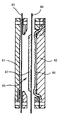
- Patent Document 1 a plurality of filter chambers 85 in which a pair of filter cloths 83 and 84 are arranged between the filter plates 81 and 82 are arranged in parallel, and the stock solution is press-fitted into each filter chamber 85. Later, a filter press dehydrator that expands the diaphragm 86 and squeezes the undiluted solution to separate the solid and liquid with the filter cloths 83 and 84, and then separates the filter plates 81 and 82 from each other to drop and discharge the dehydrated cake 87 is proposed. Has been.
- the dehydrated cake adheres to both the filter cloth on the filter plate side and the diaphragm side after the solid-liquid separation, and after the filter plate is separated, the dehydrated cake is removed from the filter cloth. If the residue of the dehydrated cake does not easily peel off and remains on the surface of the filter cloth, the filter cloth is clogged at an early stage and the filter cloth needs to be replaced frequently.
- a scraper is provided facing the surface of the filter cloth, and the dewatered cake attached to the filter cloth surface is peeled and dropped by moving the filter cloth.
- the dewatered cake adheres to either the filter plate side or the diaphragm side. Therefore, if neither the filter cloth on the filter plate side nor the diaphragm side is provided with a scraper, the dehydrated cake attached to the filter cloth surface cannot be peeled off. Further, in order to surely peel and drop the dehydrated cake, it is necessary to bring the scraper into contact with the surface of the filter cloth, which may damage and damage the filter cloth surface.
- the present invention provides a filter press dehydrator in which a dewatered cake can be attached only to either the filter cloth on the filter plate side or the diaphragm side, and the dewatered cake can be easily detached from the filter cloth. Objective.
- the filter press dehydrator according to the present invention is characterized in that a filter plate and a diaphragm are arranged to face each other via a pair of filter cloths as described in claim 1 of the claims.
- the dewatered cake tends to adhere to the filter cloth on the side where the drainage groove is formed so that the gap amount is increased, and the adhesion of the dehydrated cake to the other filter cloth is suppressed. be able to. Further, since such a dehydrated cake has a low water content at the contact portion with the filter cloth, the dehydrated cake can be easily detached without remaining on the filter cloth with a slight impact.
- the second characteristic configuration includes, in addition to the first characteristic configuration described above, an upper support portion in which the pair of filter cloths are provided above the filter chamber, and a lower portion. It is stretched in the vertical direction by the lower support part provided, each filter cloth is configured to be movable in the vertical direction in a state where the filter plate and the diaphragm are separated from each other, and a drainage groove formed between the filter plate and the diaphragm. The filter cloth on the side having a larger amount of voids moves downward and the other filter cloth moves upward.
- the third feature configuration is that, as described in claim 3, in addition to the second feature configuration described above, the filter cloth is configured to start moving at a predetermined acceleration from a stopped state.
- the predetermined acceleration means that the inertial force acting on the dewatered cake by the acceleration at the start of the movement of the filter cloth exceeds the force adhering to the filter cloth surface of the dehydrated cake, so that the contact surface between the dewatered cake and the filter cloth This is the acceleration above the minimum acceleration at which slipping and peeling can occur.
- the amount of voids in the drainage grooves formed in the diaphragm is reduced in the filter plate. It exists in the point set so that it may become more than the space
- the manufacturing cost can be reduced by making the gap amount of the drainage groove formed in the diaphragm larger than the gap amount of the drainage groove formed in the filter plate.
- a corrugated drainage groove is provided in the vertical direction on the surface of the filter plate. It is in the point formed in parallel with a plurality.
- the filter cloth is not easily caught in the drainage groove. Can prevent the breakage of the filter cloth.
- processing into a corrugated drainage groove can reduce the processing cost because the processing steps can be simplified compared to processing into a radial, mesh, or other complex shape.
- the dewatering cake can be attached only to the filter cloth on either the filter plate side or the diaphragm side, and the dewatering cake can be easily detached from the filter cloth.
- a dehydrator can be provided.
- FIG. 1 is a schematic view of a filter press dehydrator according to the present invention.
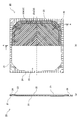
- 2A is an explanatory diagram of the diaphragm, which is a cross-sectional view taken along line AA of the front view, and FIG. 2B is a front view.
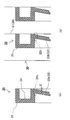
- FIG. 3A is a detailed view of the edge portion of the diaphragm, and FIG. 3B is an explanatory view of the thickness of the diaphragm and the thickness at the rising portion.
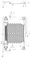
- 4A is a front view of the filter plate, and FIG. 4B is a side view of the filter plate.
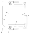
- FIG. 5A is a plan view of the filter plate, and FIG. 5B is a back view of the filter plate.
- FIG. 6A is a side sectional view showing a state where the diaphragm is fitted into the filter plate
- FIG. 6B is a plan view
- FIG. 6C is a back view
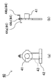
- FIG. 7A is a front view of the stock solution supply member
- FIG. 7B is a side view of the stock solution supply member
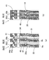
- FIG. 8A is a schematic diagram illustrating a state in which the filtration unit is opened
- FIG. 8B is a schematic diagram illustrating a state in which the filtration unit is closed.
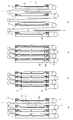
- 9A is an explanatory diagram of the closing plate process
- FIG. 9B is an explanatory diagram of the filtration process
- FIG. 9C is an explanatory diagram of the pressing process
- FIG. 9D is an opening plate / dehydrated cake discharging process.
- FIG. 10A is a front view of a diaphragm according to another embodiment
- FIG. 10B is a front view of a diaphragm according to another embodiment
- FIG. 11 is a front view of a filter plate according to another embodiment
- FIG. 12 is an explanatory view of a conventional filter press dehydrator.
- FIG. 13 is a cross-sectional view of a main part of a conventional filter press dehydrator.
- the filter press dehydrator 100 has a pair of guide rails 3 horizontally mounted between a left frame 1 and a right frame 2, and a large number of filtration units 4 are placed on the left frame 1 on the pair of guide rails 3. And the right frame 2 are slidably mounted.
- the right frame 2 is provided with a pressing cylinder 6, and a pressing member 5 is provided at the tip of the rod 6 a of the pressing cylinder 6.
- the plurality of filtration units 4 are connected to adjacent filtration units 4 by link members (not shown), the rightmost filtration unit 4 in FIG. 1 is connected to a filtration unit driving device, and the leftmost filtration unit 4 is a left frame 1. It is connected with the side.
- the filtration unit 4 sequentially moves in the right direction, and the filtration units 4 are separated by a link member at a predetermined interval.
- the movement of the filtration unit 4 is not limited to the above-described mode, and the filtration unit 4 is suspended on a chain (not shown) disposed between sprockets (not shown) provided in the left frame 1 and the right frame 2.
- the configuration may be such that the filtration unit 4 suspended on the chain is moved by driving the sprocket and moving the chain.
- an endless filter cloth 9 stretched between an upper roller 7 as a plurality of upper support portions and a lower roller 8 as a lower support portion is disposed in the vertical direction.
- the left frame 1 is provided with a stock solution supply port 15 for supplying a stock solution that is an object to be squeezed into the filter chamber 14 and a filtrate discharge port 16 for discharging the filtrate compressed in the filter chamber 14.
- the filtrate is discharged from the filtrate discharge port 16.
- the filtration unit 4 is opened by the filtration unit driving device, the dehydrated cake dehydrated from between the plurality of filtration units 4 is discharged.
- the filtration unit 4 is composed of a pair of diaphragms 20 and a filter plate 30.
- a thick part 21 that functions as a filter frame is integrally formed around a thin part 22 that squeezes the stock solution.
- the thick portion 21 of the diaphragm 20 functions as a sealing surface of the filter chamber 14 by being compressed by two adjacent filter plates. Therefore, there is no need to use a separate seal member, and the number of parts can be reduced.
- a plurality of rectangular filtrate drain grooves 25 having the same center as the center of the diaphragm 20 are formed on the flat surface 22a and the inclined surface 22b of the thin portion 22.
- the cross-sectional shape of the drainage groove 25 may be appropriately formed in a rectangular shape, a V shape, an arc shape, or the like in consideration of the expansion of the thin portion 22 of the diaphragm 20 in the pressing process of the dehydrated cake.
- the flat surface 22a The shape may be different between the inclined surface 22b.
- the pitch between the adjacent drain grooves 25 may be varied.
- the drainage groove 25 is formed by appropriately setting the shape, width, depth, total length, number, etc. of the groove.
- the void amount of the drainage groove 25 formed in the diaphragm 20 is formed to be larger than the void amount of the drainage groove formed in the filter plate.
- the void amount of the drainage groove means the amount of the drainage groove dug, that is, the amount obtained by integrating the voids formed for draining the filtrate, and the drainage groove shape, width, depth described above. The total length, number, etc. can be set.
- the edge of the thin portion 22 is connected to a position separated by a distance d from one end in the thickness direction of the inner periphery of the thick portion 21, and the central portion of the thin portion 22 is thick. It is formed on a flat surface 22a (see FIG. 2) projecting to the other end in the thickness direction of the portion 21, and the flat surface 22a and the edge portion are connected by an inclined surface 22b.
- a filtrate discharge passage 26 penetrating in the front-rear direction is formed in the left and right lower portions of the diaphragm 20 so that the filtrate flowing from the drainage groove 25 can be passed through.
- the diaphragm 20 is not particularly limited in material, but the thick portion 21 is subjected to a large pressure that functions as a sealing surface, and the thin portion 22 is moved to squeeze the stock solution. Those having flexibility are preferred.
- the diaphragm 20 can integrally form the thick portion 21 and the thin portion 22 by injection molding a polymer compound such as a thermoplastic elastomer.
- a polymer compound such as a thermoplastic elastomer.
- the thick portion 21 and the thin portion 22 the number of components necessary for forming a filter chamber such as a diaphragm installation frame can be reduced.
- the thick portion 21 is sandwiched by a pressure that can withstand the supply pressure of the stock solution supplied into the filter chamber and functions as a seal surface.
- the diaphragm 20 needs to maintain the function as a movable part that squeezes the stock solution while maintaining the function as a sealing surface, and therefore the hardness when using the elastomer resin is preferably in the range of about JIS A hardness 65 to 90. .
- the thick portion 21 may have a solid structure, or as shown in FIG. 2, a plurality of recesses 24 are formed so as to be alternately front and back, so that the thickness of each portion of the diaphragm 20 is different. By reducing the above, it may be formed so as to prevent a bias in shrinkage during cooling of injection molding.
- one side surface of the filter plate 30 is provided with a compression unit 31 that compresses the stock solution with the adjacent diaphragm 20, and the filtrate compressed in the filter chamber 14 is compressed in the compression unit 31.
- a plurality of sinusoidal drainage grooves 32a are formed in parallel in the longitudinal direction of water flow, and each drainage groove 32a is connected by a lower connection groove 32b.
- the connecting groove 32 b is formed to be inclined downward from the center of the filter plate 30 to the left and right sides, and is configured to communicate with a filtrate discharge passage 33 formed at the lower left and right of the filter plate 30.
- the cross-sectional shape of the drainage groove 32a may be formed in a rectangular shape, a V shape, an arc shape, or the like, and the pitch with the adjacent drainage groove 32a may be varied.
- the drainage groove 32a is formed so as to reduce the amount of voids by appropriately setting the shape, width, depth, total length, number, etc. of the groove, compared to the drainage groove 25 formed in the diaphragm 20. Has been.
- the drainage groove 25 of the filtrate formed in the diaphragm 20 has a larger amount of voids than the drainage groove 32a of the filtrate formed in the filter plate 30, when the dewatered cake is squeezed in the filter chamber 14, the drainage groove 25 In this case, the amount of filtrate flowing is greater than in the drainage groove 32a. Therefore, the dehydrated cake has a lower moisture content on the diaphragm 20 side than on the filter plate 30 side, increases the contact area, and adheres to the filter cloth 9 on the diaphragm 20 side.
- a filtrate discharge passage 34 is formed below the filtrate discharge passage 33 so as to communicate with the filtrate discharge passage 26 in a state where the diaphragm 20 is fitted in the filter plate 30.
- a stock solution supply passage 35 penetrating in the front-rear direction is provided at the upper left and right sides of the filter plate 30, and a recess 36 into which the stock solution supply member 40 can be loosely inserted is formed at the periphery of the stock solution supply passage 35. 36a is provided.
- a pair of slide pieces 45 for mounting on the pair of guide rails 3 are attached to the left and right sides of the filter plate 30.
- a rising portion 37 and a mounting surface 38 into which the diaphragm 20 can be fitted are formed on the other side of the back surface of the compression portion 31 of the filter plate 30.
- the thickness of the rising portion 37 is set to be smaller than the thickness of the diaphragm 20.
- the thickness of the thick portion 21 of the diaphragm 20 is larger than the thickness of the rising portion 37, so that the difference in thickness is a compression allowance between adjacent filter plates. It becomes.
- the pressing force applied by the pressing cylinder 6 is large enough to prevent the stock solution in the filter chamber 14 from leaking out.
- the pressing force by the pressing cylinder 6 is stronger than a predetermined pressure required for sealing the diaphragm 20.
- the rising portion 37 supports pressure with the adjacent filter plate 30, so that the thick portion 21 of the diaphragm 20 Since a pressure higher than a predetermined pressure is not applied, it is possible to avoid the possibility of deformation or breakage due to excessive tightening of the thick portion 21, so that the sealing effect of the sealing surface can be stabilized.
- the left and right rising portions 37 are compressed at a predetermined pressure. It is configured to be.
- the diaphragm 20 is fixed to the mounting surface 38 with bolts or the like as appropriate.
- a pressurized water inlet 39 a and a pressurized water inlet path 39 b for supplying pressurized water for inflating the diaphragm 20 toward the compression portion 31 side of the adjacent filter plate are formed.
- the pressurized water is introduced from the pressurized water supply pipe 46 attached to the lower portion of the filter plate 30. It is supplied between the attachment surface 38 and the back surface 23 of the thin portion of the diaphragm 20 through the passage 39b and the pressurized water inlet 39a, and the thin portion 22 of the diaphragm 20 expands toward the compression portion 31 side of the adjacent filter plate 30. It will be.
- the filter plate 30 is made by extruding a synthetic resin material such as polypropylene, for example, the conventional metal filter plate is used in terms of strength while taking advantage of the lightness and chemical resistance that are the characteristics of the compatible resin. Is not inferior to The filter plate 30 becomes lighter, the weight of the plurality of filtration units 4 arranged in parallel is reduced, and the filter press dehydrator 100 can be enlarged.
- the stock solution supply member 40 includes a stock solution supply pipe 41 that can be inserted into the stock solution supply path 35 and a stock solution supply section 42 that is loosely inserted into the recess 34 of the filter plate 30.
- the stock solution supply section 42 is formed with a stock solution supply path 43 that branches perpendicularly from the stock solution supply pipe 41 and supplies the stock solution supplied from the stock solution supply pipe 41 into the filter chamber 14.
- the stock solution supply member 40 is positioned so that the stock solution supply member 40 is positioned at a predetermined position with the filter plate 30 into which the stock solution supply member 40 is loosely inserted and the adjacent filter plate being opened.
- Link members 44a and 44b are attached by bolts 44c.
- the stock solution supply part 42 of the stock solution supply member 40 is supported by the filter plate 30a.
- the stock solution is placed in the filter chamber 14 formed between the thin wall portion 22 of the diaphragm 20a and the compression portion 31 of the filter plate 30b. Will be supplied.
- the stock solution supply member 40 is loosely inserted into the recess 34 of the filter plate 30 when the adjacent filtration units 4 a and 4 b are pressed to form the filter chamber 14 between the pair of filter cloths 9.
- the stock solution supply pipe 41 is accommodated in the stock solution supply path 35 and is configured to be connected to the stock solution supply path 35 of the adjacent filtration unit 4.
- the stock solution is supplied from the stock solution supply port 15 to the stock solution supply path 35, the stock solution is supplied to each filter chamber 14 via the stock solution supply member 40.
- the filter cloth 9 is formed in an endless shape, and is a pair of filters that are folded back by an upper roller 7 provided above the filter chamber 14 and a lower roller 8 provided below and stretched in the vertical direction.
- the fabrics 9a and 9b are sandwiched between adjacent filter plates 30.
- a guide roller 18 for guiding the filter cloth 9 so as not to contact the filter plate 30 and the diaphragm 20 is provided in the vicinity of each upper roller 7, and the filter cloth 9 is provided with a filter cloth tension provided in the upper frame 17.
- the apparatus 10 is configured so as not to bend by being tensioned.
- the arrangement of the rollers is not limited to the above-described one, and can be set as appropriate.
- the upper frame 17 is provided with a filter cloth meandering prevention device 11 for preventing the filter cloth 9 from meandering and a filter cloth driving device 12 for driving the filter cloth 9.
- the filter cloth driving device 12 is configured such that the filter cloth 9a on the diaphragm 20 side moves downward when the filter cloth 9 is driven with the filter plate 30 and the diaphragm 20 constituting the filter chamber 14 open. Therefore, even if the diaphragm 20 and the filter plate 30 constituting the filter chamber 14 are opened in the opening plate / dehydrated cake discharging step, even if the dehydrated cake 19 is not fixed and dropped on the filter cloth 9a on the diaphragm 20 side, the filter cloth 9a. Is moved downward, the dewatered cake attached to the surface of the filter cloth 9a can be peeled and dropped.
- the filter cloth driving device 12 is configured to start moving the filter cloth 9 at a predetermined acceleration from a stopped state.
- the predetermined acceleration means that the inertial force acting on the dewatered cake by the acceleration at the start of the movement of the filter cloth exceeds the force adhering to the filter cloth surface of the dehydrated cake, so that the contact surface between the dewatered cake and the filter cloth This is the acceleration above the minimum acceleration at which slipping and peeling can occur.
- the filter cloth 9 is accelerated rapidly and starts moving, the dehydrated cake attached to the surface of the filter cloth 9 is peeled and dropped.
- the dewatered cake 19 is reliably peeled off when the filter cloth 9a is folded back by the lower roller 8, and can be removed by dropping.
- the cleaning device 13 provided in the upper frame 17 sprays the cleaning liquid supplied from the outside even when the residue of the dewatered cake remains on the surface of the filter cloth 9 or when the filter cloth 9 is clogged. And can be cleaned. In this way, since the entire surface can be cleaned by circulating the filter cloth 9, it is not necessary for the operator to clean the filter cloth 9 for each filtration unit.
- the filter cloth 9 is circulated by the filter cloth driving device 12, whereby the entire surface can be used efficiently.
- the filter cloth 9 may not be configured to be circulated by the filter cloth driving device 14 using a single endless filter cloth 9.
- a configuration in which a pair of filter cloths are stretched between the plurality of filtration units 4 and the pair of filter cloths between the filtration units 4 respectively move downward is also possible.
- the filter press dehydrator 100 configured as described above is operated in the order of a closing plate process, a filtration process, a pressing process, and an open plate / dehydrated cake discharging process.
- the pressing member 5 is advanced through the rod 6 a of the pressing cylinder 6 to press the plurality of filter plate units 4, and a plurality of portions are interposed between the thin portion 22 of the diaphragm 20 and the compression portion 31 of the filter plate 30. This is a step of forming a filter chamber.
- the pressure cylinder 6 is operated with the filter cloth 9 disposed between the adjacent filtration units 4 to advance the pressure member 5 through the rod 6a, and the filtration unit 4 is moved to the left.
- a plurality of filter chambers 14 are formed between the filter cloths 9 by pressing in the frame 1 direction.
- the filtration process is a process in which the stock solution is pressed into the pair of filter cloths 9 of the filter chamber 14 formed by the closed plate process and filtered.
- the stock solution is press-fitted into the filter chamber 14 formed by the closing plate process from the stock solution supply port 15 on the left frame 1 side, and is filtered with a filter cloth 9.
- the filtrate flowing from the drainage grooves 25 and the drainage grooves 32 a is drained from the filtrate discharge port 16 to the outside of the filter press dehydrator 100.
- the squeezing step is a step of compressing and dehydrating the residue containing moisture remaining between the filter cloths 9 in the filtration step to form a dehydrated cake.
- pressurized water is supplied from the pressurized water supply pipe 46 to the back surface 23 of the thin wall portion of the diaphragm 20 through the pressurized water introduction path 39b and the pressurized water introduction port 39a, and the diaphragm 20 is connected to the adjacent filter plate 30.
- the dewatered cake 19 swelled to the compression unit 31 side and remains between the filter cloths 9 is pressed to the compression unit 31 side of the other filter plate 30 to perform compression dehydration.
- the dehydrated cake 19 is no longer compressed, and the diaphragm 20 cannot expand, so that the pressurized water does not flow.
- the plate opening and dewatering cake discharging step is a step of stopping the supply of pressurized water and contracting the diaphragm 20, then retracting the rod 6 a of the pressing cylinder 6, opening each filtration unit 4, and discharging the dewatering cake 19. .
- the filter cloth 9 is folded back by the lower roller 8 at the lower end of the diaphragm 20, and the dewatered cake 19 attached to the surface of the filter cloth is completely peeled and dropped and removed.
- the configuration in which the drainage groove 25 is formed on the flat surface 22a and the inclined surface 22b of the thin portion 22 of the diaphragm 20 has been described, but the shape of the drainage groove is not limited thereto.
- the drainage groove 50 may be formed only on the flat surface 22a of the thin portion 22. Furthermore, instead of the plurality of recesses 24 formed in the thick part 21, a plurality of endless recesses 51 may be alternately formed on the front and back sides.
- the shape of the drainage groove is a combination of a linear drainage groove 52 extending radially from the center of the diaphragm 20 and a concentric drainage groove 53 with respect to the radial direction of the diaphragm 20. It may be a shape. In any case, the drainage groove is symmetrical with respect to the center of the diaphragm 20 and is concentric with the radial direction of the diaphragm 20 so that the void amount is larger than that of the filtrate drainage groove formed on the filter plate. It only has to be configured.
- a configuration in which a plurality of triangular drainage grooves 54 are formed in parallel in the vertical direction may be used, or a sawtooth wave type or a rectangular wave type may be used.
- the filter cloth has a shape that does not easily get caught in the drainage groove, and the gap amount is smaller than that of the drainage groove formed in the diaphragm.
- the drainage groove in which the diaphragm is formed has a larger amount of voids than the drainage groove formed in the filter plate.
- the diaphragm is obtained by injection molding a polymer compound such as a thermoplastic elastomer, so the drain plate can be made once regardless of the shape of the drainage groove, whereas the filter plate is made of polypropylene. Since a drainage groove may be cut into a product obtained by extrusion molding such a synthetic resin material, if there are many cutting amounts and cutting steps, the processing cost will increase.
- the drainage groove of the filter plate is configured such that the gap amount is smaller than the drainage groove of the diaphragm.
- the drainage groove formed in the diaphragm may be configured so that the gap amount of the drainage groove formed in the filter plate is reduced, and the filter cloth on the filter plate side may be moved downward.
- the configuration is not limited to the case where all the diaphragms or one of the filter plates has a large amount of gaps.
Landscapes
- Chemical & Material Sciences (AREA)
- Chemical Kinetics & Catalysis (AREA)
- Filtration Of Liquid (AREA)
Abstract
ろ板側またはダイヤフラム側の何れか一方のろ布のみに脱水ケーキが付着させることができ、ろ布から脱水ケーキを容易に離脱させることができるフィルタプレス脱水機を提供する。 ダイヤフラム20に形成された排水溝25の空隙量がろ板30に形成された排水溝32aの空隙量より多くなるように構成し、ろ板20及びダイヤフラム20が離隔した状態で上下何れかの方向に移動可能なろ布9a,9bのうち、ダイヤフラム20側のろ布9aが下方に移動し、他方のろ布9bが上方に移動するように構成する。よって、ダイヤフラム20側のろ布9aに対してケーキ19が付着し易く、他方のろ布9bへのケーキ19の付着を抑制することができ、ケーキ19が付着した側のろ布9aを下方向に移動させると、ろ布9aが下部ローラ8により折り返され、ケーキ19を容易に離脱落下できる。
Description
本発明は、ろ板とダイヤフラムが一対のろ布を介して対向配置され、前記一対のろ布の間に形成されるろ室に原液を供給して圧搾するフィルタプレス脱水機に関する。
従来、洗水場、し尿処理場、都市下水処理場、産業排水処理場等で発生する各種汚泥の処理工程や生産設備でのカーボン製品、チタン製品等の各種製造工程における固液分離用脱水機としてフィルタプレス脱水機が広く用いられている。
図13に示すように、特許文献1には、ろ板81,82間に一対のろ布83,84が配置された複数のろ室85を並設し、各ろ室85に原液を圧入した後に、ダイヤフラム86を膨張させて原液を圧搾することによりろ布83,84で固液分離し、その後、ろ板81,82を互いに離隔させて脱水ケーキ87を落下排出するフィルタプレス脱水機が提案されている。
しかし、上述のような従来のフィルタプレス脱水機では、固液分離後にろ板側及びダイヤフラム側の双方のろ布に脱水ケーキが付着して、ろ板を離隔した後に、脱水ケーキがろ布から容易に剥離落下せず、脱水ケーキの残滓がろ布の表面に残留すると、ろ布が早期に目詰まりし、ろ布の交換作業が頻発するという問題があった。
このような、ろ布の目詰まりを解消するためには、ろ布を振動させる振動機構を備え、振動によりろ布から脱水ケーキを落下させることが考えられるが、振動機構を備えるためにフィルタプレス脱水機の製作コストが高くなる。
また、ろ布に付着した脱水ケーキを作業員が手作業で剥離落下させることが考えられるが、非常に煩雑である。
そこで、スクレイパーをろ布表面に対向させて備え、ろ布を移動させることでろ布表面に付着した脱水ケーキを剥離落下させることが考えられるが、脱水ケーキがろ板側またはダイヤフラム側のどちらに付着するか分からないため、ろ板側及びダイヤフラム側のどちらのろ布にもスクレイパーを備えなければ、ろ布表面に付着した脱水ケーキを剥離落下させることができない。また、脱水ケーキを確実に剥離落下させるめには、スクレイパーをろ布表面に当接させる必要があり、ろ布表面を傷つけ破損させる虞もあった。
本発明は、ろ板側またはダイヤフラム側の何れか一方のろ布のみに脱水ケーキが付着させることができ、ろ布から脱水ケーキを容易に離脱させることができるフィルタプレス脱水機を提供することを目的とする。
上述の目的を達成するため、本発明によるフィルタプレス脱水機の特徴構成は、特許請求の範囲の書類の請求項1に記載した通り、ろ板とダイヤフラムが一対のろ布を介して対向配置され、前記一対のろ布の間に形成されるろ室に原液を供給して圧搾するフィルタプレス脱水機であって、前記ろ板に形成されたろ液の排水溝と、前記ダイヤフラムに形成されたろ液の排水溝のうち、何れか一方が他方よりも空隙量が多くなるように構成されている点にある。
ろ室で原液が圧搾される際に、ろ液が排出されるにつれて脱水ケーキの含水率が低下して固まる。このとき、ろ板に形成されたろ液の排水溝と、ダイヤフラムに形成されたろ液の排水溝のうち、空隙量が多い側の排水溝から多量のろ液が流れ、ろ板側とダイヤフラム側とで脱水ケーキの含水率に差が生じて、含水率が低い側のろ布への接触面積が増大する。
その結果、ろ板とダイヤフラムのうち、空隙量が多くなるように排水溝が形成された側のろ布に対して脱水ケーキが付着し易く、他方のろ布への脱水ケーキの付着を抑制することができる。さらに、そのような脱水ケーキはろ布との接触部で含水率が低くなっているため、僅かの衝撃で脱水ケーキがろ布に残留することなく容易に離脱させることができるようになる。
同第二の特徴構成は、同請求項2に記載した通り、上述の第一の特徴構成に加えて、前記一対のろ布が前記ろ室の上方に備えられた上部支持部と、下方に備えられた下部支持部により上下方向に張設され、前記ろ板及びダイヤフラムが離隔した状態で各ろ布が上下方向に移動可能に構成され、前記ろ板とダイヤフラムのうち形成された排水溝の空隙量が多い側のろ布が下方に移動し、他方のろ布が上方に移動するように構成されている点にある。
一方のろ布が下方に移動し他方のろ布が上方に移動することにより、脱水ケーキの両面に作用する互いに異なる方向への力が、ろ布から脱水ケーキを剥離するための剥離力となる。このとき、含水率が低い側のろ布よりも含水率が高い側のろ布から脱水ケーキが剥離し易く、含水率が低い側のろ布に脱水ケーキが付着する場合であっても、当該脱水ケーキが付着した側のろ布を下方向に移動させる際に、脱水ケーキが下方に付勢され、容易に離脱落下するようになる。
同第三の特徴構成は、同請求項3に記載した通り、上述の第二特徴構成に加えて、ろ布は、停止状態から所定加速度で移動開始するように構成されている点にある。
上述の構成によれば、ろ布が所定加速度で移動開始するため、ろ布の表面に付着した脱水ケーキが剥離落下しやすくなる。ここで、所定加速度とは、ろ布の移動開始時の加速により脱水ケーキに働く慣性力が、脱水ケーキのろ布表面に対して付着する力を上回ることにより、脱水ケーキとろ布の接触面にすべりが生じ、剥離が起こるり得る最低の加速度以上の加速度をいう。
同第四の特徴構成は、同請求項4に記載した通り、上述の第一から第三の何れかの特徴構成に加えて、前記ダイヤフラムに形成された排水溝の空隙量が前記ろ板に形成された排水溝の空隙量より多くなるように設定されている点にある。
ダイヤフラムを、例えば高分子化合物を射出成形することにより得る場合、排水溝がどのような形状であっても一度金型を作れば済むのに対し、ろ板を合成樹脂材を押出成形することによって得る場合、排水溝を切削加工する必要があるため、切削量、切削工程が多いと、加工費が上がる。よって、ダイヤフラムに形成された排水溝の空隙量がろ板に形成された排水溝の空隙量より多くなるようにする方が、製作コストが低減できる。
同第五の特徴構成は、同請求項5に記載した通り、上述の第一から第四の何れかの特徴構成に加えて、前記ろ板の表面に、縦方向に波型の排水溝が複数本並列に形成されている点にある。
上述の構成によれば、縦方向に排水溝を形成することで、ろ液は上から下方向にスムーズに流れ、さらに排水溝を波型に形成することで、ろ布が排水溝に挟まりにくくすることができ、ろ布の破損を防止できる。なお、波型の排水溝に加工することは、放射状や網目状その他複雑な形状に加工する場合に比べて、加工工程を簡略化できるため加工費を低減できる。
以上説明した通り、本発明によれば、ろ板側またはダイヤフラム側の何れか一方のろ布のみに脱水ケーキが付着させることができ、ろ布から脱水ケーキを容易に離脱させることができるフィルタプレス脱水機を提供することができるようになった。
以下に本発明によるフィルタプレス脱水機を説明する。
図1に示すように、フィルタプレス脱水機100は、左フレーム1、右フレーム2間に一対のガイドレール3が横架してあり、一対のガイドレール3に多数のろ過ユニット4が左フレーム1と右フレーム2との間で摺動可能に載架されている。右フレーム2には押圧シリンダ6が設けられ、押圧シリンダ6のロッド6aの先端には押圧部材5が備えられている。
複数のろ過ユニット4はそれぞれ隣接するろ過ユニット4とリンク部材(図示せず)で連結され、図1中右端のろ過ユニット4はろ過ユニット駆動装置と連結され、左端のろ過ユニット4は左フレーム1側と連結されている。右端のろ過ユニット4が右方向に移動すると、それにつられて順次ろ過ユニット4が右方向に移動し、リンク部材によってそれぞれのろ過ユニット4が所定間隔で離間するように構成されている。
なお、ろ過ユニット4の移動は上述の態様に限らず、左フレーム1と右フレーム2に備えたスプロケット(図示せず)間に配設したチェーン(図示せず)にろ過ユニット4を懸架して、スプロケットを駆動しチェーンを移動させることで、当該チェーンに懸架されたろ過ユニット4を移動させる構成であってもよい。
隣接するろ過ユニット4間には、複数の上部支持部としての上部ローラ7と下部支持部としての下部ローラ8の間に張設された無端状のろ布9が上下方向に配設されている。
押圧部材5を介して押圧シリンダ6によって複数のろ過ユニット4がそれぞれの間にろ布9を挟んだ状態で、右フレーム2方向から左フレーム1方向に所定圧力で押圧されて閉板され、ろ布9に囲まれた複数のろ室14が形成されるように構成されている。
左フレーム1には、ろ室14内に圧搾対象物である原液を供給する原液供給口15と、ろ室14で圧搾されたろ液が排出されるろ液排出口16が備えられている。
原液供給口15から、原液をろ室14内に供給し、ろ過ユニット4で圧搾すると、ろ液はろ液排出口16から排出される。ろ過ユニット駆動装置でろ過ユニット4を開板すると、複数のろ過ユニット4間から脱水された脱水ケーキが排出される。
以下、上述の各構成について詳述する。
ろ過ユニット4は、一対のダイヤフラム20とろ板30とで構成されている。図2(a),(b)に示すように、ダイヤフラム20は、ろ枠として機能する厚肉部21が、原液を圧搾する薄肉部22の周囲に一体に成形されている。ダイヤフラム20の厚肉部21は、隣接する二枚のろ板で圧縮されることによりろ室14のシール面として機能する。よって、別にシール部材を用いる必要がないので、部品点数を減らすことができる。
ろ過ユニット4は、一対のダイヤフラム20とろ板30とで構成されている。図2(a),(b)に示すように、ダイヤフラム20は、ろ枠として機能する厚肉部21が、原液を圧搾する薄肉部22の周囲に一体に成形されている。ダイヤフラム20の厚肉部21は、隣接する二枚のろ板で圧縮されることによりろ室14のシール面として機能する。よって、別にシール部材を用いる必要がないので、部品点数を減らすことができる。
図2(b)に示すように、薄肉部22の平坦面22a及び傾斜面22bには、ダイヤフラム20の中心と中心を同じくする矩形のろ液の排水溝25が複数形成されている。
排水溝25の断面形状は、ダイヤフラム20の薄肉部22は、脱水ケーキの圧搾工程で膨張することを考慮し、適宜矩形状、V字状、円弧状等に形成すればよく、例えば平坦面22aと傾斜面22bで形状を異ならせてもよい。さらに隣接する排水溝25とのピッチを異ならせてもよい。
排水溝25は、溝の形状、幅、深さ、累計長さ、数等を適宜設定して形成される。
本実施形態では、ダイヤフラム20に形成した排水溝25の空隙量が、ろ板に形成した排水溝の空隙量よりも多くなるように形成されている。なお、排水溝の空隙量とは、排水溝が掘り込まれた量、すなわち、ろ液が排水されるために形成された空隙を積算した量をいい、上述した排水溝の形状、幅、深さ、累計長さ、数等によって設定することができる。
図3(a)に示すように、薄肉部22の縁部は、厚肉部21の内周の厚み方向一端部から距離d離隔した位置に連接され、薄肉部22の中央部は、厚肉部21の厚み方向他端部側に張り出した平坦面22a(図2参照)に形成され、平坦面22aと縁部とが傾斜面22bで連接されている。
図3(b)に示すように、ろ室内の原液を圧搾するために薄肉部22を可動させると、薄肉部22の縁部22cには繰り返し応力がかかるが、縁部22cを厚肉部21の内周の厚み方向一端部から距離d離隔した位置に連接することで、応力集中が大きい縁部22cとろ板30の圧縮部31との接触による摩擦を回避できるので、破損の虞を低減し寿命を延ばすことができる。
図2に戻り、ダイヤフラム20の左右下部には、前後方向に貫通したろ液排出通路26が形成され、排水溝25から流れてくるろ液を通水できるように構成されている。
このようなダイヤフラム20は、材質は特に問わないが、厚肉部21にはシール面として機能する程度の大きな圧力がかかり、薄肉部22は原液を圧搾するために可動するので、適度な硬さと柔軟さを併せ持つものが好ましい。
例えば、ダイヤフラム20は、熱可塑性エラストマのような高分子化合物を射出成形により厚肉部21及び薄肉部22を一体成形することができる。厚肉部21及び薄肉部22を一体成形することで、ダイヤフラムの設置枠のようなろ室の形成に必要な構成品数を減らすことができる。なお、厚肉部21は、ろ室内に供給される原液の供給圧力に耐え、シール面として機能する程度の圧力で挟まれる。
ダイヤフラム20は、シール面としての機能を保ちつつ、原液を圧搾する可動部としての機能を保つ必要があるため、エラストマ樹脂を使用する場合の硬度は、JIS A硬度65~90程度の範囲が好ましい。
厚肉部21は、中実構造であってもよいし、図2に示すように、表裏互い違いになるように複数の凹部24を形成して肉をぬすみ、ダイヤフラム20の各部の厚さの差を減らすことで、射出成形の冷却時の縮みの偏りを防止するように形成してもよい。
図4(a)に示すように、ろ板30の一側面には、隣接するダイヤフラム20との間で原液を圧縮する圧縮部31を備え、圧縮部31にろ室14で圧搾されたろ液を通水する縦方向に正弦波型の排水溝32aが複数本並列して形成され、それぞれの排水溝32aは下部の連結溝32bで連結されている。連結溝32bはろ板30の中央から左右側方にかけて下方へ傾斜して形成され、ろ板30の左右下方に形成されたろ液排出通路33に連通するように構成されている。
排水溝32aの断面形状は、矩形状、V字状、円弧状等に形成すればよく、隣接する排水溝32aとのピッチを異ならせてもよい。
本実施形態では、排水溝32aは、ダイヤフラム20に形成された排水溝25よりも、溝の形状、幅、深さ、累計長さ、数等を適宜設定して空隙量が少なくなるように形成されている。
ダイヤフラム20に形成されたろ液の排水溝25の方が、ろ板30に形成されたろ液の排水溝32aよりも空隙量が多いため、ろ室14で脱水ケーキを圧搾する際に、排水溝25の方が排水溝32aよりろ液の流れる量が多くなる。よって、脱水ケーキはろ板30側よりダイヤフラム20側の含水率が少なくなって接触面積が増大し、ダイヤフラム20側のろ布9に付着することとなる。
さらに、ろ液排出通路33の下方には、ダイヤフラム20をろ板30に嵌入した状態でろ液排出通路26と連通するようにろ液排出通路34が形成されている。
ろ板30の左右上方には、前後に貫通する原液供給路35が設けてあり、原液供給路35の周縁部に原液供給部材40が緩挿可能な凹部36が形成され、凹部36にはパッキン36aが備えられている。
ろ板30の左右側方には、一対のガイドレール3に載架するための一対のスライドピース45が取り付けられている。
図5(a),(b)に示すように、ろ板30の圧縮部31の裏面の他側面にはダイヤフラム20を嵌入可能な立上り部37及び取付面38が形成されている。立上り部37の厚さは、ダイヤフラム20の厚さよりも小さく設定されている。
つまり、ろ板30にダイヤフラム20を嵌入支持した際に、ダイヤフラム20の厚肉部21の厚さは、立上り部37の厚さより大きいため、この厚さの差が隣接するろ板との圧縮代となる。
通常、押圧シリンダ6により加えられる押圧力は、ろ室14内の原液が漏れださないような大きさであるが、押圧シリンダ6による押圧力がダイヤフラム20のシールに必要な所定圧力以上に強い場合でも、ダイヤフラム20の厚肉部21はろ板30の立上り部37と面一になった時点で、立上り部37が隣接するろ板30と圧力を支持するので、ダイヤフラム20の厚肉部21には所定圧以上の圧力がかからないので、厚肉部21の締め付けすぎによる変形や破損の虞を回避できるので、シール面のシール効果を安定させることができる。
左右の立上り部37は、取付面38にダイヤフラム20を嵌入支持した状態で、当該取付面38と隣接するろ板30の圧縮部31でダイヤフラム20を圧縮した際に、ダイヤフラム20が所定圧で圧縮されるように構成されている。なお、ダイヤフラム20は、取付面38に適宜ボルト等で固定される。
ろ板30の取付面38の中央下方には、ダイヤフラム20を隣接するろ板の圧縮部31側へと膨らませるための加圧水を供給する加圧水導入口39a及び加圧水導入路39bが形成されている。
図6(a),(b),(c)に示すように、ろ板30にダイヤフラム20を嵌入した際には、加圧水は、ろ板30の下部に取り付けられた加圧水供給管46から加圧水導入路39b、加圧水導入口39aを介して、取付面38とダイヤフラム20の薄肉部の裏面23の間に供給され、ダイヤフラム20の薄肉部22が隣接するろ板30の圧縮部31側へと膨張することとなる。
なお、ダイヤフラム20の薄肉部22を隣接するろ板30の圧縮部31側へと膨張させるのは、加圧水に限らず流体であればよく、例えば、加圧気体であってもよい。
ろ板30は、例えばポリプロピレンのような合成樹脂材を押出成形することで作成すれば、合性樹脂の特性である軽量性と耐薬品性を生かしながら、強度的にも従来の金属性ろ板に劣ることがない。ろ板30が軽量となり、並列する複数のろ過ユニット4の重量が軽減され、フィルタプレス脱水機100の大型化が可能となる。
図7(a),(b)に示すように、原液供給部材40は原液供給路35に挿通可能な原液供給管41と、ろ板30の凹部34に緩挿される原液供給部42で構成される。原液供給部42には原液供給管41から直交して分岐し、原液供給管41から供給される原液をろ室14内へと供給する原液給液路43が形成してある。
原液供給部材40には、当該原液供給部材40が緩挿されるろ板30と、隣接するろ板とが開いた状態で、原液供給部材40が所定の位置に配置されるように位置決めをする一対のリンク部材44a,44bがボルト44cにより取り付けられている。
図8(a),(b)に示すように、隣接したろ過ユニット4a,4bによる一対のろ布9の締め付けの際には、原液供給部材40の原液供給部42がろ板30aに支持されたダイヤフラム20とろ板30bの間に位置する一対のろ布9a,9bの間に挟まれる格好となり、ダイヤフラム20aの薄肉部22とろ板30bの圧縮部31の間に形成されたろ室14内に原液を供給することになる。
原液供給部材40は、隣接したろ過ユニット4a,4bを押圧し一対のろ布9間にろ室14を形成した際には、ろ板30の凹部34に緩挿される。原液供給管41は、原液供給路35内に収容され、隣接するろ過ユニット4の原液供給路35と連なるように構成されている。
原液供給口15から原液供給路35に原液を供給すると、原液供給部材40を介して各ろ室14に原液が供給される。
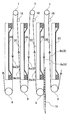
図9に示すように、ろ布9は無端状に形成され、ろ室14の上方に備えられた上部ローラ7と、下方に備えられた下部ローラ8により折り返され上下方向に張設されたろ一対の布9a,9bが、それぞれ隣接するろ板30の間に挟まれるように構成されている。なお、それぞれの上部ローラ7の近傍には、ろ布9がろ板30及びダイヤフラム20に接触しないように案内する案内ローラ18が備えられ、ろ布9は上フレーム17内に備えられたろ布緊張装置10により張力を与えられ撓まないように構成されている。なお、各ローラの配置は、上述のものに限らず適宜設定することが可能である。
さらに、上フレーム17には、ろ布9の蛇行を防止するろ布蛇行防止装置11、ろ布9を駆動するろ布駆動装置12が備えられている。
ろ布駆動装置12は、ろ室14を構成するろ板30及びダイヤフラム20が開いた状態でろ布9を駆動する際に、ダイヤフラム20側のろ布9aが下方向に動くように構成されているので、開板・脱水ケーキ排出工程で、ろ室14を構成するダイヤフラム20とろ板30を開板しても、ダイヤフラム20側のろ布9aに脱水ケーキ19が固着して落下しない場合でも、ろ布9aを下方に動かすことで、ろ布9aの表面に付着した脱水ケーキを剥離落下させることができる。
この際、ろ布駆動装置12は、ろ布9を停止状態から所定加速度で、移動開始するように構成されている。ここで、所定加速度とは、ろ布の移動開始時の加速により脱水ケーキに働く慣性力が、脱水ケーキのろ布表面に対して付着する力を上回ることにより、脱水ケーキとろ布の接触面にすべりが生じ、剥離が起こるり得る最低の加速度以上の加速度をいう。このように、ろ布9を急激に加速して移動開始するため、ろ布9の表面に付着した脱水ケーキが剥離落下するのである。
脱水ケーキがろ布9aの表面から完全に剥離しない場合であっても、ろ布9aが下部ローラ8により折り返される際に脱水ケーキ19が確実に剥離し、落下除去できる。
また、上フレーム17内に備えられた洗浄装置13により、脱水ケーキの残滓がろ布9の表面に残留したときや、ろ布9が目詰まりしたときでも、外部から供給される洗浄液を噴射して洗浄できるように構成されている。このように、ろ布9を循環させることで全面を洗浄できるため、作業員がろ過ユニットごとにろ布9を洗浄する必要がなくなる。
このように、一枚のろ布9で複数のろ室14を覆えば、ろ布駆動装置12によってろ布9を循環させることで、全面を効率よく使用できる。なお、ろ布9は、無端状の一枚のろ布9を用いて、ろ布駆動装置14によって循環させる構成でなくてもよい。複数のろ過ユニット4間にそれぞれ一対のろ布を張設して備え、各ろ過ユニット4間の一対のろ布がそれぞれ下方に移動するような構成であってもよい。
以上のように構成されたフィルタプレス脱水機100は、閉板工程、ろ過工程、圧搾工程、開板・脱水ケーキ排出工程の順序で運転される。
閉板工程は、押圧シリンダ6のロッド6aを介して押圧部材5を前進させて複数のろ板ユニット4を押圧し、ダイヤフラム20の薄肉部22及びろ板30の圧縮部31の間に複数のろ室を形成する工程である。
図10(a)に示すように、隣接するろ過ユニット4間にろ布9が配置された状態で押圧シリンダ6を作動させてロッド6aを介して押圧部材5を前進させ、ろ過ユニット4を左フレーム1方向に押圧してろ布9間に複数のろ室14を形成する。
ろ過工程は、閉板工程によって形成されたろ室14の一対のろ布9内に原液を圧入してろ過する工程である。
図10(b)に示すように、閉板工程によって形成されたろ室14に左フレーム1側の原液供給口15から原液を圧入してろ布9でろ過する。排水溝25及び排水溝32aから流れるろ液は、ろ液排出口16からフィルタプレス脱水機100の外部に排水される。
圧搾工程は、ろ過工程によってろ布9間に残った水分を含んだ残存物を圧縮して脱水し、脱水ケーキ状にする工程である。
図10(c)に示すように、加圧水供給管46から加圧水導入路39b、加圧水導入口39aを介してダイヤフラム20の薄肉部の裏面23に加圧水を供給し、ダイヤフラム20を隣接するろ板30の圧縮部31側へ膨らませて、ろ布9間に残留した脱水ケーキ19を他方のろ板30の圧縮部31側へ押圧して圧縮脱水する。
なお、脱水ケーキ19の圧縮脱水が十分になされたら、脱水ケーキ19はそれ以上圧縮されなくなり、ダイヤフラム20は膨らむことができなくなるので、加圧水は流入しなくなる。
開板、脱水ケーキ排出工程は、加圧水の供給を停止し、ダイヤフラム20を収縮させた後、押圧シリンダ6のロッド6aを後退させて、各ろ過ユニット4を開き、脱水ケーキ19を排出する工程である。
図10(d)に示すように、各ろ過ユニット4を開板すると、脱水ケーキ19はその自重でろ布9から落下する。脱水ケーキ19が自重で落下しない場合は、ダイヤフラム20側のろ布9に付着するので、ろ布駆動装置12がろ布9を停止状態から所定加速度で移動開始させると、ろ布9の移動開始時の加速により脱水ケーキに働く慣性力が、脱水ケーキのろ布9表面に対して付着する力を上回り、脱水ケーキとろ布9の接触面にすべりが生じ、ろ布9から脱水ケーキが剥離落下する。脱水ケーキが完全に剥離落下しない場合でも、ダイヤフラム20の下端においてろ布9が下部ローラ8により折り返され、ろ布表面に付着した脱水ケーキ19が完全に剥離し、落下除去される。
以下に本発明によるフィルタプレス脱水機の別実施形態について説明する。なお、別実施形態によるフィルタプレス脱水機の各構成について上述の実施形態と同様の構成には同一符号を付して説明を省略する。
上述した実施形態では、ダイヤフラム20の薄肉部22の平坦面22a及び傾斜面22bに排水溝25を形成する構成について説明したが、排水溝の形状はこれに限らない。
図11(a)に示すように、薄肉部22の平坦面22aのみに排水溝50を形成する構成であってもよい。さらに、厚肉部21に形成する複数の凹部24に替えて、複数の無端状の凹部51を表裏互い違いに形成する構成であってもよい。
さらに、図11(b)に示すように、排水溝の形状はダイヤフラム20の中心から放射状に延びる直線状の排水溝52と、ダイヤフラム20の径方向に対して同心円状の排水溝53を組み合わせた形状であってもよい。何れにせよ、ダイヤフラム20の中心に対して対称であり、ダイヤフラム20の径方向に対して同心の排水溝であって、ろ板に形成されたろ液の排水溝よりも空隙量が多くなるように構成されていればよい。
上述した実施形態では、ろ板には、縦方向に正弦波型の排水溝32aを複数本並列して形成する構成について説明したがこれに限らない。
図12に示すように、縦方向に三角型の排水溝54を複数本並列して形成する構成であってもよく、また、のこぎり波型、矩形波型であってもよい。何れにせよ、ろ布が排水溝に挟まりにくい形状であって、ダイヤフラムに形成された排水溝よりも空隙量が少なくなるように構成されていればよい。
上述の何れの実施形態でも、ダイヤフラムの形成された排水溝の方が、ろ板に形成された排水溝よりも空隙量を多くした場合について説明した。これは、ダイヤフラムが熱可塑性エラストマのような高分子化合物を射出成形することにより得られるため、排水溝がどのような形状であっても一度金型を作れば済むのに対し、ろ板はポリプロピレンのような合成樹脂材を押出成形したものに、排水溝を切削加工する場合があるため、切削量、切削工程が多いと、加工費が上がる。ろ板の排水溝の加工費を低減するために、ろ板の排水溝をダイヤフラムの排水溝よりも空隙量が少なくなるように構成したのである。
よって、ダイヤフラムに形成された排水溝を、ろ板に形成された排水溝の空隙量が少なくなるように構成し、ろ板側のろ布を下方向に動かしてもよい。さらに、すべてのダイヤフラム、または、ろ板の何れか一方の空隙量が多くなるように構成する場合に限らず、例えば、隣接するろ過ユニットごとにダイヤフラムとろ板の空隙量の多くなる方を交互に入替え、排水溝の空隙量の多い方のろ布を下方向に動かすように構成してもよい。
上述した実施形態は、何れも本発明の一例であり、該記載により本発明が限定されるものではなく、各部の具体的構成は本発明の作用効果が奏される範囲で適宜変更設計可能であることはいうまでもない。
1:左フレーム
2:右フレーム
3:ガイドレール
4:ろ過ユニット
5:押圧部材
6:押圧シリンダ
6a:ロッド
7:上部ローラ
8:下部ローラ
9:ろ布
10:ろ布緊張装置
11:ろ布蛇行防止装置
12:ろ布駆動装置
13:洗浄装置
14:ろ室
15:原液供給口
16:ろ液排出口
17:上フレーム
18:案内ローラ
19:脱水ケーキ
20:ダイヤフラム
21:厚肉部
22:薄肉部
22a:平坦面
22b:傾斜面
22c:縁部
23:薄肉部の裏面
24:凹部
25:排水溝
26:ろ液排出通路
30:ろ板
31:圧縮部
32a:排水溝
32b:連結溝
33:ろ液排出通路
34:ろ液排出通路
35:原液供給路
36:凹部
36a:パッキン
37:立上り部
38:取付面
39a:加圧水導入口
39b:加圧水導入路
40:原液供給部材
41:原液供給管
42:原液供給部
43:原液給液路
44a,44b:リンク部材
44c:ボルト
45:スライドピース
46:加圧水供給管
50:排水溝
51:凹部
52:排水溝
53:排水溝
54:排水溝
100:フィルタプレス脱水機
d:距離
2:右フレーム
3:ガイドレール
4:ろ過ユニット
5:押圧部材
6:押圧シリンダ
6a:ロッド
7:上部ローラ
8:下部ローラ
9:ろ布
10:ろ布緊張装置
11:ろ布蛇行防止装置
12:ろ布駆動装置
13:洗浄装置
14:ろ室
15:原液供給口
16:ろ液排出口
17:上フレーム
18:案内ローラ
19:脱水ケーキ
20:ダイヤフラム
21:厚肉部
22:薄肉部
22a:平坦面
22b:傾斜面
22c:縁部
23:薄肉部の裏面
24:凹部
25:排水溝
26:ろ液排出通路
30:ろ板
31:圧縮部
32a:排水溝
32b:連結溝
33:ろ液排出通路
34:ろ液排出通路
35:原液供給路
36:凹部
36a:パッキン
37:立上り部
38:取付面
39a:加圧水導入口
39b:加圧水導入路
40:原液供給部材
41:原液供給管
42:原液供給部
43:原液給液路
44a,44b:リンク部材
44c:ボルト
45:スライドピース
46:加圧水供給管
50:排水溝
51:凹部
52:排水溝
53:排水溝
54:排水溝
100:フィルタプレス脱水機
d:距離
Claims (5)
- ろ板とダイヤフラムが一対のろ布を介して対向配置され、前記一対のろ布の間に形成されるろ室に原液を供給して圧搾するフィルタプレス脱水機であって、
前記ろ板に形成されたろ液の排水溝と、前記ダイヤフラムに形成されたろ液の排水溝のうち、何れか一方が他方よりも空隙量が多くなるように構成されているフィルタプレス脱水機。 - 前記一対のろ布が前記ろ室の上方に備えられた上部支持部と、下方に備えられた下部支持部により上下方向に張設され、前記ろ板及びダイヤフラムが離隔した状態で各ろ布が上下方向に移動可能に構成され、前記ろ板とダイヤフラムのうち形成された排水溝の空隙量が多い側のろ布が下方に移動し、他方のろ布が上方に移動するように構成されている請求項1記載のフィルタプレス脱水機。
- ろ布は、停止状態から所定加速度で移動開始するように構成されている請求項2記載のフィルタプレス脱水機。
- 前記ダイヤフラムに形成された排水溝の空隙量が前記ろ板に形成された排水溝の空隙量より多くなるように設定されている請求項1から3の何れかに記載のフィルタプレス脱水機。
- 前記ろ板の表面に、縦方向に波型の排水溝が複数本並列に形成されている請求項1から4の何れかに記載のフィルタプレス脱水機。
Priority Applications (2)
| Application Number | Priority Date | Filing Date | Title |
|---|---|---|---|
| PCT/JP2011/057123 WO2012127676A1 (ja) | 2011-03-24 | 2011-03-24 | フィルタプレス脱水機 |
| CN201180069551.8A CN103458984B (zh) | 2011-03-24 | 2011-03-24 | 压滤脱水机 |
Applications Claiming Priority (1)
| Application Number | Priority Date | Filing Date | Title |
|---|---|---|---|
| PCT/JP2011/057123 WO2012127676A1 (ja) | 2011-03-24 | 2011-03-24 | フィルタプレス脱水機 |
Publications (1)
| Publication Number | Publication Date |
|---|---|
| WO2012127676A1 true WO2012127676A1 (ja) | 2012-09-27 |
Family
ID=46878869
Family Applications (1)
| Application Number | Title | Priority Date | Filing Date |
|---|---|---|---|
| PCT/JP2011/057123 Ceased WO2012127676A1 (ja) | 2011-03-24 | 2011-03-24 | フィルタプレス脱水機 |
Country Status (2)
| Country | Link |
|---|---|
| CN (1) | CN103458984B (ja) |
| WO (1) | WO2012127676A1 (ja) |
Cited By (2)
| Publication number | Priority date | Publication date | Assignee | Title |
|---|---|---|---|---|
| CN110124371A (zh) * | 2019-06-06 | 2019-08-16 | 西安航天华威化工生物工程有限公司 | 立式全自动板框压滤机的板框结构 |
| CN112321125A (zh) * | 2020-12-02 | 2021-02-05 | 北京山清源环保科技有限公司 | 一种压滤机用高压过滤机构 |
Families Citing this family (6)
| Publication number | Priority date | Publication date | Assignee | Title |
|---|---|---|---|---|
| CN108782450B (zh) * | 2018-06-29 | 2021-07-13 | 宁夏泾源县六盘山牧业有限责任公司 | 一种生态健康养牛方法 |
| CN110217964A (zh) * | 2019-06-03 | 2019-09-10 | 广东恒鑫智能装备股份有限公司 | 一种污泥脱水挤压模 |
| CN110104927B (zh) * | 2019-06-19 | 2023-12-19 | 毅康科技有限公司 | 一种河道污泥多级回收处理装置 |
| CN111348815B (zh) * | 2020-04-10 | 2025-03-11 | 中国科学院城市环境研究所 | 一种污泥脱水干化装置及方法 |
| CN112587999B (zh) * | 2020-12-29 | 2024-07-05 | 中国电建集团贵阳勘测设计研究院有限公司 | 一种地下水污染治理装置 |
| CN117205645B (zh) * | 2023-09-27 | 2026-03-31 | 浙江华仕管道科技有限公司 | 一种泥浆水处理用处理设备及使用方法 |
Citations (5)
| Publication number | Priority date | Publication date | Assignee | Title |
|---|---|---|---|---|
| JPS52126379U (ja) * | 1976-12-29 | 1977-09-26 | ||
| JPS5339875U (ja) * | 1976-09-10 | 1978-04-06 | ||
| JPH1043511A (ja) * | 1996-07-31 | 1998-02-17 | Miyamoto Riken Kogyo Kk | 脱水分離処理装置 |
| JP2000033204A (ja) * | 1998-07-17 | 2000-02-02 | Kubota Corp | 濾布走行型フィルタープレスの運転方法 |
| JP2011067798A (ja) * | 2009-09-28 | 2011-04-07 | Kubota Corp | フィルタプレス脱水機 |
Family Cites Families (5)
| Publication number | Priority date | Publication date | Assignee | Title |
|---|---|---|---|---|
| US3767052A (en) * | 1971-06-03 | 1973-10-23 | Kurita Machinery Manuf | Apparatus for supporting filter medium for filter press |
| CH620835A5 (en) * | 1977-02-17 | 1980-12-31 | Pavel Nikolaevich Sukhobrusov | Filter press |
| CN2218018Y (zh) * | 1995-02-25 | 1996-01-24 | 汤力 | 全自动低水分压滤机 |
| JP2000006379A (ja) * | 1998-06-22 | 2000-01-11 | Sawaa Corporation:Kk | 円筒状体洗浄装置 |
| CN101850194A (zh) * | 2010-05-28 | 2010-10-06 | 杭州雅顿过滤机械有限公司 | 快速出水的滤板 |
-
2011
- 2011-03-24 CN CN201180069551.8A patent/CN103458984B/zh active Active
- 2011-03-24 WO PCT/JP2011/057123 patent/WO2012127676A1/ja not_active Ceased
Patent Citations (5)
| Publication number | Priority date | Publication date | Assignee | Title |
|---|---|---|---|---|
| JPS5339875U (ja) * | 1976-09-10 | 1978-04-06 | ||
| JPS52126379U (ja) * | 1976-12-29 | 1977-09-26 | ||
| JPH1043511A (ja) * | 1996-07-31 | 1998-02-17 | Miyamoto Riken Kogyo Kk | 脱水分離処理装置 |
| JP2000033204A (ja) * | 1998-07-17 | 2000-02-02 | Kubota Corp | 濾布走行型フィルタープレスの運転方法 |
| JP2011067798A (ja) * | 2009-09-28 | 2011-04-07 | Kubota Corp | フィルタプレス脱水機 |
Cited By (2)
| Publication number | Priority date | Publication date | Assignee | Title |
|---|---|---|---|---|
| CN110124371A (zh) * | 2019-06-06 | 2019-08-16 | 西安航天华威化工生物工程有限公司 | 立式全自动板框压滤机的板框结构 |
| CN112321125A (zh) * | 2020-12-02 | 2021-02-05 | 北京山清源环保科技有限公司 | 一种压滤机用高压过滤机构 |
Also Published As
| Publication number | Publication date |
|---|---|
| CN103458984A (zh) | 2013-12-18 |
| CN103458984B (zh) | 2015-08-19 |
Similar Documents
| Publication | Publication Date | Title |
|---|---|---|
| CN103458984B (zh) | 压滤脱水机 | |
| US8440082B2 (en) | Method and apparatus for the solid-liquid-separation of material mixtures and suspensions | |
| US20190143247A1 (en) | Filter for extruder press | |
| CN103442780B (zh) | 隔膜、过滤板以及压滤脱水机 | |
| JP5383408B2 (ja) | フィルタプレス脱水機 | |
| CN113842685A (zh) | 一种机械自动化滤饼脱落的隔膜式压滤机 | |
| JP5410219B2 (ja) | フィルタプレス脱水機 | |
| CN104623936A (zh) | 用于液力压榨和挤出排泥饼的过滤元件 | |
| JP5634224B2 (ja) | フィルタプレス脱水装置 | |
| CN114159865A (zh) | 一种履带式高压脱水机 | |
| JP2012096208A (ja) | 原液の供給装置及びフィルタプレス脱水装置 | |
| JP2015534505A (ja) | 分離装置及び分離方法 | |
| JP2004358549A (ja) | スクリュープレス | |
| JP2021053577A (ja) | フィルタプレス | |
| JP4140035B2 (ja) | 金属ろ材を用いた立型フイルタープレス | |
| CN101164652B (zh) | 用于过滤设备的分离元件 | |
| CA1265065A (en) | Filter apparatus and method | |
| JP7634820B2 (ja) | フィルタープレスの圧搾膜及び運転方法 | |
| JP2003230988A (ja) | 外筒回転型2軸スクリュープレス | |
| JP2004216361A (ja) | 濾過機および濾過方法 | |
| EA038051B1 (ru) | Способ работы фильтр-пресса и фильтр-пресс | |
| CN217526609U (zh) | 一种履带式高压脱水机 | |
| JP2003112199A (ja) | 高加圧型脱水機 | |
| JP7517282B2 (ja) | フィルタプレス式脱水機用フィルタ | |
| CN100460043C (zh) | 压滤机的滤板 |
Legal Events
| Date | Code | Title | Description |
|---|---|---|---|
| 121 | Ep: the epo has been informed by wipo that ep was designated in this application |
Ref document number: 11861649 Country of ref document: EP Kind code of ref document: A1 |
|
| NENP | Non-entry into the national phase |
Ref country code: DE |
|
| 122 | Ep: pct application non-entry in european phase |
Ref document number: 11861649 Country of ref document: EP Kind code of ref document: A1 |
|
| NENP | Non-entry into the national phase |
Ref country code: JP |