WO2012124724A1 - 光反射性異方性導電接着剤及び発光装置 - Google Patents
光反射性異方性導電接着剤及び発光装置 Download PDFInfo
- Publication number
- WO2012124724A1 WO2012124724A1 PCT/JP2012/056520 JP2012056520W WO2012124724A1 WO 2012124724 A1 WO2012124724 A1 WO 2012124724A1 JP 2012056520 W JP2012056520 W JP 2012056520W WO 2012124724 A1 WO2012124724 A1 WO 2012124724A1
- Authority
- WO
- WIPO (PCT)
- Prior art keywords
- light
- reflective
- particles
- anisotropic conductive
- conductive adhesive
- Prior art date
Links
Images


Classifications
-
- C—CHEMISTRY; METALLURGY
- C08—ORGANIC MACROMOLECULAR COMPOUNDS; THEIR PREPARATION OR CHEMICAL WORKING-UP; COMPOSITIONS BASED THEREON
- C08G—MACROMOLECULAR COMPOUNDS OBTAINED OTHERWISE THAN BY REACTIONS ONLY INVOLVING UNSATURATED CARBON-TO-CARBON BONDS
- C08G77/00—Macromolecular compounds obtained by reactions forming a linkage containing silicon with or without sulfur, nitrogen, oxygen or carbon in the main chain of the macromolecule
- C08G77/04—Polysiloxanes
- C08G77/38—Polysiloxanes modified by chemical after-treatment
-
- C—CHEMISTRY; METALLURGY
- C09—DYES; PAINTS; POLISHES; NATURAL RESINS; ADHESIVES; COMPOSITIONS NOT OTHERWISE PROVIDED FOR; APPLICATIONS OF MATERIALS NOT OTHERWISE PROVIDED FOR
- C09J—ADHESIVES; NON-MECHANICAL ASPECTS OF ADHESIVE PROCESSES IN GENERAL; ADHESIVE PROCESSES NOT PROVIDED FOR ELSEWHERE; USE OF MATERIALS AS ADHESIVES
- C09J183/00—Adhesives based on macromolecular compounds obtained by reactions forming in the main chain of the macromolecule a linkage containing silicon, with or without sulfur, nitrogen, oxygen, or carbon only; Adhesives based on derivatives of such polymers
- C09J183/04—Polysiloxanes
-
- H—ELECTRICITY
- H01—ELECTRIC ELEMENTS
- H01L—SEMICONDUCTOR DEVICES NOT COVERED BY CLASS H10
- H01L33/00—Semiconductor devices with at least one potential-jump barrier or surface barrier specially adapted for light emission; Processes or apparatus specially adapted for the manufacture or treatment thereof or of parts thereof; Details thereof
- H01L33/44—Semiconductor devices with at least one potential-jump barrier or surface barrier specially adapted for light emission; Processes or apparatus specially adapted for the manufacture or treatment thereof or of parts thereof; Details thereof characterised by the coatings, e.g. passivation layer or anti-reflective coating
- H01L33/46—Reflective coating, e.g. dielectric Bragg reflector
-
- C—CHEMISTRY; METALLURGY
- C09—DYES; PAINTS; POLISHES; NATURAL RESINS; ADHESIVES; COMPOSITIONS NOT OTHERWISE PROVIDED FOR; APPLICATIONS OF MATERIALS NOT OTHERWISE PROVIDED FOR
- C09J—ADHESIVES; NON-MECHANICAL ASPECTS OF ADHESIVE PROCESSES IN GENERAL; ADHESIVE PROCESSES NOT PROVIDED FOR ELSEWHERE; USE OF MATERIALS AS ADHESIVES
- C09J11/00—Features of adhesives not provided for in group C09J9/00, e.g. additives
- C09J11/02—Non-macromolecular additives
- C09J11/04—Non-macromolecular additives inorganic
-
- C—CHEMISTRY; METALLURGY
- C09—DYES; PAINTS; POLISHES; NATURAL RESINS; ADHESIVES; COMPOSITIONS NOT OTHERWISE PROVIDED FOR; APPLICATIONS OF MATERIALS NOT OTHERWISE PROVIDED FOR
- C09J—ADHESIVES; NON-MECHANICAL ASPECTS OF ADHESIVE PROCESSES IN GENERAL; ADHESIVE PROCESSES NOT PROVIDED FOR ELSEWHERE; USE OF MATERIALS AS ADHESIVES
- C09J183/00—Adhesives based on macromolecular compounds obtained by reactions forming in the main chain of the macromolecule a linkage containing silicon, with or without sulfur, nitrogen, oxygen, or carbon only; Adhesives based on derivatives of such polymers
- C09J183/04—Polysiloxanes
- C09J183/06—Polysiloxanes containing silicon bound to oxygen-containing groups
-
- C—CHEMISTRY; METALLURGY
- C09—DYES; PAINTS; POLISHES; NATURAL RESINS; ADHESIVES; COMPOSITIONS NOT OTHERWISE PROVIDED FOR; APPLICATIONS OF MATERIALS NOT OTHERWISE PROVIDED FOR
- C09J—ADHESIVES; NON-MECHANICAL ASPECTS OF ADHESIVE PROCESSES IN GENERAL; ADHESIVE PROCESSES NOT PROVIDED FOR ELSEWHERE; USE OF MATERIALS AS ADHESIVES
- C09J9/00—Adhesives characterised by their physical nature or the effects produced, e.g. glue sticks
- C09J9/02—Electrically-conducting adhesives
-
- H—ELECTRICITY
- H01—ELECTRIC ELEMENTS
- H01B—CABLES; CONDUCTORS; INSULATORS; SELECTION OF MATERIALS FOR THEIR CONDUCTIVE, INSULATING OR DIELECTRIC PROPERTIES
- H01B1/00—Conductors or conductive bodies characterised by the conductive materials; Selection of materials as conductors
-
- H—ELECTRICITY
- H01—ELECTRIC ELEMENTS
- H01B—CABLES; CONDUCTORS; INSULATORS; SELECTION OF MATERIALS FOR THEIR CONDUCTIVE, INSULATING OR DIELECTRIC PROPERTIES
- H01B1/00—Conductors or conductive bodies characterised by the conductive materials; Selection of materials as conductors
- H01B1/20—Conductive material dispersed in non-conductive organic material
- H01B1/22—Conductive material dispersed in non-conductive organic material the conductive material comprising metals or alloys
-
- H—ELECTRICITY
- H01—ELECTRIC ELEMENTS
- H01B—CABLES; CONDUCTORS; INSULATORS; SELECTION OF MATERIALS FOR THEIR CONDUCTIVE, INSULATING OR DIELECTRIC PROPERTIES
- H01B3/00—Insulators or insulating bodies characterised by the insulating materials; Selection of materials for their insulating or dielectric properties
-
- H—ELECTRICITY
- H01—ELECTRIC ELEMENTS
- H01B—CABLES; CONDUCTORS; INSULATORS; SELECTION OF MATERIALS FOR THEIR CONDUCTIVE, INSULATING OR DIELECTRIC PROPERTIES
- H01B5/00—Non-insulated conductors or conductive bodies characterised by their form
- H01B5/16—Non-insulated conductors or conductive bodies characterised by their form comprising conductive material in insulating or poorly conductive material, e.g. conductive rubber
-
- H—ELECTRICITY
- H01—ELECTRIC ELEMENTS
- H01L—SEMICONDUCTOR DEVICES NOT COVERED BY CLASS H10
- H01L33/00—Semiconductor devices with at least one potential-jump barrier or surface barrier specially adapted for light emission; Processes or apparatus specially adapted for the manufacture or treatment thereof or of parts thereof; Details thereof
- H01L33/48—Semiconductor devices with at least one potential-jump barrier or surface barrier specially adapted for light emission; Processes or apparatus specially adapted for the manufacture or treatment thereof or of parts thereof; Details thereof characterised by the semiconductor body packages
- H01L33/58—Optical field-shaping elements
- H01L33/60—Reflective elements
-
- H—ELECTRICITY
- H01—ELECTRIC ELEMENTS
- H01L—SEMICONDUCTOR DEVICES NOT COVERED BY CLASS H10
- H01L33/00—Semiconductor devices with at least one potential-jump barrier or surface barrier specially adapted for light emission; Processes or apparatus specially adapted for the manufacture or treatment thereof or of parts thereof; Details thereof
- H01L33/48—Semiconductor devices with at least one potential-jump barrier or surface barrier specially adapted for light emission; Processes or apparatus specially adapted for the manufacture or treatment thereof or of parts thereof; Details thereof characterised by the semiconductor body packages
- H01L33/62—Arrangements for conducting electric current to or from the semiconductor body, e.g. lead-frames, wire-bonds or solder balls
-
- C—CHEMISTRY; METALLURGY
- C08—ORGANIC MACROMOLECULAR COMPOUNDS; THEIR PREPARATION OR CHEMICAL WORKING-UP; COMPOSITIONS BASED THEREON
- C08G—MACROMOLECULAR COMPOUNDS OBTAINED OTHERWISE THAN BY REACTIONS ONLY INVOLVING UNSATURATED CARBON-TO-CARBON BONDS
- C08G77/00—Macromolecular compounds obtained by reactions forming a linkage containing silicon with or without sulfur, nitrogen, oxygen or carbon in the main chain of the macromolecule
- C08G77/04—Polysiloxanes
- C08G77/12—Polysiloxanes containing silicon bound to hydrogen
-
- C—CHEMISTRY; METALLURGY
- C08—ORGANIC MACROMOLECULAR COMPOUNDS; THEIR PREPARATION OR CHEMICAL WORKING-UP; COMPOSITIONS BASED THEREON
- C08K—Use of inorganic or non-macromolecular organic substances as compounding ingredients
- C08K3/00—Use of inorganic substances as compounding ingredients
- C08K3/18—Oxygen-containing compounds, e.g. metal carbonyls
- C08K3/20—Oxides; Hydroxides
- C08K3/22—Oxides; Hydroxides of metals
- C08K2003/2237—Oxides; Hydroxides of metals of titanium
- C08K2003/2241—Titanium dioxide
-
- C—CHEMISTRY; METALLURGY
- C08—ORGANIC MACROMOLECULAR COMPOUNDS; THEIR PREPARATION OR CHEMICAL WORKING-UP; COMPOSITIONS BASED THEREON
- C08K—Use of inorganic or non-macromolecular organic substances as compounding ingredients
- C08K3/00—Use of inorganic substances as compounding ingredients
- C08K3/18—Oxygen-containing compounds, e.g. metal carbonyls
- C08K3/20—Oxides; Hydroxides
- C08K3/22—Oxides; Hydroxides of metals
- C08K2003/2296—Oxides; Hydroxides of metals of zinc
-
- C—CHEMISTRY; METALLURGY
- C08—ORGANIC MACROMOLECULAR COMPOUNDS; THEIR PREPARATION OR CHEMICAL WORKING-UP; COMPOSITIONS BASED THEREON
- C08K—Use of inorganic or non-macromolecular organic substances as compounding ingredients
- C08K5/00—Use of organic ingredients
- C08K5/0008—Organic ingredients according to more than one of the "one dot" groups of C08K5/01 - C08K5/59
- C08K5/0025—Crosslinking or vulcanising agents; including accelerators
-
- C—CHEMISTRY; METALLURGY
- C08—ORGANIC MACROMOLECULAR COMPOUNDS; THEIR PREPARATION OR CHEMICAL WORKING-UP; COMPOSITIONS BASED THEREON
- C08K—Use of inorganic or non-macromolecular organic substances as compounding ingredients
- C08K5/00—Use of organic ingredients
- C08K5/04—Oxygen-containing compounds
- C08K5/09—Carboxylic acids; Metal salts thereof; Anhydrides thereof
-
- H—ELECTRICITY
- H01—ELECTRIC ELEMENTS
- H01L—SEMICONDUCTOR DEVICES NOT COVERED BY CLASS H10
- H01L2224/00—Indexing scheme for arrangements for connecting or disconnecting semiconductor or solid-state bodies and methods related thereto as covered by H01L24/00
- H01L2224/01—Means for bonding being attached to, or being formed on, the surface to be connected, e.g. chip-to-package, die-attach, "first-level" interconnects; Manufacturing methods related thereto
- H01L2224/10—Bump connectors; Manufacturing methods related thereto
- H01L2224/15—Structure, shape, material or disposition of the bump connectors after the connecting process
- H01L2224/16—Structure, shape, material or disposition of the bump connectors after the connecting process of an individual bump connector
- H01L2224/161—Disposition
- H01L2224/16151—Disposition the bump connector connecting between a semiconductor or solid-state body and an item not being a semiconductor or solid-state body, e.g. chip-to-substrate, chip-to-passive
- H01L2224/16221—Disposition the bump connector connecting between a semiconductor or solid-state body and an item not being a semiconductor or solid-state body, e.g. chip-to-substrate, chip-to-passive the body and the item being stacked
- H01L2224/16225—Disposition the bump connector connecting between a semiconductor or solid-state body and an item not being a semiconductor or solid-state body, e.g. chip-to-substrate, chip-to-passive the body and the item being stacked the item being non-metallic, e.g. insulating substrate with or without metallisation
-
- H—ELECTRICITY
- H01—ELECTRIC ELEMENTS
- H01L—SEMICONDUCTOR DEVICES NOT COVERED BY CLASS H10
- H01L2224/00—Indexing scheme for arrangements for connecting or disconnecting semiconductor or solid-state bodies and methods related thereto as covered by H01L24/00
- H01L2224/01—Means for bonding being attached to, or being formed on, the surface to be connected, e.g. chip-to-package, die-attach, "first-level" interconnects; Manufacturing methods related thereto
- H01L2224/26—Layer connectors, e.g. plate connectors, solder or adhesive layers; Manufacturing methods related thereto
- H01L2224/31—Structure, shape, material or disposition of the layer connectors after the connecting process
- H01L2224/32—Structure, shape, material or disposition of the layer connectors after the connecting process of an individual layer connector
- H01L2224/321—Disposition
- H01L2224/32151—Disposition the layer connector connecting between a semiconductor or solid-state body and an item not being a semiconductor or solid-state body, e.g. chip-to-substrate, chip-to-passive
- H01L2224/32221—Disposition the layer connector connecting between a semiconductor or solid-state body and an item not being a semiconductor or solid-state body, e.g. chip-to-substrate, chip-to-passive the body and the item being stacked
- H01L2224/32225—Disposition the layer connector connecting between a semiconductor or solid-state body and an item not being a semiconductor or solid-state body, e.g. chip-to-substrate, chip-to-passive the body and the item being stacked the item being non-metallic, e.g. insulating substrate with or without metallisation
-
- H—ELECTRICITY
- H01—ELECTRIC ELEMENTS
- H01L—SEMICONDUCTOR DEVICES NOT COVERED BY CLASS H10
- H01L2224/00—Indexing scheme for arrangements for connecting or disconnecting semiconductor or solid-state bodies and methods related thereto as covered by H01L24/00
- H01L2224/01—Means for bonding being attached to, or being formed on, the surface to be connected, e.g. chip-to-package, die-attach, "first-level" interconnects; Manufacturing methods related thereto
- H01L2224/42—Wire connectors; Manufacturing methods related thereto
- H01L2224/44—Structure, shape, material or disposition of the wire connectors prior to the connecting process
- H01L2224/45—Structure, shape, material or disposition of the wire connectors prior to the connecting process of an individual wire connector
- H01L2224/45001—Core members of the connector
- H01L2224/45099—Material
- H01L2224/451—Material with a principal constituent of the material being a metal or a metalloid, e.g. boron (B), silicon (Si), germanium (Ge), arsenic (As), antimony (Sb), tellurium (Te) and polonium (Po), and alloys thereof
- H01L2224/45138—Material with a principal constituent of the material being a metal or a metalloid, e.g. boron (B), silicon (Si), germanium (Ge), arsenic (As), antimony (Sb), tellurium (Te) and polonium (Po), and alloys thereof the principal constituent melting at a temperature of greater than or equal to 950°C and less than 1550°C
- H01L2224/45144—Gold (Au) as principal constituent
-
- H—ELECTRICITY
- H01—ELECTRIC ELEMENTS
- H01L—SEMICONDUCTOR DEVICES NOT COVERED BY CLASS H10
- H01L2224/00—Indexing scheme for arrangements for connecting or disconnecting semiconductor or solid-state bodies and methods related thereto as covered by H01L24/00
- H01L2224/01—Means for bonding being attached to, or being formed on, the surface to be connected, e.g. chip-to-package, die-attach, "first-level" interconnects; Manufacturing methods related thereto
- H01L2224/42—Wire connectors; Manufacturing methods related thereto
- H01L2224/47—Structure, shape, material or disposition of the wire connectors after the connecting process
- H01L2224/48—Structure, shape, material or disposition of the wire connectors after the connecting process of an individual wire connector
- H01L2224/4805—Shape
- H01L2224/4809—Loop shape
- H01L2224/48091—Arched
-
- H—ELECTRICITY
- H01—ELECTRIC ELEMENTS
- H01L—SEMICONDUCTOR DEVICES NOT COVERED BY CLASS H10
- H01L2224/00—Indexing scheme for arrangements for connecting or disconnecting semiconductor or solid-state bodies and methods related thereto as covered by H01L24/00
- H01L2224/01—Means for bonding being attached to, or being formed on, the surface to be connected, e.g. chip-to-package, die-attach, "first-level" interconnects; Manufacturing methods related thereto
- H01L2224/42—Wire connectors; Manufacturing methods related thereto
- H01L2224/47—Structure, shape, material or disposition of the wire connectors after the connecting process
- H01L2224/48—Structure, shape, material or disposition of the wire connectors after the connecting process of an individual wire connector
- H01L2224/481—Disposition
- H01L2224/48151—Connecting between a semiconductor or solid-state body and an item not being a semiconductor or solid-state body, e.g. chip-to-substrate, chip-to-passive
- H01L2224/48221—Connecting between a semiconductor or solid-state body and an item not being a semiconductor or solid-state body, e.g. chip-to-substrate, chip-to-passive the body and the item being stacked
- H01L2224/48225—Connecting between a semiconductor or solid-state body and an item not being a semiconductor or solid-state body, e.g. chip-to-substrate, chip-to-passive the body and the item being stacked the item being non-metallic, e.g. insulating substrate with or without metallisation
- H01L2224/48227—Connecting between a semiconductor or solid-state body and an item not being a semiconductor or solid-state body, e.g. chip-to-substrate, chip-to-passive the body and the item being stacked the item being non-metallic, e.g. insulating substrate with or without metallisation connecting the wire to a bond pad of the item
-
- H—ELECTRICITY
- H01—ELECTRIC ELEMENTS
- H01L—SEMICONDUCTOR DEVICES NOT COVERED BY CLASS H10
- H01L2224/00—Indexing scheme for arrangements for connecting or disconnecting semiconductor or solid-state bodies and methods related thereto as covered by H01L24/00
- H01L2224/73—Means for bonding being of different types provided for in two or more of groups H01L2224/10, H01L2224/18, H01L2224/26, H01L2224/34, H01L2224/42, H01L2224/50, H01L2224/63, H01L2224/71
- H01L2224/732—Location after the connecting process
- H01L2224/73201—Location after the connecting process on the same surface
- H01L2224/73203—Bump and layer connectors
- H01L2224/73204—Bump and layer connectors the bump connector being embedded into the layer connector
-
- H—ELECTRICITY
- H01—ELECTRIC ELEMENTS
- H01L—SEMICONDUCTOR DEVICES NOT COVERED BY CLASS H10
- H01L2224/00—Indexing scheme for arrangements for connecting or disconnecting semiconductor or solid-state bodies and methods related thereto as covered by H01L24/00
- H01L2224/73—Means for bonding being of different types provided for in two or more of groups H01L2224/10, H01L2224/18, H01L2224/26, H01L2224/34, H01L2224/42, H01L2224/50, H01L2224/63, H01L2224/71
- H01L2224/732—Location after the connecting process
- H01L2224/73251—Location after the connecting process on different surfaces
- H01L2224/73265—Layer and wire connectors
-
- H—ELECTRICITY
- H01—ELECTRIC ELEMENTS
- H01L—SEMICONDUCTOR DEVICES NOT COVERED BY CLASS H10
- H01L2924/00—Indexing scheme for arrangements or methods for connecting or disconnecting semiconductor or solid-state bodies as covered by H01L24/00
- H01L2924/06—Polymers
- H01L2924/078—Adhesive characteristics other than chemical
- H01L2924/0781—Adhesive characteristics other than chemical being an ohmic electrical conductor
- H01L2924/07811—Extrinsic, i.e. with electrical conductive fillers
Definitions
- the present invention relates to a light-reflective anisotropic conductive adhesive used for anisotropically conductively connecting a light emitting element to a wiring board, and a light emitting device in which the light emitting element is mounted on the wiring board using the adhesive.
- a light emitting device using a light emitting diode (LED) element is widely used, and the structure of an old type light emitting device is such that, as shown in FIG. 3, an LED element 33 is bonded to a substrate 31 with a die bond adhesive 32, The p electrode 34 and the n electrode 35 on the upper surface are wire-bonded to the connection terminal 36 of the substrate 31 with a gold wire 37, and the entire LED element 33 is sealed with a transparent mold resin 38.
- the gold wire 37 absorbs light having a wavelength of 400 to 500 nm emitted from the LED element 33 to the upper surface side, and a part of the light emitted to the lower surface side. Is absorbed by the die-bonding adhesive 32 and the luminous efficiency of the LED element 33 is reduced.
- the LED element 33 be flip-chip mounted (Patent Document 1).
- bumps 39 are formed on the p electrode 34 and the n electrode 35, respectively, and further, the bump formation surface of the LED element 33 is insulated from the p electrode 34 and the n electrode 35.
- the light reflecting layer 40 is provided on the surface.
- the LED element 33 and the substrate 31 are connected and fixed by using an anisotropic conductive paste 41 or an anisotropic conductive film (not shown) and curing them. Therefore, in the light emitting device of FIG. 4, the light emitted upward of the LED element 33 is not absorbed by the gold wire, and most of the light emitted downward is reflected by the light reflecting layer 40 and emitted upward. Luminous efficiency (light extraction efficiency) does not decrease.
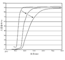
- Patent Document 2 an epoxy resin having relatively good heat resistance, light resistance and connection reliability as a binder resin to be blended in an anisotropic conductive paste or anisotropic conductive film for anisotropic conductive connection of an LED to a substrate ( Patent Document 2) has been widely used, but epoxy resin absorbs light from the near ultraviolet wavelength region to the near infrared region as shown in FIG. 5A due to its molecular structure.
- the molecular chain is broken or oxidized, and the light transmittance spectrum changes greatly as shown by the arrow in FIG.
- the light reflecting layer 40 must be provided on the LED element 33 by a metal vapor deposition method or the like so as to be insulated from the p-electrode 34 and the n-electrode 35, and thus an increase in manufacturing cost is inevitable. There was a problem.
- the surface of the conductive particles covered with gold, nickel, or copper in the cured anisotropic conductive paste or anisotropic conductive film exhibits brown or dark brown
- the epoxy resin binder itself in which the conductive particles are dispersed also exhibits a brown color due to the imidazole-based latent curing agent commonly used for curing, and the light emission efficiency of the light emitted from the light emitting element (light extraction) There is also a problem that it is difficult to improve efficiency.
- silicone resins used as thermosetting resins for anisotropic conductive pastes and anisotropic conductive films do not significantly reduce light reflectance, total LED light flux, or die shear strength due to long-term use of light-emitting devices.
- the initial die shear strength itself immediately after anisotropic conductive connection is low in the first place.
- An object of the present invention is to solve the above-described problems of the prior art, and light-emitting elements such as light-emitting diodes (LEDs) are flip-chip mounted on a wiring board using an anisotropic conductive adhesive to emit light.
- LEDs light-emitting diodes
- An object is to provide an anisotropic conductive adhesive that does not significantly reduce the total luminous flux, and a light-emitting device in which a light-emitting element is flip-chip mounted on a wiring board using the adhesive.
- the inventors of the present invention have assumed that the anisotropic conductive adhesive itself has a light reflecting function, and the light-reflective insulating particles are added to the anisotropic conductive adhesive under the assumption that the luminous efficiency can be prevented.
- By blending it is possible not to decrease the luminous efficiency of the light emitting element, and as a silicone resin blended in the anisotropic conductive adhesive, by using a resin modified with alkenyl glycidyl ether and alkenyl cycloalkane, It has been found that the initial die shear strength is high and the light reflectance, total LED light flux, and die shear strength are not greatly reduced even when the light emitting device is used for a long time, and the present invention has been completed.
- the present invention is a light-reflective anisotropic conductive adhesive used for anisotropic conductive connection of a light emitting element to a wiring board, and a thermosetting resin composition containing a silicone resin and a curing agent.
- a light-reflective anisotropic conductive adhesive comprising conductive particles and light-reflective insulating particles, wherein the silicone resin is a glycidyloxyalkyl alicyclic alkyl-modified organopolysiloxane.
- the present invention provides a particularly preferred embodiment of the light-reflective anisotropic conductive adhesive.
- a light-reflective anisotropic conductive adhesive which is a light-reflective conductive particle comprising a light-reflecting layer formed of at least one inorganic particle selected from zinc oxide particles, silicon oxide particles or aluminum oxide particles, and b) A glycidyloxyalkyl / alicyclic alkyl-modified organopolysiloxane is obtained by hydrosilating an alkenyl glycidyl ether and an alkenylcycloalkane to an alkylhydrogenpolysiloxane, and the curing agent is acid anhydride.
- a light-reflective anisotropic conductive adhesive that is a physical curing agent is provided.
- the present invention also provides a light-emitting device in which a light-emitting element is mounted on a wiring board by a flip-chip method through the above-described light-reflective anisotropic conductive adhesive.
- the light-reflective anisotropic conductive adhesive of the present invention used for anisotropically conductively connecting a light-emitting element to a wiring board contains light-reflective insulating particles. Therefore, this light-reflective anisotropic conductive adhesive can reflect light.
- the light-reflective insulating particles are at least one kind of inorganic particles selected from the group consisting of titanium oxide, boron nitride, zinc oxide, silicon oxide, and aluminum oxide, or the surface of scale-like or spherical metal particles is made of an insulating resin.
- coated resin-coated metal particles since the particles themselves are almost white, the wavelength dependency of the light reflection characteristics with respect to visible light is small, and therefore the light emission efficiency can be improved, and the light emission of the light emitting element is also achieved. The color can be reflected as it is.
- white to gray light formed from core particles coated with a metal material as conductive particles and titanium oxide particles, boron nitride particles, zinc oxide particles, silicon oxide particles, or aluminum oxide particles on the surface thereof.
- a metal material as conductive particles and titanium oxide particles, boron nitride particles, zinc oxide particles, silicon oxide particles, or aluminum oxide particles on the surface thereof.
- the light-reflective conductive particles composed of the reflective layer are used, the light-reflective conductive particles themselves exhibit white to gray, so that the wavelength dependency of the light reflection property with respect to visible light is small.
- the light emission efficiency can be further improved, and the light emission color of the light emitting element can be reflected as it is.
- the light-reflective anisotropic conductive adhesive of the present invention uses glycidyloxyalkyl / alicyclic alkyl-modified organopolysiloxane as a silicone resin. For this reason, the initial die shear strength is high, and the light reflectance, the total amount of light flux of the LED, and the die shear strength are not greatly reduced by long-term use of the light emitting device.
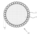
- FIG. 1A is a cross-sectional view of light-reflective conductive particles used in the light-reflective anisotropic conductive adhesive of the present invention.
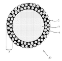
- FIG. 1B is a cross-sectional view of light-reflective conductive particles used in the light-reflective anisotropic conductive adhesive of the present invention.
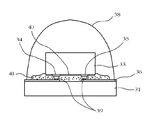
- FIG. 2 is a cross-sectional view of the light emitting device of the present invention.
- FIG. 3 is a cross-sectional view of a conventional light emitting device.
- FIG. 4 is a cross-sectional view of a conventional light emitting device.
- FIG. 5A is a chart showing the light transmittance with respect to the light wavelength of the cured epoxy resin used for the anisotropic conductive adhesive.
- FIG. 5B is a chart showing the light transmittance with respect to the light wavelength after heating UV irradiation of the cured epoxy resin used for the anisotropic conductive adhesive.
- the light-reflective anisotropic conductive adhesive of the present invention is used for anisotropic conductive connection of a light-emitting element to a wiring board, and is a thermosetting resin composition containing at least a silicone resin and a curing agent. It is composed of conductive particles and light-reflective insulating particles, characterized by containing light-reflective insulating particles, and using glycidyloxyalkyl alicyclic alkyl-modified organopolysiloxane as a silicone resin. It is. First, the light reflective insulating particles will be described.
- the light-reflective insulating particles are for reflecting light incident on the anisotropic conductive adhesive to the outside.
- the light-reflective particles include metal particles, particles coated with metal particles, inorganic particles such as metal oxides, metal nitrides, and metal sulfides that are gray to white under natural light, resin core particles
- corrugation on the surface are contained irrespective of the material of particle
- the light-reflective insulating particles that can be used in the present invention do not include metal particles because they are required to exhibit insulating properties.
- Preferred specific examples of such light-reflective insulating particles include titanium oxide (TiO 2 ), boron nitride (BN), zinc oxide (ZnO), silicon oxide (SiO 2 ), and aluminum oxide (Al 2 O 3 ). At least one inorganic particle selected from the group consisting of: Among these, it is preferable to use TiO 2 from the viewpoint of a high refractive index.
- the shape of the light-reflective insulating particles may be spherical, scaly, indeterminate, acicular, etc., but considering the light reflection efficiency, spherical and scaly are preferable.
- the particle size is spherical, if it is too small, the light reflectivity is low, and if it is too large, the anisotropic connection by the conductive particles tends to be hindered, so 0.02 to 20 ⁇ m is preferable.
- the major axis is preferably 0.1 to 100 ⁇ m, more preferably 1 to 50 ⁇ m, and the minor axis is preferably 0.01 to 10 ⁇ m, more preferably 0.
- the thickness is preferably 1 to 5 ⁇ m, and the thickness is preferably 0.01 to 10 ⁇ m, more preferably 0.1 to 5 ⁇ m.
- the refractive index (JIS K7142) of the light-reflective insulating particles made of inorganic particles is preferably larger than the refractive index (JIS K7142) of the cured product of the thermosetting resin composition, and is preferably at least about 0.02 larger. preferable. This is because if the difference in refractive index is small, the light reflection efficiency at the interface between them decreases.
- the inorganic particles described above may be used, but resin-coated metal particles obtained by coating the surface of scale-like or spherical metal particles with a transparent insulating resin may be used.
- the metal particles include nickel, silver, and aluminum.
- the shape of the particles include an amorphous shape, a spherical shape, a scaly shape, and a needle shape. Among these, a spherical shape is preferable from the viewpoint of the light diffusion effect, and a scaly shape is preferable from the viewpoint of the total reflection effect. Particularly preferred are scaly silver particles in terms of light reflectance.
- the size of the resin-coated metal particles as the light-reflective insulating particles varies depending on the shape. Generally, if the size is too large, the anisotropic connection by the conductive particles may be hindered. If the size is too small, it is difficult to reflect light. Therefore, in the case of a spherical shape, the particle diameter is preferably from 0.1 to 30 ⁇ m, more preferably from 0.2 to 10 ⁇ m. In the case of a scale, the long diameter is preferably from 0.1 to 100 ⁇ m, more preferably from 1 to The thickness at 50 ⁇ m is preferably 0.01 to 10 ⁇ m, more preferably 0.1 to 5 ⁇ m.
- the size of the light-reflective insulating particles is the size including the insulating coating when the insulating coating is applied.
- acrylic resins obtained by radical copolymerization of methyl methacrylate and 2-hydroxyethyl methacrylate in the presence of a radical polymerization initiator such as an organic peroxide such as benzoyl peroxide.
- a radical polymerization initiator such as an organic peroxide such as benzoyl peroxide.
- it is more preferable to crosslink with an isocyanate-based crosslinking agent such as 2,4-tolylene diisocyanate.
- metal particles constituting the resin-coated metal particles it is preferable to introduce a ⁇ -glycidoxy group, a vinyl group or the like into the metal surface in advance with a silane coupling agent.
- such resin-coated metal particles are prepared by adding metal particles and a silane coupling agent in a solvent such as toluene and stirring the mixture at room temperature for about 1 hour, and then, if necessary, a radical monomer and a radical polymerization initiator. Then, a crosslinking agent is added, and the mixture is stirred by heating to the radical polymerization starting temperature.
- the content is preferably 1 to 50% by volume, more preferably 2 to 25% by volume with respect to the thermosetting resin composition.
- metal particles used in conventional conductive particles for anisotropic conductive connection can be used.
- examples thereof include gold, nickel, copper, silver, solder, palladium, aluminum, alloys thereof, multilayered products thereof (for example, nickel plating / gold flash plating products), and the like.
- gold, nickel, and copper turn the conductive particles brown, so that the effects of the present invention can be enjoyed over other metal materials.
- Preferable sizes and shapes of such metal particles include spherical particles of 0.2 to 5 ⁇ m, or flaky particles having a thickness of 0.2 to 0.4 ⁇ m and a diameter of 1 to 10 ⁇ m.
- metal-coated resin particles obtained by coating resin particles with a metal material can be used as the conductive particles.
- the resin particles constituting such metal-coated resin particles include styrene resin particles, benzoguanamine resin particles, and nylon resin particles.
- a method of coating the resin particles with a metal material a conventionally known method can be employed, and an electroless plating method, an electrolytic plating method, or the like can be used.
- the layer thickness of the metal material to be coated is sufficient to ensure good connection reliability, and is usually 0.1 to 3 ⁇ m although it depends on the particle size of the resin particles and the type of metal.
- the particle size of the metal-coated resin particles is too small, poor conduction tends to occur, and if it is too large, there is a tendency to cause a short circuit between patterns, so that it is preferably 1 to 20 ⁇ m, more preferably 3 to 10 ⁇ m, and particularly preferably 3 to 5 ⁇ m.
- the shape of the metal-coated resin particles is preferably spherical, but may be a flake shape or a rugby ball shape.
- 1A and 1B are sectional views of such light-reflective conductive particles 10 and 20. First, the light reflective conductive particles in FIG. 1A will be described.
- the light-reflective conductive particles 10 include a core particle 1 coated with a metal material, and titanium oxide (TiO 2 ), boron nitride (BN), zinc oxide (ZnO), silicon oxide (SiO 2 ), and oxide on the surface thereof.
- the light reflecting layer 3 is formed of at least one kind of inorganic particles 2 selected from the group consisting of aluminum (Al 2 O 3 ). Titanium oxide particles, boron nitride particles, zinc oxide particles, silicon oxide particles, and aluminum oxide particles are inorganic particles that exhibit white under sunlight. Accordingly, the light reflecting layer 3 formed from them exhibits white to gray.
- the expression of white to gray means that the wavelength dependence of the light reflection characteristic with respect to visible light is small and the visible light is easily reflected.
- titanium oxide particles Of the titanium oxide particles, boron nitride particles, zinc oxide particles, silicon oxide particles, and aluminum oxide particles, there is a concern about photodegradation of the cured product of the thermosetting resin composition of the cured light-reflective anisotropic conductive adhesive.
- zinc oxide particles that are not catalytic to photodegradation and have a high refractive index can be preferably used.
- the surface thereof is made of a metal material.
- the surface is coated with a metal material, as described above, an aspect in which the core particle 1 itself is a metal material, or an aspect in which the surface of the resin particle is coated with a metal material can be given.
- the layer thickness of the light reflecting layer 3 formed from the inorganic particles 2 is too small with respect to the particle size of the core particle 1.
- the decrease is remarkable, and if it is too large, poor conduction occurs. Therefore, the content is preferably 0.5 to 50%, more preferably 1 to 25%.
- the particle size of the inorganic particles 2 constituting the light-reflecting layer 3 is preferably 0.02 to 4 ⁇ m, more preferably 0.1 to 1 ⁇ m, and particularly preferably 0.2 to 0.5 ⁇ m.
- the particle size of the inorganic particles 2 is set so that the light to be reflected (that is, the light emitted from the light emitting element) is not transmitted. It is preferable that it is 50% or more.
- examples of the shape of the inorganic particles 2 include an amorphous shape, a spherical shape, a scaly shape, and a needle shape.
- a spherical shape is preferable from the viewpoint of the light diffusion effect
- a scaly shape is preferable from the viewpoint of the total reflection effect.
- the light-reflective conductive particles 10 in FIG. 1A are formed by a known film forming technique (so-called mechano-fusion method) in which a film composed of small-sized particles is formed on the surface of large-sized particles by physically colliding large and small powders. ).
- the inorganic particles 2 are fixed so as to bite into the metal material on the surface of the core particle 1.
- the monolayer of the inorganic particles 2 constitutes the light reflecting layer 3.
- the layer thickness of the light reflecting layer 3 is considered to be equivalent to or slightly thinner than the particle size of the inorganic particles 2.
- the light reflective conductive particles 20 in FIG. 1B will be described.
- the light-reflecting layer 3 contains a thermoplastic resin 4 that functions as an adhesive
- the inorganic particles 2 are also fixed together by this thermoplastic resin 4, and the inorganic particles 2 are multilayered (for example, It differs from the light-reflective conductive particle 10 of FIG. 1A in that it is multi-layered into two or three layers.
- the mechanical strength of the light reflecting layer 3 is improved, and the inorganic particles 2 are hardly peeled off.
- thermoplastic resin 4 a halogen-free thermoplastic resin can be preferably used for the purpose of low environmental load, and for example, polyolefins such as polyethylene and polypropylene, polystyrene, acrylic resins and the like can be preferably used.
- Such light-reflective conductive particles 20 can also be manufactured by a mechanofusion method. If the particle size of the thermoplastic resin 4 applied to the mechano-fusion method is too small, the adhesion function is lowered, and if it is too large, it is difficult to adhere to the core particle 1, so that it is preferably 0.02 to 4 ⁇ m, more preferably 0.8. 1 to 1 ⁇ m. Further, if the amount of the thermoplastic resin 4 is too small, the adhesive function is lowered, and if it is too large, aggregates of particles are formed. The amount is 2 to 500 parts by mass, more preferably 4 to 25 parts by mass.
- thermosetting resin composition used for the light-reflective anisotropic conductive adhesive of the present invention it is preferable to use a colorless and transparent one as much as possible. This is because the light-reflecting conductive particles in the light-reflective anisotropic conductive adhesive are reflected without lowering the light reflection efficiency and without changing the light color of the incident light.
- the colorless and transparent means that the cured product of the thermosetting resin composition has a light transmittance (JIS K7105) of 80% or more, preferably 90% or more with respect to visible light having a wavelength of 380 to 780 nm with an optical path length of 1 cm.
- the content is preferably 5 to 30% by volume, more preferably 10 to 20% by volume.
- the light reflection property of the light reflective anisotropic conductive adhesive of the present invention is such that the light reflectance anisotropic conductive adhesive cured product of the light reflective anisotropic conductive adhesive with respect to light having a wavelength of 450 nm ( It is desirable that JIS K7105) is at least 30%.
- the light reflection characteristics and blending amount of the light reflecting conductive particles to be used, the blending composition of the thermosetting resin composition, and the like may be appropriately adjusted. Usually, if the amount of the light-reflective conductive particles having good light reflection characteristics is increased, the light reflectance tends to increase.
- the light reflection characteristics of the light reflective anisotropic conductive adhesive can be evaluated from the viewpoint of refractive index. That is, if the refractive index of the cured product is larger than the refractive index of the cured product of the thermosetting resin composition excluding the conductive particles and the light-reflective insulating particles, the light-reflective insulating particles and the thermosetting surrounding them. This is because the amount of light reflection at the interface with the cured product of the conductive resin composition increases.
- the difference obtained by subtracting the refractive index of the cured product of the thermosetting resin composition (JIS K7142) from the refractive index of the light-reflective insulating particles (JIS K7142) is preferably 0.02 or more, more preferably Is desirably 0.2 or more.
- the refractive index of the cured product of the thermosetting resin composition mainly composed of silicone resin is about 1.40 to 1.55.
- thermosetting resin composition constituting the light-reflective anisotropic conductive adhesive of the present invention contains a glycidyloxyalkyl-alicyclic alkyl-modified organopolysiloxane.
- a glycidyloxyalkyl / alicyclic alkyl-modified organopolysiloxane is obtained by hydrosilating an alkenyl glycidyl ether and an alkenylcycloalkane to an alkylhydrogenpolysiloxane.
- Alkyl hydrogen polysiloxane is a compound for introducing an epoxy group into the side chain of polysiloxane by hydrosilation, and the introduction of an epoxy group causes polysiloxane to have polar groups on its molecular surface.
- the adhesive force of the light-reflective anisotropic conductive adhesive to the adherend can be improved. Further, it can be thermally cured with an acid anhydride curing agent.
- the weight average molecular weight of the alkyl hydrogen polysiloxane is preferably 70000 or less in consideration of handling properties.
- the lower limit is 300 or more due to manufacturing restrictions.
- alkyl hydrogen polysiloxane examples include alkyl groups such as methyl group, ethyl group, propyl group, isopropyl group, butyl group, t-butyl group, and isobutyl group.
- alkyl hydrogen polysiloxanes those having a methyl group are preferred.
- the chemical structure of such methyl hydrogen polysiloxane is shown in Formula (1).
- n is preferably a number from 3 to 40, more preferably from 10 to 35, and particularly preferably from 15 to 28.
- the relationship between m and n is preferably m ⁇ n, and more preferably 2m ⁇ n. This is because when the number of methyl hydrogen silyl groups is larger than that of dimethyl silyl groups, the hydrogen silyl group adjacent to the glycidyloxyalkyl group is sterically hindered when the alkenyl glycidyl ether is hydrosilylated to the hydrogen silyl group. This is because hydrosilylation becomes difficult. Therefore, it is desirable that two or more methyl hydrogen silyl groups do not continue.
- Alkenyl glycidyl ether is a compound for introducing a glycidyloxyalkyl group having an epoxy group into the side chain of polysiloxane by hydrosilation.
- alkenyl group include a vinyl group, an allyl group, and a 1-propenyl group. be able to. Of these, an allyl group is preferred from the viewpoint of high reactivity.
- alkenylcycloalkane is a compound for introducing an alicyclic alkyl group into the side chain of polysiloxane by hydrosilylation, and imparts good transparency to the thermosetting resin composition. Moreover, it becomes possible to adjust the hardness of a thermosetting resin composition by adjusting the kind and abundance of cycloalkane. If the hardness is too soft, there is a concern that stress is applied to the light emitting element due to deformation of the resin during the manufacturing process of the light emitting device or during use after assembly, and the light emitting device may fail.
- Examples of the alkenyl group of the alkenylcycloalkane include a vinyl group, an allyl group, and a 1-propenyl group. Among these, a vinyl group is preferable from the viewpoint of high reactivity.
- examples of the cycloalkane include cyclobutane, cyclopentane, and cyclohexane. Among these, cyclohexane is preferable because it has a heat-resistant and light-resistant skeleton.
- alkenyl glycidyl ether preferably allyl glycidyl ether and alkenyl cycloalkane, preferably vinyl cyclohexane. If the former is too much, the unreacted substance is left in the light-reflective anisotropic conductive adhesive.
- the amount of alkenylcycloalkane is preferably 0.3 to 2 mol, more preferably 0.5 to 1.2 mol, relative to 1 mol of alkenyl glycidyl ether.
- the total amount of alkenyl glycidyl ether and alkenyl cycloalkane used in the hydrosilylation with respect to the alkylhydrogenpolysiloxane is too low in the former. If the amount is too high, characteristics such as die shear strength of the cured product tend to be lowered. Therefore, the total amount of alkenyl glycidyl ether and alkenyl cycloalkane is preferably 0.7 to 1 equivalent to 1 equivalent of alkylhydrogenpolysiloxane (based on hydrogensilyl group). 1.3 equivalents, more preferably 0.9 to 1.1 equivalents.
- the hydrosilylation catalyst includes hexachloroplatinum, platinum-divinyltetramethyldisiloxane complex, platinum divinylsiloxane, platinum cyclic vinylmethylsiloxane, tris (dibenzylideneacetone) diplatinum, chloroplatinic acid, bis (ethylene) tetrachloro. Diplatinum, cyclooctadiene dichloroplatinum, bis (dimethylphenylphosphine) dichloroplatinum, tetrakis (triphenylphosphine) platinum, platinum carbon and the like can be used as appropriate.
- the thermosetting resin composition used in the present invention contains a curing agent for curing the glycidyloxyalkyl alicyclic alkyl-modified organopolysiloxane.
- curing agents include acid anhydride curing agents for curing epoxy resins, imidazole compounds, and dicyan.
- an acid anhydride-based curing agent that hardly changes the color of the cured product, particularly one that does not have a double bond in the molecule is preferable.
- Specific examples include methylhexahydrophthalic anhydride and methyltetrahydrphthalic anhydride.
- the blending amount of the curing agent in the thermosetting resin composition varies depending on the curing mechanism, but in the case of an addition reaction mechanism using an acid anhydride curing agent, the thermo-light characteristics of the cured product may be too little or too much. And properties such as die shear strength tend to be reduced, so that the amount is preferably 50 to 140 parts by mass, more preferably 80 to 120 parts by mass with respect to 100 parts by mass of the glycidyloxyalkyl / alicyclic alkyl-modified organopolysiloxane. .
- thermosetting resin composition constituting the light-reflective anisotropic conductive adhesive of the present invention contains various anti-aging agents such as hindered phenols, aromatic amines, hydroperoxides, metal deactivators, and UV blockers. You may contain.
- the light-reflective anisotropic conductive adhesive of the present invention can be blended with a known epoxy resin or silicone resin within a range that does not impair the effects of the present invention.
- a known epoxy resin or silicone resin examples include dimethylpolysiloxane and diphenylpolysiloxane.
- examples of the epoxy resin include alicyclic epoxy compounds, heterocyclic epoxy compounds, and hydrogenated epoxy compounds.
- Preferred examples of the alicyclic epoxy compound include those having two or more epoxy groups in the molecule. These may be liquid or solid. Specific examples include glycidyl hexahydrobisphenol A, 3,4-epoxycyclohexenylmethyl-3 ′, 4′-epoxycyclohexene carboxylate, and the like. Among them, 3,4-epoxycyclohexenylmethyl-3 ′ having an epoxy group in the ring can ensure light transmittance suitable for mounting LED elements on the cured product and is excellent in rapid curing. 4,4'-epoxycyclohexenecarboxylate can be preferably used.
- heterocyclic epoxy compound examples include an epoxy compound having a triazine ring, and 1,3,5-tris (2,3-epoxypropyl) -1,3,5-triazine-2,4 is particularly preferable. , 6- (1H, 3H, 5H) -trione.
- hydrogenated epoxy compound hydrogenated products of the above-described alicyclic epoxy compounds and heterocyclic epoxy compounds, and other known hydrogenated epoxy resins can be used.
- the alicyclic epoxy compound, heterocyclic epoxy compound and hydrogenated epoxy compound may be used alone, but two or more kinds may be used in combination.
- other epoxy compounds may be used in combination as long as the effects of the present invention are not impaired.
- the light-reflective anisotropic conductive adhesive of the present invention can be produced by uniformly mixing light-reflective insulating particles, conductive particles, and a thermosetting resin composition.
- light-reflective anisotropic conductive films they are dispersed and mixed together with a solvent such as toluene, and applied to a peeled PET film so as to have a desired thickness, and a temperature of about 80 ° C. Just dry.
- the light-emitting device 200 includes the connection terminal 22 on the substrate 21 and the connection bumps 26 formed on the n-electrode 24 and the p-electrode 25 of the LED element 23 as light-emitting elements.
- This is a light-emitting device in which a light-reflective anisotropic conductive adhesive is applied and the substrate 21 and the LED element 23 are mounted by a flip chip method.
- the light-reflective anisotropic conductive adhesive cured product 100 is obtained by dispersing the light-reflective conductive particles 10 in the cured product 11 of the thermosetting resin composition.
- you may provide a light reflection layer in the LED element 23 similarly to the past.
- the light emitting device 200 configured as described above, among the light emitted from the LED elements 23, the light emitted toward the substrate 21 is the light in the cured product 100 of the light-reflective anisotropic conductive adhesive. The light is reflected by the reflective conductive particles 10 and emitted from the upper surface of the LED element 23. Accordingly, it is possible to prevent a decrease in luminous efficiency.
- Configurations other than the light-reflective anisotropic conductive adhesive (the LED element 23, the bump 26, the substrate 21, the connection terminal 22, and the like) in the light-emitting device 200 of the present invention can be the same as the configuration of the conventional light-emitting device. .
- the light emitting device 200 of the present invention can be manufactured by using a conventional anisotropic conductive connection technique except that the light reflective anisotropic conductive adhesive of the present invention is used.
- a well-known light emitting element can be applied in the range which does not impair the effect of this invention other than an LED element.
- methylhydrogensiloxane / dimethylsiloxane copolymer HMS-082, Gelect
- HMS-082 methylhydrogensiloxane / dimethylsiloxane copolymer
- the equivalent ratio of methylhydrogensiloxane / dimethylsiloxane copolymer / allyl glycidyl ether / vinylcyclohexane was 1 / 0.5 / 0.00. 5 was added dropwise to obtain a reaction solution.
- thermosetting resin composition was prepared by uniformly mixing the components (parts by mass) shown in Table 1 excluding the conductive particles and the light-reflective insulating particles using a general desktop stirrer. .
- 10 phr [parts per hundred resin] of Au particles and 30 phr of light-reflective insulating particles are added and mixed uniformly using a table-type stirrer to produce a light-reflective material with a white appearance.
- An anisotropic conductive adhesive was obtained.
- Example 6 is an example using titanium oxide-coated silver particles prepared as described below as light-reflective insulating particles, and Example 7 uses titanium oxide-coated gold particles as light-reflective conductive particles. It is an example used.
- Comparative Example 1 is an example of a light-reflective anisotropic conductive adhesive using an alicyclic epoxy resin without using a silicone resin, and Comparative Examples 2 and 3 use commercially available unmodified silicone resins. It is an example of the light-reflective anisotropic conductive adhesive.
- Comparative Example 4 is an example in which no light-reflective insulating particles are used.
- Example 6 (Titanium oxide-coated silver particles (light-reflective insulating particles) used in Example 6)
- a silane coupling agent 3-methacryloxypropyltriethoxysilane
- Titanium oxide-coated gold particles used in Example 7 Titanium oxide powder with an average particle size of 0.5 ⁇ m and Au coated resin conductive particles with an average particle size of 5 ⁇ m whose appearance color is brown (electroless gold plating of 0.2 ⁇ m thickness is applied to spherical acrylic resin particles with an average particle size of 4.6 ⁇ m)
- the particles were introduced into a mechanofusion apparatus, and a light reflective layer made of titanium oxide particles having a thickness of about 0.5 ⁇ m was formed on the surface of the conductive particles to obtain light reflective conductive particles.
- the appearance color of the light reflective conductive particles was gray.
- the obtained light-reflective anisotropic conductive adhesive was subjected to light reflectivity measurement, total luminous flux measurement, die shear strength measurement, and conduction light emission confirmation test as described below.
- the die shear strength of the light-reflective anisotropic conductive adhesive at the initial stage of light emission and after 1000 hours of light emission (after aging) was measured at a shear rate of 20 ⁇ m / sec using a die shear strength measuring device (PTR-1100, RHESCA). Measured with The obtained results are shown in Table 1. It is desired that the die shear strength is practically 70 N / chip or more. Further, it is desirable that the die shear strength reduction rate before and after aging is 10% or less.
- the light reflectivity is 30% or more, and the reduction rate before and after aging. was 20% or less, and the blue color of 450 nm light was reflected as it was.
- the total luminous flux was 250 mlm or more in the initial stage, and the reduction rate before and after aging was 15% or less.
- the die shear strength was 70 N / chip or more in all cases, and the decrease rate before and after aging was 10% or less.
- no abnormality was observed in the conduction light emission confirmation test.
- the light-reflective anisotropic conductive adhesive of the present invention is used for manufacturing a light-emitting device by mounting a light-emitting element such as a light-emitting diode (LED) element on a wiring board by a flip-chip method using an anisotropic conductive adhesive.
- a light-emitting element such as a light-emitting diode (LED) element
- LED light-emitting diode
- the light-reflective anisotropic conductive adhesive of the present invention is useful when flip-chip mounting an LED element.
Priority Applications (4)
| Application Number | Priority Date | Filing Date | Title |
|---|---|---|---|
| EP12757068.7A EP2584015B1 (en) | 2011-03-16 | 2012-03-14 | Light-reflecting anisotropically conductive adhesive and light emitting device |
| US13/805,238 US8852462B2 (en) | 2011-03-16 | 2012-03-14 | Light-reflective anisotropic conductive adhesive and light-emitting device |
| CN201280013511.6A CN103415585B (zh) | 2011-03-16 | 2012-03-14 | 反光性各向异性导电粘接剂及发光装置 |
| KR1020137004146A KR101995599B1 (ko) | 2011-03-16 | 2012-03-14 | 광 반사성 이방성 도전 접착제 및 발광 장치 |
Applications Claiming Priority (2)
| Application Number | Priority Date | Filing Date | Title |
|---|---|---|---|
| JP2011057818 | 2011-03-16 | ||
| JP2011-057818 | 2011-03-16 |
Publications (1)
| Publication Number | Publication Date |
|---|---|
| WO2012124724A1 true WO2012124724A1 (ja) | 2012-09-20 |
Family
ID=46830789
Family Applications (1)
| Application Number | Title | Priority Date | Filing Date |
|---|---|---|---|
| PCT/JP2012/056520 WO2012124724A1 (ja) | 2011-03-16 | 2012-03-14 | 光反射性異方性導電接着剤及び発光装置 |
Country Status (7)
| Country | Link |
|---|---|
| US (1) | US8852462B2 (zh) |
| EP (1) | EP2584015B1 (zh) |
| JP (1) | JP5888023B2 (zh) |
| KR (1) | KR101995599B1 (zh) |
| CN (1) | CN103415585B (zh) |
| TW (1) | TWI529981B (zh) |
| WO (1) | WO2012124724A1 (zh) |
Cited By (5)
| Publication number | Priority date | Publication date | Assignee | Title |
|---|---|---|---|---|
| JP2014029856A (ja) * | 2012-07-03 | 2014-02-13 | Sekisui Chem Co Ltd | 絶縁性粒子付き導電性粒子、導電材料及び接続構造体 |
| GB2504957A (en) * | 2012-08-14 | 2014-02-19 | Henkel Ag & Co Kgaa | Curable compositions comprising composite particles |
| US20150166847A1 (en) * | 2012-06-15 | 2015-06-18 | Dexerials Corporation | Light-reflective anisotropic conductive adhesive and light-emitting device |
| EP2899244A4 (en) * | 2012-09-24 | 2016-06-01 | Dexerials Corp | ANISOTROPIC CONDUCTIVE ADHESIVE AND JUNCTION STRUCTURE |
| WO2018008693A1 (ja) * | 2016-07-07 | 2018-01-11 | デクセリアルズ株式会社 | 絶縁被覆粒子、絶縁被覆粒子の製造方法、粒子含有組成物、及び異方性導電接着剤 |
Families Citing this family (24)
| Publication number | Priority date | Publication date | Assignee | Title |
|---|---|---|---|---|
| JP5617210B2 (ja) * | 2009-09-14 | 2014-11-05 | デクセリアルズ株式会社 | 光反射性異方性導電接着剤及び発光装置 |
| KR101375298B1 (ko) * | 2011-12-20 | 2014-03-19 | 제일모직주식회사 | 전도성 미립자 및 이를 포함하는 이방 전도성 필름 |
| JP6003763B2 (ja) * | 2012-10-30 | 2016-10-05 | デクセリアルズ株式会社 | 熱硬化性樹脂組成物、光反射性異方性導電接着剤及び発光装置 |
| EP3004230B1 (en) * | 2013-06-06 | 2016-10-05 | Philips Lighting Holding B.V. | Reflective composition |
| KR101611003B1 (ko) | 2013-06-28 | 2016-04-20 | 제일모직주식회사 | 실리콘 엘라스토머를 포함하는 이방 도전성 필름 |
| JP6115457B2 (ja) * | 2013-12-05 | 2017-04-19 | デクセリアルズ株式会社 | グリシジルイソシアヌリル変性ポリシロキサンの製造方法 |
| JP6384046B2 (ja) * | 2013-12-06 | 2018-09-05 | デクセリアルズ株式会社 | 光反射性異方性導電接着剤及び発光装置 |
| US9812625B2 (en) | 2014-02-18 | 2017-11-07 | Nichia Corporation | Light-emitting device having resin member with conductive particles |
| US9706667B2 (en) * | 2014-05-19 | 2017-07-11 | Sierra Circuits, Inc. | Via in a printed circuit board |
| US10516085B2 (en) * | 2014-08-21 | 2019-12-24 | Luminus, Inc. | Devices and methods including an LED and reflective die attach material |
| EP2988341B1 (en) * | 2014-08-22 | 2017-04-05 | LG Innotek Co., Ltd. | Light emitting device package |
| US10062660B2 (en) | 2015-03-04 | 2018-08-28 | Trillion Science, Inc. | Anisotropic conductive film including a reflective layer |
| US9871177B2 (en) | 2015-03-04 | 2018-01-16 | Trillion Science, Inc. | Anisotropic conductive film (ACF) including a relfective layer |
| JP2016207739A (ja) * | 2015-04-17 | 2016-12-08 | 株式会社東芝 | 半導体発光装置及びその製造方法 |
| JP6368288B2 (ja) * | 2015-08-07 | 2018-08-01 | 福田金属箔粉工業株式会社 | フレーク状銀粒子の集合体及び該銀粒子の集合体を含有するペースト |
| US20200313049A1 (en) * | 2016-06-21 | 2020-10-01 | Soraa, Inc. | Light emitting diode package |
| JP2018177987A (ja) * | 2017-04-13 | 2018-11-15 | サンユレック株式会社 | 導電材料 |
| JP7014948B2 (ja) * | 2017-06-13 | 2022-02-02 | 日亜化学工業株式会社 | 発光装置の製造方法および発光装置 |
| CN107880268A (zh) * | 2017-12-26 | 2018-04-06 | 烟台德邦先进硅材料有限公司 | 一种有机硅环氧杂化增韧剂的合成方法 |
| CN111788275B (zh) * | 2018-03-01 | 2021-12-03 | 住友电木株式会社 | 糊状粘接剂组合物和半导体装置 |
| CN209672120U (zh) * | 2018-10-18 | 2019-11-22 | 漳州立达信灯具有限公司 | 一种用于面板灯的光学件及面板灯 |
| DE102018132955A1 (de) * | 2018-12-19 | 2020-06-25 | Osram Opto Semiconductors Gmbh | Strahlungsemittierendes bauelement |
| JP7390236B2 (ja) * | 2020-03-31 | 2023-12-01 | 京セラ株式会社 | 異方導電性樹脂組成物、及びマイクロledディスプレイ装置 |
| US20220140211A1 (en) * | 2020-10-30 | 2022-05-05 | Nichia Corporation | Light emitting device and method of manufacturing light emitting device |
Citations (8)
| Publication number | Priority date | Publication date | Assignee | Title |
|---|---|---|---|---|
| JPH04259766A (ja) * | 1991-02-14 | 1992-09-16 | Hitachi Chem Co Ltd | 回路の接続部材 |
| JPH11168235A (ja) | 1997-12-05 | 1999-06-22 | Toyoda Gosei Co Ltd | 発光ダイオード |
| JP2001332124A (ja) * | 2000-05-22 | 2001-11-30 | Toshiba Chem Corp | 導電性ペーストおよび光半導体装置 |
| JP2004179139A (ja) * | 2002-09-30 | 2004-06-24 | Sumitomo Osaka Cement Co Ltd | 導電性粒子とそれを含有する導電性接着材料及び透明導電膜形成用塗料及びそれを用いた透明導電膜並びに表示装置 |
| JP2004292779A (ja) * | 2002-04-26 | 2004-10-21 | Kanegafuchi Chem Ind Co Ltd | 硬化性組成物、硬化物、その製造方法およびその硬化物により封止された発光ダイオード |
| JP2005272492A (ja) * | 2004-03-22 | 2005-10-06 | Shin Etsu Chem Co Ltd | 硬化性シリコーン組成物 |
| JP2007123613A (ja) * | 2005-10-28 | 2007-05-17 | Nichia Chem Ind Ltd | 発光装置 |
| JP2010024301A (ja) | 2008-07-16 | 2010-02-04 | Sony Chemical & Information Device Corp | 異方性導電接着剤 |
Family Cites Families (9)
| Publication number | Priority date | Publication date | Assignee | Title |
|---|---|---|---|---|
| US6599631B2 (en) * | 2001-01-26 | 2003-07-29 | Nanogram Corporation | Polymer-inorganic particle composites |
| JP4019254B2 (ja) * | 2002-04-24 | 2007-12-12 | 信越化学工業株式会社 | 導電性樹脂組成物 |
| ATE383404T1 (de) | 2002-04-26 | 2008-01-15 | Kaneka Corp | Härtbare zusammensetzung, härtendes produkt, herstellungsverfahren dafür und mit dem härtenden produkt versiegelte lichtemittierende diode |
| US7312261B2 (en) * | 2004-05-11 | 2007-12-25 | International Business Machines Corporation | Thermal interface adhesive and rework |
| JP4803350B2 (ja) * | 2005-06-03 | 2011-10-26 | 信越化学工業株式会社 | 圧着性異方導電性樹脂組成物及び微細電極の接続方法 |
| JP2008274004A (ja) * | 2007-04-25 | 2008-11-13 | Kaneka Corp | 硬化性樹脂組成物およびその硬化物 |
| KR20090108550A (ko) * | 2008-04-11 | 2009-10-15 | 신에쓰 가가꾸 고교 가부시끼가이샤 | 반도체 소자용 실리콘 접착제 |
| MY157233A (en) * | 2009-03-11 | 2016-05-13 | Shinetsu Chemical Co | Connection sheet for solar battery cell electrode, process for manufacturing solar cell module, and solar cell module |
| CN101851478B (zh) * | 2010-04-29 | 2012-11-21 | 黄文迎 | 一种快速固化导电胶粘剂组合物及其制备方法 |
-
2012
- 2012-03-14 JP JP2012056858A patent/JP5888023B2/ja active Active
- 2012-03-14 WO PCT/JP2012/056520 patent/WO2012124724A1/ja active Application Filing
- 2012-03-14 CN CN201280013511.6A patent/CN103415585B/zh active Active
- 2012-03-14 EP EP12757068.7A patent/EP2584015B1/en active Active
- 2012-03-14 US US13/805,238 patent/US8852462B2/en active Active
- 2012-03-14 KR KR1020137004146A patent/KR101995599B1/ko active IP Right Grant
- 2012-03-15 TW TW101108820A patent/TWI529981B/zh active
Patent Citations (8)
| Publication number | Priority date | Publication date | Assignee | Title |
|---|---|---|---|---|
| JPH04259766A (ja) * | 1991-02-14 | 1992-09-16 | Hitachi Chem Co Ltd | 回路の接続部材 |
| JPH11168235A (ja) | 1997-12-05 | 1999-06-22 | Toyoda Gosei Co Ltd | 発光ダイオード |
| JP2001332124A (ja) * | 2000-05-22 | 2001-11-30 | Toshiba Chem Corp | 導電性ペーストおよび光半導体装置 |
| JP2004292779A (ja) * | 2002-04-26 | 2004-10-21 | Kanegafuchi Chem Ind Co Ltd | 硬化性組成物、硬化物、その製造方法およびその硬化物により封止された発光ダイオード |
| JP2004179139A (ja) * | 2002-09-30 | 2004-06-24 | Sumitomo Osaka Cement Co Ltd | 導電性粒子とそれを含有する導電性接着材料及び透明導電膜形成用塗料及びそれを用いた透明導電膜並びに表示装置 |
| JP2005272492A (ja) * | 2004-03-22 | 2005-10-06 | Shin Etsu Chem Co Ltd | 硬化性シリコーン組成物 |
| JP2007123613A (ja) * | 2005-10-28 | 2007-05-17 | Nichia Chem Ind Ltd | 発光装置 |
| JP2010024301A (ja) | 2008-07-16 | 2010-02-04 | Sony Chemical & Information Device Corp | 異方性導電接着剤 |
Non-Patent Citations (1)
| Title |
|---|
| See also references of EP2584015A4 |
Cited By (8)
| Publication number | Priority date | Publication date | Assignee | Title |
|---|---|---|---|---|
| US20150166847A1 (en) * | 2012-06-15 | 2015-06-18 | Dexerials Corporation | Light-reflective anisotropic conductive adhesive and light-emitting device |
| US10246613B2 (en) * | 2012-06-15 | 2019-04-02 | Dexerials Corporation | Light-reflective anisotropic conductive adhesive and light-emitting device |
| JP2014029856A (ja) * | 2012-07-03 | 2014-02-13 | Sekisui Chem Co Ltd | 絶縁性粒子付き導電性粒子、導電材料及び接続構造体 |
| GB2504957A (en) * | 2012-08-14 | 2014-02-19 | Henkel Ag & Co Kgaa | Curable compositions comprising composite particles |
| US9914855B2 (en) | 2012-08-14 | 2018-03-13 | Henkel Ag & Co. Kgaa | Curable compositions comprising composite particles |
| EP2899244A4 (en) * | 2012-09-24 | 2016-06-01 | Dexerials Corp | ANISOTROPIC CONDUCTIVE ADHESIVE AND JUNCTION STRUCTURE |
| WO2018008693A1 (ja) * | 2016-07-07 | 2018-01-11 | デクセリアルズ株式会社 | 絶縁被覆粒子、絶縁被覆粒子の製造方法、粒子含有組成物、及び異方性導電接着剤 |
| JP2018006278A (ja) * | 2016-07-07 | 2018-01-11 | デクセリアルズ株式会社 | 絶縁被覆粒子、絶縁被覆粒子の製造方法、粒子含有組成物、及び異方性導電接着剤 |
Also Published As
| Publication number | Publication date |
|---|---|
| KR20130131299A (ko) | 2013-12-03 |
| JP5888023B2 (ja) | 2016-03-16 |
| US20130087825A1 (en) | 2013-04-11 |
| TWI529981B (zh) | 2016-04-11 |
| EP2584015B1 (en) | 2016-11-02 |
| CN103415585B (zh) | 2015-04-29 |
| CN103415585A (zh) | 2013-11-27 |
| EP2584015A4 (en) | 2014-01-08 |
| US8852462B2 (en) | 2014-10-07 |
| TW201242118A (en) | 2012-10-16 |
| JP2012207216A (ja) | 2012-10-25 |
| KR101995599B1 (ko) | 2019-07-02 |
| EP2584015A1 (en) | 2013-04-24 |
Similar Documents
| Publication | Publication Date | Title |
|---|---|---|
| JP5888023B2 (ja) | 光反射性異方性導電接着剤及び発光装置 | |
| JP5958107B2 (ja) | 光反射性異方性導電接着剤及び発光装置 | |
| JP5617210B2 (ja) | 光反射性異方性導電接着剤及び発光装置 | |
| JP5402804B2 (ja) | 発光装置の製造方法 | |
| KR101829475B1 (ko) | 광반사성 이방성 도전 페이스트 및 발광 장치 | |
| WO2012121021A1 (ja) | 光反射性異方性導電接着剤及び発光装置 | |
| WO2011045962A1 (ja) | 光反射性導電粒子、異方性導電接着剤及び発光装置 | |
| KR102139124B1 (ko) | 열경화성 수지 조성물, 광반사성 이방성 도전 접착제 및 발광 장치 | |
| WO2012144033A1 (ja) | 光反射性導電粒子、異方性導電接着剤及び発光装置 | |
| WO2014013984A1 (ja) | 光反射性異方性導電接着剤及び発光装置 | |
| JP6115457B2 (ja) | グリシジルイソシアヌリル変性ポリシロキサンの製造方法 | |
| JP6384046B2 (ja) | 光反射性異方性導電接着剤及び発光装置 |
Legal Events
| Date | Code | Title | Description |
|---|---|---|---|
| 121 | Ep: the epo has been informed by wipo that ep was designated in this application |
Ref document number: 12757068 Country of ref document: EP Kind code of ref document: A1 |
|
| WWE | Wipo information: entry into national phase |
Ref document number: 13805238 Country of ref document: US |
|
| REEP | Request for entry into the european phase |
Ref document number: 2012757068 Country of ref document: EP |
|
| WWE | Wipo information: entry into national phase |
Ref document number: 2012757068 Country of ref document: EP |
|
| ENP | Entry into the national phase |
Ref document number: 20137004146 Country of ref document: KR Kind code of ref document: A |
|
| NENP | Non-entry into the national phase |
Ref country code: DE |