WO2012121069A1 - 燃料電池車両の吸気装置 - Google Patents
燃料電池車両の吸気装置 Download PDFInfo
- Publication number
- WO2012121069A1 WO2012121069A1 PCT/JP2012/055018 JP2012055018W WO2012121069A1 WO 2012121069 A1 WO2012121069 A1 WO 2012121069A1 JP 2012055018 W JP2012055018 W JP 2012055018W WO 2012121069 A1 WO2012121069 A1 WO 2012121069A1
- Authority
- WO
- WIPO (PCT)
- Prior art keywords
- fuel cell
- vehicle
- intake
- air intake
- air
- Prior art date
- Legal status (The legal status is an assumption and is not a legal conclusion. Google has not performed a legal analysis and makes no representation as to the accuracy of the status listed.)
- Ceased
Links
Images


Classifications
-
- B—PERFORMING OPERATIONS; TRANSPORTING
- B60—VEHICLES IN GENERAL
- B60K—ARRANGEMENT OR MOUNTING OF PROPULSION UNITS OR OF TRANSMISSIONS IN VEHICLES; ARRANGEMENT OR MOUNTING OF PLURAL DIVERSE PRIME-MOVERS IN VEHICLES; AUXILIARY DRIVES FOR VEHICLES; INSTRUMENTATION OR DASHBOARDS FOR VEHICLES; ARRANGEMENTS IN CONNECTION WITH COOLING, AIR INTAKE, GAS EXHAUST OR FUEL SUPPLY OF PROPULSION UNITS IN VEHICLES
- B60K11/00—Arrangement in connection with cooling of propulsion units
- B60K11/02—Arrangement in connection with cooling of propulsion units with liquid cooling
-
- B—PERFORMING OPERATIONS; TRANSPORTING
- B60—VEHICLES IN GENERAL
- B60L—PROPULSION OF ELECTRICALLY-PROPELLED VEHICLES; SUPPLYING ELECTRIC POWER FOR AUXILIARY EQUIPMENT OF ELECTRICALLY-PROPELLED VEHICLES; ELECTRODYNAMIC BRAKE SYSTEMS FOR VEHICLES IN GENERAL; MAGNETIC SUSPENSION OR LEVITATION FOR VEHICLES; MONITORING OPERATING VARIABLES OF ELECTRICALLY-PROPELLED VEHICLES; ELECTRIC SAFETY DEVICES FOR ELECTRICALLY-PROPELLED VEHICLES
- B60L50/00—Electric propulsion with power supplied within the vehicle
- B60L50/50—Electric propulsion with power supplied within the vehicle using propulsion power supplied by batteries or fuel cells
-
- B—PERFORMING OPERATIONS; TRANSPORTING
- B60—VEHICLES IN GENERAL
- B60K—ARRANGEMENT OR MOUNTING OF PROPULSION UNITS OR OF TRANSMISSIONS IN VEHICLES; ARRANGEMENT OR MOUNTING OF PLURAL DIVERSE PRIME-MOVERS IN VEHICLES; AUXILIARY DRIVES FOR VEHICLES; INSTRUMENTATION OR DASHBOARDS FOR VEHICLES; ARRANGEMENTS IN CONNECTION WITH COOLING, AIR INTAKE, GAS EXHAUST OR FUEL SUPPLY OF PROPULSION UNITS IN VEHICLES
- B60K1/00—Arrangement or mounting of electrical propulsion units
- B60K1/04—Arrangement or mounting of electrical propulsion units of the electric storage means for propulsion
-
- B—PERFORMING OPERATIONS; TRANSPORTING
- B60—VEHICLES IN GENERAL
- B60K—ARRANGEMENT OR MOUNTING OF PROPULSION UNITS OR OF TRANSMISSIONS IN VEHICLES; ARRANGEMENT OR MOUNTING OF PLURAL DIVERSE PRIME-MOVERS IN VEHICLES; AUXILIARY DRIVES FOR VEHICLES; INSTRUMENTATION OR DASHBOARDS FOR VEHICLES; ARRANGEMENTS IN CONNECTION WITH COOLING, AIR INTAKE, GAS EXHAUST OR FUEL SUPPLY OF PROPULSION UNITS IN VEHICLES
- B60K11/00—Arrangement in connection with cooling of propulsion units
- B60K11/02—Arrangement in connection with cooling of propulsion units with liquid cooling
- B60K11/04—Arrangement or mounting of radiators, radiator shutters, or radiator blinds
-
- B—PERFORMING OPERATIONS; TRANSPORTING
- B60—VEHICLES IN GENERAL
- B60K—ARRANGEMENT OR MOUNTING OF PROPULSION UNITS OR OF TRANSMISSIONS IN VEHICLES; ARRANGEMENT OR MOUNTING OF PLURAL DIVERSE PRIME-MOVERS IN VEHICLES; AUXILIARY DRIVES FOR VEHICLES; INSTRUMENTATION OR DASHBOARDS FOR VEHICLES; ARRANGEMENTS IN CONNECTION WITH COOLING, AIR INTAKE, GAS EXHAUST OR FUEL SUPPLY OF PROPULSION UNITS IN VEHICLES
- B60K11/00—Arrangement in connection with cooling of propulsion units
- B60K11/08—Air inlets for cooling; Shutters or blinds therefor
-
- B—PERFORMING OPERATIONS; TRANSPORTING
- B60—VEHICLES IN GENERAL
- B60K—ARRANGEMENT OR MOUNTING OF PROPULSION UNITS OR OF TRANSMISSIONS IN VEHICLES; ARRANGEMENT OR MOUNTING OF PLURAL DIVERSE PRIME-MOVERS IN VEHICLES; AUXILIARY DRIVES FOR VEHICLES; INSTRUMENTATION OR DASHBOARDS FOR VEHICLES; ARRANGEMENTS IN CONNECTION WITH COOLING, AIR INTAKE, GAS EXHAUST OR FUEL SUPPLY OF PROPULSION UNITS IN VEHICLES
- B60K13/00—Arrangement in connection with combustion air intake or gas exhaust of propulsion units
- B60K13/02—Arrangement in connection with combustion air intake or gas exhaust of propulsion units concerning intake
-
- B—PERFORMING OPERATIONS; TRANSPORTING
- B60—VEHICLES IN GENERAL
- B60K—ARRANGEMENT OR MOUNTING OF PROPULSION UNITS OR OF TRANSMISSIONS IN VEHICLES; ARRANGEMENT OR MOUNTING OF PLURAL DIVERSE PRIME-MOVERS IN VEHICLES; AUXILIARY DRIVES FOR VEHICLES; INSTRUMENTATION OR DASHBOARDS FOR VEHICLES; ARRANGEMENTS IN CONNECTION WITH COOLING, AIR INTAKE, GAS EXHAUST OR FUEL SUPPLY OF PROPULSION UNITS IN VEHICLES
- B60K8/00—Arrangement or mounting of propulsion units not provided for in one of main groups B60K1/00 - B60K7/00
-
- H—ELECTRICITY
- H01—ELECTRIC ELEMENTS
- H01M—PROCESSES OR MEANS, e.g. BATTERIES, FOR THE DIRECT CONVERSION OF CHEMICAL ENERGY INTO ELECTRICAL ENERGY
- H01M8/00—Fuel cells; Manufacture thereof
-
- H—ELECTRICITY
- H01—ELECTRIC ELEMENTS
- H01M—PROCESSES OR MEANS, e.g. BATTERIES, FOR THE DIRECT CONVERSION OF CHEMICAL ENERGY INTO ELECTRICAL ENERGY
- H01M8/00—Fuel cells; Manufacture thereof
- H01M8/04—Auxiliary arrangements, e.g. for control of pressure or for circulation of fluids
-
- H—ELECTRICITY
- H01—ELECTRIC ELEMENTS
- H01M—PROCESSES OR MEANS, e.g. BATTERIES, FOR THE DIRECT CONVERSION OF CHEMICAL ENERGY INTO ELECTRICAL ENERGY
- H01M8/00—Fuel cells; Manufacture thereof
- H01M8/04—Auxiliary arrangements, e.g. for control of pressure or for circulation of fluids
- H01M8/04082—Arrangements for control of reactant parameters, e.g. pressure or concentration
- H01M8/04089—Arrangements for control of reactant parameters, e.g. pressure or concentration of gaseous reactants
-
- H—ELECTRICITY
- H01—ELECTRIC ELEMENTS
- H01M—PROCESSES OR MEANS, e.g. BATTERIES, FOR THE DIRECT CONVERSION OF CHEMICAL ENERGY INTO ELECTRICAL ENERGY
- H01M8/00—Fuel cells; Manufacture thereof
- H01M8/24—Grouping of fuel cells, e.g. stacking of fuel cells
- H01M8/2465—Details of groupings of fuel cells
-
- B—PERFORMING OPERATIONS; TRANSPORTING
- B60—VEHICLES IN GENERAL
- B60K—ARRANGEMENT OR MOUNTING OF PROPULSION UNITS OR OF TRANSMISSIONS IN VEHICLES; ARRANGEMENT OR MOUNTING OF PLURAL DIVERSE PRIME-MOVERS IN VEHICLES; AUXILIARY DRIVES FOR VEHICLES; INSTRUMENTATION OR DASHBOARDS FOR VEHICLES; ARRANGEMENTS IN CONNECTION WITH COOLING, AIR INTAKE, GAS EXHAUST OR FUEL SUPPLY OF PROPULSION UNITS IN VEHICLES
- B60K1/00—Arrangement or mounting of electrical propulsion units
- B60K1/04—Arrangement or mounting of electrical propulsion units of the electric storage means for propulsion
- B60K2001/0405—Arrangement or mounting of electrical propulsion units of the electric storage means for propulsion characterised by their position
- B60K2001/0411—Arrangement in the front part of the vehicle
-
- H—ELECTRICITY
- H01—ELECTRIC ELEMENTS
- H01M—PROCESSES OR MEANS, e.g. BATTERIES, FOR THE DIRECT CONVERSION OF CHEMICAL ENERGY INTO ELECTRICAL ENERGY
- H01M2250/00—Fuel cells for particular applications; Specific features of fuel cell system
- H01M2250/20—Fuel cells in motive systems, e.g. vehicle, ship, plane
-
- H—ELECTRICITY
- H01—ELECTRIC ELEMENTS
- H01M—PROCESSES OR MEANS, e.g. BATTERIES, FOR THE DIRECT CONVERSION OF CHEMICAL ENERGY INTO ELECTRICAL ENERGY
- H01M8/00—Fuel cells; Manufacture thereof
- H01M8/24—Grouping of fuel cells, e.g. stacking of fuel cells
- H01M8/2465—Details of groupings of fuel cells
- H01M8/2484—Details of groupings of fuel cells characterised by external manifolds
- H01M8/2485—Arrangements for sealing external manifolds; Arrangements for mounting external manifolds around a stack
-
- Y—GENERAL TAGGING OF NEW TECHNOLOGICAL DEVELOPMENTS; GENERAL TAGGING OF CROSS-SECTIONAL TECHNOLOGIES SPANNING OVER SEVERAL SECTIONS OF THE IPC; TECHNICAL SUBJECTS COVERED BY FORMER USPC CROSS-REFERENCE ART COLLECTIONS [XRACs] AND DIGESTS
- Y02—TECHNOLOGIES OR APPLICATIONS FOR MITIGATION OR ADAPTATION AGAINST CLIMATE CHANGE
- Y02E—REDUCTION OF GREENHOUSE GAS [GHG] EMISSIONS, RELATED TO ENERGY GENERATION, TRANSMISSION OR DISTRIBUTION
- Y02E60/00—Enabling technologies; Technologies with a potential or indirect contribution to GHG emissions mitigation
- Y02E60/30—Hydrogen technology
- Y02E60/50—Fuel cells
-
- Y—GENERAL TAGGING OF NEW TECHNOLOGICAL DEVELOPMENTS; GENERAL TAGGING OF CROSS-SECTIONAL TECHNOLOGIES SPANNING OVER SEVERAL SECTIONS OF THE IPC; TECHNICAL SUBJECTS COVERED BY FORMER USPC CROSS-REFERENCE ART COLLECTIONS [XRACs] AND DIGESTS
- Y02—TECHNOLOGIES OR APPLICATIONS FOR MITIGATION OR ADAPTATION AGAINST CLIMATE CHANGE
- Y02T—CLIMATE CHANGE MITIGATION TECHNOLOGIES RELATED TO TRANSPORTATION
- Y02T10/00—Road transport of goods or passengers
- Y02T10/60—Other road transportation technologies with climate change mitigation effect
- Y02T10/70—Energy storage systems for electromobility, e.g. batteries
-
- Y—GENERAL TAGGING OF NEW TECHNOLOGICAL DEVELOPMENTS; GENERAL TAGGING OF CROSS-SECTIONAL TECHNOLOGIES SPANNING OVER SEVERAL SECTIONS OF THE IPC; TECHNICAL SUBJECTS COVERED BY FORMER USPC CROSS-REFERENCE ART COLLECTIONS [XRACs] AND DIGESTS
- Y02—TECHNOLOGIES OR APPLICATIONS FOR MITIGATION OR ADAPTATION AGAINST CLIMATE CHANGE
- Y02T—CLIMATE CHANGE MITIGATION TECHNOLOGIES RELATED TO TRANSPORTATION
- Y02T90/00—Enabling technologies or technologies with a potential or indirect contribution to GHG emissions mitigation
- Y02T90/40—Application of hydrogen technology to transportation, e.g. using fuel cells
Definitions
- the present invention relates to an intake device for a fuel cell vehicle, and more particularly, to an intake device for a fuel cell vehicle in which the intake amount of the fuel cell is stabilized and water or snow is prevented from entering.
- a fuel cell including a fuel cell stack in which a plurality of fuel cells are stacked is mounted as a driving energy source.
- a fuel cell case containing the fuel cell is disposed in the front of the vehicle, and the air intake surface of the fuel cell Is directed to the front of the vehicle, and an intake duct is attached to the front portion of the fuel cell case, and the air sucked into the intake duct is supplied to the fuel cell as a reaction gas.
- the air intake device described in Patent Document 1 has a problem that rainwater, snow, and the like easily enter the air intake duct during traveling because the air intake port faces the front of the vehicle.
- the intake device described in Patent Document 1 has a problem that the amount of air intake changes due to the influence of the traveling speed because the traveling wind tends to enter the air intake port facing the front of the vehicle.
- the air intake device described in Patent Document 1 has a blower for taking in air, and controls the blower to adjust the amount of air taken in, so that the structure is complicated.
- the intake device described in Patent Document 1 has a structure in which an intake duct is linearly extended from the fuel cell to the front of the vehicle, and an air intake port at the front end of the extension is opened at the front end of the vehicle. For this reason, the intake device described in Patent Document 1 has a shape in which the intake duct is not easily deformed in the vehicle front-rear direction and easily receives a force from the front of the vehicle. There is a problem that the force acts directly on the fuel cell through the intake duct.
- the present invention relates to an intake device for a fuel cell vehicle that supplies air as a reaction gas to a fuel cell through an intake duct, and makes it easy to adjust the air intake amount and protect the fuel cell in the event of a frontal collision of the vehicle. Is the purpose.
- a fuel cell case containing a fuel cell is disposed in a front portion of a vehicle, an air intake surface of the fuel cell is directed forward of the vehicle, an intake duct is attached to a front portion of the fuel cell case, and the intake air
- the intake duct includes a pair of upper and lower upper and bottom walls, and a pair of left and right side walls, and the upper wall Is curved downward as it moves away from the front surface of the fuel cell case toward the front of the vehicle, and an air intake opening is formed between the lower end portion of the upper wall and the front end portion of the bottom wall.
- the intake device for a fuel cell vehicle according to the present invention has a structure in which the air intake port of the intake duct is opened downward in the vehicle, the air intake amount to the intake duct does not change depending on the traveling speed of the vehicle, and the adjustment of the air intake amount Can be made easier. Further, the intake device for a fuel cell vehicle according to the present invention can prevent water or snow flowing from the front of the vehicle to the intake duct side from entering the intake duct.
- the air intake is shaped so as to be easily deformed in the longitudinal direction of the vehicle and disposed at the front end of the intake duct, so that the intake duct is easily crushed by the impact force from the front of the vehicle. . For this reason, the shock absorption at the time of frontal collision can be improved and a fuel cell can be protected.
- FIG. 1 is a right side view of the front portion of the fuel cell vehicle.
- FIG. 2 is a right side view of the intake device of the fuel cell vehicle.
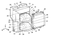
- FIG. 3 is a perspective view from the upper right front of the intake device of the fuel cell vehicle.
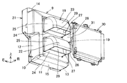
- FIG. 4 is a perspective view from the lower right front of the intake device of the fuel cell vehicle.
- FIG. 1 1 is a fuel cell vehicle
- 2 is a front bumper
- 3 is a front grille opening
- 4 is a front hood
- 5 is an exhaust opening of the front hood 4
- 6 is a cover for the exhaust opening 5
- 7 is a front It is a room.
- the fuel cell vehicle 1 has a fuel cell case 9 in which a fuel cell 8 is housed in a front room 7 at the front of the vehicle.
- the fuel cell case 9 is thin in the front-rear direction by the front surface portion 10, the rear surface portion 11, the left and right side surface portions 12, 13, the upper surface portion 14, and the lower surface portion 15. Is also formed in a substantially square box shape that is long in the vertical direction.
- the fuel cell 8 is configured by stacking a plurality of fuel cells to form a fuel cell stack. As shown in FIG. 2, the fuel cell 8 is installed in the fuel cell case 9 with the air intake surface 16 facing the front of the vehicle and the air discharge surface 17 facing the rear of the vehicle.
- the intake device 18 of the fuel cell vehicle 1 has an intake duct 19 attached to the front surface portion 10 of the fuel cell case 9 as shown in FIGS.
- the intake device 18 supplies air sucked into the intake duct 19 to the air intake surface 16 side of the fuel cell 8 as a reaction gas.
- an exhaust fan 20 is attached to the rear surface portion 11 so as to face the air discharge surface 17 of the fuel cell 8, and an exhaust duct 21 that covers the exhaust fan 20 and extends in the vertical direction is attached.
- the exhaust duct 21 has an exhaust port 22 that opens toward the exhaust opening 5 of the front hood 4 at the upper end. Exhaust gas from the fuel cell 8 is guided outside the front room 7 from the exhaust opening 5 of the front hood 4 by the exhaust duct 21, and is discharged toward the rear of the vehicle by the cover 6 of the front hood 4.
- the intake device 18 of the fuel cell vehicle 1 has a plurality of fuel cells 8 stacked in the vertical direction of the vehicle in the fuel cell case 9, two in the embodiment.
- a plurality of intake ducts 19 are attached to the portion 10 in the vertical direction of the vehicle, two in the embodiment.
- the intake duct 19 includes a pair of upper and lower upper walls 23 and a bottom wall 24, and a pair of left and right side walls 25 and 26.
- the intake duct 19 curves the upper wall 23 downward as it moves away from the front surface portion 10 of the fuel cell case 9 toward the front of the vehicle, and opens downward between the lower end portion of the upper wall 23 and the front end portion of the bottom wall 24.
- An air intake 27 is formed.
- the intake device 18 supplies the air taken in from the air intake 27 of the intake duct 19 to the air intake surface 16 side of the fuel cell 8 from the front opening 28 of the front surface portion 10 of the fuel cell case 9.
- the intake device 18 of the fuel cell vehicle 1 has a structure in which the air intake port 27 of the intake duct 19 is opened downward in the vehicle, the air intake amount into the intake duct 19 does not change depending on the traveling speed of the vehicle, and the air The intake amount can be easily adjusted.
- the intake device 18 of the fuel cell vehicle 1 is difficult for water and snow flowing from the front of the vehicle to the intake duct 19 side to enter the air intake port 27 that opens downward in the vehicle, so that water and snow enter the intake duct 19. Can be prevented.
- the intake device 18 of the fuel cell vehicle 1 has a shape in which the air intake 27 is easily deformed in the vehicle front-rear direction and is disposed at the front end of the intake duct 19, the intake duct 19 is moved by the impact force from the front of the vehicle. It becomes easy to be crushed. For this reason, the intake device 18 can improve the shock absorption at the time of a frontal collision, and can protect the fuel cell 8.
- the intake device 18 of the fuel cell vehicle 1 has two intake ducts 19 stacked on the front surface portion 10 of the fuel cell case 9 in the vehicle vertical direction.
- the intake device 18 can uniformly supply air to the air intake surface 16 of the fuel cell 8 that is arranged in a stack of two in the vertical direction of the vehicle.
- the intake device 18 raises the air flowing from the front of the vehicle to the intake duct 19 side along the upper wall 23 of the intake duct 19 disposed on the lower side in the vehicle vertical direction, and is disposed above the intake duct 19. Can be led to the air intake 27 of the upper intake duct 19. For this reason, the intake device 18 can equalize the amount of air flowing into the upper and lower intake ducts 19.
- the intake device 18 of the fuel cell vehicle 1 can reduce the length of the intake duct 19 in the vehicle front-rear direction by dividing the intake duct 19 into two parts, and expands the shock absorbing space S in front of the intake duct 19. be able to. For this reason, the intake device 18 can improve the shock absorption at the time of a frontal collision, and can protect the fuel cell 8.
- the intake device 18 of the fuel cell vehicle 1 is connected to a front end portion of the bottom wall 24 with a partition plate 29 extending upward of the vehicle.
- the partition plate 29 is arranged such that both ends in the vehicle width direction are connected to a pair of left and right side walls 25 and 26, and the upper end is spaced downward from the upper wall 23.
- the intake device 18 can drop the water entering the air intake 27 from the diagonally forward lower side against the partition plate 29 and prevent the water from entering the fuel cell case 9.
- the intake device 18 of the fuel cell vehicle 1 includes two intake ducts 19 that are vertically stacked in a space on the side of the radiator 30 in the vehicle width direction.
- the upper and lower side walls 26 located on the radiator 30 side in the vehicle width direction of the duct 19 are connected by a partition wall 31.
- the intake device 18 can prevent the hot air that has passed through the radiator 30 from flowing into the air intake 27 side by the partition wall 31, and can prevent the hot air from entering the intake duct 19 from the air intake 27. .
- the present invention facilitates adjustment of the amount of air taken into a fuel cell of a fuel cell vehicle and can protect the fuel cell in the event of a frontal collision of the vehicle, and is not limited to a fuel cell vehicle.
- the present invention can be applied to a device provided with a cooling intake duct that intakes air from the front.
Landscapes
- Engineering & Computer Science (AREA)
- Chemical & Material Sciences (AREA)
- Mechanical Engineering (AREA)
- Transportation (AREA)
- Combustion & Propulsion (AREA)
- Life Sciences & Earth Sciences (AREA)
- Sustainable Development (AREA)
- Sustainable Energy (AREA)
- General Chemical & Material Sciences (AREA)
- Electrochemistry (AREA)
- Chemical Kinetics & Catalysis (AREA)
- Manufacturing & Machinery (AREA)
- Power Engineering (AREA)
- Fuel Cell (AREA)
- Arrangement Or Mounting Of Propulsion Units For Vehicles (AREA)
- Electric Propulsion And Braking For Vehicles (AREA)
- Cooling, Air Intake And Gas Exhaust, And Fuel Tank Arrangements In Propulsion Units (AREA)
- Physics & Mathematics (AREA)
- Thermal Sciences (AREA)
Abstract
Description
また、この発明の燃料電池車両の吸気装置は、車両前方から吸気ダクト側に流れてくる水や雪が吸気ダクト内に侵入することを防止できる。
7 フロントルーム
8 燃料電池
9 燃料電池ケース
10 前面部
16 空気取入面
18 吸気装置
19 吸気ダクト
20 排気用ファン
21 排気ダクト
23 上壁
24 底壁
25,26 側壁
27 空気取入口
28 前面開口部
29 仕切板
30 放熱器
31 隔壁
Claims (4)
- 空気取入面を車両前方に向けて車両前部に配置された燃料電池と、
前記燃料電池を収納した燃料電池ケースと、
を有する燃料電池車両の吸気装置であって、
前記燃料電池ケースの前面部に取付けられた吸気ダクトを含み、
前記吸気ダクトに吸入された空気が反応用ガスとして前記燃料電池に供給されるものにおいて、
前記吸気ダクトは、一対の上壁および底壁と、左右一対の側壁とを備え、
前記上壁は、前記燃料電池ケースの前面から車両前方に向かうにつれて下方に湾曲し、
前記上壁の下端部と前記底壁の前端部との間に車両下方に開口する空気取入口が形成されていることを特徴とする燃料電池車両の吸気装置。 - 前記吸気ダクトは、前記燃料電池ケースの前面部に、車両上下方向に複数重ねて配置されていることを特徴とする請求項1に記載の燃料電池車両の吸気装置。
- 前記底壁の前端部に、車両上方に延びる仕切板が連結されていることを特徴とする請求項1に記載の燃料電池車両の吸気装置。
- 前記燃料電池車両は、放熱器をさらに有し、
前記複数の吸気ダクトは、前記放熱器の車両幅方向側方の空間に上下に重ねて配置され、
前記複数の吸気ダクトの前記放熱器側に位置した側壁は、隔壁によって相互に連結されていることを特徴とする請求項2に記載の燃料電池車両の吸気装置。
Priority Applications (4)
| Application Number | Priority Date | Filing Date | Title |
|---|---|---|---|
| CN201280004234.2A CN103269891B (zh) | 2011-03-04 | 2012-02-29 | 燃料电池车辆的进气装置 |
| DE112012001096.5T DE112012001096T5 (de) | 2011-03-04 | 2012-02-29 | Einlassvorrichtung für ein Brennstoffzellenfahrzeug |
| GB1309857.9A GB2501995B (en) | 2011-03-04 | 2012-02-29 | Intake device for fuel cell vehicle |
| US13/979,310 US20130303070A1 (en) | 2011-03-04 | 2012-02-29 | Intake device for fuel cell vehicle |
Applications Claiming Priority (2)
| Application Number | Priority Date | Filing Date | Title |
|---|---|---|---|
| JP2011047887A JP5641340B2 (ja) | 2011-03-04 | 2011-03-04 | 燃料電池車両の吸気装置 |
| JP2011-047887 | 2011-03-04 |
Publications (1)
| Publication Number | Publication Date |
|---|---|
| WO2012121069A1 true WO2012121069A1 (ja) | 2012-09-13 |
Family
ID=46798037
Family Applications (1)
| Application Number | Title | Priority Date | Filing Date |
|---|---|---|---|
| PCT/JP2012/055018 Ceased WO2012121069A1 (ja) | 2011-03-04 | 2012-02-29 | 燃料電池車両の吸気装置 |
Country Status (6)
| Country | Link |
|---|---|
| US (1) | US20130303070A1 (ja) |
| JP (1) | JP5641340B2 (ja) |
| CN (1) | CN103269891B (ja) |
| DE (1) | DE112012001096T5 (ja) |
| GB (1) | GB2501995B (ja) |
| WO (1) | WO2012121069A1 (ja) |
Cited By (1)
| Publication number | Priority date | Publication date | Assignee | Title |
|---|---|---|---|---|
| CN114030350A (zh) * | 2021-10-28 | 2022-02-11 | 东风商用车有限公司 | 一种燃料电池汽车空滤进气系统 |
Families Citing this family (12)
| Publication number | Priority date | Publication date | Assignee | Title |
|---|---|---|---|---|
| US10035405B2 (en) * | 2011-07-01 | 2018-07-31 | Ford Global Technologies, Llc | Louvered rain-hat for the fresh air inlet of a vehicle |
| JP6082309B2 (ja) * | 2013-04-23 | 2017-02-15 | 本田技研工業株式会社 | 車載用燃料電池システム |
| JP5910598B2 (ja) * | 2013-10-07 | 2016-04-27 | トヨタ自動車株式会社 | 燃料電池を搭載する移動体 |
| JP6440018B2 (ja) * | 2014-09-26 | 2018-12-19 | いすゞ自動車株式会社 | バッテリユニットボックスの通気口カバー |
| DE102014221242A1 (de) | 2014-10-20 | 2016-04-21 | Volkswagen Aktiengesellschaft | Fahrzeug |
| JP6617625B2 (ja) * | 2016-03-18 | 2019-12-11 | スズキ株式会社 | 車両の前部構造 |
| JP6319356B2 (ja) * | 2016-04-18 | 2018-05-09 | トヨタ自動車株式会社 | 空冷式燃料電池車 |
| JP6311744B2 (ja) * | 2016-06-06 | 2018-04-18 | トヨタ自動車株式会社 | 空冷式燃料電池車 |
| JP6819439B2 (ja) * | 2017-04-21 | 2021-01-27 | トヨタ自動車株式会社 | 燃料電池車両 |
| KR102452713B1 (ko) * | 2017-12-29 | 2022-10-11 | 현대자동차주식회사 | 차량의 에어가이드 구조 |
| JP7375667B2 (ja) * | 2020-04-21 | 2023-11-08 | 井関農機株式会社 | 作業車両 |
| CN120076951A (zh) * | 2022-11-09 | 2025-05-30 | 日产自动车株式会社 | 搭载于车辆的电子单元的冷却构造 |
Citations (5)
| Publication number | Priority date | Publication date | Assignee | Title |
|---|---|---|---|---|
| JP2004175281A (ja) * | 2002-11-28 | 2004-06-24 | Honda Motor Co Ltd | 燃料電池車両のファンケース構造、及び換気装置 |
| JP2006127944A (ja) * | 2004-10-29 | 2006-05-18 | Nissan Motor Co Ltd | 燃料電池装置 |
| JP2007001514A (ja) * | 2005-06-27 | 2007-01-11 | Nissan Motor Co Ltd | 燃料電池自動車用の熱交換器 |
| JP2007326474A (ja) * | 2006-06-08 | 2007-12-20 | Toyota Motor Corp | 燃料電池を電力源とする電気自動車 |
| JP2009283404A (ja) * | 2008-05-26 | 2009-12-03 | Toyota Motor Corp | 燃料電池搭載車両 |
Family Cites Families (34)
| Publication number | Priority date | Publication date | Assignee | Title |
|---|---|---|---|---|
| US4794852A (en) * | 1988-01-27 | 1989-01-03 | Del Air Systems Ltd. | Inlet Device |
| US4781106A (en) * | 1988-02-26 | 1988-11-01 | General Motors Corporation | Return air barrier for motor vehicles |
| FR2637849B1 (fr) * | 1988-10-17 | 1994-02-11 | Peugeot Automobiles | Dispositif d'extraction d'air pour un vehicule automobile |
| US5201879A (en) * | 1991-09-18 | 1993-04-13 | S&C Electric Company | Vent for enclosures |
| JP2001277867A (ja) * | 2000-04-03 | 2001-10-10 | Denso Corp | 車両のフロントエンド構造 |
| JP2001351662A (ja) * | 2000-06-05 | 2001-12-21 | Honda Motor Co Ltd | 燃料電池システム |
| JP4374782B2 (ja) * | 2001-01-18 | 2009-12-02 | トヨタ自動車株式会社 | 車載用燃料電池システム及びその制御方法 |
| JP2003034128A (ja) * | 2001-07-19 | 2003-02-04 | Toyoda Gosei Co Ltd | クォータベントダクト |
| JP4079430B2 (ja) * | 2003-07-11 | 2008-04-23 | 本田技研工業株式会社 | 燃料電池車両 |
| US7326482B2 (en) * | 2004-03-04 | 2008-02-05 | Delphi Technologies, Inc. | Apparatus and method for operation of a high temperature fuel cell system using recycled anode exhaust |
| JP4517708B2 (ja) * | 2004-04-16 | 2010-08-04 | 日産自動車株式会社 | 燃料電池システムの車両搭載構造 |
| JP4455222B2 (ja) * | 2004-08-19 | 2010-04-21 | 本田技研工業株式会社 | 燃料電池車両における吸排気系部材配置構造 |
| JP4383327B2 (ja) * | 2004-11-30 | 2009-12-16 | 本田技研工業株式会社 | 燃料電池自動車およびガス燃料自動車の放出管取付構造 |
| JP4594107B2 (ja) * | 2005-01-07 | 2010-12-08 | トヨタ自動車株式会社 | バス型の車両 |
| JP4375233B2 (ja) * | 2005-01-07 | 2009-12-02 | トヨタ自動車株式会社 | ガス燃料タンク搭載車両 |
| FR2891224B1 (fr) * | 2005-09-06 | 2007-11-16 | Faurecia Interieur Ind Snc | Conduit de traverse aeraulique et procede de fabrication d'une traverse aeraulique |
| US7517280B2 (en) * | 2006-02-07 | 2009-04-14 | Toyota Motor Engineering & Manufacturing North America, Inc. | Air duct assembly for a vehicle |
| US20080076344A1 (en) * | 2006-06-20 | 2008-03-27 | Flowerday Randall B | Acoustic body exhauster |
| JP4853197B2 (ja) * | 2006-09-19 | 2012-01-11 | マツダ株式会社 | 車両の前部構造 |
| JP4375386B2 (ja) * | 2006-11-09 | 2009-12-02 | トヨタ自動車株式会社 | 車体構造 |
| US7988543B2 (en) * | 2006-12-12 | 2011-08-02 | GM Global Technology Operations LLC | Battery pack and HVAC air handling and controls |
| JP5056041B2 (ja) * | 2007-02-08 | 2012-10-24 | マツダ株式会社 | 自動車のバンパ構造 |
| US8668560B2 (en) * | 2007-09-27 | 2014-03-11 | Dresser, Inc. | Shielding electronic components from liquid |
| TWI338642B (en) * | 2008-02-07 | 2011-03-11 | Honda Motor Co Ltd | Vehicular power supply system |
| JP5240444B2 (ja) * | 2008-07-04 | 2013-07-17 | スズキ株式会社 | 燃料電池車両の冷却装置 |
| KR100925926B1 (ko) * | 2008-05-29 | 2009-11-09 | 현대자동차주식회사 | 자동차 프론트엔드부의 듀얼 에어덕트 |
| JP4403563B2 (ja) * | 2008-06-10 | 2010-01-27 | トヨタ自動車株式会社 | 燃料電池の車載構造 |
| US8056664B2 (en) * | 2008-08-12 | 2011-11-15 | Honda Motor Co., Ltd. | Intake cover |
| WO2010114511A1 (en) * | 2009-03-24 | 2010-10-07 | Utc Power Corporation | Hybrid power system |
| JP5424022B2 (ja) * | 2009-03-25 | 2014-02-26 | アイシン精機株式会社 | 可動フィンの駆動装置 |
| JP5459131B2 (ja) * | 2010-07-26 | 2014-04-02 | スズキ株式会社 | 空冷式燃料電池車両 |
| US20120083196A1 (en) * | 2010-10-01 | 2012-04-05 | Peter Leslie Gregory Mockridge | System and Method for Conditioning Air |
| JP5637392B2 (ja) * | 2011-04-06 | 2014-12-10 | スズキ株式会社 | 燃料電池車両の排気装置 |
| JP5942620B2 (ja) * | 2012-06-15 | 2016-06-29 | スズキ株式会社 | 車両用燃料電池装置 |
-
2011
- 2011-03-04 JP JP2011047887A patent/JP5641340B2/ja active Active
-
2012
- 2012-02-29 CN CN201280004234.2A patent/CN103269891B/zh active Active
- 2012-02-29 GB GB1309857.9A patent/GB2501995B/en active Active
- 2012-02-29 US US13/979,310 patent/US20130303070A1/en not_active Abandoned
- 2012-02-29 DE DE112012001096.5T patent/DE112012001096T5/de active Pending
- 2012-02-29 WO PCT/JP2012/055018 patent/WO2012121069A1/ja not_active Ceased
Patent Citations (5)
| Publication number | Priority date | Publication date | Assignee | Title |
|---|---|---|---|---|
| JP2004175281A (ja) * | 2002-11-28 | 2004-06-24 | Honda Motor Co Ltd | 燃料電池車両のファンケース構造、及び換気装置 |
| JP2006127944A (ja) * | 2004-10-29 | 2006-05-18 | Nissan Motor Co Ltd | 燃料電池装置 |
| JP2007001514A (ja) * | 2005-06-27 | 2007-01-11 | Nissan Motor Co Ltd | 燃料電池自動車用の熱交換器 |
| JP2007326474A (ja) * | 2006-06-08 | 2007-12-20 | Toyota Motor Corp | 燃料電池を電力源とする電気自動車 |
| JP2009283404A (ja) * | 2008-05-26 | 2009-12-03 | Toyota Motor Corp | 燃料電池搭載車両 |
Cited By (1)
| Publication number | Priority date | Publication date | Assignee | Title |
|---|---|---|---|---|
| CN114030350A (zh) * | 2021-10-28 | 2022-02-11 | 东风商用车有限公司 | 一种燃料电池汽车空滤进气系统 |
Also Published As
| Publication number | Publication date |
|---|---|
| US20130303070A1 (en) | 2013-11-14 |
| JP2012183902A (ja) | 2012-09-27 |
| GB201309857D0 (en) | 2013-07-17 |
| CN103269891B (zh) | 2015-09-02 |
| GB2501995A (en) | 2013-11-13 |
| DE112012001096T5 (de) | 2014-08-28 |
| CN103269891A (zh) | 2013-08-28 |
| GB2501995B (en) | 2017-07-26 |
| JP5641340B2 (ja) | 2014-12-17 |
Similar Documents
| Publication | Publication Date | Title |
|---|---|---|
| JP5641340B2 (ja) | 燃料電池車両の吸気装置 | |
| JP4919102B2 (ja) | 車両用電源ユニットの冷却構造 | |
| JP5056041B2 (ja) | 自動車のバンパ構造 | |
| JP5531626B2 (ja) | 車両のバッテリアセンブリ冷却構造、および、ウォータージャケット付きバッテリアセンブリ | |
| JP5713237B2 (ja) | 燃料電池車両 | |
| JP5652719B2 (ja) | 燃料電池車両 | |
| JP5637392B2 (ja) | 燃料電池車両の排気装置 | |
| CN102903984B (zh) | 用于车辆的电池冷却结构 | |
| RU2010115840A (ru) | Автомобиль и крышка задней части автомобиля | |
| CN105612074A (zh) | 搭载燃料电池的移动体 | |
| CN104718096A (zh) | 用于车辆的发动机舱的空气导向结构 | |
| WO2015129348A1 (ja) | クーリングモジュール | |
| JP2020032742A (ja) | 車両のダクト構造 | |
| JP2007099194A (ja) | 車両用冷却システムの導風構造 | |
| JP6652112B2 (ja) | 車両の電気機器冷却構造 | |
| JP2012183945A (ja) | 冷却風導入構造 | |
| JP2008049815A (ja) | 車体前部構造 | |
| JP2020032743A (ja) | 車両のダクト構造 | |
| JP5119799B2 (ja) | 車両構造 | |
| JP2014043225A (ja) | 車両用バッテリパックの冷却構造 | |
| CN204674680U (zh) | 用于带有后置发动机的车辆的构造以及保护栅 | |
| JP2013010472A (ja) | 車両のフロント下部構造 | |
| JP2019147527A (ja) | 車両前部構造 | |
| JP5706733B2 (ja) | 車両の冷却風導入装置 | |
| JP2013177062A (ja) | バンパリンフォース、及び車両前部構造 |
Legal Events
| Date | Code | Title | Description |
|---|---|---|---|
| 121 | Ep: the epo has been informed by wipo that ep was designated in this application |
Ref document number: 12754563 Country of ref document: EP Kind code of ref document: A1 |
|
| ENP | Entry into the national phase |
Ref document number: 1309857 Country of ref document: GB Kind code of ref document: A Free format text: PCT FILING DATE = 20120229 |
|
| WWE | Wipo information: entry into national phase |
Ref document number: 1309857.9 Country of ref document: GB |
|
| WWE | Wipo information: entry into national phase |
Ref document number: 13979310 Country of ref document: US |
|
| WWE | Wipo information: entry into national phase |
Ref document number: 1120120010965 Country of ref document: DE Ref document number: 112012001096 Country of ref document: DE |
|
| 122 | Ep: pct application non-entry in european phase |
Ref document number: 12754563 Country of ref document: EP Kind code of ref document: A1 |