WO2012120966A1 - 流体継手 - Google Patents
流体継手 Download PDFInfo
- Publication number
- WO2012120966A1 WO2012120966A1 PCT/JP2012/053068 JP2012053068W WO2012120966A1 WO 2012120966 A1 WO2012120966 A1 WO 2012120966A1 JP 2012053068 W JP2012053068 W JP 2012053068W WO 2012120966 A1 WO2012120966 A1 WO 2012120966A1
- Authority
- WO
- WIPO (PCT)
- Prior art keywords
- fluid coupling
- turbine
- stator
- fluid
- impeller
- Prior art date
- Legal status (The legal status is an assumption and is not a legal conclusion. Google has not performed a legal analysis and makes no representation as to the accuracy of the status listed.)
- Ceased
Links
Images

Classifications
-
- F—MECHANICAL ENGINEERING; LIGHTING; HEATING; WEAPONS; BLASTING
- F16—ENGINEERING ELEMENTS AND UNITS; GENERAL MEASURES FOR PRODUCING AND MAINTAINING EFFECTIVE FUNCTIONING OF MACHINES OR INSTALLATIONS; THERMAL INSULATION IN GENERAL
- F16H—GEARING
- F16H41/00—Rotary fluid gearing of the hydrokinetic type
- F16H41/32—Selection of working fluids
Definitions
- the present invention relates to a fluid coupling.
- the fluid coupling includes an impeller connected to the input shaft, a turbine connected to the output shaft, and a hydraulic fluid filled between the impeller and the turbine, and the torque of the input shaft is transferred from the impeller to the turbine via the hydraulic fluid To communicate.
- JP7-2663U it is described that the performance of the fluid coupling is improved and the fluid coupling is miniaturized by using a magnetic fluid having a specific gravity larger than that of ATF as the hydraulic oil for filling the fluid coupling.
- This invention is made in view of such a technical subject, and it aims at reducing the quantity of the magnetic fluid required for a fluid coupling, and reducing cost.
- a fluid coupling comprising: an impeller to which driving force of a drive source is input; a turbine disposed opposite to the impeller and transmitting power to an output shaft of the fluid coupling; A torus defined by a turbine is filled with a working fluid as a working fluid, and an outer circumferential side clearance which is a gap between a magnetic fluid whose viscosity is changed by applying a magnetic field and a turbine and an impeller formed on the outer circumferential end of the torus And a magnetic field generating portion for causing a magnetic field to act on the magnetic fluid in an inner circumferential side gap which is a gap between a turbine and an impeller formed on the inner circumferential end side of the torus.
- the magnetic fluid is filled in the torus as the working fluid, and the magnetic field is applied to the gaps on the inner and outer circumferential sides of the torus, so the viscosity of the magnetic fluid in the gaps is increased to make the magnetic fluid torus. Can be prevented from leaking out. This can reduce the amount of magnetic fluid required, thereby reducing costs.
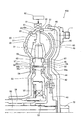
- FIG. 1 is a cross-sectional view of a torque converter according to a first embodiment of the present invention.
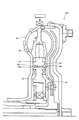
- FIG. 2 is a cross-sectional view of a torque converter according to a second embodiment of the present invention.
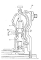
- FIG. 3 is a cross-sectional view of a torque converter according to a third embodiment of the present invention.
- FIG. 4 is a cross-sectional view of a torque converter according to a fourth embodiment of the present invention.
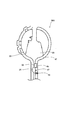
- FIG. 5 is a cross-sectional view of a fluid coupling according to a fifth embodiment of the present invention.
- the first embodiment will be described.
- FIG. 1 is a cross-sectional view of a torque converter 100 according to a first embodiment of the present invention.
- the torque converter 100 includes a front cover 10 and an impeller shell 20 defining a fluid chamber 60 therein, a pump impeller 30 housed in the front cover 10 and the impeller shell 20, a turbine runner 40, and a stator 50. Be done.
- the front cover 10 is fitted to the open end 21 of the impeller shell 20 so as to be integrally rotatable with the impeller shell 20, and is connected to a drive source such as an engine via the boss 11.
- the impeller shell 20 is fitted to the front cover 10 to define a fluid chamber 60.
- a pump impeller 30 is disposed on the inner wall of the impeller shell 20.
- a permanent magnet 22 is disposed on the inner surface of the impeller shell 20 and closer to the front cover 10 than the pump impeller 30 in the circumferential direction.
- the pump impeller 30 is disposed on the inner wall on the outer diameter side of the impeller shell 20, and is constituted by a plurality of vanes 31 disposed at predetermined intervals in the circumferential direction.
- the pump impeller 30 rotates integrally with the impeller shell 20 to flow the working fluid from the inner circumferential side to the outer circumferential side along the flow path.
- the turbine runner 40 is configured of a turbine hub 41, a turbine shell 42, and blades 43.
- the turbine hub 41 is connected to the output shaft 80.
- the turbine shell 42 is connected to the outer peripheral side of the turbine hub 41 and disposed between the pump impeller 30 and the front cover 10.
- a large number of blades 43 are disposed at predetermined intervals in the circumferential direction so as to face the pump impeller 30 on the pump impeller 30 side of the turbine shell 42.
- a hub plate 44 disposed at a predetermined distance from the turbine shell 42 along the turbine shell 42 is connected to an outer peripheral side of the turbine hub 41.
- the outer peripheral end of the hub plate 44 is extended to the vicinity of the inner wall of the impeller shell 20.
- a gap 61 is formed such that the turbine shell 42 and the impeller shell 20 do not interfere with each other when the turbine runner 40 rotates.
- the turbine runner 40 rotates as the working fluid flowing from the pump impeller 30 flows from the outer peripheral side to the inner peripheral side along the flow path, and transmits the driving force to the output shaft 80.
- the stator 50 is provided between the pump impeller 30 and the turbine runner 40 so as to be adjacent to the inner peripheral side of the pump impeller 30 and the inner peripheral side of the turbine runner 40, and a number of stators 50 are arranged circumferentially at predetermined intervals. It is comprised by the blade 51.
- the stator 50 is connected to a stator shaft 59, which is a fixed shaft, via the one-way clutch 52 and the inner circumferential support portion 53, and rotates in only one direction.
- a thrust bearing 54 is interposed between the stator 50 and the impeller shell 20 and between the stator 50 and the turbine shell 42, and the stator 50 is axially supported.
- a gap 62 between the stator 50 and the impeller shell 20 and a gap 63 between the stator 50 and the turbine shell 42 are formed on the inner peripheral side of the blades 51 of the stator 50 and on the outer peripheral side of the thrust bearing 54.
- the clearances 62 and 63 are set so as not to interfere with each other when the stator 50 and the turbine runner 40 rotate.
- permanent magnets 55 are disposed at positions adjacent to the gaps 62, 63, respectively.
- a plurality of stator penetration passages 56 axially penetrating the stator 50 are provided at predetermined intervals in the circumferential direction on the inner circumferential side of the permanent magnet 55 of the stator 50 and on the outer circumferential side of the thrust bearing 54.
- a plurality of turbine through passages 45 axially penetrating through the turbine shell 42 are provided at predetermined intervals in the circumferential direction on the turbine shell 42 at positions corresponding to the turbine side openings 56 a of the stator through passages 56.
- the turbine through passage 45 is formed so as to expand in diameter on the outer peripheral side of the stator through passage 56.
- the torque converter 100 is configured as described above, and the pump impeller 30, the turbine runner 40, and the stator 50 define a torus 64 which is a flow path of the working fluid.
- the torus 64 is filled with a magnetic fluid 65 having a specific gravity greater than that of ATF as a working fluid.
- the magnetic fluid 65 is a fluid having magnetism by mixing iron powder or the like as magnetic particles.
- magnetic fluid refers to various types of fluids, such as magnetorheological fluids, that differ in the size of the magnetic particles.
- the magnetic fluid 65 is filled only in the torus 64, and a portion other than the torus 64 inside the front cover 10 and the impeller shell 20 is filled with lubricating oil (ATF). That is, in the torque converter 100 of the present embodiment, the magnetic fluid 65 is used as a working fluid, and the ATF is used as a lubricating oil.
- ATF lubricating oil
- the magnetic field acts on the gap 61 between the outer peripheral end 42a of the turbine shell 42 and the impeller shell 20 and the gaps 62 and 63 between the stator 50 and the impeller shell 20 and the turbine shell 42 by the permanent magnets 22 and 55.
- the shear force of the magnetic fluid 65 in 61, 62, 63 changes to increase the viscosity. This can prevent the magnetic fluid 65 from leaking from the torus 64 to the ATF side.
- a controller 92 is provided on the outside of the front cover 10 and the impeller shell 20 to control the amount of energization of the electromagnet 91 and the electromagnet 91.
- the controller 92 changes the amount of energization of the electromagnet 91 to change the shear force of the magnetic fluid 65 in the torus 64.
- the torque capacity of the torque converter 100 can be changed according to the traveling state of the vehicle, and furthermore, control can be performed in a lockup state in which no slip occurs between the pump impeller 30 and the turbine runner 40.
- the internal pressure of the magnetic fluid 65 having a large specific gravity may increase, and the magnetic fluid 65 may gradually leak from the gap between the stator 50 and the impeller shell 20 and the turbine shell 42.
- a second recess 58 opening at 63 is provided.
- a third recess 23 opening in the gap 62 with the stator 50 is provided on the impeller shell 20 facing the first recess 57.
- the inner surfaces of the first recess 57, the second recess 58, and the third recess 23 are all formed to have a curved shape.
- the magnetic fluid 65 leaking from the gaps 62 and 63 is temporarily stored in the first recess 57, the second recess 58, and the third recess 23, and is generated by the centrifugal force generated by the rotation of the torque converter 100. It can be returned to the torus 64. Furthermore, since the inner surface of each recess 57, 58, 23 is formed to have a curved shape, the magnetic fluid 65 can be smoothly moved along the inner surface to each gap 62, 63 by centrifugal force. The magnetic fluid 65 returned to each gap 62, 63 is returned into the torus 64 by centrifugal force.
- the magnetic fluid 65 is agitated in the torus 64 by the use of the torque converter 100, particularly in the torque converter region, so that the temperature of the magnetic fluid 65 rises.
- the magnetic fluid 65 is degraded as the temperature becomes high, and the change in viscosity with respect to the change in magnetic field is reduced. Since the slip generated between the pump impeller 30 and the turbine runner 40 changes in accordance with the viscosity of the magnetic fluid 65, deterioration of the magnetic fluid 65 makes it difficult to maintain the torque converter 100 in a lockup state.
- the permanent magnets 22 and 55 provided to hold the magnetic fluid 65 in the torus 64 are demagnetized when the temperature becomes high, and the magnetic force does not recover even if the temperature is returned to normal temperature. This may cause the magnetic fluid 65 to leak out of the torus 64.
- permanent magnets 22 and 55 and magnetic fluid 65 are cooled by circulating ATF.
- the ATF flows from the inner circumferential side to the outer circumferential side of the stator 50 to lubricate the one-way clutch 52 and the thrust bearing 54, and flows in the stator through passage 56. After absorbing the heat of the permanent magnet 55 in the stator through passage 56, the heat flows through the turbine through passage 45 to the flow passage between the turbine shell 42 and the hub plate 44.
- the ATF flows to the outer peripheral side along the turbine shell 42 to absorb the heat of the magnetic fluid 65 in the torus 64 and to absorb the heat of the permanent magnet 22 at the outer peripheral end 42 a of the turbine shell 42. Thereafter, the ATF flows in the flow path between the hub plate 44 and the front cover 10 to the inner peripheral side, is subjected to lubrication of the output shaft 80, and then flows from the inner peripheral side to the outer peripheral side of the stator 50 again. Do.
- the impeller shell side opening 56b of the stator through passage 56 is formed with an inner peripheral side enlarged diameter portion 56c which is gradually expanded in diameter toward the opening end.
- the magnetic fluid 65 is filled only in the torus 64, and the gap 61 between the turbine shell 42 and the impeller shell 20, the gap 62 between the stator 50 and the impeller shell 20, the turbine shell 42 and the stator Since the magnetic field is applied to the gap 63 with 50, the viscosity of the magnetic fluid 65 can be increased in each of the gaps 61, 62, 63 to prevent the magnetic fluid 65 from leaking. As a result, since it is sufficient to fill the magnetic fluid 65 only in the torus 64 which is a fluid chamber necessary for power transmission from the input side to the output side, the amount of the magnetic fluid 65 necessary for the torque converter 100 is reduced to reduce cost. Can be reduced.
- the permanent magnets 22 and 55 that cause the magnetic fluid 65 to exert a magnetic field are cooled by flowing the ATF, it is possible to prevent the permanent magnets 22 and 55 from demagnetizing due to high temperature. Thereby, the magnetic force can be reduced to prevent the magnetic fluid 65 from leaking to the outside of the torus 64.
- stator 50 is provided with the stator through passage 56 axially penetrating the stator 50, and the ATF is allowed to flow through the stator through passage 56, the permanent magnet 55 disposed in the stator 50 can be cooled. Can prevent the magnetic fluid 65 from leaking out.
- a first recess 57 and a second recess 58 are provided on the gaps 62 and 63 between the stator 50 and the impeller shell 20 and the turbine shell 42. Since the third recess 23 is provided, magnetic particles contained in the magnetic fluid 65 leaking from the gaps 61, 62, 63 can be stored. Thereby, the magnetic particles in the magnetic fluid 65 can be prevented from leaking, so that the density of the magnetic fluid 65 can be reduced, and the magnetic fluid 65 can be prevented from leaking to the outside of the torus 64.
- the processability of each recess 23, 57, 58 at the time of manufacturing the torque converter 100 can be improved.
- the magnetic fluid 65 can be smoothly moved along the inner surface to the gaps 62, 63 by the centrifugal force, and the magnetic fluid 65 returned to the gaps 62, 63 is further transferred into the torus 64 by the centrifugal force. It can be reliably returned.
- impeller shell side opening 56b of the stator through passage 56 is formed with the inner peripheral side enlarged diameter portion 56c which is gradually diameter-expanded toward the opening end toward the opening end.
- the contamination in the ATF blocks the recesses 57, 58, 23, and the magnetic fluid 65 leaked from the gaps 62, 63 flows into the transmission together with the ATF without being stored in the recesses 57, 58, 23. Can be prevented. As a result, it is possible to prevent the magnetic fluid 65 from becoming contamination in the transmission and causing a valve stick or the like.
- the turbine through passage 45 axially penetrating the turbine shell 42 is provided at a position of the turbine shell 42 corresponding to the turbine side opening 56 a of the stator through passage 56, the ATF flowing through the stator through passage 56 is A flow path between the turbine shell 42 and the front cover 10 can be supplied via the turbine through passage 45. Thereby, the magnetic fluid 65 in the torus 64 can be cooled via the turbine shell 42, and the deterioration of the magnetic fluid 65 can be prevented.
- the turbine through passage 45 is formed by expanding the diameter of the stator through passage 56 on the outer peripheral side of the turbine shell 42, the flow of ATF flowing from the stator through passage 56 through the turbine through passage 45 is further smoothened. Thus, the lubricating performance of the torque converter 100 can be improved.
- the hub plate 44 is disposed along the turbine shell 42 at a predetermined distance from the turbine shell 42 and the outer peripheral end of the hub plate 44 extends to the vicinity of the inner wall of the impeller shell 20
- the magnetic fluid 65 in the torus 64 can be cooled, and the permanent magnet 22 disposed on the inner wall of the impeller shell 20 can be cooled.
- deterioration of the magnetic fluid 65 and the permanent magnet 22 can be prevented, and deterioration and leakage of the magnetic fluid can be prevented.
- FIG. 2 is a cross-sectional view of a torque converter 200 according to a second embodiment of the present invention.
- the impeller shell side opening 56 b and the turbine side opening 56 a of the stator through passage 56 are gradually moved toward the opening end.
- outer peripheral side enlarged diameter portions 56d and 56e which are expanded in diameter toward the outer peripheral side.
- the centrifugal force is applied to the magnetic particles of the magnetic fluid 65 that leaks from the gaps 62 and 63 between the stator 50 and the impeller shell 20 and the turbine shell 42 to the inner peripheral side.
- the magnetic particles can be returned to the outer peripheral side along the outer peripheral side enlarged diameter portions 56d, 56e.
- FIG. 3 is a cross-sectional view of a torque converter 300 according to a third embodiment of the present invention.
- the impeller shell side opening 56b of the stator through passage 56 is provided with an outer peripheral side enlarged diameter portion 56f gradually diametered outward toward the opening end.
- the inner surface shapes of the first recess 57 and the second recess 58 are formed to have inclined surfaces 57a and 58a in which the recess is deepened toward the inner peripheral side instead of the curved surface.
- the magnetic fluid 65 that has leaked to the inner circumferential side after passing through the first recess 57 and the third recess 23 can be pulled back to the torus 64 by centrifugal force, and the magnetic particles exert centrifugal force. At the time, the magnetic particles can be pulled back to the outer peripheral side of the stator 50 along the outer peripheral side enlarged diameter portion 56f.
- the inner surfaces of the first recess 57 and the second recess 58 have the inclined surfaces 57a and 58a, when centrifugal force is applied to the magnetic particles, the magnetic particles are taken along the outer surfaces of the stator 50 along the inclined surfaces 57a and 58a. It can be pulled back to the side.
- FIG. 4 is a cross-sectional view of a torque converter 400 according to a fourth embodiment of the present invention.
- the third recess 23 in the first embodiment is not a curved surface, but has a constant axial depth of the recess over the radial direction of the impeller shell 20.
- the magnetic particles of the magnetic fluid 65 leaking from the clearances 62 and 63 between the stator 50 and the impeller shell 20 and the turbine shell 42 to the inner peripheral side can be captured more reliably to restrict the movement to the inner peripheral side.
- FIG. 5 is a cross-sectional view of a fluid coupling 500 according to a fifth embodiment of the present invention. In FIG. 5, only a portion where the pump impeller 30 and the turbine runner 40 face each other is shown.
- the present embodiment is a fluid coupling 500 which does not include the stator 50.
- a permanent magnet 46 is disposed on the turbine shell 42 facing the gap 66 between the impeller shell 20 and the turbine shell 42.
- the recess 47 corresponding to the first recess 57 of the first embodiment is provided on the turbine shell 42 on the inner peripheral side of the permanent magnet 46.
- the recess 24 corresponding to the third recess 23 of the first embodiment is provided on the impeller shell 20 on the inner peripheral side of the permanent magnet 46.
- a turbine through passage 48 axially penetrating the turbine shell 42 is provided on the inner peripheral side of the recess 47 of the turbine shell 42.
- the magnetic particles of the magnetic fluid 65 leaking from the gap between the impeller shell 20 and the turbine shell 42 are formed in the recesses 24 and 47 as in the first embodiment. It can be stored. Furthermore, by causing the ATF to flow from the turbine through passage 48 to the opposite side of the turbine shell 42, the permanent magnet 46 can be cooled to prevent the leakage of the magnetic fluid 65 due to the demagnetization.
- the combination of the inner surface shape and arrangement of the first recess 57, the second recess 58, and the third recess 23 is not limited to the examples shown in the first to fifth embodiments, and other shapes may be used. And arrangement.
- the ATF is circulated to cool the magnetic fluid 65 and the permanent magnets 22 and 55.
- another fluid exhibiting a lubricating function may be used instead of the ATF. .
Landscapes
- Engineering & Computer Science (AREA)
- General Engineering & Computer Science (AREA)
- Mechanical Engineering (AREA)
- Control Of Fluid Gearings (AREA)
Abstract
流体継手は、駆動源の駆動力が入力されるインペラと、インペラと対向して配置され、流体継手の出力軸に動力を伝達するタービンと、インペラとタービンとによって画成されるトーラス内に作動流体として充填され、磁界を作用させることで粘性が変化する磁性流体と、トーラスの外周端側に形成されるタービンとインペラとの隙間である外周側隙間、及びトーラスの内周端側に形成されるタービンとインペラとの隙間である内周側隙間において、磁性流体に磁界を作用させる磁界発生部とを備える。
Description
本発明は、流体継手に関する。
流体継手は、入力軸に連結されるインペラと、出力軸に連結されるタービンと、インペラ及びタービンの間に充填される作動油とを備え、入力軸のトルクをインペラから作動油を介してタービンへと伝達する。
JP7-2663Uには、流体継手に充填する作動油として、ATFより比重の大きい磁性流体を使用することで流体継手の性能を向上させ、流体継手を小型化することが記載されている。
しかし、上記従来の技術では、流体継手内全体に磁性流体が充填されるので、必要な磁性流体の量が多くなる。磁性流体はATFより高価であるので、流体継手全体のコストが上昇する。
本発明は、このような技術的課題に鑑みてなされたものであり、流体継手に必要な磁性流体の量を低減してコストを低減することを目的とする。
本発明のある態様によれば、流体継手であって、駆動源の駆動力が入力されるインペラと、インペラと対向して配置され、流体継手の出力軸に動力を伝達するタービンと、インペラとタービンとによって画成されるトーラス内に作動流体として充填され、磁界を作用させることで粘性が変化する磁性流体と、トーラスの外周端側に形成されるタービンとインペラとの隙間である外周側隙間、及びトーラスの内周端側に形成されるタービンとインペラとの隙間である内周側隙間において、磁性流体に磁界を作用させる磁界発生部と、を備える流体継手が提供される。
上記態様によれば、磁性流体を作動流体としてトーラス内に充填し、トーラスの内周側及び外周側の隙間に磁界を作用させるので、当該隙間における磁性流体の粘度を上昇させて磁性流体がトーラスから漏出することを防止することができる。これにより、必要な磁性流体の量を減らすことができるので、コストを低減することができる。
以下、添付図面を参照しながら本発明の実施形態について説明する。
第1実施形態について説明する。
図1は本発明の第1実施形態に係るトルクコンバータ100の断面図である。トルクコンバータ100は、内部に流体室60を画成するフロントカバー10及びインペラシェル20と、フロントカバー10及びインペラシェル20内に収容されるポンプインペラ30、タービンランナ40、及びステータ50と、から構成される。
フロントカバー10は、インペラシェル20と一体的に回転可能なようにインペラシェル20の開口端21に嵌合され、ボス11を介してエンジン等の駆動源に接続される。
インペラシェル20は、フロントカバー10に嵌合されて流体室60を画成する。インペラシェル20の内壁にはポンプインペラ30が配設される。インペラシェル20の内壁であってポンプインペラ30よりフロントカバー10側には永久磁石22が周方向にわたって配設される。
ポンプインペラ30は、インペラシェル20の外径側の内壁に配置され、周方向に所定の間隔で多数配置される羽根31によって構成される。ポンプインペラ30は、インペラシェル20と一体的に回転して作動流体を流路に沿って内周側から外周側へと流動させる。
タービンランナ40は、タービンハブ41と、タービンシェル42と、羽根43とによって構成される。タービンハブ41はアウトプットシャフト80に連結される。タービンシェル42は、タービンハブ41の外周側に連結され、ポンプインペラ30とフロントカバー10との間に配置される。羽根43は、タービンシェル42のポンプインペラ30側においてポンプインペラ30に対向するように周方向に所定の間隔で多数配置される。
タービンハブ41の外周側には、タービンシェル42に沿ってタービンシェル42から所定の間隔をおいて配置されるハブプレート44が連結される。ハブプレート44の外周端はインペラシェル20の内壁近傍まで延設される。
タービンシェル42の外周端42aとインペラシェル20の内壁に設けられる永久磁石22との間には、タービンランナ40の回転時にタービンシェル42とインペラシェル20とが干渉しない程度の隙間61が形成される。タービンランナ40は、ポンプインペラ30から流動する作動流体が流路に沿って外周側から内周側へと流動することで回転し、アウトプットシャフト80に駆動力を伝達する。
ステータ50は、ポンプインペラ30とタービンランナ40との間において、ポンプインペラ30の内周側とタービンランナ40の内周側とに隣接するように設けられ、周方向に所定の間隔で多数配置される羽根51によって構成される。
ステータ50は、ワンウェイクラッチ52及び内周支持部53を介して固定軸であるステータシャフト59に連結され、一方向にのみ回転する。ステータ50とインペラシェル20との間及びステータ50とタービンシェル42との間には、スラストベアリング54が介装され、ステータ50が軸方向に支持される。
ステータ50の羽根51より内周側でスラストベアリング54より外周側には、ステータ50とインペラシェル20との隙間62及びステータ50とタービンシェル42との隙間63が形成される。当該隙間62、63は、ステータ50及びタービンランナ40の回転時に、互いに干渉しない程度に設定される。ステータ50には、隙間62、63に隣接する位置にそれぞれ永久磁石55が配設される。
ステータ50の永久磁石55より内周側でスラストベアリング54より外周側には、ステータ50を軸方向に貫通するステータ貫通路56が周方向に所定の間隔で複数設けられる。タービンシェル42上であって、ステータ貫通路56のタービン側開口部56aに対応する位置には、タービンシェル42を軸方向に貫通するタービン貫通路45が周方向に所定の間隔で複数設けられる。タービン貫通路45は、ステータ貫通路56より外周側に拡径して形成される。
トルクコンバータ100は上記のように構成され、ポンプインペラ30、タービンランナ40、及びステータ50によって作動流体の流路であるトーラス64を画成する。トーラス64内には、作動流体としてATFより比重の大きい磁性流体65が充填される。磁性流体65は、磁性粒子として鉄粉等を混入し磁性を帯びた流体である。本明細書では、「磁性流体」は、磁気粘性流体など、磁性粒子の径が異なる様々な種類の流体を指す。
磁性流体65はトーラス64内にのみ充填され、フロントカバー10及びインペラシェル20の内部であってトーラス64以外の部分には潤滑油(ATF)が充填される。すなわち、本実施形態のトルクコンバータ100において磁性流体65は作動流体として用いられ、ATFは潤滑油として用いられる。
タービンシェル42の外周端42aとインペラシェル20との隙間61、並びにステータ50とインペラシェル20及びタービンシェル42との隙間62、63には、永久磁石22、55によって磁界が作用するので、各隙間61、62、63内の磁性流体65のせん断力が変化して粘性が高くなる。これにより、トーラス64からATF側へと磁性流体65が漏出することを防止することができる。
フロントカバー10及びインペラシェル20の外側には電磁石91及び電磁石91の通電量を制御するコントローラ92が設けられる。コントローラ92は、電磁石91の通電量を変化させてトーラス64内の磁性流体65のせん断力を変化させる。これにより、車両の走行状態に応じてトルクコンバータ100のトルク容量を変化させることができ、さらに、ポンプインペラ30とタービンランナ40との間にスリップが生じないロックアップ状態に制御することもできる。
トルクコンバータ100が回転すると、比重の大きな磁性流体65の内圧が上昇して磁性流体65がステータ50とインペラシェル20及びタービンシェル42との隙間から徐々に漏出する可能性がある。
そこで、本実施形態では、ステータ50の永久磁石55より内周側でステータ貫通路56より外周側に、インペラシェル20との隙間62に開口する第1の凹部57と、タービンシェル42との隙間63に開口する第2の凹部58とが設けられる。さらに、第1の凹部57に対向するインペラシェル20上には、ステータ50との隙間62に開口する第3の凹部23が設けられる。第1の凹部57、第2の凹部58、及び第3の凹部23の内面は、いずれも曲面形状となるように形成される。
これにより、隙間62、63から漏出する磁性流体65は第1の凹部57、第2の凹部58、及び第3の凹部23に一時的に貯留され、トルクコンバータ100の回転によって発生する遠心力によってトーラス64内へと戻すことができる。さらに、各凹部57、58、23の内面は曲面形状となるように形成されるので、遠心力によって磁性流体65を内面に沿ってスムーズに各隙間62、63へと移動させることができる。各隙間62、63に戻された磁性流体65は遠心力によりトーラス64内へと戻される。
また、トルクコンバータ100の特にトルクコンバータ領域での使用によって、磁性流体65はトーラス64内で攪拌されるので、磁性流体65の温度が上昇する。磁性流体65は高温になると劣化し、磁界の変化に対する粘度の変化が小さくなる。ポンプインペラ30とタービンランナ40との間に生じるスリップは、磁性流体65の粘度に応じて変化するので、磁性流体65が劣化するとトルクコンバータ100をロックアップ状態に維持することが難しくなる。
さらに、トーラス64内に磁性流体65を保持するために設けられる永久磁石22、55は高温になると減磁し、常温に戻しても磁力が回復しなくなる。これにより、磁性流体65がトーラス64の外部へと漏出する可能性がある。
そこで、本実施形態では、ATFを循環させることによって永久磁石22、55及び磁性流体65を冷却している。
ATFはステータ50の内周側から外周側へと流動してワンウェイクラッチ52及びスラストベアリング54を潤滑し、ステータ貫通路56内を流動する。ステータ貫通路56内で永久磁石55の熱を吸収した後、タービン貫通路45を通って、タービンシェル42とハブプレート44との間の流路へと流動する。
ATFはタービンシェル42に沿って外周側へと流動することでトーラス64内の磁性流体65の熱を吸収し、タービンシェル42の外周端42aにおいて永久磁石22の熱を吸収する。その後、ATFはハブプレート44とフロントカバー10との間の流路を内周側へと流動し、アウトプットシャフト80の潤滑に供された後、再度ステータ50の内周側から外周側へと流動する。
また、ステータ貫通路56のインペラシェル側開口部56bには、開口端へ向かって徐々に内周側へと拡径した内周側拡径部56cが形成される。これにより、ATFがステータ貫通路56へと流動する際に、ATF内のコンタミがステータ貫通路56の入口56bを閉塞することを防止することができる。
以上のように本実施形態では、トーラス64内にのみ磁性流体65を充填し、タービンシェル42とインペラシェル20との隙間61、ステータ50とインペラシェル20との隙間62、及びタービンシェル42とステータ50との隙間63に磁界を作用させるので、各隙間61、62、63において磁性流体65の粘性を上げて磁性流体65の漏出を防止することができる。これにより、入力側から出力側への動力伝達に必要な流体室であるトーラス64内にのみ磁性流体65を充填すれば足りるので、トルクコンバータ100に必要な磁性流体65の量を低減してコストを低減することができる。
また、磁性流体65に磁界を作用させる永久磁石22、55を、ATFを流動させることで冷却するので、永久磁石22、55が高温となって減磁することを防止することができる。これにより、磁力が低下して磁性流体65がトーラス64の外側へと漏出することを防止することができる。
さらに、ステータ50にはステータ50を軸方向に貫通するステータ貫通路56を設け、ATFをステータ貫通路56に流すので、ステータ50に配設される永久磁石55を冷却することができ、減磁による磁性流体65の漏出を防止することができる。
さらに、ステータ50とインペラシェル20及びタービンシェル42との隙間62、63上であって永久磁石55より内周側でステータ貫通路56より外周側に、第1の凹部57、第2の凹部58、及び第3の凹部23を設けるので、当該隙間61、62、63から漏出する磁性流体65に含まれる磁性粒子を貯留することができる。これにより、磁性流体65中の磁性粒子が漏出することを防止できるので、磁性流体65の密度が低下して、磁性流体65がトーラス64の外側へと漏出することを防止することができる。
さらに、第1の凹部57、第2の凹部58、及び第3の凹部23の内面は曲面形状であるので、トルクコンバータ100の製造時における各凹部23、57、58の加工性を向上させることができる。また、遠心力によって磁性流体65を内面に沿ってスムーズに各隙間62、63へと移動させることができ、各隙間62、63に戻された磁性流体65を遠心力によりトーラス64内へとより確実に戻すことができる。
さらに、ステータ貫通路56のインペラシェル側開口部56bには、開口端へ向かって徐々に内周側へと拡径した内周側拡径部56cが形成されるので、ATFがステータ貫通路56へと流動する際に、ATF内のコンタミがステータ貫通路56の入口を閉塞することを防止でき、ATFによるトルクコンバータ100の潤滑性能を保持することができる。
また、ATF内のコンタミが遠心力や永久磁石22、55、磁性流体65、電磁石91の磁力によってトーラス64内に入り込むことによる磁性流体65の特性変化を防止することができる。さらに、ATF内のコンタミが各凹部57、58、23を塞いでしまい、各隙間62、63から漏出した磁性流体65が各凹部57、58、23に貯留されずにATFとともに変速機内へ流れることを防止することができる。これにより、磁性流体65が変速機内でコンタミとなりバルブスティック等を引き起こすことを防止することができる。
さらに、タービンシェル42の、ステータ貫通路56のタービン側開口部56aに対応する位置には、タービンシェル42を軸方向に貫通するタービン貫通路45が設けられるので、ステータ貫通路56を流れるATFをタービン貫通路45を介してタービンシェル42とフロントカバー10との間の流路に供給することができる。これにより、タービンシェル42を介してトーラス64内の磁性流体65を冷却することができ、磁性流体65の劣化を防止することができる。
さらに、タービン貫通路45はステータ貫通路56よりタービンシェル42の外周側に拡径して形成されるので、ステータ貫通路56からタービン貫通路45を介して流れるATFの流れをより円滑化することができ、トルクコンバータ100の潤滑性能を向上させることができる。
さらに、ハブプレート44がタービンシェル42に沿ってタービンシェル42から所定の間隔をおいて配置され、ハブプレート44の外周端がインペラシェル20の内壁近傍まで延設されるので、タービン貫通路45を流れるATFをタービンシェル42に沿って流動させることでトーラス64内の磁性流体65を冷却するとともに、インペラシェル20の内壁に配設される永久磁石22を冷却することができる。これにより、磁性流体65及び永久磁石22の劣化を防止して、磁性流体の劣化及び漏出を防止することができる。
次に、第2実施形態について説明する。
図2は本発明の第2実施形態に係るトルクコンバータ200の断面図である。本実施形態では、第1実施形態における第1の凹部57及び第2の凹部58に代えて、ステータ貫通路56のインペラシェル側開口部56b及びタービン側開口部56aに、開口端へ向かって徐々に外周側へと拡径した外周側拡径部56d、56eを備えた。
これにより、第1実施形態の凹部57、58と同様に、ステータ50とインペラシェル20及びタービンシェル42との隙間62、63から内周側へと漏出した磁性流体65の磁性粒子に遠心力が作用した際に、磁性粒子を外周側拡径部56d、56eに沿って外周側へと戻すことができる。
次に、第3実施形態について説明する。
図3は本発明の第3実施形態に係るトルクコンバータ300の断面図である。本実施形態では、第1実施形態の構成に加えて、ステータ貫通路56のインペラシェル側開口部56bに、開口端へ向かって徐々に外周側へと拡径した外周側拡径部56fを備えた。また、第1の凹部57及び第2の凹部58の内面形状は、曲面に代えて内周側へ向けて窪みが深くなる傾斜面57a、58aを有する形状とした。
これにより、第1の凹部57及び第3の凹部23を通過して内周側へと漏出した磁性流体65を遠心力によってトーラス64側へと引き戻すことができるとともに、磁性粒子に遠心力が作用した際に磁性粒子を外周側拡径部56fに沿ってステータ50の外周側へと引き戻すことができる。
また、第1の凹部57及び第2の凹部58の内面が傾斜面57a、58aを有するので、磁性粒子に遠心力が作用した際に磁性粒子を傾斜面57a、58aに沿ってステータ50の外周側へと引き戻すことができる。
次に、第4実施形態について説明する。
図4は本発明の第4実施形態に係るトルクコンバータ400の断面図である。本実施形態では、第1実施形態における第3の凹部23を、曲面形状ではなく窪みの軸方向深さがインペラシェル20の径方向にわたって一定の形状とした。
これにより、ステータ50とインペラシェル20及びタービンシェル42との隙間62、63から内周側へと漏出した磁性流体65の磁性粒子をより確実に捕捉して内周側への移動を制限することができる。
次に、第5実施形態について説明する。
図5は本発明の第5実施形態に係るフルードカップリング500の断面図である。なお、図5ではポンプインペラ30とタービンランナ40とが対向する部分だけを示している。
本実施形態は、第1~第4実施形態と異なり、ステータ50を備えていないフルードカップリング500である。インペラシェル20とタービンシェル42との隙間66に面するタービンシェル42上には永久磁石46が配設される。第1実施形態の第1の凹部57に対応する凹部47は、永久磁石46より内周側のタービンシェル42上に設けられる。第1実施形態の第3の凹部23に対応する凹部24は、永久磁石46より内周側のインペラシェル20上に設けられる。タービンシェル42の凹部47より内周側には、タービンシェル42を軸方向に貫通するタービン貫通路48が設けられる。
これにより、ステータ50を有していないフルードカップリング500においても、第1実施形態と同様に、インペラシェル20とタービンシェル42との隙間から漏出する磁性流体65の磁性粒子を凹部24、47に貯留することができる。さらに、ATFをタービン貫通路48からタービンシェル42の反対側へと流動させることで、永久磁石46を冷却して減磁による磁性流体65の漏出を防止することができる。
以上、本発明の実施形態について説明したが、上記実施形態は本発明の適用例の一つを示したに過ぎず、本発明の技術的範囲を上記実施形態の具体的構成に限定する趣旨ではない。
例えば、第1の凹部57、第2の凹部58、及び第3の凹部23の内面形状及び配置の組み合わせは、第1~第5実施形態に示した例に限定されることなく、その他の形状及び配置であってもよい。
また、第1~第5実施形態では、磁性流体65及び永久磁石22、55の冷却のためATFを循環させているが、ATFに代えて潤滑機能を発揮するその他の流体を使用してもよい。
本願は2011年3月7日に日本国特許庁に出願された特願2011-48943に基づく優先権を主張し、この出願の全ての内容は参照により本明細書に組み込まれる。
Claims (19)
- 流体継手であって、
駆動源の駆動力が入力されるインペラと、
前記インペラと対向して配置され、前記流体継手の出力軸に動力を伝達するタービンと、
前記インペラと前記タービンとによって画成されるトーラス内に作動流体として充填され、磁界を作用させることで粘性が変化する磁性流体と、
前記トーラスの外周端側に形成される前記タービンと前記インペラとの隙間である外周側隙間、及び前記トーラスの内周端側に形成される前記タービンと前記インペラとの隙間である内周側隙間において、前記磁性流体に磁界を作用させる磁界発生手段と、
を備える流体継手。 - 請求項1に記載の流体継手であって、
前記磁界発生手段は、前記外周側隙間に隣接して配置される外周側磁石及び前記内周側隙間に隣接して配置される内周側磁石であり、
前記磁性流体、前記外周側磁石及び前記内周側磁石を冷却する冷却手段を備える流体継手。 - 請求項2に記載の流体継手であって、
前記インペラと前記タービンとの間に配置され、前記インペラ及び前記タービンとともに前記トーラスを画成するステータと、
前記ステータの前記トーラスより内周側であって前記内周側磁石より内周側に配置される、前記ステータを軸方向に貫通するステータ貫通路と、
を備え、
前記冷却手段は、前記ステータ貫通路を含む流体継手。 - 請求項3に記載の流体継手であって、
前記内周側磁石より内周側であって前記ステータ貫通路より外周側に配置され、前記トーラスから前記内周側隙間を通って漏出する前記磁性流体に含まれる磁性粒子を貯留する貯留手段を備える流体継手。 - 請求項4に記載の流体継手であって、
前記貯留手段は、前記内周側隙間に開口する凹部である流体継手。 - 請求項5に記載の流体継手であって、
前記凹部は、前記内周側隙間に面する前記インペラ上に設けられる流体継手。 - 請求項5に記載の流体継手であって、
前記凹部は、前記内周側隙間に面する前記ステータ上に設けられる流体継手。 - 請求項5に記載の流体継手であって、
前記凹部の内面は曲面形状である流体継手。 - 請求項4に記載の流体継手であって、
前記ステータ貫通路の前記インペラ側開口及び前記タービン側開口のうち少なくとも一方は、前記開口へ向かうほど前記ステータの外周側へ拡径した外周側拡径部を有し、
前記貯留手段は、前記外周側拡径部である流体継手。 - 請求項3に記載の流体継手であって、
前記ステータ貫通路の前記インペラ側開口は、前記開口へ向かうほど前記ステータの内周側へ拡径した内周側拡径部を有する流体継手。 - 請求項3に記載の流体継手であって、
前記ステータ貫通路に対して軸方向に対向する位置に配置され、前記タービンを軸方向に貫通するタービン貫通路を備え、
前記冷却手段は、前記タービン貫通路を含む流体継手。 - 請求項11に記載の流体継手であって、
前記タービン貫通路は、前記ステータ貫通路より前記タービンの外周側に拡径されている流体継手。 - 請求項11に記載の流体継手であって、
前記タービンに対して前記インペラとは反対側に配置され、前記タービン貫通路から前記タービンの外周側へと前記タービンに沿った流路を形成するハブプレートを備え、
前記冷却手段は、前記ハブプレートを含む流体継手。 - 請求項2に記載の流体継手であって、
前記流体継手はフルードカップリングであり、
前記タービンの前記トーラスより内周側であって前記内周側磁石より内周側に配置される、前記タービンを軸方向に貫通するタービン貫通路を備え、
前記冷却手段は、前記タービン貫通路を含む流体継手。 - 請求項14に記載の流体継手であって、
前記内周側磁石より内周側であって前記タービン貫通路より外周側に配置され、前記トーラスから前記内周側隙間を通って漏出する前記磁性流体に含まれる磁性粒子を貯留する貯留手段を備える流体継手。 - 請求項15に記載の流体継手であって、
前記貯留手段は、前記内周側隙間に開口する凹部である流体継手。 - 請求項16に記載の流体継手であって、
前記凹部は、前記内周側隙間に面する前記インペラ上に設けられる流体継手。 - 請求項16に記載の流体継手であって、
前記凹部は、前記内周側隙間に面する前記タービン上に設けられる流体継手。 - 請求項16に記載の流体継手であって、
前記凹部の内面は曲面形状である流体継手。
Priority Applications (1)
| Application Number | Priority Date | Filing Date | Title |
|---|---|---|---|
| JP2013503426A JP5619272B2 (ja) | 2011-03-07 | 2012-02-10 | 流体継手 |
Applications Claiming Priority (2)
| Application Number | Priority Date | Filing Date | Title |
|---|---|---|---|
| JP2011-048943 | 2011-03-07 | ||
| JP2011048943 | 2011-03-07 |
Publications (1)
| Publication Number | Publication Date |
|---|---|
| WO2012120966A1 true WO2012120966A1 (ja) | 2012-09-13 |
Family
ID=46797936
Family Applications (1)
| Application Number | Title | Priority Date | Filing Date |
|---|---|---|---|
| PCT/JP2012/053068 Ceased WO2012120966A1 (ja) | 2011-03-07 | 2012-02-10 | 流体継手 |
Country Status (2)
| Country | Link |
|---|---|
| JP (1) | JP5619272B2 (ja) |
| WO (1) | WO2012120966A1 (ja) |
Citations (7)
| Publication number | Priority date | Publication date | Assignee | Title |
|---|---|---|---|---|
| JPH01148160U (ja) * | 1988-03-31 | 1989-10-13 | ||
| JPH0242242A (ja) * | 1988-08-01 | 1990-02-13 | Minoru Kitamura | 流体変速機 |
| JPH072663U (ja) * | 1993-06-18 | 1995-01-13 | 達 加賀谷 | 磁性流体を使用したトルクコンバータ |
| JPH08261305A (ja) * | 1995-03-16 | 1996-10-11 | Fichtel & Sachs Ag | 流体トルクコンバータ |
| JPH10148249A (ja) * | 1996-11-19 | 1998-06-02 | Exedy Corp | トルクコンバータ |
| DE102006028776A1 (de) * | 2006-06-23 | 2007-12-27 | Daimlerchrysler Ag | Hydrodynamischer Drehmomentwandler für ein Kraftfahrzeug |
| DE102007030443A1 (de) * | 2007-06-29 | 2009-01-08 | Zf Friedrichshafen Ag | Hydrodynamischer Drehmomentwandler |
-
2012
- 2012-02-10 JP JP2013503426A patent/JP5619272B2/ja not_active Expired - Fee Related
- 2012-02-10 WO PCT/JP2012/053068 patent/WO2012120966A1/ja not_active Ceased
Patent Citations (7)
| Publication number | Priority date | Publication date | Assignee | Title |
|---|---|---|---|---|
| JPH01148160U (ja) * | 1988-03-31 | 1989-10-13 | ||
| JPH0242242A (ja) * | 1988-08-01 | 1990-02-13 | Minoru Kitamura | 流体変速機 |
| JPH072663U (ja) * | 1993-06-18 | 1995-01-13 | 達 加賀谷 | 磁性流体を使用したトルクコンバータ |
| JPH08261305A (ja) * | 1995-03-16 | 1996-10-11 | Fichtel & Sachs Ag | 流体トルクコンバータ |
| JPH10148249A (ja) * | 1996-11-19 | 1998-06-02 | Exedy Corp | トルクコンバータ |
| DE102006028776A1 (de) * | 2006-06-23 | 2007-12-27 | Daimlerchrysler Ag | Hydrodynamischer Drehmomentwandler für ein Kraftfahrzeug |
| DE102007030443A1 (de) * | 2007-06-29 | 2009-01-08 | Zf Friedrichshafen Ag | Hydrodynamischer Drehmomentwandler |
Also Published As
| Publication number | Publication date |
|---|---|
| JP5619272B2 (ja) | 2014-11-05 |
| JPWO2012120966A1 (ja) | 2014-07-17 |
Similar Documents
| Publication | Publication Date | Title |
|---|---|---|
| JP6137218B2 (ja) | 回転電機の冷却構造 | |
| KR102334032B1 (ko) | 원심 압축기 | |
| US9421854B2 (en) | Vehicle drive device | |
| US9249838B2 (en) | Transmission clutch with improved cooling | |
| JP5075872B2 (ja) | 電動機 | |
| WO2011062265A1 (ja) | 車両用駆動装置 | |
| JP2014047922A (ja) | トルクコンバータの油圧制御回路 | |
| JP5082106B2 (ja) | 高速フライホイールシール | |
| JP6967994B2 (ja) | 潤滑油供給装置 | |
| JP5565093B2 (ja) | 駆動力伝達装置 | |
| JP2020056321A (ja) | 遠心圧縮機 | |
| JP5686761B2 (ja) | 磁気粘性流体を用いたトルクコンバータ | |
| JP2012229719A (ja) | ロックアップクラッチ付きトルクコンバータ | |
| KR101509458B1 (ko) | 토크 컨버터 | |
| JP5310783B2 (ja) | 動力伝達装置 | |
| WO2012120966A1 (ja) | 流体継手 | |
| JP4447410B2 (ja) | 電動車両用モータのロータ冷却装置 | |
| CN105189225A (zh) | 带有空转泵的减速器 | |
| CN111971497B (zh) | 密封装置、液力机械和车辆 | |
| JP4944459B2 (ja) | 流体伝動装置のロックアップクラッチ | |
| JP3955874B2 (ja) | 原動機 | |
| JP5261461B2 (ja) | 車両用駆動装置 | |
| JP2012016240A (ja) | 回転電機及び回転電機冷却システム | |
| JP2013122219A (ja) | ウォータポンプ | |
| US20080217867A1 (en) | Sealing Structure of Casing |
Legal Events
| Date | Code | Title | Description |
|---|---|---|---|
| 121 | Ep: the epo has been informed by wipo that ep was designated in this application |
Ref document number: 12755759 Country of ref document: EP Kind code of ref document: A1 |
|
| ENP | Entry into the national phase |
Ref document number: 2013503426 Country of ref document: JP Kind code of ref document: A |
|
| NENP | Non-entry into the national phase |
Ref country code: DE |
|
| 122 | Ep: pct application non-entry in european phase |
Ref document number: 12755759 Country of ref document: EP Kind code of ref document: A1 |