WO2012117927A1 - 硫酸電解方法および硫酸電解装置 - Google Patents
硫酸電解方法および硫酸電解装置 Download PDFInfo
- Publication number
- WO2012117927A1 WO2012117927A1 PCT/JP2012/054371 JP2012054371W WO2012117927A1 WO 2012117927 A1 WO2012117927 A1 WO 2012117927A1 JP 2012054371 W JP2012054371 W JP 2012054371W WO 2012117927 A1 WO2012117927 A1 WO 2012117927A1
- Authority
- WO
- WIPO (PCT)
- Prior art keywords
- sulfuric acid
- electrolysis
- acid solution
- anode
- cathode
- Prior art date
- Legal status (The legal status is an assumption and is not a legal conclusion. Google has not performed a legal analysis and makes no representation as to the accuracy of the status listed.)
- Ceased
Links
Images



Classifications
-
- C—CHEMISTRY; METALLURGY
- C25—ELECTROLYTIC OR ELECTROPHORETIC PROCESSES; APPARATUS THEREFOR
- C25B—ELECTROLYTIC OR ELECTROPHORETIC PROCESSES FOR THE PRODUCTION OF COMPOUNDS OR NON-METALS; APPARATUS THEREFOR
- C25B1/00—Electrolytic production of inorganic compounds or non-metals
- C25B1/01—Products
- C25B1/28—Per-compounds
- C25B1/30—Peroxides
-
- C—CHEMISTRY; METALLURGY
- C25—ELECTROLYTIC OR ELECTROPHORETIC PROCESSES; APPARATUS THEREFOR
- C25B—ELECTROLYTIC OR ELECTROPHORETIC PROCESSES FOR THE PRODUCTION OF COMPOUNDS OR NON-METALS; APPARATUS THEREFOR
- C25B1/00—Electrolytic production of inorganic compounds or non-metals
- C25B1/01—Products
- C25B1/28—Per-compounds
- C25B1/29—Persulfates
-
- C—CHEMISTRY; METALLURGY
- C25—ELECTROLYTIC OR ELECTROPHORETIC PROCESSES; APPARATUS THEREFOR
- C25B—ELECTROLYTIC OR ELECTROPHORETIC PROCESSES FOR THE PRODUCTION OF COMPOUNDS OR NON-METALS; APPARATUS THEREFOR
- C25B11/00—Electrodes; Manufacture thereof not otherwise provided for
- C25B11/04—Electrodes; Manufacture thereof not otherwise provided for characterised by the material
- C25B11/042—Electrodes formed of a single material
- C25B11/043—Carbon, e.g. diamond or graphene
-
- C—CHEMISTRY; METALLURGY
- C25—ELECTROLYTIC OR ELECTROPHORETIC PROCESSES; APPARATUS THEREFOR
- C25B—ELECTROLYTIC OR ELECTROPHORETIC PROCESSES FOR THE PRODUCTION OF COMPOUNDS OR NON-METALS; APPARATUS THEREFOR
- C25B15/00—Operating or servicing cells
- C25B15/02—Process control or regulation
-
- C—CHEMISTRY; METALLURGY
- C25—ELECTROLYTIC OR ELECTROPHORETIC PROCESSES; APPARATUS THEREFOR
- C25B—ELECTROLYTIC OR ELECTROPHORETIC PROCESSES FOR THE PRODUCTION OF COMPOUNDS OR NON-METALS; APPARATUS THEREFOR
- C25B9/00—Cells or assemblies of cells; Constructional parts of cells; Assemblies of constructional parts, e.g. electrode-diaphragm assemblies; Process-related cell features
- C25B9/17—Cells comprising dimensionally-stable non-movable electrodes; Assemblies of constructional parts thereof
-
- H—ELECTRICITY
- H10—SEMICONDUCTOR DEVICES; ELECTRIC SOLID-STATE DEVICES NOT OTHERWISE PROVIDED FOR
- H10P—GENERIC PROCESSES OR APPARATUS FOR THE MANUFACTURE OR TREATMENT OF DEVICES COVERED BY CLASS H10
- H10P50/00—Etching of wafers, substrates or parts of devices
- H10P50/20—Dry etching; Plasma etching; Reactive-ion etching
- H10P50/28—Dry etching; Plasma etching; Reactive-ion etching of insulating materials
- H10P50/286—Dry etching; Plasma etching; Reactive-ion etching of insulating materials of organic materials
- H10P50/287—Dry etching; Plasma etching; Reactive-ion etching of insulating materials of organic materials by chemical means
Definitions
- the present invention relates to an electrolysis method and an electrolysis apparatus for producing persulfuric acid by electrolyzing sulfuric acid.
- a method in which a sulfuric acid solution is electrolyzed to produce peroxydisulfuric acid and peroxymonosulfuric acid (hereinafter collectively referred to as persulfuric acid) and used for cleaning semiconductor materials.
- a sulfuric acid solution is passed between the electrodes in the electrolytic cell, and a direct current voltage is applied between the anode and the cathode of the electrodes to perform electrolysis.
- a monopolar cell a pair of anode and cathode
- a bipolar cell using a bipolar electrode but the relationship between the pair of anode and cathode is the same.
- a spacer is usually used, and a sealing member such as an O-ring is used to seal the electrolytic solution.
- a sealing member such as an O-ring
- the inventor of the present application has proposed an electrolytic cell having such a structure (see Patent Document 1).
- FIG. A spacer 22 is disposed between the anode 20 and the cathode 21 to secure the flow path 23.
- the spacer 22 is formed with a liquid inlet hole 22 a on the inlet side and a liquid outlet hole 22 b on the outlet side.
- the liquid inlet hole 22 a and the liquid outlet hole 22 b are considerably narrower than the flow path 23. It consists of roads.
- an O-ring 24 is disposed as a sealing member between the spacer 22 and the electrode, and the sealing performance of the flow path 23 is ensured.
- FIG. 7B shows how sulfur accumulates in the vicinity of the O-ring part and the liquid discharge hole. It is presumed that sulfur is deposited as shown in A in the figure, and finally the precipitate is separated and moved, and eventually the cell outlet and the cell inlet are closed as shown in B in the figure.
- an object of the present invention is to provide an electrolysis method and an electrolysis apparatus that prevent accumulation of sulfur precipitated due to electrolysis of a sulfuric acid solution, and prevent clogging of the system due to sulfur precipitates.
- the first aspect of the present invention is the electrolysis cell in which at least the liquid contact surface is made of conductive diamond and includes the anode and the cathode.
- An electrolysis method in which persulfuric acid is generated by performing electrolysis while passing a sulfuric acid solution of 70% by mass or more between the cathode, A normal operation is performed in which the electrolysis is performed by applying a forward voltage between the anode and cathode of the electrode, and a reversal operation is performed to reverse the voltage applied to the anode and cathode during the normal operation.
- the sulfur precipitate generated in the electrolytic cell during the normal operation is dissolved in the sulfuric acid solution during the diverting operation.
- the electrolysis in the first aspect of the present invention, is performed while the sulfuric acid solution is introduced into the electrolytic cell from outside the electrolytic cell, and the electrolyzed sulfuric acid solution is removed from the electrolytic cell. It is characterized in that the liquid is discharged.
- the sulfuric acid electrolysis method of the third aspect of the present invention is characterized in that, in the first or second aspect of the present invention, the electrolytic cell has a retention part in which the sulfuric acid solution to be passed is retained.
- the sulfuric acid electrolysis method of the fourth aspect of the present invention is characterized in that, in any one of the first to third aspects of the present invention, the electrolytic cell has a narrow flow path portion through which the sulfuric acid solution flows.
- a spacer for securing a flow path of the sulfuric acid solution is disposed between the electrodes, and the retention portion is formed by the spacer or the spacer and another member. Is formed.
- a sealing member is interposed between the electrode and the spacer, and at least the staying portion is formed by the sealing member. It is characterized by.
- the sulfuric acid electrolysis method according to the seventh aspect of the present invention is characterized in that, in the fifth or sixth aspect of the present invention, a liquid discharge hole through which the sulfuric acid solution passes is formed in the spacer as a narrow channel portion.
- the sulfuric acid electrolysis method according to an eighth aspect of the present invention is characterized in that, in any of the fifth to seventh aspects of the present invention, a liquid inlet through which the sulfuric acid solution passes is formed in the spacer as a narrow channel portion. To do.
- the sulfuric acid electrolysis method of the ninth aspect of the present invention is the sulfuric acid electrolysis method according to any one of the first to eighth aspects of the present invention, wherein a circulation line connecting the outlet of the electrolytic cell to the inlet of the electrolytic cell is provided.
- a sulfuric acid electrolysis method according to a tenth aspect of the present invention is characterized in that, in any one of the first to ninth aspects of the present invention, the inversion operation is performed by a normal operation continuing for a predetermined time.
- the sulfuric acid electrolysis method of the eleventh aspect of the present invention is characterized in that, in any one of the first to tenth aspects of the present invention, the inversion operation is executed based on the determination of the sulfur deposition state.
- the sulfuric acid electrolysis method of the twelfth aspect of the present invention is characterized in that, in any of the first to eleventh aspects of the present invention, at least one of the following conditions (a) to (c) is satisfied.
- (A) The sulfuric acid concentration in the electrolytic cell is 85% by mass or more.
- (B) The sulfuric acid temperature at the electrolytic cell inlet is 70 ° C. or higher.
- (C) The current density in the electrolysis is 50 A / dm 2 or higher.
- the sulfuric acid electrolysis apparatus of the thirteenth aspect of the present invention is an electrolytic cell capable of entering and exiting a sulfuric acid solution, A plurality of electrodes including at least an anode and a cathode which are arranged in the electrolysis cell so that the sulfuric acid solution passes through each other and at least a liquid contact surface is made of conductive diamond; A spacer for ensuring a gap between the electrodes; A narrow channel portion through which the sulfuric acid solution in the spacer flows; A liquid feeding section for feeding a sulfuric acid solution to the electrolytic cell; A power supply for applying a voltage between the anode and the cathode of the electrode; A reversing pole that applies a forward voltage between the anode and the cathode during normal electrolysis and reverses the voltage applied between the anode and the cathode under a predetermined condition to the power supply unit. And a power supply control unit that performs control to be executed.
- a sulfuric acid electrolysis device comprises an electrolytic cell capable of entering and exiting a sulfuric acid solution, A plurality of electrodes including at least an anode and a cathode which are arranged in the electrolysis cell so that the sulfuric acid solution passes through the gap between them, and at least a liquid contact surface is made of conductive diamond; A spacer for ensuring a gap between the electrodes; A staying part in which the sulfuric acid solution stays in the spacer or the spacer and another member; A power supply for applying a voltage between the anode and the cathode of the electrode; A power control unit that controls the power supply unit to perform a reversal of reversing a voltage applied between the anode and the cathode during normal electrolysis.
- the electrode surface is inverted and oxidized. It is effective to return solid sulfur or its precursor to sulfuric acid or sulfate ion by electrolysis for a certain period of time.
- the inversion operation can be continued for about 10 to 100 hours. By repeating this operation at regular intervals, sulfur accumulation and cell blockage can be prevented.
- the interval may be determined according to a certain operating time based on experience and the number of treatments that have been performed, but when sulfur accumulates, the voltage required to pass a predetermined current (electrode potential) Therefore, it is possible to constantly monitor the voltage when energizing with current control and start the diverting operation when the voltage rises to a predetermined value. Further, the voltage may be monitored even when the above inversion is performed, and the current inversion operation may be stopped when the voltage drops to a predetermined value.
- H + and HSO 4 ⁇ concentrations peak at a sulfuric acid concentration of 70% by mass to 80% by mass and decrease at a higher concentration side, while the undissociated sulfuric acid molecule H 2 SO 4 (aq) concentration increases rapidly. Also, since the high concentration sulfuric acid solution is strongly acidic, the concentration of OH ⁇ is low. At the cathode, H + is attracted and receives electrons as shown in the following reaction formula to become hydrogen gas H 2 . 2H + + 2e ⁇ ⁇ H 2
- HSO 4 ⁇ and SO 4 2 ⁇ are attracted to the anode, releasing electrons as shown in the following reaction formula to become persulfuric acid H 2 S 2 O 8 .
- water electrolysis also occurs to generate oxygen gas O 2 . 2OH ⁇ ⁇ O 2 + 2H + + 4e ⁇
- the present invention is suitable for an electrolytic cell having a staying portion in which a sulfuric acid solution stays.
- the staying portion does not indicate a specific position of the electrolysis cell, and the staying portion may be generated at a different position depending on the structure of each electrolysis cell.
- the staying portion is easily formed at a place where the passage of the sulfuric acid solution is hindered.
- the staying portion is easily formed in a concave portion whose surface angle changes rapidly, such as a corner of the member, and is formed in a crossing portion of the electrode and the spacer, a crossing portion of the sealing member and the electrode or the spacer.
- the electrolytic cell has a narrow channel portion whose channel cross-sectional area is relatively smaller than that of the other part, the precipitate is clogged and the channel is easily blocked, so the electrolytic cell having the narrow channel unit
- the present invention is particularly useful.
- the narrow channel portion is more likely to be a problem in the downstream side of the electrolysis cell, for example, the outlet hole, but the deposit accumulated and separated in the stay portion flows together with the sulfuric acid solution, and enters the electrolysis cell. There is a possibility that the precipitates adhere and accumulate in the pores and eventually clog, thereby obstructing the flow of the sulfuric acid solution and causing problems.
- sulfur is easily deposited and accumulated when the sulfuric acid concentration is 85% by mass or more and the current density is 50 A / dm 2 or more. If the sulfuric acid concentration is higher than this, the current density must be set lower.
- the cell inlet temperature is 40 to 70 ° C.
- sulfur is deposited and the conduction resistance is increased, the resistance in the cell is increased, the cell temperature is increased, and the deposition of sulfur is accelerated.
- the volatilization of moisture is accelerated, and the concentration is remarkably increased particularly in the staying portion shown in FIG. In particular, operation at a cell inlet temperature exceeding 70 ° C. is not preferable.
- the problem of sulfur precipitates is likely to occur when one or more of the following three conditions are satisfied, and it is particularly desirable to implement the present invention under such conditions.
- the sulfuric acid concentration in the electrolytic cell is 85 mass% or higher.
- the sulfuric acid temperature at the electrolytic cell inlet is 70 ° C. or higher.
- the current density is 50 A / dm 2 or higher. The concentration is 0-10 mg / l, and there is almost no organic matter.
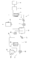
- the electrolysis apparatus 1 has an electrolysis cell 2 as shown in FIG.
- the electrolysis cell 2 is a non-diaphragm type, and an anode and a cathode constituted by diamond electrodes are arranged inside without being separated by a diaphragm, and a DC power source 3 is connected to both electrodes as a power source.
- the DC power supply 3 is connected to a power supply control unit 4 that controls the direction of the voltage applied to the anode and cathode.
- the power supply control unit 4 can be configured by, for example, a switch provided with a switch that switches a path for applying a voltage from the DC power supply 3 to the anode and the cathode.
- the electrolysis cell 2 has an anode 20 and a cathode 21 that are plate-shaped and made of diamond electrodes, and a spacer 22 is disposed between the anode 20 and the cathode 21.
- a flow path 23 is secured between the anode 20 and the cathode 21.
- the diamond electrode is preferably formed by forming a diamond thin film on a substrate and imparting conductivity by doping boron in a range of preferably 50 to 20,000 ppm with respect to the carbon content of the diamond thin film. Can be used.
- the electrolytic cell is described as having an anode and a cathode as electrodes, but a bipolar electrode may be provided in addition to the anode and cathode as electrodes.
- a bipolar electrode may be provided in addition to the anode and cathode as electrodes.
- the spacer 22 is formed with a liquid inlet hole 22 a on the inlet side and a liquid outlet hole 22 b on the outlet side.
- the liquid inlet hole 22 a and the liquid outlet hole 22 b are considerably narrower than the flow path 23.
- the liquid inlet hole 22a and the liquid outlet hole 22b correspond to the narrow channel portion of the present invention.
- an O-ring 24 is disposed as a sealing member between the spacer 22 and the anode 20 and the cathode 21 to ensure the sealing performance of the flow path 23.
- a material having insulation and corrosion resistance for example, made of polytetrafluoroethylene is desirable.
- the inner surfaces of the electrodes 20, 21, the corners of the spacer 22, and the inner surface side of the O-ring 24 serve as a retention portion 25 that inhibits the passage of sulfuric acid solution.
- the electrolysis cell 2 is arranged so that the inlet side is downward and the outlet side is upward so that the flow is upward.
- An electrolytic solution storage tank 10 is connected to the electrolytic cell 2 via a first circulation line 5, and a sulfuric acid solution can be circulated between the electrolytic cell 2 and the electrolytic solution storage tank 10. ing. That is, the feed side of the first circulation line 5 is connected to the electrolysis cell 2 so as to communicate with the inlet side of the electrolysis cell 2, and the return side of the first circulation line 5 communicates with the outlet side of the electrolysis cell 2. In this way, it is connected to the electrolytic cell 2.
- a gas-liquid separation tank 6 is interposed on the return side of the first circulation line 5.
- the gas-liquid separation tank 6 contains a sulfuric acid solution containing a gas, separates the gas in the sulfuric acid solution, and discharges it out of the system. A known one can be used. If liquid separation is possible, the structure is not particularly limited.
- a circulation pump 7 for circulating the sulfuric acid solution and a cooler 8 for cooling the sulfuric acid solution are interposed on the feed side of the first circulation line 5.
- the 1st circulation line 5 and the circulation pump 7 are equivalent to the liquid feeding part of this invention.
- the cooler 8 cools the sulfuric acid solution to a liquid temperature suitable for electrolysis such as 40 to 70 ° C.
- the configuration of the present invention is not particularly limited.
- the electrolytic cell 2, the DC power supply 3, the power supply control unit 4, the first circulation line 5, the gas-liquid separation tank 6, the circulation pump 7, and the cooler 8 constitute the electrolysis apparatus of the present invention.
- the electrolyte storage tank 10 is connected to the feed side of the second circulation line 11 via a feed pump 12.
- a heater 13 is interposed in the liquid feeding direction of the second circulation line 11.
- the front end side in the liquid feeding direction of the second circulation line 11 is connected to the single wafer cleaning device 15.
- the heater 13 has a quartz pipe line, and for example, the sulfuric acid solution is heated in a transient manner by a near infrared heater, so that the sulfuric acid solution has a liquid temperature of 150 to 220 ° C. in the single wafer cleaning device 15. Rapid heating of the sulfuric acid solution as possible.
- the electronic material substrate 100 is fixed by being mounted on a turntable, and the persulfuric acid-containing sulfuric acid solution is flowed from the nozzle onto the semiconductor material.
- the cleaning apparatus is described as a single wafer type.
- the present invention is not limited to this type of cleaning apparatus, and is a batch type cleaning apparatus. May be.
- the return side of the second circulation line 11 is connected to the single wafer cleaning device 15. On the return side of the second circulation line 11, a pump 16, a reaction tank 17, a liquid feed pump 18, and a cooler 19 are sequentially provided along the return direction. The side is connected to the electrolyte storage tank 10.
- the operation of the cleaning system having the above configuration will be described.
- a sulfuric acid solution having a sulfuric acid concentration of 85 to 96% by mass and a liquid temperature of 50 to 80 ° C. is stored.
- the sulfuric acid solution is fed through the first circulation line 5 by the circulation pump 7, adjusted to a temperature (40 to 70 ° C.) suitable for electrolysis by the cooler 8, introduced to the liquid inlet side of the electrolytic cell 2, It flows into the flow path 23 from the liquid inlet 22a.
- a voltage is applied in the forward direction between the anode and the cathode by the DC power source 3, and the sulfuric acid solution introduced into the electrolytic cell 2 is electrolyzed.
- an oxidizing substance containing persulfuric acid is generated on the anode side, oxygen gas is generated, and hydrogen gas is generated on the cathode side.
- These oxidizing substances and gases flow through the flow path 23 in a mixed state with the sulfuric acid solution.
- the sulfuric acid solution flowing through the flow path 23 is sent to the first circulation line 5 through the liquid discharge hole 22b.
- the sulfuric acid solution sent out from the outlet hole 22b is sent to the gas-liquid separation tank 6 through the first circulation line 5, and the gas is separated.
- the gas is discharged out of the system and safely processed by a catalyst device (not shown).
- the sulfuric acid solution from which the gas has been separated in the gas-liquid separation tank 6 contains persulfuric acid, and is further returned to the electrolytic solution storage tank 10 through the return side of the first circulation line 5 and then repeatedly sent to the electrolytic cell 2.
- the concentration of persulfuric acid is increased by electrolysis.
- a part of the sulfuric acid solution in the electrolytic solution storage tank 10 is sent to the heater 13 by the liquid feed pump 12 through the feed side of the second circulation line 11.
- the sulfuric acid solution containing persulfuric acid is heated by the near infrared heater while passing through the flow path.
- the sulfuric acid solution When sending the solution, the sulfuric acid solution should be less than 1 minute, preferably less than 20 seconds, more preferably less than 1 second from the inlet of the heater 13 until it is used in the single wafer cleaning device 15. It is desirable that the flow rate be adjusted to be less than 10 seconds.
- the flow rate at 500 to 2000 mL / min. Is set to an appropriate amount, and the flow rate of the heater 13 is set so that the liquid passing time is less than 1 minute at the flow rate.
- the length, the channel cross-sectional area, the line length of the second circulation line 11 on the downstream side, the channel cross-sectional area, and the like are set.
- the sulfuric acid solution when supplied to the electronic material substrate 100, it has a liquid temperature in the range of 150 ° C. to 220 ° C.
- a semiconductor material such as a silicon wafer provided with a resist ion-implanted at 1 ⁇ 10 12 to 1 ⁇ 10 16 atoms / cm 2 is an object to be cleaned.
- the electronic material substrate 100 is rotated on a turntable (not shown), and a high temperature sulfuric acid solution containing persulfuric acid is poured little by little from a nozzle (not shown) so as to come into contact with the contaminants such as resist on the electronic material substrate 100. Effectively strips and removes.
- the sulfuric acid solution used for cleaning is discharged from the single wafer cleaning device 15, and sent to the reaction tank 17 by the pump 16 through the return side of the second circulation line 11 and stored.
- the sulfuric acid solution stored in the reaction tank 17 contains residual organic substances such as resist washed by the single wafer cleaning device 15, and the residual organic substances are contained in the sulfuric acid solution while being stored in the reaction tank 17. It is oxidatively decomposed by oxidants.
- the storage time of the sulfuric acid solution in the reaction tank 17 can be arbitrarily adjusted depending on the content of residual organic matter and the like. At this time, a high-temperature sulfuric acid solution containing persulfuric acid is continuously supplied from the single wafer cleaning device 15, and the reaction tank 17 is maintained at an appropriate temperature.
- the sulfuric acid solution obtained by oxidizing and decomposing residual organic substances is circulated to the electrolyte storage tank 10 by the liquid feed pump 18 through the cooler 19 interposed in the second circulation line 11.
- the high-temperature sulfuric acid solution is circulated to the electrolytic solution storage tank 10
- decomposition of persulfuric acid in the sulfuric acid solution stored in the electrolytic solution storage tank 10 is promoted.
- After being cooled to an appropriate temperature of about 50 to 80 ° C. it is introduced into the electrolytic solution storage tank 10.
- the sulfuric acid solution introduced into the electrolytic solution storage tank 10 is fed to the electrolytic cell 2 by the feeding side of the first circulation line 5 to generate persulfuric acid by electrolysis, and is returned by the return side of the first circulation line 5.
- a drain line is branched and connected to the second circulation line 11 on the upstream side of the reaction tank 17 so that the sulfuric acid solution is not sent to the reaction tank 17 at an appropriate time. You may comprise so that it can drain outside. By discharging the sulfuric acid solution little by little from the drainage line as needed, it is possible to prevent the resist dope element and other non-oxidatively decomposed substances accumulated in the solution in the system from accumulating to a high concentration.
- the operation can be performed by opening / closing control of an opening / closing valve provided in the reflux line or the drain line.
- the electrode surface in particular, the peripheral portion of the electrode and the staying portion 25 in the shaded portion of the O-ring, lead to sulfur or sulfur generation.
- a seed is generated. If this is left unattended, it grows gradually as described above, leading to separation and blockage of the narrow channel.
- the duration of electrolysis reaches a predetermined time
- the number of processed electronic material substrates 100 reaches a predetermined number
- a reversal operation for reversing the voltage applied between the anode 20 and the cathode 21 from the DC power supply 3 is performed to perform electrolysis.
- the sulfur deposits deposited in the vicinity of the cathode 21 and the like are reversed and dissolved by the oxidizing substance generated in the vicinity of the cathode 21 functioning as the anode, and move together with the sulfuric acid solution.
- inversion of organic matter countermeasures is limited because the cathode and the anode are different, but in this embodiment, all electrodes are diamond electrodes, so normal operation can be performed for a long time (10 to 100 hours) with the polarity reversed. it can.
- operation after inversion can be made into the case where normal electrolysis time reaches the predetermined time defined beforehand.
- the predetermined time can be determined in consideration of the accumulated energization amount, the concentration of the sulfuric acid solution, the temperature, the flow rate, and the like, or may be determined experimentally.
- the reversing operation can be performed.
- the duration of operation after pole reversal may be non-constant, but if the diamond electrode has a diamond layer with a uniform thickness on both sides, the duration will be reduced in order to equalize diamond wear during operation. Is desirable to be constant.
- the result of estimating the degree of precipitation of sulfur in the electrolytic cell can be used. That is, the inversion operation is performed when the estimated degree of sulfur deposition reaches a predetermined degree.
- the degree of sulfur deposition can be determined by the electrolysis voltage that rises during electrolysis at a constant current as described above. That is, when the voltage reaches a predetermined electrolytic voltage, the reversal operation is performed assuming that sulfur deposition is progressing.
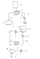
- Embodiment 2 Next, a second embodiment in which the electrolysis apparatus 1 is applied to a batch-type cleaning tank 30 will be described with reference to FIG.
- symbol is attached
- An electrolytic solution storage tank 10 is connected to the electrolytic cell 2 via a first circulation line 5.
- a gas-liquid separation tank 6 is provided on the return side of the first circulation line 5, and a circulation pump 7 and a cooler 8 are sequentially provided on the feed side of the first circulation line 5.
- the batch-type cleaning tank 30 has a drain side and a liquid inlet side connected by a second circulation line 31, and a liquid feed pump 32 and a heater 33 are interposed on the return side of the second circulation line 31. Yes.
- the electronic material substrate 100 is immersed in a sulfuric acid solution in the batch-type cleaning tank 30, and the resist or the like attached to the electronic material substrate 100 is peeled and cleaned.
- the sulfuric acid solution is circulated while controlling the temperature of the batch-type cleaning tank 30 to be 120 to 190 ° C. by a heating unit (not shown) such as a heater or a heat exchanger.
- a return third circulation line 35 is branched and connected to the second circulation line 31 on the downstream side of the liquid feed pump 32 and the upstream side of the heater 33, and the liquid feed end of the return third circulation line 35 is connected.
- the side is connected to the electrolytic solution storage tank 10 via the cooler 37.
- a feed third circulation line 34 is connected to the electrolytic solution storage tank 10 via a feed pump 36.
- the feed third circulation line 34 joins and is connected to the second circulation line 31 on the downstream side of the heater 33.
- the heater 33 can have the same configuration as the heater 13.
- a sulfuric acid solution having a sulfuric acid concentration of 85 to 96 mass% and a liquid temperature of 50 to 90 ° C. is stored in the electrolytic solution storage tank 10, and the sulfuric acid solution is fed through the first circulation line 5 by the circulation pump 7, and is cooled. 8 is adjusted to a temperature suitable for electrolysis (40 to 80 ° C.) and introduced into the flow path 23 from the liquid inlet 22 a of the electrolytic cell 2.
- a voltage is applied in the forward direction between the anode and the cathode by the DC power source 3, and the sulfuric acid solution introduced into the electrolytic cell 2 is electrolyzed.
- the electrolyzed sulfuric acid solution is sent to the first circulation line 5 through the liquid discharge hole 22b, and the gas is separated in the gas-liquid separation tank 6.
- the sulfuric acid solution from which the gas has been separated in the gas-liquid separation tank 6 is returned to the electrolytic solution storage tank 10 through the return side of the first circulation line 5, and then repeatedly sent to the electrolytic cell 2, where the persulfuric acid is electrolyzed. Concentration is increased.
- the persulfuric acid concentration becomes moderate a part of the sulfuric acid solution in the electrolytic solution storage tank 10 is sent to the second circulation line 31 downstream of the heater 33 by the liquid feed pump 36 through the third circulation line 34. To join the sulfuric acid solution in the second circulation line 31.
- the combined sulfuric acid solution is introduced into the batch type washing tank 30.
- the sulfuric acid solution in the batch-type cleaning tank 30 is circulated through the second circulation line 31 by the liquid feed pump 32. At this time, it is heated by the heater 33 and introduced into the batch-type cleaning tank 30. In the heater 33, the persulfuric acid-containing sulfuric acid solution is heated by the heater while passing through the flow path. At this time, when mixed with the sulfuric acid solution sent in the third feed circulation line 34 and fed into the batch-type washing tank 30, heating is performed so as to have a liquid temperature in the range of 120 ° C. to 190 ° C. .
- the electronic material substrate 100 is cleaned.
- the sulfuric acid solution used for the washing is heated by the heater 33 while being partly circulated in the second circulation line 31 and returned to the batch-type washing tank 30, and the remainder is returned to the electrolytic solution in the third circulation line 35. Return to storage tank 10. At this time, the sulfuric acid solution is cooled to 40 to 70 ° C. suitable for electrolysis by the cooler 37.
- the sulfuric acid solution is sent to the electrolytic cell 2 by the circulation pump 7 through the first circulation line 5 to generate persulfuric acid, and is returned to the electrolytic solution storage tank 10.
- the electronic material substrate 100 can be cleaned while the persulfuric acid concentration is stable.
- sulfur or chemical species that lead to sulfur generation is generated in the retention portion 25.
- a reversal operation for reversing the voltage applied from the DC power supply 3 between the anode 20 and the cathode 21 is performed, and electrolysis is continuously performed. Thereby, the deposit of sulfur deposited in the vicinity of the cathode or the like is dissolved.
- This example has the same configuration as that of the second embodiment except that the power supply control unit 4 is not provided in the second embodiment, and will be described with reference to FIG.
- a forward voltage is always applied to the anode side and the cathode side by the DC power source 3, so that the sulfuric acid solution can be electrolyzed.
- the sulfuric acid solution can be electrolyzed to effectively clean the material to be cleaned such as a semiconductor substrate.
- sulfur deposits are generated in the electrolytic cell, and the separated sulfur deposits block the narrow channel portion of the electrolytic cell 2 to reduce the cleaning ability or make the cleaning itself difficult. It becomes. Further, when the peeled sulfur deposits reach a narrow flow path such as a liquid inlet hole of the electrolytic cell, there arises a problem that the flow path is blocked or the flow is deteriorated.
- Electrolysis apparatus E.
- Electrolysis cell E.
- Anode E.
- Cathode Spacer 22a Inlet hole 22b Outlet hole 23 Channel 3
- DC power supply Power supply control part
- First circulation line Circulation pump 8
- Cooler Electrolyte storage tank 15 Single wafer Type cleaning device 30 Batch type cleaning tank
Landscapes
- Chemical & Material Sciences (AREA)
- Engineering & Computer Science (AREA)
- Chemical Kinetics & Catalysis (AREA)
- Electrochemistry (AREA)
- Materials Engineering (AREA)
- Metallurgy (AREA)
- Organic Chemistry (AREA)
- Inorganic Chemistry (AREA)
- Automation & Control Theory (AREA)
- Electrolytic Production Of Non-Metals, Compounds, Apparatuses Therefor (AREA)
- Cleaning Or Drying Semiconductors (AREA)
- Electrodes For Compound Or Non-Metal Manufacture (AREA)
Abstract
Description
硫酸を電気分解して過硫酸を生成する方法の1つでは、電解セル内で電極間に硫酸溶液を通液しつつ、電極のうち陽極と陰極との間に直流電圧を印加して電解を行う。この電解セルの構造として、単極セル(陽極・陰極が一対)、バイポーラ電極を用いた複極セルなどがあるが、一対の陽極・陰極の関係は同一である。極間距離を一定に保つために通常はスペーサが用いられ、電解液をシールするためにOリングなどのシーリング部材が使われている。このような構造の電解セルには、例えば本願発明者が提案しているものがある(特許文献1参照)。
よって運転を継続していると、電極面、特に電極周端部やOリングの陰になる部分に硫黄または硫黄生成に繋がる化学種が生成する。微細なS粒子が電極面に付着・成長すると、やがて電極から剥がれて電解液の流れに乗って移動し、電解セル出液孔や電解セル入液孔などの狭小な部分に付着・蓄積して、やがて閉塞に至るという問題が生じる恐れがある。この問題は、硫酸濃度が高い場合、電流密度が高い場合、および極間電圧が高い場合に生じ易いと考えられる。
Oリング部や出液孔付近に硫黄が蓄積する様子を図7(b)に示す。図中Aのように硫黄が析出し、遂には析出物が剥離して移動してやがて図中Bのようにセル出口やセル入口を閉塞するものと推定される。
前記電極の陽極と陰極との間に順方向の電圧を印加して前記電解を行う通常動作を行うとともに、前記通常動作間に前記陽極と陰極とに印加する電圧を逆転させる転極動作を行って、前記通常動作時に電解セル内で生成された硫黄析出物を前記転極動作時に前記硫酸溶液中に溶解させることを特徴とする。
第3の本発明の硫酸電解方法は、第1または第2の本発明において、前記電解セル内に、通液される前記硫酸溶液が滞留する滞留部を有していることを特徴とする。
第4の本発明の硫酸電解方法は、第1~第3の本発明のいずれかにおいて、前記電解セル内に前記硫酸溶液が流れる狭小流路部を有していることを特徴とする。
第5の本発明の硫酸電解方法は、第3の本発明において、前記電極間に硫酸溶液の流路を確保するスペーサが配置されており、該スペーサまたは該スペーサと他部材とで前記滞留部が形成されていることを特徴とする。
第6の本発明の硫酸電解方法は、第5の本発明において、前記電極と前記スペーサとの間にシーリング部材が介設されており、少なくとも該シーリング部材で前記滞留部が形成されていることを特徴とする。
第7の本発明の硫酸電解方法は、第5または第6の本発明において、前記スペーサに狭小流路部として前記硫酸溶液が通過する出液孔が形成されていることを特徴とする。
第8の本発明の硫酸電解方法は、第5~第7の本発明のいずれかにおいて、前記スペーサに狭小流路部として前記硫酸溶液が通過する入液孔が形成されていることを特徴とする。
第9の本発明の硫酸電解方法は、第1~第8の本発明のいずれかにおいて、前記電解セルの出口から前記電解セルの入口までを接続する循環ラインが設けられており、該循環ライン及び/又は電解セルの滞留部の上流側に狭小流路部を有することを特徴とする。
第10の本発明の硫酸電解方法は、第1~第9の本発明のいずれかにおいて、前記転極動作は、通常動作が所定の時間継続することによって実行されることを特徴とする。
第11の本発明の硫酸電解方法は、第1~第10の本発明のいずれかにおいて、前記転極動作は、前記硫黄の析出状態の判定に基づいて実行されることを特徴とする。
(a)前記電解セル内の前記硫酸の濃度が85質量%以上
(b)前記電解セル入口の硫酸温度が70℃以上
(c)前記電解における電流密度が50A/dm2以上
前記電解セル内に、互いの間隙で前記硫酸溶液が通液するように配置され、かつ少なくとも接液面が導電性ダイヤモンドで構成された少なくとも陽極と陰極とを含む複数の電極と、
前記電極間の間隙を確保するスペーサと、
該スペーサに有する前記硫酸溶液が流れる狭小流路部と、
前記電解セルに対し硫酸溶液の送液を行う送液部と、
前記電極の前記陽極と前記陰極との間に電圧を印加する電源部と、
前記電源部に対し、通常の電解時に前記陽極と前記陰極との間に順方向の電圧を印加させるとともに予め定めた条件で前記陽極と前記陰極との間に印加する電圧を逆転する転極を実行させる制御を行う電源制御部と、を備えることを特徴とする。
前記電解セル内に、互いの間隙で前記硫酸溶液が通液するように配置され、かつ少なくとも接液面が導電性ダイヤモンドで構成された少なくとも陽極と陰極を含む複数の電極と、
前記電極間の間隙を確保するスペーサと、
該スペーサまたは該スペーサと他部材とで前記硫酸溶液が滞留する滞留部と、
前記電極の前記陽極と前記陰極との間に電圧を印加する電源部と、
前記電源部に対し、通常の電解時に前記陽極と前記陰極との間に印加する電圧を逆転する転極を実行させる制御を行う電源制御部と、を備えることを特徴とする。
この操作を一定のインターバルで繰り返すことにより、硫黄の蓄積・セルの閉塞を防ぐことができる。インターバルの決め方は、経験に基づく一定の運転時間や洗浄などを行った処理枚数に応じたものとしても良いが、硫黄が蓄積してくると、所定電流を流すのに要する電圧(極間電圧)が上昇してくるので、電流制御で通電している際に電圧を常時監視して電圧が所定値まで上昇することにより転極動作を開始することとしても良い。また、上記転極を実行している際にも電圧を監視して、該電圧が所定値まで下降することにより、現在の転極動作を停止するようにしてもよい。
電解液中では硫酸や水分子が次のように解離して、SO4 2-、HSO4 -、H+などのイオンが存在する。
HSO4 - ⇔ SO4 2-+H+
H2O ⇔ OH-+H+
陰極ではH+が引き寄せられ、下記反応式に示すように電子を受け取って水素ガスH2になる。
2H++2e-→H2
2HSO4 -→S2O8 2-+2H++2e-
2SO4 2-→S2O8 2-+2e-
また、陽極では、下記反応式に示すように水の電気分解も起こって酸素ガスO2が発生する。
2OH-→O2+2H++4e-
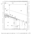
Pourbaixの線図に基づいて、硫酸濃度=92質量%、温度=60℃での硫酸と水のポテンシャルを描き、並べて表すと、図6のようになる。図中の式番号は、図4、5に示された線図上の式に基づくものである。
過硫酸の生成効率からすると、実際に陽極を通過する電子のうち80~90%相当がO2の生成に関与するものであり、残りの10~20%が過硫酸の生成に寄与するものである。O2は系外に排出され、過硫酸は酸化反応に用いられた後に硫酸になってセルに戻るように液を循環使用すると、硫酸を電解する電解セルでは水が消費されて硫酸濃度が濃くなっていくことになる。
上記のように、陰極で硫黄の生成を完全に防ぐことは原理上難しいが、陽極で生成した酸化性物質(過硫酸など)によって硫黄を酸化して硫酸に戻すことができる。液が滞留してうまく酸化できない場合には、転極を行って滞留部付近で過硫酸を生成して、滞留部の硫黄を除去するのが適切である。
滞留部は部材の隅など表面の角度が急激に変化する凹部に形成されやすく、電極とスペーサの交叉部、シーリング部材と電極やスペーサとの交叉部などに形成される。
以上のことから硫黄析出物の問題は、以下の3条件のいずれか1つ以上を満たすときに発生しやすく、このような条件下では特に本発明を実施することが望ましい。
(a)電解セル内の硫酸濃度が85質量%以上
(b)電解セル入口の硫酸温度が70℃以上
(c)電流密度が50A/dm2以上
硫酸電解液による電子材料洗浄では洗浄後のTOC濃度は0~10mg/lであり、有機物がほとんど存在しない。
以下に、本発明の一実施形態の電解装置を備える洗浄システムを添付図面に基づいて説明する。
電解装置1は、図1に示すように電解セル2を有している。電解セル2は無隔膜型であり、ダイヤモンド電極により構成された陽極および陰極が隔膜で隔てることなく内部に配置され、両電極には電源部として直流電源3が接続されている。直流電源3には、前記陽極、陰極に印加する電圧の方向を制御する電源制御部4が接続されている。電源制御部4は、例えば直流電源3から陽極および陰極に電圧を印加する経路を切り替える切り替え器を備えるものなどによって構成することができる。
なお、この実施形態の説明では、電解セルは、電極として陽極と陰極とを有するものとして説明しているが、電極として陽極、陰極以外にバイポーラ電極を備えるものであってもよい。また、電解セルとしては、電極を互いに間隙を有するように多層に配して各電極間で硫酸溶液を通液して電解するものであってもよい。
上記電解セル2では、電極20、21の内面とスペーサ22の角部やOリング24の内面側が硫酸溶液の通液が阻害される滞留部25となっている。電解セル2は上向流となるように入口側が下方、出口側が上方になるよう配置する。
第1の循環ライン5の戻り側には気液分離槽6が介設されている。該気液分離槽6は、気体を含んだ硫酸溶液を収容して硫酸溶液中の気体を分離して系外に排出するものであり、既知のものを用いることができ、本発明としては気液分離が可能であれば、特にその構成が限定されるものではない。
第2の循環ライン11の送液方向には、加熱器13が介設されている。加熱器13の下流側で第2の循環ライン11の送液方向先端側は枚葉式洗浄装置15に接続されている。
上記加熱器13は、石英製の管路を有し、例えば近赤外線ヒーターによって硫酸溶液を一過式で加熱し、枚葉式洗浄装置15内で硫酸溶液が150~220℃の液温が得られるように硫酸溶液を急速加熱する。
なお、この実施形態では、洗浄装置が枚葉式のものであるとして説明しているが、本発明としては、洗浄装置の種別がこれに限定されるものではなく、バッチ式の洗浄装置であってもよい。
電解液貯留槽10には、硫酸濃度85~96質量%、液温度50~80℃の硫酸溶液が貯留される。前記硫酸溶液は、循環ポンプ7によって第1の循環ライン5を通して送液され、冷却器8で電解に好適な温度(40~70℃)に調整されて電解セル2の入液側に導入され、入液孔22aから流路23内に流入する。
電解セル2では、直流電源3によって陽極、陰極間に順方向に電圧が印加され、電解セル2内に導入された硫酸溶液が電解される。なお、該電解によって電解セル2では、陽極側で過硫酸を含む酸化性物質が生成されるとともに酸素ガスが発生し、陰極側では水素ガスが発生する。これらの酸化性物質とガスは、前記硫酸溶液と混在した状態で流路23を流れる。流路23を流れる硫酸溶液は、出液孔22bを通って第1の循環ライン5に送られる。出液孔22bから送り出された硫酸溶液は、第1の循環ライン5を通して気液分離槽6に送られ、前記ガスが分離される。なお、前記ガスは本システム系外に排出されて触媒装置(図示しない)などにより安全に処理される。
加熱器13では、過硫酸を含む硫酸溶液が流路を通過しながら近赤外線ヒーターによって加熱される。送液に際し硫酸溶液は、加熱器13の入口から枚葉式洗浄装置15で使用されるまでの通液時間が1分未満となるように、好ましくは20秒未満になるように、より好ましくは10秒未満になるように、流量が調整されているのが望ましい。なお、枚葉式洗浄装置15では、500~2000mL/min.での流量が適量とされており、該流量において、前記通液時間が1分未満となるように、加熱器13の流路の長さ、流路断面積およびその下流側での第2の循環ライン11のライン長、流路断面積などを設定する。枚葉式洗浄装置15内では、電子材料基板100に硫酸溶液が供給された際に150℃~220℃の範囲の液温を有している。
該電子材料基板100を図示しない回転台上で回転させつつ図示しないノズルから過硫酸を含む高温の硫酸溶液を少量ずつ流し落とすなどして接触させることで電子材料基板100上のレジストなどの汚染物を効果的に剥離除去する。
洗浄に使用された硫酸溶液は、枚葉式洗浄装置15から排出され、第2の循環ライン11の戻り側を通してポンプ16により反応槽17に送液され貯留される。反応槽17に貯留された硫酸溶液には枚葉式洗浄装置15で洗浄されたレジストなどの残留有機物が含まれており、反応槽17に貯留されている間に、残留有機物が硫酸溶液に含まれる酸化性物質によって酸化分解される。なお、反応槽17における前記硫酸溶液の貯留時間は、残留有機物などの含有量などによって、任意に調整することができる。この際に、枚葉式洗浄装置15から継続して高温かつ過硫酸を含む硫酸溶液が供給されており、反応槽17は適温に維持される。
また、高温の硫酸溶液が電解液貯留槽10に環流されると、電解液貯留槽10に貯留されている硫酸溶液中の過硫酸の分解が促進されてしまうため、前記硫酸溶液は冷却器19により50~80℃程度の適温に冷却された後、電解液貯留槽10内に導入されている。電解液貯留槽10内に導入された硫酸溶液は、第1の循環ライン5の送り側によって電解セル2に送液されて電解により過硫酸が生成され、第1の循環ライン5の戻り側により再度電解液貯留槽10に送られる。この循環を繰り返すことで過硫酸が継続して生成される。
上記動作によって、過硫酸を含む硫酸溶液が送液され、環流することで、使用側である枚葉式洗浄装置15に高濃度の過硫酸を含む高温の洗浄液を連続して供給することが可能になる。
排液ラインより随時硫酸溶液を少量ずつ排出することにより、系内の溶液中に蓄積するレジストドープ元素やその他の酸化分解されない物質が高濃度に至るまで蓄積するのを防止することができる。該動作は、環流ラインや排液ラインに設けた開閉弁の開閉制御などにより行うことができる。
上記動作を繰り返せば、安定した電解を長い時間継続して行うことが可能になる。
一般に、有機物付着対策の転極は、陰極と陽極が異なるので転極時間は限られるが、この実施形態では全てダイヤモンド電極なので転極したまま通常運転を長時間(10~100時間)行うことができる。
転極後の運転の継続時間を一定にしないこともできるが、ダイヤモンド電極が両面に均等の厚みでダイヤモンド層を積層している場合は、運転に伴うダイヤモンドの磨耗を均等にするため、継続時間を一定にすることが望ましい。
また、転極動作を実行する他のタイミングとしては、電解セル中の硫黄の析出程度を推定した結果を利用することができる。すなわち、推定される硫黄の析出程度が、予め定めた程度に達した場合に、転極動作を実行する。硫黄の析出程度は、前述したように定電流で電解を行っている際に上昇する電解電圧によって判定することができる。すなわち該電圧が予め定めた電解電圧に達すると、硫黄の析出が進行しているものとして転極動作を行う。
次に、上記電解装置1をバッチ式洗浄槽30に適用した実施形態2を図2に基づいて説明する。なお、この実施形態2で前記実施形態1と同様の構成については同一の符号を付して説明を省略または簡略化する。
上記電解セル2には、電解液貯留槽10が第1の循環ライン5を介して接続されている。第1の循環ライン5の戻り側には気液分離槽6が介設され、第1の循環ライン5の送り側には、循環ポンプ7、冷却器8が順次介設されている。
第2の循環ライン31には、送液ポンプ32の下流側かつ加熱器33の上流側で、戻り第3循環ライン35が分岐して接続されており、戻り第3循環ライン35の送液端側は冷却器37を介して電解液貯留槽10に接続されている。
上記加熱器33は、前記加熱器13と同様の構成とすることができる。
電解液貯留槽10には、硫酸濃度85~96質量%、液温度50~90℃の硫酸溶液が貯留され、該硫酸溶液が循環ポンプ7によって第1の循環ライン5を通して送液され、冷却器8で電解に好適な温度(40~80℃)に調整されて電解セル2の入液孔22aから流路23に導入される。
電解セル2では、直流電源3によって陽極、陰極間に順方向に電圧が印加され、電解セル2内に導入された硫酸溶液が電解される。電解された硫酸溶液は、出液孔22bを通って第1の循環ライン5に送られ、気液分離槽6でガスが分離される。
気液分離槽6でガスが分離された前記硫酸溶液は、第1の循環ライン5の戻り側を通して電解液貯留槽10に戻された後、繰り返し電解セル2に送られ、電解により過硫酸の濃度が高められる。過硫酸濃度が適度になると、電解液貯留槽10内の硫酸溶液の一部は送り第3循環ライン34を通して送液ポンプ36によって加熱器33の下流側の第2の循環ライン31へと送られて第2の循環ライン31の硫酸溶液に合流する。合流した硫酸溶液はバッチ式洗浄槽30内に導入される。
また、バッチ式洗浄槽30内の硫酸溶液が、送液ポンプ32によって第2の循環ライン31を通して循環される。この際に加熱器33で加熱されてバッチ式洗浄槽30内に導入される。
加熱器33では、過硫酸含有硫酸溶液が流路を通過しながらヒーターによって加熱される。このとき前記送り第3循環ライン34で送られた硫酸溶液と混合されて、バッチ式洗浄槽30内に供給された際に120℃~190℃の範囲の液温を有するように加熱が行われる。
上記硫酸溶液の循環を繰り返すことで、過硫酸濃度が安定した状態で電子材料基板100の洗浄を行うことができる。
上記洗浄システムにおいて稼働状態を継続することで、電解セル2内では、前記したように滞留部25に硫黄または硫黄生成に繋がる化学種が生成する。この実施形態でも所定のタイミングで電源制御部4の制御によって、直流電源3から陽極20と陰極21間に印加される電圧を逆転させる転極動作を行い、電解を継続して行う。これにより、陰極近傍などに析出した硫黄の析出物が溶解される。転極動作をある程度継続することで、硫黄析出部をなくし、または、小さくすることで、その後、安定した電解を継続することを可能にする。
この例は、実施形態2において電源制御部4を有しない以外は、実施形態2と同様の構成を有しているものであり、図3に基づいて説明する。電解セル2では、直流電源3によって、常時陽極側と陰極側とに順方向の電圧が印加されており、硫酸溶液の電解を行うことができる。
この例においても、硫酸溶液を電解して半導体基板などの被洗浄材を効果的に洗浄することができる。しかし、経時的には電解セル内で硫黄の析出物が生成され、剥離した硫黄析出物が電解セル2の狭小流路部を閉塞するなどして洗浄能力が低下したり、洗浄自体が困難になったりする。また、剥離した硫黄析出物が、電解セルの入液孔などの狭小流路に達すると、流路が閉塞したり流れが悪くなったりする問題が発生する。
硫酸濃度=92質量%、電解セル入口液温度=60℃、電流密度=35A/dm2において運転を継続した。50時間継続して電解を行うごとに転極を行い、10回50時間継続、転極を繰り返した後にセルを開放して内部検査を行ったところ、硫黄の付着は全く認められなかった。
硫酸濃度=85質量%、電解セル入口液温度=50℃、電流密度=50A/dm2において運転を継続した。ウエハを50枚ずつ処理し、40バッチごとに転極を行った。これを8回繰り返した後に、セルを開放して内部検査を行ったところ、硫黄の付着は全く認められなかった。
図3に示す、転極機能を持たないバッチ式洗浄システムを用いて、硫酸濃度=85質量%、電解セル入口液温度=50℃、電流密度=50A/dm2において運転を継続したところ、100バッチを越えるころから電圧が上昇し始め、徐々に液流量も低下してきた。1セル当りの液流量が半減したところでセルを開放して点検したところ、セル出口部流路に硫黄による閉塞が見られた。
2 電解セル
20 陽極
21 陰極
22 スペーサ
22a 入液孔
22b 出液孔
23 流路
3 直流電源
4 電源制御部
5 第1の循環ライン
7 循環ポンプ
8 冷却器
10 電解液貯留槽
15 枚葉式洗浄装置
30 バッチ式洗浄槽
Claims (14)
- 電解セル内で、少なくとも接液面が導電性ダイヤモンドによって構成された少なくとも陽極と陰極とを含む複数の電極のうち前記陽極と前記陰極との間に70質量%以上の硫酸溶液を通液しつつ電解を行って過硫酸を生成する電解方法であって、
前記電極の陽極と陰極との間に順方向の電圧を印加して前記電解を行う通常動作を行うとともに、前記通常動作間に前記陽極と陰極とに印加する電圧を逆転させる転極動作を行って、前記通常動作時に電解セル内で生成された硫黄析出物を前記転極動作時に前記硫酸溶液中に溶解させることを特徴とする硫酸電解方法。 - 前記電解セル外から前記電解セル内に硫酸溶液を入液しつつ前記電解を行い、電解した前記硫酸溶液を前記電解セル外に出液することを特徴とする請求項1記載の硫酸電解方法。
- 前記電解セル内に、通液される前記硫酸溶液が滞留する滞留部を有していることを特徴とする請求項1または2に記載の硫酸電解方法。
- 前記電解セル内に前記硫酸溶液が流れる狭小流路部を有していることを特徴とする請求項1~3のいずれかに記載の硫酸電解方法。
- 前記電極間に硫酸溶液の流路を確保するスペーサが配置されており、該スペーサまたは該スペーサと他部材とで前記滞留部が形成されていることを特徴とする請求項3記載の硫酸電解方法。
- 前記電極と前記スペーサとの間にシーリング部材が介設されており、少なくとも該シーリング部材で前記滞留部が形成されていることを特徴とする請求項5に記載の硫酸電解方法。
- 前記スペーサに狭小流路部として前記硫酸溶液が通過する出液孔が形成されていることを特徴とする請求項5または6に記載の硫酸電解方法。
- 前記スペーサに狭小流路部として前記硫酸溶液が通過する入液孔が形成されていることを特徴とする請求項5~7のいずれか1項に記載の硫酸電解方法。
- 前記電解セルの出口から前記電解セルの入口までを接続する循環ラインが設けられており、該循環ライン及び/又は電解セルの滞留部の上流側に狭小流路部を有することを特徴とする請求項1~8のいずれか1項に記載の硫酸電解方法。
- 前記転極動作は、通常動作が所定の時間継続することによって実行されることを特徴とする請求項1~9のいずれか1項に記載の硫酸電解方法。
- 前記転極動作は、前記硫黄の析出状態の判定に基づいて実行されることを特徴とする請求項1~10のいずれか1項に記載の硫酸電解方法。
- 以下の条件(a)~(c)の少なくとも1つを満たすことを特徴とする請求項1~11のいずれか1項に記載の硫酸電解方法。
(a)前記電解セル内の前記硫酸の濃度が85質量%以上
(b)前記電解セル入口の硫酸温度が70℃以上
(c)前記電解における電流密度が50A/dm2以上 - 硫酸溶液の入液と出液とが可能な電解セルと、
前記電解セル内に、互いの間隙で前記硫酸溶液が通液するように配置され、かつ少なくとも接液面が導電性ダイヤモンドで構成された少なくとも陽極と陰極とを含む複数の電極と、
前記電極間の間隙を確保するスペーサと、
該スペーサに有する前記硫酸溶液が流れる狭小流路部と、
前記電解セルに対し硫酸溶液の送液を行う送液部と、
前記電極の前記陽極と前記陰極との間に電圧を印加する電源部と、
前記電源部に対し、通常の電解時に前記陽極と前記陰極との間に順方向の電圧を印加させるとともに予め定めた条件で前記陽極と前記陰極との間に印加する電圧を逆転する転極を実行させる制御を行う電源制御部と、を備えることを特徴とする硫酸電解装置。 - 硫酸溶液の入液と出液とが可能な電解セルと、
前記電解セル内に、互いの間隙で前記硫酸溶液が通液するように配置され、かつ少なくとも接液面が導電性ダイヤモンドで構成された少なくとも陽極と陰極を含む複数の電極と、
前記電極間の間隙を確保するスペーサと、
該スペーサまたは該スペーサと他部材とで前記硫酸溶液が滞留する滞留部と、
前記電極の前記陽極と前記陰極との間に電圧を印加する電源部と、
前記電源部に対し、通常の電解時に前記陽極と前記陰極との間に印加する電圧を逆転する転極を実行させる制御を行う電源制御部と、を備えることを特徴とする硫酸電解装置。
Priority Applications (3)
| Application Number | Priority Date | Filing Date | Title |
|---|---|---|---|
| US14/000,239 US20130319875A1 (en) | 2011-02-28 | 2012-02-23 | Sulfuric acid electrolysis method and sulfuric acid electrolysis apparatus |
| KR1020137020767A KR20130135895A (ko) | 2011-02-28 | 2012-02-23 | 황산 전해 방법 및 황산 전해 장치 |
| CN2012800105271A CN103384731A (zh) | 2011-02-28 | 2012-02-23 | 硫酸电解方法及硫酸电解装置 |
Applications Claiming Priority (2)
| Application Number | Priority Date | Filing Date | Title |
|---|---|---|---|
| JP2011042427A JP2012180538A (ja) | 2011-02-28 | 2011-02-28 | 硫酸電解方法および硫酸電解装置 |
| JP2011-042427 | 2011-02-28 |
Publications (1)
| Publication Number | Publication Date |
|---|---|
| WO2012117927A1 true WO2012117927A1 (ja) | 2012-09-07 |
Family
ID=46757864
Family Applications (1)
| Application Number | Title | Priority Date | Filing Date |
|---|---|---|---|
| PCT/JP2012/054371 Ceased WO2012117927A1 (ja) | 2011-02-28 | 2012-02-23 | 硫酸電解方法および硫酸電解装置 |
Country Status (6)
| Country | Link |
|---|---|
| US (1) | US20130319875A1 (ja) |
| JP (1) | JP2012180538A (ja) |
| KR (1) | KR20130135895A (ja) |
| CN (1) | CN103384731A (ja) |
| TW (1) | TWI437127B (ja) |
| WO (1) | WO2012117927A1 (ja) |
Families Citing this family (7)
| Publication number | Priority date | Publication date | Assignee | Title |
|---|---|---|---|---|
| JP6284188B2 (ja) * | 2014-04-14 | 2018-02-28 | 学校法人神奈川大学 | フッ素系有機化合物の分解方法、及びフッ素系有機化合物の分解装置 |
| JP6191720B1 (ja) * | 2016-03-25 | 2017-09-06 | 栗田工業株式会社 | 過硫酸溶液製造供給装置及び方法 |
| CN106917104A (zh) * | 2017-03-17 | 2017-07-04 | 南开大学 | 一种用bdd电极电合成过硫酸盐的方法 |
| JP6866751B2 (ja) * | 2017-04-25 | 2021-04-28 | 栗田工業株式会社 | 洗浄システム |
| CN108043205B (zh) * | 2017-12-21 | 2019-05-24 | 双盾环境科技有限公司 | 一种自循环双氧水脱硫工艺 |
| JP7484407B2 (ja) * | 2020-05-18 | 2024-05-16 | 栗田工業株式会社 | 電解硫酸溶液製造システムの立上げ方法 |
| JP2024116818A (ja) * | 2023-02-16 | 2024-08-28 | 株式会社Screenホールディングス | 基板処理装置、および、基板処理方法 |
Citations (3)
| Publication number | Priority date | Publication date | Assignee | Title |
|---|---|---|---|---|
| JP2007262531A (ja) * | 2006-03-29 | 2007-10-11 | Kurita Water Ind Ltd | 電解セルおよび該電解セルを用いた硫酸リサイクル型洗浄システム |
| JP2008132468A (ja) * | 2006-10-31 | 2008-06-12 | Institute Of National Colleges Of Technology Japan | 電解式水処理方法 |
| JP2010156034A (ja) * | 2009-01-05 | 2010-07-15 | Japan Organo Co Ltd | 過硫酸製造装置及び過硫酸製造方法 |
Family Cites Families (6)
| Publication number | Priority date | Publication date | Assignee | Title |
|---|---|---|---|---|
| US3766037A (en) * | 1972-02-11 | 1973-10-16 | Andco Inc | Electrochemical processes for the removal of contaminants from aqueous media |
| JP3465367B2 (ja) * | 1994-08-23 | 2003-11-10 | 東陶機器株式会社 | イオンリッチ水生成装置 |
| CN1105082C (zh) * | 1996-10-15 | 2003-04-09 | 安德列亚斯·魏斯贝克 | 减少或防止形成水垢的方法 |
| JP4462146B2 (ja) * | 2004-09-17 | 2010-05-12 | 栗田工業株式会社 | 硫酸リサイクル型洗浄システムおよび硫酸リサイクル型過硫酸供給装置 |
| JP2006278838A (ja) * | 2005-03-30 | 2006-10-12 | Kurita Water Ind Ltd | 硫酸リサイクル型洗浄システム |
| JP5660279B2 (ja) * | 2009-03-24 | 2015-01-28 | 栗田工業株式会社 | 機能性溶液供給システムおよび供給方法 |
-
2011
- 2011-02-28 JP JP2011042427A patent/JP2012180538A/ja active Pending
-
2012
- 2012-02-23 CN CN2012800105271A patent/CN103384731A/zh active Pending
- 2012-02-23 WO PCT/JP2012/054371 patent/WO2012117927A1/ja not_active Ceased
- 2012-02-23 US US14/000,239 patent/US20130319875A1/en not_active Abandoned
- 2012-02-23 KR KR1020137020767A patent/KR20130135895A/ko not_active Ceased
- 2012-02-24 TW TW101106122A patent/TWI437127B/zh active
Patent Citations (3)
| Publication number | Priority date | Publication date | Assignee | Title |
|---|---|---|---|---|
| JP2007262531A (ja) * | 2006-03-29 | 2007-10-11 | Kurita Water Ind Ltd | 電解セルおよび該電解セルを用いた硫酸リサイクル型洗浄システム |
| JP2008132468A (ja) * | 2006-10-31 | 2008-06-12 | Institute Of National Colleges Of Technology Japan | 電解式水処理方法 |
| JP2010156034A (ja) * | 2009-01-05 | 2010-07-15 | Japan Organo Co Ltd | 過硫酸製造装置及び過硫酸製造方法 |
Also Published As
| Publication number | Publication date |
|---|---|
| US20130319875A1 (en) | 2013-12-05 |
| JP2012180538A (ja) | 2012-09-20 |
| KR20130135895A (ko) | 2013-12-11 |
| TW201241237A (en) | 2012-10-16 |
| TWI437127B (zh) | 2014-05-11 |
| CN103384731A (zh) | 2013-11-06 |
Similar Documents
| Publication | Publication Date | Title |
|---|---|---|
| WO2012117927A1 (ja) | 硫酸電解方法および硫酸電解装置 | |
| CN102030306B (zh) | 清洗方法、清洗系统以及制造微结构的方法 | |
| US10032623B2 (en) | Method and system for cleaning semiconductor substrate | |
| JP5087325B2 (ja) | 洗浄システム及び洗浄方法 | |
| JP5761521B2 (ja) | 洗浄システムおよび洗浄方法 | |
| JP5751426B2 (ja) | 洗浄システムおよび洗浄方法 | |
| JP5939373B2 (ja) | 電子材料洗浄方法および洗浄装置 | |
| JP2010248618A (ja) | 機能性溶液供給システムおよび供給方法 | |
| CN106830204B (zh) | 一种电化学阴极激发高锰酸盐降解水中污染物的方法及装置 | |
| JP4412301B2 (ja) | 洗浄システム | |
| KR100941992B1 (ko) | NOx, SOx 및 다이옥신류 처리를 위한 전기화학적매개 산화 처리공정의 성능 향상을 위한 장치 | |
| JP5126478B2 (ja) | 洗浄液製造方法および洗浄液供給装置ならびに洗浄システム | |
| JP2012169562A (ja) | 窒化物半導体材料の表面処理方法および表面処理システム | |
| JP2007059603A (ja) | 硫酸リサイクル型洗浄システム | |
| JP2007266497A (ja) | 半導体基板洗浄システム | |
| JP4600666B2 (ja) | 硫酸リサイクル型枚葉式洗浄システム | |
| JP5024521B2 (ja) | 高温高濃度過硫酸溶液の生成方法および生成装置 | |
| JP2008294020A (ja) | 洗浄液供給システムおよび洗浄システム | |
| JP4071980B2 (ja) | 電子部品の洗浄方法及び装置 | |
| JP2006278838A (ja) | 硫酸リサイクル型洗浄システム | |
| JP2012069974A (ja) | 洗浄液供給システムおよび洗浄システム | |
| JP2012251223A (ja) | 硫酸溶液供給システムおよび硫酸溶液供給方法 | |
| JP4771049B2 (ja) | 硫酸リサイクル型洗浄システム | |
| JP3677129B2 (ja) | 電解イオン水による洗浄方法 | |
| JP3382100B2 (ja) | 電解イオン水生成装置 |
Legal Events
| Date | Code | Title | Description |
|---|---|---|---|
| 121 | Ep: the epo has been informed by wipo that ep was designated in this application |
Ref document number: 12752970 Country of ref document: EP Kind code of ref document: A1 |
|
| ENP | Entry into the national phase |
Ref document number: 20137020767 Country of ref document: KR Kind code of ref document: A |
|
| WWE | Wipo information: entry into national phase |
Ref document number: 14000239 Country of ref document: US |
|
| NENP | Non-entry into the national phase |
Ref country code: DE |
|
| 122 | Ep: pct application non-entry in european phase |
Ref document number: 12752970 Country of ref document: EP Kind code of ref document: A1 |