WO2012115071A1 - 自動車用端子圧着電線 - Google Patents
自動車用端子圧着電線 Download PDFInfo
- Publication number
- WO2012115071A1 WO2012115071A1 PCT/JP2012/054040 JP2012054040W WO2012115071A1 WO 2012115071 A1 WO2012115071 A1 WO 2012115071A1 JP 2012054040 W JP2012054040 W JP 2012054040W WO 2012115071 A1 WO2012115071 A1 WO 2012115071A1
- Authority
- WO
- WIPO (PCT)
- Prior art keywords
- wire
- terminal
- resin coating
- resin
- aluminum
- Prior art date
- Legal status (The legal status is an assumption and is not a legal conclusion. Google has not performed a legal analysis and makes no representation as to the accuracy of the status listed.)
- Ceased
Links
Images

Classifications
-
- H—ELECTRICITY
- H02—GENERATION; CONVERSION OR DISTRIBUTION OF ELECTRIC POWER
- H02G—INSTALLATION OF ELECTRIC CABLES OR LINES, OR OF COMBINED OPTICAL AND ELECTRIC CABLES OR LINES
- H02G15/00—Cable fittings
- H02G15/02—Cable terminations
-
- H—ELECTRICITY
- H01—ELECTRIC ELEMENTS
- H01R—ELECTRICALLY-CONDUCTIVE CONNECTIONS; STRUCTURAL ASSOCIATIONS OF A PLURALITY OF MUTUALLY-INSULATED ELECTRICAL CONNECTING ELEMENTS; COUPLING DEVICES; CURRENT COLLECTORS
- H01R4/00—Electrically-conductive connections between two or more conductive members in direct contact, i.e. touching one another; Means for effecting or maintaining such contact; Electrically-conductive connections having two or more spaced connecting locations for conductors and using contact members penetrating insulation
- H01R4/10—Electrically-conductive connections between two or more conductive members in direct contact, i.e. touching one another; Means for effecting or maintaining such contact; Electrically-conductive connections having two or more spaced connecting locations for conductors and using contact members penetrating insulation effected solely by twisting, wrapping, bending, crimping, or other permanent deformation
- H01R4/18—Electrically-conductive connections between two or more conductive members in direct contact, i.e. touching one another; Means for effecting or maintaining such contact; Electrically-conductive connections having two or more spaced connecting locations for conductors and using contact members penetrating insulation effected solely by twisting, wrapping, bending, crimping, or other permanent deformation by crimping
- H01R4/183—Electrically-conductive connections between two or more conductive members in direct contact, i.e. touching one another; Means for effecting or maintaining such contact; Electrically-conductive connections having two or more spaced connecting locations for conductors and using contact members penetrating insulation effected solely by twisting, wrapping, bending, crimping, or other permanent deformation by crimping for cylindrical elongated bodies, e.g. cables having circular cross-section
- H01R4/184—Electrically-conductive connections between two or more conductive members in direct contact, i.e. touching one another; Means for effecting or maintaining such contact; Electrically-conductive connections having two or more spaced connecting locations for conductors and using contact members penetrating insulation effected solely by twisting, wrapping, bending, crimping, or other permanent deformation by crimping for cylindrical elongated bodies, e.g. cables having circular cross-section comprising a U-shaped wire-receiving portion
- H01R4/185—Electrically-conductive connections between two or more conductive members in direct contact, i.e. touching one another; Means for effecting or maintaining such contact; Electrically-conductive connections having two or more spaced connecting locations for conductors and using contact members penetrating insulation effected solely by twisting, wrapping, bending, crimping, or other permanent deformation by crimping for cylindrical elongated bodies, e.g. cables having circular cross-section comprising a U-shaped wire-receiving portion combined with a U-shaped insulation-receiving portion
-
- H—ELECTRICITY
- H01—ELECTRIC ELEMENTS
- H01R—ELECTRICALLY-CONDUCTIVE CONNECTIONS; STRUCTURAL ASSOCIATIONS OF A PLURALITY OF MUTUALLY-INSULATED ELECTRICAL CONNECTING ELEMENTS; COUPLING DEVICES; CURRENT COLLECTORS
- H01R4/00—Electrically-conductive connections between two or more conductive members in direct contact, i.e. touching one another; Means for effecting or maintaining such contact; Electrically-conductive connections having two or more spaced connecting locations for conductors and using contact members penetrating insulation
- H01R4/58—Electrically-conductive connections between two or more conductive members in direct contact, i.e. touching one another; Means for effecting or maintaining such contact; Electrically-conductive connections having two or more spaced connecting locations for conductors and using contact members penetrating insulation characterised by the form or material of the contacting members
- H01R4/62—Connections between conductors of different materials; Connections between or with aluminium or steel-core aluminium conductors
-
- H—ELECTRICITY
- H01—ELECTRIC ELEMENTS
- H01R—ELECTRICALLY-CONDUCTIVE CONNECTIONS; STRUCTURAL ASSOCIATIONS OF A PLURALITY OF MUTUALLY-INSULATED ELECTRICAL CONNECTING ELEMENTS; COUPLING DEVICES; CURRENT COLLECTORS
- H01R4/00—Electrically-conductive connections between two or more conductive members in direct contact, i.e. touching one another; Means for effecting or maintaining such contact; Electrically-conductive connections having two or more spaced connecting locations for conductors and using contact members penetrating insulation
- H01R4/70—Insulation of connections
Definitions
- the present invention relates to an automobile terminal crimped electric wire in which a connection terminal is crimped to an end of an aluminum electric wire.
- an aluminum electric wire having a conductor wire made of an aluminum-based material that is lightweight and excellent in electrical conductivity has been used as an overhead power transmission line.
- a copper electric wire having a conductor wire made of a copper-based material excellent in electric conductivity and economy has been used as a signal line and a power line.
- an aluminum electric wire having a conductor wire made of aluminum (2.70 g / cm 3) whose specific gravity is about one third of copper (8.96 g / cm 3) is used. Things are increasing.
- connection terminals are used for the purpose of connecting the wires to each other and for the purpose of connecting the wires and the terminals of the external electric device.
- connection terminals are made of a copper-based material from the viewpoints of electrical conductivity and economy.
- connection terminal made of a copper-based material when connecting an aluminum wire to a vehicle, a connection terminal made of a copper-based material is often used, and in this case, a terminal crimping portion to which the aluminum wire and the connection terminal are crimped is a dissimilar metal contact portion.
- the standard electrode potential of copper when a connection terminal made of copper is used, the standard electrode potential of copper is +0.34 V and the standard electrode potential of aluminum is ⁇ 1.66 V, so the difference between the standard electrode potential of copper and aluminum is as large as 2.00 V. It becomes.
- connection terminal made of copper plated with tin when a connection terminal made of copper plated with tin is used, the standard electrode potential of tin is ⁇ 0.14 V, and the standard electrode potential difference between tin and aluminum is 1.52.
- the terminal crimping part gets wet and the electrolyte aqueous solution such as rainwater enters and stays due to running, car washing, or condensation in rainy weather, aluminum, copper, electrolyte aqueous solution, aluminum, tin, electrolyte aqueous solution
- a battery is formed by the above three parties, and corrosion due to contact corrosion of dissimilar metals occurs on the aluminum conductor serving as the anode of the battery.
- Patent Document 1 covers a portion where the aluminum conductor wire is exposed in the terminal crimping portion with an anticorrosive resin, and causes a corrosion of water, oxygen, etc. on the dissimilar metal contact portion A method for preventing (corrosion factor) from entering is disclosed.
- the anticorrosion method in which the portion where the aluminum conductor wire is exposed is covered with an anticorrosive agent is easy to use, but the connection terminal itself may be corroded in a severe environment.
- the connection terminal corrodes, crevice corrosion progresses between the resin of the anticorrosive agent and the connection terminal, and eventually the corrosion reaches the dissimilar metal contact portion where the aluminum wire and the connection terminal contact, and the corrosion of the aluminum progresses remarkably. There's a problem.
- connection terminals made of commonly used copper-based materials are manufactured by die-cutting a copper plate with a tin plating on the surface, so that the cut surface is not covered with tin plating and copper is exposed. ing.
- the standard electrode potential of copper is + 0.34V and the standard electrode potential of tin is ⁇ 0.14V, the exposed portion of copper and the dissimilar metal contact portion where the tin plating contacts are electrically low. Some tin is susceptible to corrosion.
- the problem to be solved by the present invention is to investigate how much crevice corrosion occurs in a gap between a connection terminal made of a copper-based material and a resin (particularly an organic resin) in an automobile environment, and to form a copper-based material at the end of an aluminum wire.
- a terminal crimped electric wire for automobiles includes a crimped portion crimped to the aluminum wire and other terminals on the end of the aluminum wire in which the aluminum conductor wire is covered with an insulator.
- a terminal crimping electric wire for automobiles in which a connection terminal made of a copper-based material having an electrical contact portion for connection is crimped and a resin-coated portion made of resin is formed on the crimping portion of the aluminum wire and the connection terminal
- the resin coating portion is formed so as to cover the entire periphery of the pressure-bonding portion, and the resin coating portion is composed of a thermoplastic polyamide resin as a main component, and is an overlap of aluminum measured according to JIS K6850.
- the combined tensile shear strength is 6 N / mm 2 or more, the elongation measured according to ASTM D-1708 is 100% or more, JIS K7209
- the gist of the present invention is that it is formed of a material having a water absorption rate of 1.0% or less.
- thermoplastic polyamide resin may be composed of a combination of dimer acid and / or dicarboxylic acid and diamine.
- the resin coating portion is preferably formed so that the length from the tip of the aluminum conductor wire to the tip of the resin coating portion is 0.3 mm or more, and more preferably, the aluminum coating It is good to form so that the length from the front-end
- the resin coating portion is preferably formed such that the thickness of the portion covering the cut surface of the aluminum conductor wire and the connection terminal is 0.01 mm or more, and more preferably 0.1 mm or more. It is good to be.
- the resin coating portion is formed with a taper portion that gradually tapers from the connection terminal side toward the aluminum electric wire side at the rear end portion, and the rising angle of the taper portion is 45 ° or less.
- the rising angle of the tapered portion is more preferably 30 ° or less.
- the length of the tapered portion is preferably 1 mm or more, and more preferably 2 mm or more.
- the resin coating portion formed of resin on the crimp portion of the aluminum electric wire and the connection terminal is formed so as to cover the entire periphery of the crimp portion of the terminal crimped electric wire. This makes it difficult for the corrosion factor to reach the dissimilar metal contact portion between the aluminum conductor wire and the connection terminal. Therefore, corrosion of the aluminum conductor wire can be prevented, and an automobile terminal crimped electric wire having stable corrosion resistance can be obtained.
- the resin coating portion is mainly composed of a thermoplastic polyamide resin, and is formed from a material in which each physical property of overlap tensile shear strength, elongation rate, and water absorption rate between aluminum is in a specific range, It can contribute to the improvement of anticorrosion performance from the material aspect.
- thermoplastic polyamide resin is composed of a combination of dimer acid and / or dicarboxylic acid and diamine
- the balance of physical properties such as superposition tensile shear strength, elongation rate, water absorption rate, melt viscosity, etc. It is good, and it is excellent in the balance of the coating property at the time of resin part formation and the anticorrosion performance after resin part formation.
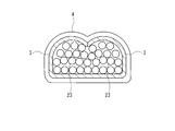
- FIG. 2 is a sectional view taken along line AA in FIG. 1. It is a figure for demonstrating typically the corrosion test method in an Example.
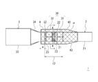
- FIG. 1 is a plan view showing an example of an automobile terminal crimped electric wire according to the present invention
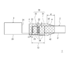
- FIG. 2 is a side view of FIG. 1
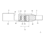
- FIG. 3 is a crevice corrosion between the connection terminal and the resin coating portion of FIG.
- FIG. 4 is a cross-sectional view taken along line AA of FIG. 2, the upper side in FIG. 2 is the upper surface side, the lower side is the bottom surface side, and the upper and lower sides in FIG. 1 are the side surfaces.
- a terminal crimped electric wire for automobiles (hereinafter also referred to as a terminal crimped electric wire) 1 of the present invention has a connection terminal 3 made of a copper-based material crimped to the end of an aluminum electric wire 2. And has a crimping portion 12. Furthermore, a resin-coated portion 4 made of resin is formed on the crimping portion 12 of the terminal crimping electric wire 1.
- FIGS. 1 to 3 show the appearance of the terminal crimped electric wire 1. For convenience of explanation, the region of the resin coating portion 4 is hatched, and each member in the lower layer is seen through the resin coating portion 4. Show.
- the aluminum electric wire 2 includes an insulating covering portion 21 in which a plurality of aluminum conductor wires 23 are covered with an insulator, and a conductor wire portion 22 in which the aluminum conductor wires 23 are exposed by peeling off the terminal insulator.
- connection terminal 3 shown in FIG. 1 and FIG. 2 is one in which tin plating is formed on the surface of a copper alloy.
- the connection terminal 3 is formed into a terminal shape by punching a flat tin-plated copper alloy into a predetermined shape and then bending it with a press. Therefore, the cut surface 34 formed by cutting in the punching process is in a state where it is not tin-plated.
- the connection terminal 3 shown in FIGS. 1 and 2 has an end surface formed as a cut surface 34.
- the connection terminal 3 includes a caulking portion 30 that is crimped to the aluminum electric wire 2 and an electrical contact portion 33 that is connected to another terminal.
- the caulking portion 30 includes a wire barrel 32 for caulking the conductor wire portion 22 of the aluminum electric wire 2, and an insulation barrel 31 for caulking the insulating coating portion 21 of the aluminum electric wire 2 at a predetermined distance from the wire barrel 32.
- the bottom surface of the caulking portion 30 is integrally formed by connecting the insulation barrel portion 31 and the wire barrel portion 32. In the state after the caulking portion 30 of the connection terminal 3 is caulked, a gap is formed between the side surface and the upper surface between the insulation barrel portion 31 and the wire barrel portion 32.
- the electrical contact portion 33 is female and is formed in a box shape into which a male connection terminal (not shown) can be fitted.
- the terminal crimped electric wire 1 has an insulation barrel 31 crimped on the insulation coating portion 21 of the aluminum electric wire 2 and a wire barrel 32 crimped on the conductor wire portion 22 of the aluminum electric wire 2.
- the crimping portion 12 is formed.
- a resin coating portion 4 made of resin is formed on the crimping portion 12 so as to cover the entire periphery of the crimping portion 12.
- the “crimping portion 12” is a portion corresponding to the caulking portion 30 in which the insulation barrel 31 and the wire barrel 32 are crimped and crimped to the aluminum electric wire. That is, as shown in FIGS. 1 and 2, this is a portion from the front end of the aluminum conductor wire 23 to the rear end of the insulation barrel 31.
- the longitudinal direction of the terminal crimped electric wire 1 is referred to as the front-rear direction, and the connection side with the other terminals is referred to as the front.
- the “whole circumference” of the crimping portion 12 means the front end portion of the aluminum conductor wire 23 and the outer surface of the barrel of the insulation barrel 31 or the wire barrel 32 in addition to the circumference in the side surface direction of the crimping portion. It is a part including the end surface in the front-rear direction of the barrel (a cut surface cut by punching) and the like. That is, the resin coating portion 4 is formed so as to cover the outer peripheral surface in a long range in the front-rear direction with respect to the crimping portion 12.
- a part of the insulating coating part and a part of the aluminum conductor wire 23 are exposed from the gap between the upper surface and the side surface between the insulation barrel 31 and the wire barrel 32. There are portions that are not covered by the 23 connection terminals. Further, the end of the aluminum conductor wire 23 protrudes from the front end of the wire barrel 32 to the electrical contact portion 33 side. The portions of the aluminum conductor wires 23 that are not covered by the connection terminals are all covered with the resin of the resin coating portion 4 so that the aluminum conductor wires 23 are not exposed to the outside.
- the resin-coated portion 4 made of resin is formed on the crimping portion 12 and the entire periphery of the crimping portion 12 is covered with a resin film, rainwater or the like is prevented from entering the crimping portion 12. Since the resin coating portion 4 is formed so as to cover the outer peripheral surface in a long range before and after the pressure bonding portion 12 and covers the entire periphery of the pressure bonding portion 12, a corrosion factor enters the pressure bonding portion 12 as described later. This can be prevented for a long time. In particular, as shown in FIG. 3, even when the crevice corrosion 41 proceeds in the gap between the connection terminal 3 and the resin coating portion 4, the crevice corrosion 41 does not contact the connection terminal 3 and the aluminum conductor wire 23. Can be prevented for a long time. That is, corrosion of the aluminum conductor wire 23 can be prevented for a long period of time, and the terminal crimped electric wire 1 having stable corrosion resistance can be obtained.
- connection terminal 3 tin corrosion occurs and tin elutes where the resin coating 4 is not formed. Then, the dissimilar metal contact part of tin and copper is exposed. When this copper and tin dissimilar metal contact portion is exposed to water, corrosion of the electrically base tin remarkably proceeds and the corrosion reaches the resin coating portion 4.
- the crevice corrosion 41 proceeds in the gap between the electrical contact portion 33 of the connection terminal 3 and the resin coating portion 4, and the crevice corrosion 41 eventually reaches the dissimilar metal contact portion where the connection terminal 3 and the aluminum conductor wire 23 contact. There is. When the crevice corrosion 41 reaches the dissimilar metal contact portion where the connection terminal 3 and the aluminum conductor wire 23 come into contact with each other, the corrosion of the aluminum conductor wire 23 proceeds remarkably. In particular, since the connection terminal 3 has a dissimilar metal contact portion where the cut surface 34 from which copper is exposed from the beginning and the surface tin contact each other, the influence of corrosion generated from the cut surface 34 is great.
- the resin coating portion 4 has a length a from the tip of the aluminum conductor wire 23 to the tip of the resin coating portion 4 of 0.3 mm or more, more preferably 1.0 mm or more. It is preferable to be formed as described above. When formed in this way, the length from the tip of the aluminum conductor wire to the tip of the resin coating portion becomes sufficiently long, and crevice corrosion that progresses between the resin coating portion 4 and the connection terminal 3 is caused by the aluminum conductor wire. It becomes difficult to reach the dissimilar metal contact part of 23 and the connection terminal 3.
- the resin coating portion 4 is formed so that the thickness of the portion covering the aluminum conductor wire 23 (reference numeral b in FIG. 2) is 0.01 mm or more, the surface of the resin coating portion 4 is scratched. It is easy to prevent the corrosion factor from entering the resin coating 4 and coming into contact with the aluminum conductor wire 23 even when a fine defect occurs. Furthermore, when the resin coating portion 4 is formed so that the thickness of the portion covering the aluminum conductor wire 23 is 0.1 mm or more, even when a larger scratch is applied, the resin coating portion 4 enters the resin coating portion of the corrosion factor. Can be prevented, and corrosion of the automobile terminal crimped electric wire 1 can be more effectively prevented.
- the resin coating portion 4 when the resin coating portion 4 is formed so that the thickness of the portion (reference symbol c in FIG. 2) covering the cut surface of the connection terminal 3 is 0.01 mm or more, the resin coating portion 4 is formed on the surface of the resin coating portion 4. Even when a fine defect such as a scratch occurs, it is easy to prevent a corrosion factor from entering the resin coating portion and coming into contact with the cut surface of the connection terminal 3. Furthermore, if the resin coating portion 4 is formed so that the thickness of the portion covering the cut surface of the connection terminal 3 is 0.1 mm or more, the resin coating of the corrosive factor can be obtained even when there is a larger scratch. The entry into the portion 4 can be prevented, and corrosion of the terminal crimped electric wire 1 can be more effectively prevented.
- the resin coating portion 4 has a taper portion 42 that is gradually tapered toward the aluminum electric wire 2 side at the rear end portion.
- the taper portion 42 is formed on the insulating coating portion 21.
- the resin coating of the resin coating portion 4 is hardly peeled off from the aluminum wire 3 even when the terminal crimped electric wire 1 is bent.
- the corrosion factor can be prevented from entering through the gap between the resin coating portion 4 and the aluminum electric wire 3, and the corrosion resistance of the aluminum conductor wire can be maintained.
- the rising angle ⁇ of the taper portion 42 is 45 ° or less, it is possible to more effectively prevent the resin film of the resin coating portion 4 from being peeled off from the aluminum electric wire 3.
- the rising angle ⁇ of the taper portion 42 is 30 ° or less, it is possible to prevent the resin film of the resin coating portion from being peeled off from the aluminum electric wire even when the taper portion 42 is bent more repeatedly or repeatedly.
- the resin coating portion 4 is peeled off to the terminal crimping portion even if the resin film of the resin coating portion 4 is somewhat peeled off from the aluminum electric wire 3. This makes it easy to prevent corrosion factors from entering the terminal crimping part. That is, stable anticorrosive properties can be exhibited. If the length is 2 mm or more, it is possible to more effectively prevent the corrosion factor from entering the terminal crimping portion.
- the resin-coated portion 4 can be formed by a method in which a terminal crimped electric wire is put in a suitable mold and the resin is injection-molded, or a molten resin is dripped and formed in a suitable place.
- an appropriate mold is used to control the length from the tip of the aluminum conductor wire to the tip of the resin coating, the thickness of the resin coating, the taper length and the angle of the resin coating. It is possible to use a method such as injection molding by using and using a method, or a method in which a molten resin is dripped in a large amount and solidified and then an excess portion is scraped off.
- the resin coating portion 4 is formed of a material mainly composed of a thermoplastic polyamide resin.
- the thermoplastic polyamide resin is more preferably composed of a combination of dimer acid and / or dicarboxylic acid and diamine. In this case, the balance of physical properties such as superposition tensile shear strength, elongation rate, water absorption rate, melt viscosity, etc. is good, and the balance between applicability and anticorrosion performance is excellent.
- the resin coating portion 4 may be composed of a thermoplastic polyamide resin alone or may be a mixture of two or more thermoplastic polyamide resins. Furthermore, if necessary, additives, other polymers, and the like may be mixed as long as the physical properties are not impaired.
- the additive is not particularly limited as long as it is an additive generally used for resin molding materials.
- inorganic fillers antioxidants, metal deactivators (copper damage inhibitors), UV absorbers, UV masking agents, flame retardant aids, processing aids (lubricants, waxes, etc.), Examples thereof include carbon and other coloring pigments.
- the resin coating 4 can be cross-linked as necessary for the purpose of increasing heat resistance and mechanical strength.
- the means of crosslinking such as thermal crosslinking, chemical crosslinking, silane crosslinking, electron beam crosslinking, and ultraviolet crosslinking.
- thermal crosslinking chemical crosslinking
- silane crosslinking silane crosslinking
- electron beam crosslinking electron beam crosslinking
- ultraviolet crosslinking what is necessary is just to perform the bridge
- the material forming the resin coating portion 4 has an overlap tensile shear strength of aluminum measured in accordance with JIS K6850 of 6 N / mm 2 or more.
- JIS K6850 Adhesive-Tensile Shear Adhesive Tensile Shear Bond Strength Test Method
- an Al plate is used as the rigid adherend, and the above-described material is used as an adhesive layer sandwiched between the Al plates, thereby producing a test piece.
- the overlapping tensile shear strength is preferably 7 N / mm 2 or more, more preferably 8 N / mm 2 or more.
- the upper limit of the said overlap tensile shear strength is not specifically limited.
- the material forming the resin coating portion 4 has an elongation percentage (at room temperature of 24 ° C.) measured in accordance with ASTM D-1708 of 100% or more.
- the elongation is preferably 150% or more, and more preferably 200% or more.
- the upper limit of the elongation rate is not particularly limited.
- the material forming the resin coating portion 4 has a water absorption rate of 1.0% or less measured in accordance with JIS K7209.
- the said water absorption is a value measured by A method on the conditions of immersion period: 7 days, test piece shape: sheet shape.
- the resin When the water absorption rate exceeds 1.0%, the resin easily absorbs water depending on the usage environment such as in a vehicle environment, and it is difficult to obtain a high anticorrosive effect.
- the water absorption rate is preferably 0.8% or less, and more preferably 0.5% or less.
- the minimum of the said water absorption is not specifically limited.
- the material which forms the resin coating part 4 is formed from a material which has a thermoplastic polyamide resin as a main component and each physical property of superposition tensile shear strength of aluminum, elongation rate, and water absorption in a specific range. Therefore, it can contribute to the improvement of anticorrosion performance also from a material surface.
- thermoplastic polyamide resin when the thermoplastic polyamide resin is composed of a combination of dimer acid and / or dicarboxylic acid and diamine, the balance of physical properties such as overlap tensile shear strength, elongation rate, water absorption rate, melt viscosity, etc. is good. It is excellent in the balance of the coating property at the time of formation of the resin coating portion 4 and the anticorrosion performance after the formation of the resin coating portion 4.
- Example 1 (Sample Nos. 1 to 16)
- the connection terminal 3 of the terminal crimped electric wire 1 is a 090 female connection terminal
- the aluminum electric wire 2 is a 0.75 mm 2 or 2.5 mm 2 size aluminum electric wire
- the resin that forms the resin coating 4 is a polyamide resin (manufactured by Henkel, “Macromelt 6202 "), the length a from the tip of the aluminum conductor wire 23 in FIG.
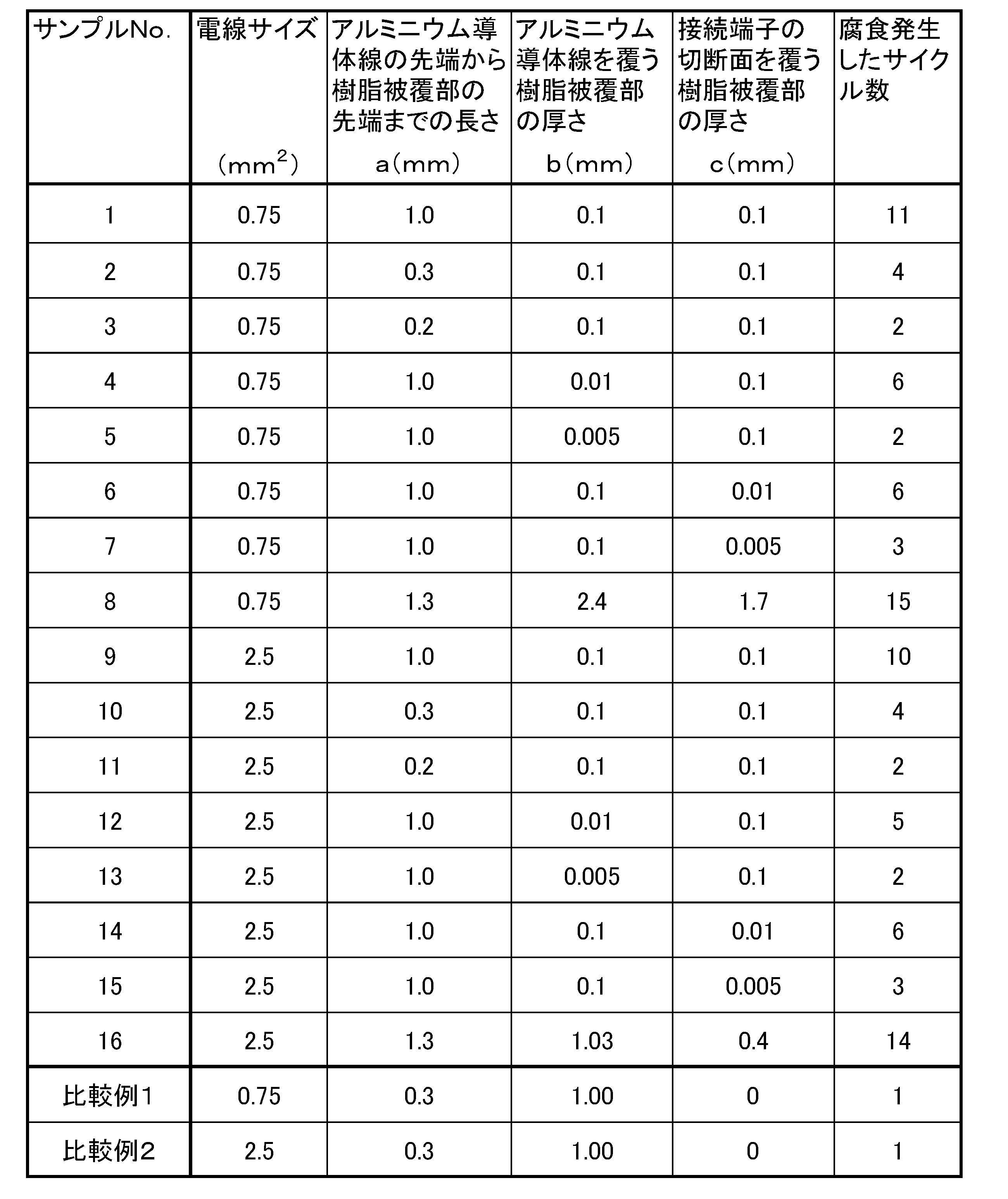
- Comparative Examples 1 and 2 For comparison, the resin-coated portion was formed only on the conductor wire portion of the crimping portion, but the terminal crimped electric wires of Comparative Examples 1 and 2 were the same as in the above example except that the cut surface was not covered with resin. And a corrosion test was conducted. The results of the corrosion tests of Comparative Examples 1 and 2 are shown in Table 1.
- the resin coating portion 4 covers the entire periphery of the crimping portion 12.
- the terminal crimped electric wires of Examples 1 to 16 formed in the above can withstand a corrosive environment for a long time.
- the crevice corrosion 41 becomes difficult to reach the dissimilar metal contact part of the aluminum conductor wire 23 and the connection terminal 3 by lengthening the length from the front-end
- Example 2 (Sample Nos. 17 to 30) Next, a bending test was performed on the terminal crimped electric wire 1 (No. 29 and 30 did not have a tapered portion) having a tapered portion at the rear end portion of the resin coated portion 4, and the aluminum electric wire 2 and the resin coated portion 4. The difficulty of peeling of the resin film was investigated. The length of the tapered portion is d, and the rising angle of the tapered portion is ⁇ . Hold the part 3cm behind the rear end of the insulation barrel 31 and the electrical contact portion 33 of the connection terminal 3, bend 90 ° in the direction of the crimping surface, and then bend 90 ° in the opposite direction. Then, it was examined whether or not the resin coating of the resin coating portion 4 reaching the insulation barrel 31 was peeled off.
- the length a from the tip of the aluminum conductor wire 23 to the tip of the resin coating portion 4 is 1 mm
- the thickness b of the resin coating portion covering the upper side of the conductor wire portion 22 was 0.1 mm
- the thickness c of the resin coating on the cut surface of the terminal was 0.1 mm.
- Example 3 Next, the anticorrosion performance was evaluated from the material aspect.
- the polyvinyl chloride composition obtained above was placed in the vicinity of a conductor group (cross-sectional area 0.75 mm 2 ) made of an aluminum alloy twisted wire in which seven aluminum alloy wires were twisted together. It was extrusion coated with a thickness of 28 mm. This produced the aluminum electric wire (PVC electric wire).
- Example No. 31 Thermoplastic polyamide resin (A) [manufactured by Henkel Japan KK, "Macromelt (registered trademark) 6801"] (Sample No. 32) Thermoplastic polyamide resin (B) [manufactured by Henkel Japan KK, "Macromelt (registered trademark) JP116"] (Sample No.
- the prepared terminal crimping electric wire 100 is connected to the + pole of the 12V power source 200, and the pure copper plate 300 (width 1 cm ⁇ length 2 cm ⁇ thickness 1 mm) is connected to the minus pole of the 12V power source 200,
- the caulked portion between the conductor group of the electric wire 100 and the terminal fitting and the pure copper plate 300 were immersed in 300 cc of a 5% NaCl 5% aqueous solution 400 and energized at 12 V for 2 minutes.
- ICP emission analysis of NaCl 5% aqueous solution 400 was performed, and the elution amount of aluminum ions from the conductor group of the terminal crimped electric wire 100 was measured.
- the case where the elution amount was less than 0.1 ppm was designated as “ ⁇ ”, and the case where the elution amount was 0.1 ppm or more was designated as “x”.
- the resin coating portion is formed of a material whose overlap tensile shear strength and water absorption rate are outside the limits of the present invention. Therefore, the adhesiveness is poor, water is easily absorbed, and the anticorrosion performance is inferior.
- the resin-coated portion is formed of a material whose overlap tensile shear strength and elongation rate are outside the limits of the present invention. Therefore, the adhesiveness is poor and the anticorrosion performance is inferior due to water immersion due to cracking.
- the resin coating portion is formed of a material in which all of the overlap tensile shear strength, the elongation rate, and the water absorption rate are out of the scope of the present invention. Therefore, the adhesiveness is poor, it is easy to absorb water, there is also water immersion due to cracking, and the anticorrosion performance is inferior.
- the resin coating portion is formed of a material within the ranges of the overlapping tensile shear strength, elongation rate, and water absorption rate specified in the present invention. Therefore, it can be sufficiently adhered to the electrical connection portion and water absorption can be prevented. In addition, it is excellent in applicability as compared with grease and the like, and is less likely to be cracked due to contraction due to cooling after application of the material. As a result, excellent anticorrosion performance can be exhibited. Therefore, according to the material of this invention, it has confirmed that it could contribute to the improvement of anticorrosion performance also from a material surface.
Landscapes
- Connections Effected By Soldering, Adhesion, Or Permanent Deformation (AREA)
Abstract
Description
実施例1(サンプルNo.1~16)
端子圧着電線1の接続端子3に090雌型接続端子、アルミニウム電線2に0.75mm2または2.5mm2サイズのアルミニウム電線、樹脂被覆部4を形成する樹脂にポリアミド樹脂(ヘンケル社製、「マクロメルト6202」)を用い、図1中のアルミニウム導体線23の先端から樹脂被覆部4の先端までの長さa、導体線部22の上側を覆う樹脂被覆部の厚さb、および端子の切断面上の樹脂被覆部の厚さcを様々に変えた端子圧着電線のサンプル1~16を作製し、腐食試験(JIS C 0023)を行なった。腐食試験は、試験時間を24時間とし、塩水噴霧装置から取り出し後、目視による外観観察により腐食発生の有無を確認する。これを1サイクルとし、腐食の発生が無い場合、繰り返し試験を行なった。腐食試験の結果を、腐食発生したサイクル数として、表1に示した。
比較のために、圧着部の導体線部のみに樹脂被覆部を形成したが、切断面の上を樹脂で覆わなかった以外は上記実施例と同様にして、比較例1、2の端子圧着電線を作製し、腐食試験を行った。比較例1、2の腐食試験の結果を表1に示した。
次に、樹脂被覆部4の後端部分に、テーパ部を有する端子圧着電線1(No.29、30はテーパ部を設けなかった。)について曲げ試験を行ない、アルミニウム電線2と樹脂被覆部4の樹脂皮膜の剥がれ難さを調べた。テーパ部の長さをd、テーパ部立ち上がり角度をαとする。インシュレーションバレル31の後端から3cm後ろの箇所と、接続端子3の電気接触部33を持ち、圧着面方向に90°に曲げ、その後逆方向に90°に曲げることを1回とし、何回でインシュレーションバレル31に到達する樹脂被覆部4の樹脂皮膜の剥がれが生じるかを調べた。樹脂皮膜の剥がれの有無の確認は目視観察で行った。このとき、サンプル17~30の樹脂被覆部4において、アルミニウム導体線23の先端から樹脂被覆部4の先端までの長さaは1mm、導体線部22の上側を覆う樹脂被覆部の厚さbは0.1mm、および端子の切断面上の樹脂被覆部の厚さcは0.1mmとした。

次に、材料面から防食性能を評価した。
ポリ塩化ビニル(重合度1300)100質量部に対して、可塑剤としてジイソノニルフタレート40質量部、充填剤として重炭酸カルシウム20質量部、安定剤としてカルシウム亜鉛系安定剤5質量部をオープンロールにより180℃で混合し、ペレタイザーにてペレット状に成形することにより、ポリ塩化ビニル組成物を調製した。
上記作製したアルミニウム電線の端末を皮剥して導体群を露出させた後、自動車用として汎用されている黄銅製のオス形状の端子金具(タブ幅0.64mm、導体群のかしめ部及び被覆部のかしめ部を有する)をアルミニウム電線の端末にかしめ圧着した。
熱可塑性ポリアミド樹脂(A)[ヘンケルジャパン(株)製、「マクロメルト(登録商標)6801」]
(サンプルNo.32)
熱可塑性ポリアミド樹脂(B)[ヘンケルジャパン(株)製、「マクロメルト(登録商標)JP116」]
(サンプルNo.33)
熱可塑性ポリアミド樹脂(C)[ヘンケルジャパン(株)製、「マクロメルト(登録商標)6301」]
(比較例3)
熱可塑性ポリアミド樹脂(a)[ヘンケルジャパン(株)製、「マクロメルト(登録商標)6217」]
(比較例4)
熱可塑性ポリアミド樹脂(b)[ヘンケルジャパン(株)製、「マクロメルト(登録商標)6030」]
(比較例5)
熱可塑性ポリアミド樹脂(c)[ヘンケルジャパン(株)製、「マクロメルト(登録商標)6880」]
各種の樹脂被覆部を形成した端子圧着電線を用い、ひび割れの有無の確認、防食性能の評価を以下のようにして行った。
各材料を塗布後、大気中に1日間放置し、ひび割れを顕微鏡を用いて目視観察した。ひび割れが見られなかった場合を○、ひび割れが見られた場合を×とした。
図5に示すように、作製した端子圧着電線100を12V電源200の+極につなぐとともに、純銅板300(幅1cm×長さ2cm×厚み1mm)を12V電源200の-極につなぎ、端子圧着電線100の導体群と端子金具とのかしめ部および純銅板300を300ccのNaCl5%水溶液400に浸漬し、12Vで2分間通電した。通電後、NaCl5%水溶液400のICP発光分析を行ない、端子圧着電線100の導体群からのアルミニウムイオンの溶出量を測定した。溶出量が0.1ppm未満であった場合を「○」とし、溶出量が0.1ppm以上であった場合を「×」とした。

Claims (13)
- アルミニウム導体線が絶縁体で覆われているアルミニウム電線の端末に、前記アルミニウム電線に圧着されるかしめ部と他の端子と接続するための電気接触部とを有する銅系材料からなる接続端子が圧着されているとともに、前記アルミニウム電線と前記接続端子の圧着部に樹脂による樹脂被覆部が形成された自動車用端子圧着電線において、
前記樹脂被覆部は、前記圧着部の全周囲を覆うように形成されており、
前記樹脂被覆部は、熱可塑性ポリアミド樹脂を主成分とし、JIS K6850に準拠して測定されるアルミニウム同士の重ね合わせ引張せん断強度が6N/mm2以上、ASTM D-1708に準拠して測定される伸び率が100%以上、JIS K7209に準拠して測定される吸水率が1.0%以下である材料により形成されていることを特徴とする自動車用端子圧着電線。 - 前記熱可塑性ポリアミド樹脂は、ダイマー酸および/またはジカルボン酸とジアミンとの組み合わせより構成されていることを特徴とする請求項1に記載の自動車用端子圧着電線。
- 前記樹脂被覆部は、前記アルミニウム導体線の先端から前記樹脂被覆部の先端までの長さが0.3mm以上となるように形成されていることを特徴とする請求項1または2に記載の自動車用端子圧着電線。
- 前記樹脂被覆部は、前記アルミニウム導体線の先端から前記樹脂被覆部の先端までの長さが1.0mm以上となるように形成されていることを特徴とする請求項1または2に記載の自動車用端子圧着電線。
- 前記樹脂被覆部は、アルミニウム導体線を覆う部分の厚さが0.01mm以上となるように形成されていることを特徴とする請求項1~4のいずれか1項に記載の自動車用端子圧着電線。
- 前記樹脂被覆部は、アルミニウム導体線を覆う部分の厚さが0.1mm以上となるように形成されていることを特徴とする請求項1~4のいずれか1項に記載の自動車用端子圧着電線。
- 前記樹脂被覆部は、接続端子の切断面を覆う部分の厚さが0.01mm以上となるように形成されていることを特徴とする請求項1~6のいずれか1項に記載の自動車用端子圧着電線。
- 前期樹脂被覆部は、接続端子の切断面を覆う部分の厚さが0.1mm以上となるように形成されていることを特徴とする請求項1~6のいずれか1項に記載の自動車用端子圧着電線。
- 前記樹脂被覆部は、後端部分にアルミニウム電線側に向かって漸次先細るテーパ部を有することを特徴とする請求項1~8のいずれか1項に記載の自動車用端子圧着電線。
- 前記樹脂被覆部の前記テーパ部の立ち上がり角度は45°以下であることを特徴とする請求項9に記載の自動車用端子圧着電線。
- 前記樹脂被覆部の前記テーパ部の立ち上がり角度は30°以下であることを特徴とする請求項9に記載の自動車用端子圧着電線。
- 前記樹脂被覆部の前記テーパ部の長さは1mm以上であることを特徴とする請求項9~11のいずれか1項に記載の自動車用端子圧着電線。
- 前記樹脂被覆部の前記テーパ部の長さは2mm以上であることを特徴とする請求項9~11のいずれか1項に記載の自動車用端子圧着電線。
Priority Applications (3)
| Application Number | Priority Date | Filing Date | Title |
|---|---|---|---|
| CN2012800098634A CN103403967A (zh) | 2011-02-21 | 2012-02-21 | 机动车用端子压接电线 |
| DE112012000927.4T DE112012000927T8 (de) | 2011-02-21 | 2012-02-21 | Gecrimpter Anschlussdraht für Automobile |
| US13/978,653 US20130292173A1 (en) | 2011-02-21 | 2012-02-21 | Crimped terminal wire for automobile |
Applications Claiming Priority (2)
| Application Number | Priority Date | Filing Date | Title |
|---|---|---|---|
| JP2011034354A JP2012174447A (ja) | 2011-02-21 | 2011-02-21 | 自動車用端子圧着電線 |
| JP2011-034354 | 2011-02-21 |
Publications (1)
| Publication Number | Publication Date |
|---|---|
| WO2012115071A1 true WO2012115071A1 (ja) | 2012-08-30 |
Family
ID=46720848
Family Applications (1)
| Application Number | Title | Priority Date | Filing Date |
|---|---|---|---|
| PCT/JP2012/054040 Ceased WO2012115071A1 (ja) | 2011-02-21 | 2012-02-21 | 自動車用端子圧着電線 |
Country Status (5)
| Country | Link |
|---|---|
| US (1) | US20130292173A1 (ja) |
| JP (1) | JP2012174447A (ja) |
| CN (1) | CN103403967A (ja) |
| DE (1) | DE112012000927T8 (ja) |
| WO (1) | WO2012115071A1 (ja) |
Cited By (1)
| Publication number | Priority date | Publication date | Assignee | Title |
|---|---|---|---|---|
| CN111344905A (zh) * | 2017-10-25 | 2020-06-26 | 株式会社自动网络技术研究所 | 带端子电线及线束 |
Families Citing this family (15)
| Publication number | Priority date | Publication date | Assignee | Title |
|---|---|---|---|---|
| JP2012252900A (ja) * | 2011-06-03 | 2012-12-20 | Yazaki Corp | 接続端子及び接続端子の製造方法 |
| US9024191B2 (en) * | 2011-10-03 | 2015-05-05 | Commscope Technologies Llc | Strain relief for connector and cable interconnection |
| DE112014003899T5 (de) * | 2013-08-26 | 2016-06-09 | Yazaki Corporation | Verbindungsstruktur eines Crimp-Anschlusses in Bezug auf einen Draht |
| CN203721972U (zh) * | 2013-12-11 | 2014-07-16 | 常州安费诺福洋通信设备有限公司 | 一种电缆组件与连接器的防水装置 |
| JP6426907B2 (ja) * | 2014-04-04 | 2018-11-21 | 矢崎総業株式会社 | 圧着端子と電線の接続構造 |
| JP6375921B2 (ja) * | 2014-12-11 | 2018-08-22 | 住友電装株式会社 | 端子金具付電線の端末止水構造 |
| JP6277983B2 (ja) * | 2015-03-20 | 2018-02-14 | 株式会社オートネットワーク技術研究所 | 端子固定治具及び熱収縮チューブ付電線の製造方法 |
| JP6489526B2 (ja) * | 2015-12-22 | 2019-03-27 | 矢崎総業株式会社 | 電線付き端子の製造方法 |
| JP6569127B2 (ja) * | 2016-02-02 | 2019-09-04 | 株式会社オートネットワーク技術研究所 | 金属板と合成樹脂材との固定構造、及びこれを有する配線部材 |
| JP2017195137A (ja) | 2016-04-22 | 2017-10-26 | 株式会社オートネットワーク技術研究所 | 端子付き被覆電線およびワイヤーハーネス |
| CN111194508A (zh) * | 2017-10-25 | 2020-05-22 | 株式会社自动网络技术研究所 | 带端子电线和线束 |
| JP6856138B2 (ja) * | 2017-10-25 | 2021-04-07 | 株式会社オートネットワーク技術研究所 | 端子付き電線およびワイヤーハーネス |
| JP2020009601A (ja) * | 2018-07-06 | 2020-01-16 | 矢崎総業株式会社 | 端子付き電線及びその製造方法 |
| WO2020105153A1 (ja) * | 2018-11-21 | 2020-05-28 | 株式会社オートネットワーク技術研究所 | 端子付き電線 |
| US11358544B2 (en) * | 2020-03-18 | 2022-06-14 | Yazaki Corporation | Wire harness including internal pressure adjuster |
Citations (5)
| Publication number | Priority date | Publication date | Assignee | Title |
|---|---|---|---|---|
| JPS63221507A (ja) * | 1987-03-10 | 1988-09-14 | 住友スリ−エム株式会社 | 絶縁電線の防水処理構造 |
| JPH07263106A (ja) * | 1994-03-23 | 1995-10-13 | Toyota Motor Corp | ワイヤハーネス枝線分岐部の防水処理方法及びその加 工装置 |
| WO1999035206A1 (en) * | 1998-01-12 | 1999-07-15 | Sumitomo Electric Industries, Ltd. | Adhesive resin composition and heat-shrinkable articles made by using the same |
| JP2001167821A (ja) * | 1999-12-09 | 2001-06-22 | Yazaki Corp | 被覆電線の端末接続部およびその防水処理方法と装置 |
| JP2003297447A (ja) * | 2002-04-05 | 2003-10-17 | Furukawa Electric Co Ltd:The | 接続端子装置 |
Family Cites Families (4)
| Publication number | Priority date | Publication date | Assignee | Title |
|---|---|---|---|---|
| JP2001167640A (ja) * | 1999-12-09 | 2001-06-22 | Yazaki Corp | 被覆電線の端末接続部およびその防水処理装置 |
| US7663059B2 (en) * | 2008-02-21 | 2010-02-16 | Yazaki Corporation | Cap and manufacturing method of the cap |
| JP5255404B2 (ja) | 2008-10-31 | 2013-08-07 | 古河電気工業株式会社 | 異種金属からなる電線と端子の接続部及び接続方法 |
| US8502074B2 (en) * | 2010-11-23 | 2013-08-06 | Matcor, Inc. | Seal for anode connection to cable and method of use |
-
2011
- 2011-02-21 JP JP2011034354A patent/JP2012174447A/ja active Pending
-
2012
- 2012-02-21 WO PCT/JP2012/054040 patent/WO2012115071A1/ja not_active Ceased
- 2012-02-21 DE DE112012000927.4T patent/DE112012000927T8/de not_active Ceased
- 2012-02-21 US US13/978,653 patent/US20130292173A1/en not_active Abandoned
- 2012-02-21 CN CN2012800098634A patent/CN103403967A/zh active Pending
Patent Citations (5)
| Publication number | Priority date | Publication date | Assignee | Title |
|---|---|---|---|---|
| JPS63221507A (ja) * | 1987-03-10 | 1988-09-14 | 住友スリ−エム株式会社 | 絶縁電線の防水処理構造 |
| JPH07263106A (ja) * | 1994-03-23 | 1995-10-13 | Toyota Motor Corp | ワイヤハーネス枝線分岐部の防水処理方法及びその加 工装置 |
| WO1999035206A1 (en) * | 1998-01-12 | 1999-07-15 | Sumitomo Electric Industries, Ltd. | Adhesive resin composition and heat-shrinkable articles made by using the same |
| JP2001167821A (ja) * | 1999-12-09 | 2001-06-22 | Yazaki Corp | 被覆電線の端末接続部およびその防水処理方法と装置 |
| JP2003297447A (ja) * | 2002-04-05 | 2003-10-17 | Furukawa Electric Co Ltd:The | 接続端子装置 |
Cited By (2)
| Publication number | Priority date | Publication date | Assignee | Title |
|---|---|---|---|---|
| CN111344905A (zh) * | 2017-10-25 | 2020-06-26 | 株式会社自动网络技术研究所 | 带端子电线及线束 |
| CN111344905B (zh) * | 2017-10-25 | 2021-06-18 | 株式会社自动网络技术研究所 | 带端子电线及线束 |
Also Published As
| Publication number | Publication date |
|---|---|
| US20130292173A1 (en) | 2013-11-07 |
| CN103403967A (zh) | 2013-11-20 |
| DE112012000927T8 (de) | 2014-03-06 |
| DE112012000927T5 (de) | 2013-12-05 |
| JP2012174447A (ja) | 2012-09-10 |
Similar Documents
| Publication | Publication Date | Title |
|---|---|---|
| WO2012115071A1 (ja) | 自動車用端子圧着電線 | |
| JP5063750B2 (ja) | ワイヤーハーネスの端末構造 | |
| JP5095705B2 (ja) | 端子付き被覆電線およびワイヤーハーネス | |
| WO2012053275A1 (ja) | 自動車用端子圧着電線 | |
| JP5063751B2 (ja) | ワイヤーハーネスの端末構造 | |
| JP5565223B2 (ja) | 端子付き電線 | |
| WO2011096527A1 (ja) | 接続構造体 | |
| WO2011108525A1 (ja) | 防食剤、端子付き被覆電線およびワイヤーハーネス | |
| JP2012113963A (ja) | 端子付き電線 | |
| JP2012059671A (ja) | 端子付き電線 | |
| JP2013025910A (ja) | 自動車用端子圧着電線 | |
| JP2012174449A (ja) | 自動車用端子圧着電線 | |
| JP2012059665A (ja) | 端子付き電線 | |
| JP2013214439A (ja) | 端子付き被覆電線およびその製造方法、ならびにワイヤーハーネス | |
| JP5565224B2 (ja) | 端子付き電線 | |
| JP2012028154A (ja) | ワイヤーハーネスの端末構造 | |
| JP2012054170A (ja) | 端子圧着電線 | |
| WO2014132538A1 (ja) | 端子付き被覆電線及びワイヤーハーネス | |
| WO2013011846A1 (ja) | 防食剤、端子付き被覆電線およびワイヤーハーネス | |
| JP6260363B2 (ja) | 端子付き被覆電線 | |
| JP2012256464A (ja) | 端子付電線 | |
| JP2013067847A (ja) | 防食剤、端子付き被覆電線及びワイヤーハーネス | |
| JP2015109168A (ja) | 端子付き被覆電線およびワイヤーハーネス | |
| JP2014110151A (ja) | 端子付き被覆電線、ワイヤーハーネス、および防食剤 |
Legal Events
| Date | Code | Title | Description |
|---|---|---|---|
| 121 | Ep: the epo has been informed by wipo that ep was designated in this application |
Ref document number: 12750150 Country of ref document: EP Kind code of ref document: A1 |
|
| WWE | Wipo information: entry into national phase |
Ref document number: 13978653 Country of ref document: US |
|
| WWE | Wipo information: entry into national phase |
Ref document number: 112012000927 Country of ref document: DE Ref document number: 1120120009274 Country of ref document: DE |
|
| 122 | Ep: pct application non-entry in european phase |
Ref document number: 12750150 Country of ref document: EP Kind code of ref document: A1 |