WO2012114440A1 - 車両用駆動装置の制御装置 - Google Patents
車両用駆動装置の制御装置 Download PDFInfo
- Publication number
- WO2012114440A1 WO2012114440A1 PCT/JP2011/053725 JP2011053725W WO2012114440A1 WO 2012114440 A1 WO2012114440 A1 WO 2012114440A1 JP 2011053725 W JP2011053725 W JP 2011053725W WO 2012114440 A1 WO2012114440 A1 WO 2012114440A1
- Authority
- WO
- WIPO (PCT)
- Prior art keywords
- engine
- shift
- torque
- speed
- sequential
- Prior art date
- Legal status (The legal status is an assumption and is not a legal conclusion. Google has not performed a legal analysis and makes no representation as to the accuracy of the status listed.)
- Ceased
Links
Images




Classifications
-
- B—PERFORMING OPERATIONS; TRANSPORTING
- B60—VEHICLES IN GENERAL
- B60W—CONJOINT CONTROL OF VEHICLE SUB-UNITS OF DIFFERENT TYPE OR DIFFERENT FUNCTION; CONTROL SYSTEMS SPECIALLY ADAPTED FOR HYBRID VEHICLES; ROAD VEHICLE DRIVE CONTROL SYSTEMS FOR PURPOSES NOT RELATED TO THE CONTROL OF A PARTICULAR SUB-UNIT
- B60W10/00—Conjoint control of vehicle sub-units of different type or different function
- B60W10/10—Conjoint control of vehicle sub-units of different type or different function including control of change-speed gearings
-
- B—PERFORMING OPERATIONS; TRANSPORTING
- B60—VEHICLES IN GENERAL
- B60W—CONJOINT CONTROL OF VEHICLE SUB-UNITS OF DIFFERENT TYPE OR DIFFERENT FUNCTION; CONTROL SYSTEMS SPECIALLY ADAPTED FOR HYBRID VEHICLES; ROAD VEHICLE DRIVE CONTROL SYSTEMS FOR PURPOSES NOT RELATED TO THE CONTROL OF A PARTICULAR SUB-UNIT
- B60W10/00—Conjoint control of vehicle sub-units of different type or different function
- B60W10/04—Conjoint control of vehicle sub-units of different type or different function including control of propulsion units
- B60W10/06—Conjoint control of vehicle sub-units of different type or different function including control of propulsion units including control of combustion engines
-
- B—PERFORMING OPERATIONS; TRANSPORTING
- B60—VEHICLES IN GENERAL
- B60K—ARRANGEMENT OR MOUNTING OF PROPULSION UNITS OR OF TRANSMISSIONS IN VEHICLES; ARRANGEMENT OR MOUNTING OF PLURAL DIVERSE PRIME-MOVERS IN VEHICLES; AUXILIARY DRIVES FOR VEHICLES; INSTRUMENTATION OR DASHBOARDS FOR VEHICLES; ARRANGEMENTS IN CONNECTION WITH COOLING, AIR INTAKE, GAS EXHAUST OR FUEL SUPPLY OF PROPULSION UNITS IN VEHICLES
- B60K6/00—Arrangement or mounting of plural diverse prime-movers for mutual or common propulsion, e.g. hybrid propulsion systems comprising electric motors and internal combustion engines
- B60K6/20—Arrangement or mounting of plural diverse prime-movers for mutual or common propulsion, e.g. hybrid propulsion systems comprising electric motors and internal combustion engines the prime-movers consisting of electric motors and internal combustion engines, e.g. HEVs
- B60K6/42—Arrangement or mounting of plural diverse prime-movers for mutual or common propulsion, e.g. hybrid propulsion systems comprising electric motors and internal combustion engines the prime-movers consisting of electric motors and internal combustion engines, e.g. HEVs characterised by the architecture of the hybrid electric vehicle
- B60K6/44—Series-parallel type
- B60K6/445—Differential gearing distribution type
-
- B—PERFORMING OPERATIONS; TRANSPORTING
- B60—VEHICLES IN GENERAL
- B60K—ARRANGEMENT OR MOUNTING OF PROPULSION UNITS OR OF TRANSMISSIONS IN VEHICLES; ARRANGEMENT OR MOUNTING OF PLURAL DIVERSE PRIME-MOVERS IN VEHICLES; AUXILIARY DRIVES FOR VEHICLES; INSTRUMENTATION OR DASHBOARDS FOR VEHICLES; ARRANGEMENTS IN CONNECTION WITH COOLING, AIR INTAKE, GAS EXHAUST OR FUEL SUPPLY OF PROPULSION UNITS IN VEHICLES
- B60K6/00—Arrangement or mounting of plural diverse prime-movers for mutual or common propulsion, e.g. hybrid propulsion systems comprising electric motors and internal combustion engines
- B60K6/20—Arrangement or mounting of plural diverse prime-movers for mutual or common propulsion, e.g. hybrid propulsion systems comprising electric motors and internal combustion engines the prime-movers consisting of electric motors and internal combustion engines, e.g. HEVs
- B60K6/42—Arrangement or mounting of plural diverse prime-movers for mutual or common propulsion, e.g. hybrid propulsion systems comprising electric motors and internal combustion engines the prime-movers consisting of electric motors and internal combustion engines, e.g. HEVs characterised by the architecture of the hybrid electric vehicle
- B60K6/48—Parallel type
- B60K6/485—Motor-assist type
-
- B—PERFORMING OPERATIONS; TRANSPORTING
- B60—VEHICLES IN GENERAL
- B60W—CONJOINT CONTROL OF VEHICLE SUB-UNITS OF DIFFERENT TYPE OR DIFFERENT FUNCTION; CONTROL SYSTEMS SPECIALLY ADAPTED FOR HYBRID VEHICLES; ROAD VEHICLE DRIVE CONTROL SYSTEMS FOR PURPOSES NOT RELATED TO THE CONTROL OF A PARTICULAR SUB-UNIT
- B60W10/00—Conjoint control of vehicle sub-units of different type or different function
- B60W10/04—Conjoint control of vehicle sub-units of different type or different function including control of propulsion units
- B60W10/08—Conjoint control of vehicle sub-units of different type or different function including control of propulsion units including control of electric propulsion units, e.g. motors or generators
-
- B—PERFORMING OPERATIONS; TRANSPORTING
- B60—VEHICLES IN GENERAL
- B60W—CONJOINT CONTROL OF VEHICLE SUB-UNITS OF DIFFERENT TYPE OR DIFFERENT FUNCTION; CONTROL SYSTEMS SPECIALLY ADAPTED FOR HYBRID VEHICLES; ROAD VEHICLE DRIVE CONTROL SYSTEMS FOR PURPOSES NOT RELATED TO THE CONTROL OF A PARTICULAR SUB-UNIT
- B60W20/00—Control systems specially adapted for hybrid vehicles
-
- B—PERFORMING OPERATIONS; TRANSPORTING
- B60—VEHICLES IN GENERAL
- B60W—CONJOINT CONTROL OF VEHICLE SUB-UNITS OF DIFFERENT TYPE OR DIFFERENT FUNCTION; CONTROL SYSTEMS SPECIALLY ADAPTED FOR HYBRID VEHICLES; ROAD VEHICLE DRIVE CONTROL SYSTEMS FOR PURPOSES NOT RELATED TO THE CONTROL OF A PARTICULAR SUB-UNIT
- B60W20/00—Control systems specially adapted for hybrid vehicles
- B60W20/30—Control strategies involving selection of transmission gear ratio
-
- B—PERFORMING OPERATIONS; TRANSPORTING
- B60—VEHICLES IN GENERAL
- B60W—CONJOINT CONTROL OF VEHICLE SUB-UNITS OF DIFFERENT TYPE OR DIFFERENT FUNCTION; CONTROL SYSTEMS SPECIALLY ADAPTED FOR HYBRID VEHICLES; ROAD VEHICLE DRIVE CONTROL SYSTEMS FOR PURPOSES NOT RELATED TO THE CONTROL OF A PARTICULAR SUB-UNIT
- B60W20/00—Control systems specially adapted for hybrid vehicles
- B60W20/40—Controlling the engagement or disengagement of prime movers, e.g. for transition between prime movers
-
- B—PERFORMING OPERATIONS; TRANSPORTING
- B60—VEHICLES IN GENERAL
- B60W—CONJOINT CONTROL OF VEHICLE SUB-UNITS OF DIFFERENT TYPE OR DIFFERENT FUNCTION; CONTROL SYSTEMS SPECIALLY ADAPTED FOR HYBRID VEHICLES; ROAD VEHICLE DRIVE CONTROL SYSTEMS FOR PURPOSES NOT RELATED TO THE CONTROL OF A PARTICULAR SUB-UNIT
- B60W30/00—Purposes of road vehicle drive control systems not related to the control of a particular sub-unit, e.g. of systems using conjoint control of vehicle sub-units
- B60W30/18—Propelling the vehicle
- B60W30/19—Improvement of gear change, e.g. by synchronisation or smoothing gear shift
-
- B—PERFORMING OPERATIONS; TRANSPORTING
- B60—VEHICLES IN GENERAL
- B60W—CONJOINT CONTROL OF VEHICLE SUB-UNITS OF DIFFERENT TYPE OR DIFFERENT FUNCTION; CONTROL SYSTEMS SPECIALLY ADAPTED FOR HYBRID VEHICLES; ROAD VEHICLE DRIVE CONTROL SYSTEMS FOR PURPOSES NOT RELATED TO THE CONTROL OF A PARTICULAR SUB-UNIT
- B60W2540/00—Input parameters relating to occupants
- B60W2540/16—Ratio selector position
- B60W2540/165—Rate of change
-
- B—PERFORMING OPERATIONS; TRANSPORTING
- B60—VEHICLES IN GENERAL
- B60W—CONJOINT CONTROL OF VEHICLE SUB-UNITS OF DIFFERENT TYPE OR DIFFERENT FUNCTION; CONTROL SYSTEMS SPECIALLY ADAPTED FOR HYBRID VEHICLES; ROAD VEHICLE DRIVE CONTROL SYSTEMS FOR PURPOSES NOT RELATED TO THE CONTROL OF A PARTICULAR SUB-UNIT
- B60W2710/00—Output or target parameters relating to a particular sub-units
- B60W2710/06—Combustion engines, Gas turbines
- B60W2710/0644—Engine speed
-
- B—PERFORMING OPERATIONS; TRANSPORTING
- B60—VEHICLES IN GENERAL
- B60W—CONJOINT CONTROL OF VEHICLE SUB-UNITS OF DIFFERENT TYPE OR DIFFERENT FUNCTION; CONTROL SYSTEMS SPECIALLY ADAPTED FOR HYBRID VEHICLES; ROAD VEHICLE DRIVE CONTROL SYSTEMS FOR PURPOSES NOT RELATED TO THE CONTROL OF A PARTICULAR SUB-UNIT
- B60W2710/00—Output or target parameters relating to a particular sub-units
- B60W2710/06—Combustion engines, Gas turbines
- B60W2710/0666—Engine torque
-
- B—PERFORMING OPERATIONS; TRANSPORTING
- B60—VEHICLES IN GENERAL
- B60W—CONJOINT CONTROL OF VEHICLE SUB-UNITS OF DIFFERENT TYPE OR DIFFERENT FUNCTION; CONTROL SYSTEMS SPECIALLY ADAPTED FOR HYBRID VEHICLES; ROAD VEHICLE DRIVE CONTROL SYSTEMS FOR PURPOSES NOT RELATED TO THE CONTROL OF A PARTICULAR SUB-UNIT
- B60W2710/00—Output or target parameters relating to a particular sub-units
- B60W2710/08—Electric propulsion units
- B60W2710/081—Speed
-
- B—PERFORMING OPERATIONS; TRANSPORTING
- B60—VEHICLES IN GENERAL
- B60W—CONJOINT CONTROL OF VEHICLE SUB-UNITS OF DIFFERENT TYPE OR DIFFERENT FUNCTION; CONTROL SYSTEMS SPECIALLY ADAPTED FOR HYBRID VEHICLES; ROAD VEHICLE DRIVE CONTROL SYSTEMS FOR PURPOSES NOT RELATED TO THE CONTROL OF A PARTICULAR SUB-UNIT
- B60W2710/00—Output or target parameters relating to a particular sub-units
- B60W2710/08—Electric propulsion units
- B60W2710/083—Torque
-
- B—PERFORMING OPERATIONS; TRANSPORTING
- B60—VEHICLES IN GENERAL
- B60W—CONJOINT CONTROL OF VEHICLE SUB-UNITS OF DIFFERENT TYPE OR DIFFERENT FUNCTION; CONTROL SYSTEMS SPECIALLY ADAPTED FOR HYBRID VEHICLES; ROAD VEHICLE DRIVE CONTROL SYSTEMS FOR PURPOSES NOT RELATED TO THE CONTROL OF A PARTICULAR SUB-UNIT
- B60W30/00—Purposes of road vehicle drive control systems not related to the control of a particular sub-unit, e.g. of systems using conjoint control of vehicle sub-units
- B60W30/18—Propelling the vehicle
- B60W30/188—Controlling power parameters of the driveline, e.g. determining the required power
-
- Y—GENERAL TAGGING OF NEW TECHNOLOGICAL DEVELOPMENTS; GENERAL TAGGING OF CROSS-SECTIONAL TECHNOLOGIES SPANNING OVER SEVERAL SECTIONS OF THE IPC; TECHNICAL SUBJECTS COVERED BY FORMER USPC CROSS-REFERENCE ART COLLECTIONS [XRACs] AND DIGESTS
- Y02—TECHNOLOGIES OR APPLICATIONS FOR MITIGATION OR ADAPTATION AGAINST CLIMATE CHANGE
- Y02T—CLIMATE CHANGE MITIGATION TECHNOLOGIES RELATED TO TRANSPORTATION
- Y02T10/00—Road transport of goods or passengers
- Y02T10/60—Other road transportation technologies with climate change mitigation effect
- Y02T10/62—Hybrid vehicles
-
- Y—GENERAL TAGGING OF NEW TECHNOLOGICAL DEVELOPMENTS; GENERAL TAGGING OF CROSS-SECTIONAL TECHNOLOGIES SPANNING OVER SEVERAL SECTIONS OF THE IPC; TECHNICAL SUBJECTS COVERED BY FORMER USPC CROSS-REFERENCE ART COLLECTIONS [XRACs] AND DIGESTS
- Y02—TECHNOLOGIES OR APPLICATIONS FOR MITIGATION OR ADAPTATION AGAINST CLIMATE CHANGE
- Y02T—CLIMATE CHANGE MITIGATION TECHNOLOGIES RELATED TO TRANSPORTATION
- Y02T10/00—Road transport of goods or passengers
- Y02T10/60—Other road transportation technologies with climate change mitigation effect
- Y02T10/72—Electric energy management in electromobility
-
- Y—GENERAL TAGGING OF NEW TECHNOLOGICAL DEVELOPMENTS; GENERAL TAGGING OF CROSS-SECTIONAL TECHNOLOGIES SPANNING OVER SEVERAL SECTIONS OF THE IPC; TECHNICAL SUBJECTS COVERED BY FORMER USPC CROSS-REFERENCE ART COLLECTIONS [XRACs] AND DIGESTS
- Y10—TECHNICAL SUBJECTS COVERED BY FORMER USPC
- Y10S—TECHNICAL SUBJECTS COVERED BY FORMER USPC CROSS-REFERENCE ART COLLECTIONS [XRACs] AND DIGESTS
- Y10S903/00—Hybrid electric vehicles, HEVS
- Y10S903/902—Prime movers comprising electrical and internal combustion motors
- Y10S903/903—Prime movers comprising electrical and internal combustion motors having energy storing means, e.g. battery, capacitor
- Y10S903/93—Conjoint control of different elements
Definitions
- the present invention relates to a technique for improving drivability in a vehicle including an engine and an electric motor.
- the present invention has been made against the background of the above circumstances.
- the object of the present invention is to provide a speed change mechanism that constitutes a part of a power transmission path between an engine and a drive wheel, and the rotational speed of the engine.
- An object of the present invention is to provide a control device for a vehicle drive device that can improve drivability in the sequential shift in a vehicle including an electric motor to be changed.
- the gist of the first invention for achieving the above object is as follows: (a) a transmission mechanism that constitutes a part of a power transmission path between the engine and the drive wheels, and the engine in the transmission process of the transmission mechanism; In a vehicle equipped with an electric motor capable of changing the rotational speed, at least one of the engine and the electric motor is responsible for a shift that discretely changes the rotational speed of the engine according to the operation of the driver. A control device for a vehicle drive device that changes the rotational speed of the engine by the generated torque, (b) In the discrete shift, the torque sharing ratio of the engine increases as the rotational speed change width of the engine increases. It is large.
- the sequential shift time required from the start to the end of the sequential shift which is the discrete shift, can be prevented from being increased due to the large change in the engine speed, and the driver's operation
- the response of the vehicle to the vehicle can be sufficiently secured. Accordingly, it is possible to improve drivability in the sequential shift (discrete shift).
- the drivability is a feeling of whether or not the response and smoothness of the vehicle in accordance with the will of the driver can be obtained. Improvement of drivability means that a driver or the like feels that the responsiveness and smoothness of the vehicle are good. The deterioration of drivability means that a driver or the like feels that the responsiveness or smoothness of the vehicle is poor.
- the subject matter of the second invention is a control device for a vehicle drive device according to the first invention, wherein (a) the vehicle is provided with a power storage device capable of transferring power to and from the motor; )
- the torque sharing ratio of the engine is larger as the restriction on the charging power or discharging power of the power storage device is larger.
- motor torque the torque of the motor
- engine torque the engine torque
- the gist of the third invention is a control device for a vehicle drive device according to the first invention or the second invention.
- the engine temperature decreases as the engine temperature decreases.
- the torque sharing ratio is large.
- the engine Since the change speed of the engine rotation speed can be sufficiently obtained by the torque, it is possible to suppress an increase in the sequential shift time. For example, when the engine is not warmed up sufficiently and the engine is at a low temperature, the rotational resistance of the engine increases. Therefore, in the third aspect of the invention, for example, the torque sharing ratio of the engine is greater when the engine is before completion of warm-up than after completion of warm-up.
- a fourth aspect of the invention is a control device for a vehicle drive device according to any one of the first to third inventions, wherein the rotational speed of the engine is changing at the discrete speed change. If the engine or the motor has insufficient torque and it is determined that the discrete shift will not end within a preset target shift time, the engine with the larger amount of torque shortage is determined. Alternatively, the torque sharing ratio of the electric motor is lowered during the change of the rotational speed of the engine than before the determination. In this way, the sequential shift is more reliably completed within the target shift time compared to the case where it is not determined whether or not the sequential shift (discrete shift) is completed within the target shift time. And drivability can be improved.
- the lack of torque of the engine or the electric motor is a lack of torque in the rotational speed change direction of the engine at the sequential shift. In other words, there is insufficient torque with the engine speed changing direction in the sequential shift as the positive direction.
- the gist of the fifth invention is (a) a speed change mechanism that constitutes a part of a power transmission path between the engine and the drive wheels, and the engine speed is changed in the speed change process of the speed change mechanism.
- a downshift that discretely increases the rotational speed of the engine according to a driver's operation in a vehicle equipped with an electric motor capable of being driven by torque generated by sharing at least one of the engine and the electric motor
- B In the discrete downshift, the greater the gear ratio of the transmission mechanism before the downshift, the greater the speed ratio before and after the downshift. The increase in the transmission ratio is large, and the torque sharing ratio of the engine is large.
- the torque sharing ratio of the engine in the sequential shift is determined based on a driving condition from a predetermined relationship.
- the travel conditions include the engine speed change width in the sequential shift, the limit value (upper limit value) for the charging power of the power storage device, the limit value (upper limit value) for the discharge power of the power storage device, and the Any or all of the engine temperature.
- the torque sharing ratio of the engine can be determined easily and appropriately before the start of sequential shift.
- a small limit value for the charging power means that the restriction for the charging power is large
- a small limit value for the discharging power means that the restriction for the discharging power is large.
- the sequential shift is a sequential down shift (discrete down shift) in which the rotational speed of the engine is increased more than before the start of the shift, and the vehicle is coasting.
- a sequential upshift (discrete upshift) in which the rotational speed of the engine is lower than before the start of the shift, and is performed during the acceleration operation of the vehicle. If it does in this way, the responsiveness can be improved in the sequential shift in which the driver particularly desires the responsiveness of the vehicle, and the drivability in the sequential shift can be effectively improved.
- the discrete shift in the first invention is limited to the discrete downshift. Further, the larger the increase amount of the gear ratio before and after the discrete downshift, the greater the engine speed change range. Accordingly, the first invention and the fifth invention have the same special technical feature that “the greater the change in the rotational speed of the engine, the greater the torque sharing ratio of the engine in the discrete speed change”. As such, they are linked to form a single general inventive concept.
- FIG. 1 is a skeleton diagram of Embodiment 1 for explaining a vehicle drive device to which the present invention is applied.
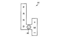
- FIG. 2 is a diagram illustrating an example of a shift operation device as a switching device that switches a plurality of types of shift positions by an artificial operation in the vehicle drive device of FIG. 1.
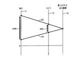
- FIG. 2 is a collinear diagram of the first embodiment for explaining a downshift of the first planetary gear device in sequential shift performed by the electronic control unit of the vehicle drive device of FIG. 1. It is the figure which illustrated the signal input into the electronic control apparatus which controls the vehicle drive device of FIG. 1, and the signal output from the electronic control apparatus, and has shown the principal part of the control function with which the electronic control apparatus was equipped.
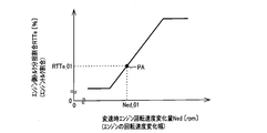
- FIG. 5 is an engine-side torque sharing ratio calculation map that is experimentally determined in advance for the electronic control unit of FIG. 4 to determine the engine-side torque sharing ratio based on the engine speed change amount during shifting.
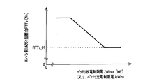
- FIG. 5 is a map for calculating an engine-side torque sharing ratio that is experimentally determined in advance for the electronic control unit of FIG. 4 to determine an engine-side torque sharing ratio based on battery discharge limit power.
- FIG. 5 is an engine-side torque sharing ratio calculation map that is experimentally determined in advance for the electronic control unit of FIG. 4 to determine the engine-side torque sharing ratio based on the engine water temperature.
- FIG. 5 is a flowchart of Example 1 for explaining a main part of a control operation of the electronic control device of FIG.
- FIG. 4 is a control operation for executing a sequential shift.
- FIG. FIG. 5 is a first time chart in the first embodiment for explaining the control operation of the electronic control device of FIG. 4, wherein the sequential shift downshift (sequential down shift) is performed during inertial traveling with the accelerator pedal released.
- FIG. 6 is a time chart for explaining torque control of the engine and the first electric motor in the sequential shift, taking as an example a broken case;
- FIG. 6 is a second time chart in the first embodiment for explaining the control operation of the electronic control device of FIG. 4, and the sequential shift upshift (sequential up) during the acceleration operation in the accelerator-on state where the accelerator pedal is depressed.
- FIG. 7 is a time chart for explaining torque control of the engine and the first electric motor in the sequential shift, taking as an example a case where a shift is performed.
- FIG. 6 is a third time chart in the first embodiment for explaining the control operation of the electronic control device of FIG. 4, and illustrates an example in which a downshift (sequential downshift) of a sequential shift is performed during the inertia traveling.
- FIG. 5 is a time chart for explaining torque control of the engine and the first electric motor when a shift delay is detected during the sequential shift.
- FIG. 13 is a collinear diagram of Embodiment 2 for describing a downshift of an automatic transmission included in the vehicle drive device of FIG. 12.
- FIG. 12 is a flowchart for explaining a main part of the control operation of the electronic control unit of FIG. 12, that is, a flowchart for explaining the control operation for executing the sequential shift.
- FIG. 13 is a second excerpt showing steps different from those in FIG.
- FIG. 13 is a time chart in the second embodiment for explaining the control operation of the electronic control device of FIG. 12, in a case where a downshift (sequential downshift) of a sequential shift is performed by the automatic transmission 112 during the inertia traveling. It is a time chart for demonstrating the torque control of the engine and driving
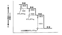
- FIG. 13 is a schematic diagram for explaining an example in which the engine-side torque sharing ratio is determined in advance by using, as a parameter, a shift stage before and after a sequential shift in the control executed by the electronic control unit of FIGS.
- FIG. 1 is a skeleton diagram for explaining a vehicle drive device 8 to which the present invention is applied.
- the vehicle drive device 8 includes an engine 14 that outputs driving power, and a vehicle power transmission device that is interposed between the engine 14 and drive wheels 40 (see FIG. 4). 10 (hereinafter referred to as “power transmission device 10”).
- the power transmission device 10 is a transaxle that transmits driving force from the engine 14 to the driving wheels 40.
- the power transmission device 10 outputs the output of the engine 14 in turn from the engine 14 side in a transaxle (T / A) case 12 (hereinafter referred to as “case 12”) as a non-rotating member attached to the vehicle body.
- T / A transaxle
- case 12 case 12
- a damper 16 that is operatively connected to a shaft 15 (for example, a crankshaft) and absorbs pulsation due to torque fluctuations from the engine 14, an input shaft 18 that is rotationally driven by the engine 14 via the damper 16, a first electric motor MG1 (Corresponding to the electric motor of the present invention), a first planetary gear device 20 that is a differential mechanism capable of continuously changing the differential state, a second planetary gear device 22 that functions as a reduction gear, and a drive wheel 40 is provided with a second electric motor MG2 that outputs driving power connected to the power transmission 40.
- a shaft 15 for example, a crankshaft
- a first electric motor MG1 Corresponding to the electric motor of the present invention
- a first planetary gear device 20 that is a differential mechanism capable of continuously changing the differential state
- a second planetary gear device 22 that functions as a reduction gear
- a drive wheel 40 is provided with a second electric motor MG2 that outputs driving power connected to the power transmission 40.
- the power transmission device 10 is, for example, placed in front of a front wheel drive, that is, an FF (front engine / front drive) type vehicle 6, and is preferably used to drive the drive wheels 40.
- the power of the engine 14 includes an output gear 24 as an output rotation member of the power transmission device 10 constituting one of the counter gear pairs 32, a counter gear pair 32, a final gear pair 34, a differential gear device (final gear device). It is transmitted to the pair of drive wheels 40 through the reduction gear 36 and the pair of axles 38 in order (see FIG. 4).
- the input shaft 18 and the engine 14 are operatively connected via the damper 16, and the output shaft 15 of the engine 14 is of course the output rotating member of the engine 14.
- the input shaft 18 also corresponds to the output rotating member of the engine 14.
- the engine 14 may be an internal combustion engine such as a gasoline engine for automobiles or a diesel engine, but is a gasoline engine for automobiles in this embodiment.
- the torque Te generated by the engine 14 is, for example, an electronic throttle valve opening / closing control of the engine 14, an ignition timing control of the engine 14, a valve timing control for controlling the opening / closing timings of the intake valve and the exhaust valve of the engine 14, or , Adjusted by a combination thereof.
- the both ends of the input shaft 18 are rotatably supported by ball bearings 26 and 28, and one end of the input shaft 18 is connected to the engine 14 via the damper 16 so that the input shaft 18 is rotated by the engine 14. Further, an oil pump 30 as a lubricating oil supply device is connected to the other end, and the oil pump 30 is driven to rotate by rotating the input shaft 18, so that each part of the power transmission device 10, for example, the first planet. Lubricating oil is supplied to the gear device 20, the second planetary gear device 22, the ball bearings 26, 28, and the like.
- the first planetary gear device 20 is a speed change mechanism that constitutes a part of a power transmission path between the engine 14 and the drive wheels 40. Further, the first planetary gear device 20 functions as a power distribution mechanism that can distribute the power from the engine 14 into an electric power transmission path and a mechanical power transmission path.
- the first planetary gear device 20 is a single pinion type planetary gear device, and includes a first sun gear S1, a first pinion gear P1, and a first carrier CA1 that supports the first pinion gear P1 so as to rotate and revolve.
- a first ring gear R1 that meshes with the first sun gear S1 via the first pinion gear P1 is provided as a rotating element (element).
- the first planetary gear device 20 is a mechanical power distribution mechanism that mechanically distributes the output of the engine 14 transmitted to the input shaft 18.
- the first planetary gear device 20 distributes the output of the engine 14 to the first electric motor MG 1 and the output gear 24.
- the first carrier CA1 as the first rotating element is connected to the input shaft 18, that is, the engine 14, and the first sun gear S1 as the second rotating element is connected to the first electric motor MG1.
- the first ring gear R1 as the third rotating element is connected to the output gear 24, that is, the drive wheel 40 operatively connected to the output gear 24.
- the first sun gear S1, the first carrier CA1, and the first ring gear R1 can rotate relative to each other, so that the output of the engine 14 is distributed to the first electric motor MG1 and the output gear 24, and
- the first electric motor MG1 is generated by the output of the engine 14 distributed to the first electric motor MG1, and the generated electric energy is stored or the second electric motor MG2 is rotationally driven by the electric energy.
- a continuously variable transmission state (electrical CVT state) is set, and the differential state of the first planetary gear device 20 is controlled by the first electric motor MG1, so that the output gear 24 is controlled regardless of the predetermined rotation of the engine 14. It functions as an electric continuously variable transmission whose rotation is continuously changed.
- the gear device 20 since the first motor MG1 is brought into an unloaded state and is idled, the power transmission between the first carrier CA1 and the first ring gear R1 is cut off.
- the gear device 20 also functions as a power transmission interrupting device capable of interrupting power transmission between the engine 14 and the drive wheel 40.
- the second planetary gear unit 22 is a single pinion type planetary gear unit.
- the second planetary gear unit 22 includes a second sun gear S2, a second pinion gear P2, a second carrier CA2 that supports the second pinion gear P2 so as to rotate and revolve, and a second sun gear S2 via the second pinion gear P2.
- the meshing second ring gear R2 is provided as a rotating element.
- the ring gear R1 of the first planetary gear device 20 and the ring gear R2 of the second planetary gear device 22 are an integrated compound gear, and an output gear 24 is provided on the outer periphery thereof. Therefore, in this embodiment, the rotational speed of the ring gear R1, the rotational speed of the ring gear R2, and the rotational speed of the output gear 24 are the same.
- the second carrier CA2 is connected to the case 12 which is a non-rotating member to prevent rotation
- the second sun gear S2 is connected to the second electric motor MG2
- the second ring gear R2 Is connected to the output gear 24. That is, the second electric motor MG2 is connected to the output gear 24 and the ring gear R1 of the first planetary gear device 20 via the second planetary gear device 22.
- the second electric motor MG2 is driven to rotate, whereby the second sun gear S2 is rotated, decelerated by the second planetary gear unit 22, and the rotation is transmitted to the output gear 24.
- Both the first electric motor MG1 and the second electric motor MG2 of the present embodiment are so-called motor generators having a power generation function.
- the first electric motor MG1 and the second electric motor MG2 are electrically connected to the power storage device 68 via inverters 72 (see FIG. 4), respectively, and the first motor MG1, the second motor MG2, and the power storage device 68 are mutually connected.
- the power can be exchanged.
- the first motor MG1 functioning as a differential motor has at least a generator (power generation) function for generating a reaction force
- the second motor MG2 functioning as a travel motor is a motor for outputting the driving force of the vehicle 6. It has at least a (motor) function.
- the power storage device 68 is, for example, a battery (secondary battery) such as a lead storage battery, a capacitor, or the like, which supplies power to the first motor MG1 and the second motor MG2, and receives power from each of the motors MG1, MG2.
- a battery secondary battery
- An electrical energy source that can be supplied.
- the electronic control device 80 functioning as a control device for controlling the vehicle drive device 8 has, for example, a key inserted into a key slot.
- the accelerator opening that is the operation amount of the accelerator pedal 60 (see FIG. 4) corresponding to the driver's requested output is opened.
- the required output of the driver is calculated based on the degree (accelerator operation amount) Acc, and the required output is generated from the engine 14 and / or the second electric motor MG2 so as to achieve the operation with low fuel consumption and low exhaust gas amount.
- the electronic control unit 80 stops the engine 14 and travels using the second electric motor MG2 as a drive source while generating power by the first electric motor MG1 using the power of the engine 14 and a motor travel mode exclusively using the second electric motor MG2.
- the charging driving mode to be performed, the engine driving mode in which the power of the engine 14 is mechanically transmitted to the drive wheels 40, and the like are switched according to the driving state.
- the second electric motor MG2 may be driven as needed together with the engine 14, and the second electric motor MG2 may output assist torque.
- the electronic control unit 80 is operated by the first electric motor MG1 so that the engine 14 operates on a predetermined operation curve such as an optimum fuel consumption curve (hereinafter referred to as the engine speed Ne).
- the engine speed Ne a predetermined operation curve such as an optimum fuel consumption curve
- the second electric motor MG2 is rotationally driven by the inertial energy of the vehicle 6 to regenerate electric power, and the electric power is stored in the power storage device 68.
- the gear ratio ⁇ 0 of the first planetary gear device 20 is changed discretely, that is, stepwise.
- the reverse travel is achieved, for example, by rotationally driving the second electric motor MG2 in the reverse direction.
- the electronic control unit 80 allows the output gear 24 to reversely rotate regardless of the operating state of the engine 14 with the first electric motor MG1 in the idling state.
- the electronic control unit 80 drives the second electric motor MG2 with the electric power from the power storage device 68 in a state where the operation of the engine 14 is stopped, and only the second electric motor MG2 is driven by the driving force of the vehicle 6.
- the source in this motor travel mode, in order to suppress dragging of the engine 14 that has stopped operating and improve fuel efficiency, for example, the first electric motor MG1 is idled by placing it in a no-load state, and the first planetary gear unit 20 is driven.
- the engine rotational speed Ne is maintained at zero or substantially zero by the differential action. That is, in the motor travel mode, the operation of the engine 14 is not simply stopped, but the rotation of the engine 14 is also stopped.
- FIG. 2 is a diagram showing an example of a shift operation device 44 as a switching device for switching a plurality of types of shift positions PSH by an artificial operation.
- the shift operation device 44 includes a shift lever 46 that is disposed next to the driver's seat, for example, and is operated to select a plurality of types of shift positions PSH .
- the shift lever 46 has a parking position “P (parking)” for setting the neutral state, that is, the neutral state in which the power transmission in the power transmission device 10, that is, the first planetary gear device 20 is interrupted, and locking the output gear 24.
- the forward automatic shift travel position “D (drive)” for executing automatic shift control for continuously changing the speed ratio ⁇ 0 of the first planetary gear device 20 in the stepless changeable range, or the gear ratio of the first planetary gear device 20 in forward travel Realizes sequential shift (sequential shift control), which is a virtual stepped shift control that changes ⁇ 0 stepwise or discretely.
- a forward manual shift travel position “M (manual)” for establishing a so-called sports mode that is a sequential shift mode to be performed.
- M forward manual shift travel position
- the first electric motor MG1 and the second electric motor MG2 are brought into a no-load state and are idled so that the power transmission device 10 is in the neutral state.
- the shift lever 46 can be operated to the “+” position or the “ ⁇ ” position, and the shift lever 46 is attached with a spring or the like when the operation force on the shift lever 46 is released. The force returns to an intermediate position between the “+” position and the “ ⁇ ” position.
- the speed change ratio ⁇ 0 of the first planetary gear device 20 is within the changeable range of the speed change ratio ⁇ 0. Each time it is operated, it is reduced in steps, while every time it is operated to the “ ⁇ ” position, it is increased in steps.
- the first planetary gear device 20 is upshifted by one step, while every time the shift lever 46 is operated to the “ ⁇ ” position, one step is performed.
- the first planetary gear unit 20 is downshifted one by one.
- the first gear (1st), the second gear (2nd), the third gear (3rd), and the fourth gear are selected as the plurality of gears that can be selected by the sequential gear.
- the gear stage (4th) is determined in advance corresponding to the gear ratio ⁇ 0 of the first planetary gear device 20, respectively.
- the gear ratio ⁇ 0 of the planetary gear unit 20 increases stepwise, for example, in a geometric series, as the shift speed selected in the sequential shift is lower.
- the first speed shift stage is the shift stage on the lowest vehicle speed side
- the fourth speed shift stage is the shift stage on the highest vehicle speed side.
- the difference between the speed ratio ⁇ 0 at the first speed gear stage and the speed ratio ⁇ 0 at the second speed speed stage that is, the speed ratio difference is the speed ratio ⁇ 0 at the second speed speed stage. Is greater than the difference between the gear ratio ⁇ 0 at the third gear and the gear ratio ⁇ 0 at the second gear and the gear ratio ⁇ 0 at the third gear. It is larger than the difference between the gear ratio ⁇ 0 at the gear stage and the gear ratio ⁇ 0 at the fourth speed gear stage.
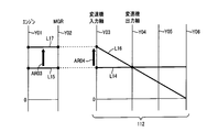
- FIG. 3 is a collinear diagram for explaining the downshift of the first planetary gear device 20 in the sequential shift.
- the vertical lines Y1, Y2, and Y3 in FIG. 3 indicate the relative rotational speeds of the first electric motor MG1, the engine 14, and the output gear 24 in order from the left side, and the distance between them is the gear ratio ⁇ 0 of the first planetary gear unit 20. It is determined according to. In FIG. 3, the higher the speed of rotation on the vertical lines Y 1, Y 2, Y 3, the higher the rotation speed.
- a solid line L01 indicates a relative rotational speed of the first electric motor MG1, the engine 14, and the output gear 24 before the downshift
- a solid line L02 indicates a relative rotation of the first electric motor MG1, the engine 14, and the output gear 24 after the downshift. Showing speed. While the vehicle is running, the rotational speed N OUT of the output gear 24 is constrained by the drive wheels 40, so it does not change unless the vehicle speed V changes, and does not change before and after the downshift as shown in FIG. Then, in the downshift elevated as the engine rotational speed Ne arrow AR01, therewith also the first electric motor speed N MG1 simultaneously rises as indicated by arrow AR02.
- the direction of change in the rotational speed between the first electric motor MG1 and the engine 14 is opposite to the arrows AR01 and AR02 in FIG. That is, the reverse is true for the downshift.
- the engine rotation speed Ne decreases, and at the same time, the first motor rotation speed NMG1 also decreases.
- the first electric motor rotational speed N MG1 varies with the engine rotational speed Ne regardless of whether the first planetary gear apparatus 20 is upshifted or downshifted, the first electric motor MG1 is the first planetary gear apparatus 20 that is a transmission mechanism. It is possible to positively change the engine rotational speed Ne during the shifting process.
- FIG. 4 is a diagram illustrating a signal input to the electronic control device 80 and a signal output from the electronic control device 80, and for explaining a main part of a control function provided in the electronic control device 80. It is a functional block diagram.
- the electronic control unit 80 includes a so-called microcomputer including a CPU, a ROM, a RAM, an input / output interface, and the like, and performs signal processing according to a program stored in the ROM in advance while using a temporary storage function of the RAM. By executing this, vehicle control such as hybrid drive control for the engine 14, the first electric motor MG1, and the second electric motor MG2 is executed.
- the electronic control unit 80 represents a signal from the engine speed sensor 50 representing the engine speed Ne, and an engine water temperature TEMP W from the engine water temperature sensor 51 provided in the cylinder block of the engine 14.
- a signal indicating presence / absence a signal indicating the accelerator opening Acc, which is an operation amount of the accelerator pedal 60 detected by the accelerator opening sensor 58, and an opening of an electronic throttle valve for adjusting an intake air amount into the cylinder of the engine 14
- first motor rotational speed N MG1 (hereinafter referred to as “first motor rotational speed N MG1 ”) of the first electric motor MG1 detected by the
- a signal representing the rotational speed N MG2 of the electric motor MG2 (hereinafter referred to as “second electric motor rotational speed N MG2 ”), a signal representing the charging or discharging current I CD of the power storage device 68, and the remaining charge (charging state) of the power storage device 68 )
- a signal indicating the SOC, a shift lever position signal corresponding to the operation position P SH from the lever operation position sensor 70 which is a position sensor for detecting the operation position (operation position) P SH of the shift lever 46, and the like are supplied. Is done.
- the electronic control unit 80 sends a control signal for controlling the engine output to the throttle actuator for operating the throttle valve opening ⁇ TH of the electronic throttle valve provided in the intake pipe of the engine 14, for example, an engine output control.
- the drive signal, the fuel supply amount signal for controlling the fuel supply amount to the intake pipe or the cylinder of the engine 14 by the fuel injection device, the ignition signal for instructing the ignition timing of the engine 14 by the ignition device, and the operation of each electric motor MG1, MG2 Command signals to be commanded are output.
- the throttle actuator is driven based on the accelerator opening Acc, and the throttle control of the engine 14 is executed so that the throttle valve opening ⁇ TH increases as the accelerator opening Acc increases. Is done. In this throttle control, the corresponding one-to-one relationship between the accelerator opening Acc and the throttle valve opening theta TH.
- the virtual shift stage is switched by the operation of the shift lever 46 by the driver, so that the response suitable for the will of the driver is obtained.
- the rotational speed of the first ring gear R1 is constrained by the vehicle speed V, which corresponds to the change in the speed ratio ⁇ 0.
- the engine speed Ne can be changed by the torque generated by one or both of the engine 14 itself and the first electric motor MG1, but when the engine speed Ne is finely controlled, while it is advantageous to control the engine rotational speed Ne by the torque T MG1 generated by the first electric motor MG1 (hereinafter referred to as the first electric motor torque T MG1 ), when the engine rotational speed Ne is changed greatly at an early stage, Control of the engine rotational speed Ne by torque Te generated by the engine 14 (hereinafter referred to as engine torque Te) is advantageous because a large torque can be obtained earlier.
- the electronic control unit 80 of this embodiment has a control function for quickly executing the sequential shift according to the will of the driver. Yes. The main part of the control function will be
- the electronic control unit 80 includes a shift mode determination unit 84 as a shift mode determination unit, a shift request determination unit 86 as a shift request determination unit, and an engine rotation as an engine rotation speed change amount calculation unit.
- the engine rotation speed control means 94 includes a shift delay detecting means 96 as a shift delay detecting unit.
- Shift mode determining means 84 is sequentially detects the operation position P SH of the shift lever 46 by a signal from the lever operation position sensor 70, shift mode wherein sequential shifting of the mode or first planetary gear unit 20 of the vehicle 6 It is determined whether or not the mode (sport mode). Specifically, if the shift lever 46 is in the “M” position, the sequential shift mode is established, and the shift mode is the sequential shift mode. As described above, the sequential shift, which is the shift of the first planetary gear device 20 in the sequential shift mode, is a virtual stepped change in which the gear ratio ⁇ 0 of the first planetary gear device 20 is changed stepwise during forward travel.
- the engine speed Ne also changes in accordance with the change in the speed ratio ⁇ 0, so that the engine speed Ne changes discretely, that is, stepwise according to the driver's operation, for example, the operation of the shift lever 46. This is also the speed change of the first planetary gear unit 20 to be caused.
- the shift request determining means 86 determines whether or not the driver has requested a shift of the vehicle 6, that is, a shift of the first planetary gear device 20 in the sequential shift mode. Whether or not the speed change mode of the vehicle 6 is the sequential speed change mode is based on the determination of the speed change mode determination means 84. For example, the shift request determination unit 86 sequentially detects the operation position P SH of the shift lever 46 based on a signal from the lever operation position sensor 70, and the shift lever 46 is operated to the “+” position or the “ ⁇ ” position. In this case, it is determined that the shift request has been made. Further, if the sequential shift is executed even when the increase amount of the accelerator opening Acc exceeds a predetermined value, the increase of the accelerator opening Acc is regarded as the shift request for downshift, for example. There is no problem.
- the engine speed change amount calculation means 88 when the shift request determination means 86 determines that the shift request is made, that is, when the shift request is made in the sequential shift mode, the sequential speed based on the shift request.
- a change amount Ne of the engine rotational speed Ne before and after the shift that is, a rotational speed change width Ne of the engine 14 which is a difference between the engine rotational speed Ne before the sequential shift and the engine rotational speed Ne (target value) after the sequential shift. Is calculated before the start of the sequential shift.
- the gear ratio ⁇ 0 achieved in each of the gears (1st to 4th) of the first planetary gear device 20 is set in advance, and the gear stage SH1 before the sequential gear shift (hereinafter referred to as the gear stage SH1 before the gear shift) and the sequential gear. Since the post-shift gear stage SH2 (hereinafter referred to as the post-shift gear stage SH2) is determined when the shift request is made, the pre-shift gear stage SH1, the post-shift gear stage SH2, the shift request, or the change amount Ned is calculated.
- the change amount Ned of the engine rotation speed Ne before and after the sequential shift (hereinafter referred to as a shift engine rotation speed change amount Ned) can be calculated. .
- the required torque calculation means 90 is a target value of the sequential shift time TIMEcg required from the start to the end of the sequential shift when the engine speed change amount Ned during shift is calculated by the engine rotation speed change amount calculation means 88.
- the target sequential shift time TIMEcgt is determined.
- the shift required torque Tnd that is, the engine rotation speed Ne required for changing the engine rotation speed Ne from the rotation speed before the shift to the target rotation speed after the shift is changed.
- the total torque Tnd of the engine 14 and the first electric motor MG1 for changing from the previous rotational speed to the target rotational speed after the shift is calculated and determined.
- the target sequential shift time TIMEcgt and the required shift torque Tnd are determined at least before the start of the change in the engine rotational speed Ne in the sequential shift.
- the start of sequential shift which is the start of sequential shift time TIMEcg
- the end of sequential shift which is the end of sequential shift time TIMEcg
- the target sequential shift time TIMEcgt is experimentally determined in advance so as to suppress, for example, the deterioration of responsiveness and the deterioration of comfort due to a shift shock, and the engine torque Te and vehicle speed before the start of sequential shift.
- the shift required torque Tnd is obtained by experimentally determining the inertia of the engine 14 and the engine synchronous rotating member rotating together with the engine 14, the rotational resistance of the engine 14 and the engine synchronous rotating member, and the like. In consideration of the above, it can be calculated based on the target sequential shift time TIMEcgt and the engine speed change amount Ned during shift. For example, the required shift speed Tnd increases as the target sequential shift time TIMEcgt is shorter, and increases as the shift engine rotational speed change amount Ned increases.
- the torque sharing ratio determining means 92 uses the predetermined relationships (maps) shown in FIGS.
- An engine-side torque sharing ratio RTTe (unit:%, for example), which is a torque sharing ratio RTTe of the engine 14 with respect to the shift required torque Tnd (total torque amount Tnd), and a torque sharing ratio RTTmg of the first electric motor MG1 with respect to the shift required torque Tnd.
- the motor side torque sharing ratio RTTmg (unit:%, for example) is determined.
- the engine-side torque sharing ratio RTTe and the motor-side torque sharing ratio RTTmg are determined at least before the start of the change in the engine rotation speed Ne in the sequential shift, but the shift delay detecting means in the middle of the change in the engine rotation speed Ne in the sequential shift It may be changed depending on 96 judgments.
- FIG. 5 is an engine-side torque sharing ratio calculation map determined experimentally in advance for determining the engine-side torque sharing ratio RTTe based on the engine speed change amount Ned during shifting.
- FIG. 6 shows an experiment in advance for determining the engine-side torque sharing ratio RTTe based on the battery discharge limit power Wout (unit: kW, for example), which is the upper limit value (discharge limit power) Wout of the power storage device 68.
- 3 is a map for calculating a predetermined engine side torque sharing ratio.
- FIG. 7 is an engine-side torque sharing ratio calculation map determined experimentally in advance for determining the engine-side torque sharing ratio RTTe based on the engine water temperature TEMP W indicating the temperature of the engine 14.
- FIGS. 5 to 7 are experimentally obtained and set in advance so as to ensure fine controllability and good responsiveness of the engine rotational speed Ne in the sequential shift.
- the engine-side torque sharing ratio RTTe increases as the engine speed change amount Ned during shifting increases. This is because when the target sequential shift time TIMEcgt is fixed, the inertia torque associated with the change in the engine rotational speed Ne increases as the engine rotational speed change amount Ned during the shift increases. This is because it is easier to generate a larger torque than the first electric motor MG1. For example, if the engine speed change amount Ned during shifting is Ned_01 in FIG. 5, the engine-side torque sharing ratio RTTe becomes RTTe_01 from the point PA.
- the engine-side torque sharing ratio RTTe increases as the battery discharge limit power Wout decreases, in other words, as the limit on the discharge power of the power storage device 68 increases.
- the horizontal axis in FIG. 6 is replaced with the battery discharge limit power Wout, and the battery charge limit power Win (unit: kW, for example) is the upper limit value (charge limit power) Win of the power storage device 68. ).
- the first motor torque T MG1 is limited by the battery discharge limit power Wout or the battery charge limit power Win depending on the direction of change of the engine rotation speed Ne in the sequential shift and the rotation direction of the first motor MG1 during the shift. It is because it is restricted. If the horizontal axis in FIG. 6 is replaced with the battery charge limit power Win, the engine-side torque sharing ratio RTTe increases as the battery charge limit power Win decreases, in other words, the limit on the charge power of the power storage device 68 increases.
- the battery discharge limit power Wout and the battery charge limit power Win are, for example, limit values that are changed according to the remaining charge SOC of the power storage device 68 or the temperature of the power storage device 68 in order to ensure the durability of the power storage device 68. It is.
- the engine-side torque sharing ratio RTTe obtained in FIG. 5 for example, RTTe_01 is the engine-side torque sharing ratio determined in FIG. It is the minimum value of RTTe.
- the engine-side torque sharing ratio RTTe increases as the temperature of the engine 14, that is, the engine water temperature TEMP W decreases, for example, before the warm-up of the engine 14 is completed. This is because the lower the engine coolant temperature TEMP W , the greater the rotational resistance of the engine 14 and the longer the sequential shift time TIMEcg.
- the engine-side torque sharing ratio RTTe obtained in FIG. 5, for example, RTTe_01 is the engine-side torque sharing ratio RTTe determined in FIG. Is the minimum value.
- the torque sharing ratio determining means 92 determines that the engine speed change amount Ned during shifting, the battery discharge limit power Wout, and the engine water temperature. Based on TEMP W , engine side torque sharing ratio RTTe is calculated and determined. 6 may be replaced with the battery charge limit power Win as described above, and the engine side torque sharing ratio RTTe may be calculated based on the battery charge limit power Win.
- the engine speed control means 94 when the shift request determination means 86 determines that the shift request has been made, that is, when the shift request is made in the sequential shift mode, the shift required torque Tnd and the engine-side torque share. based on the ratio RTTe and the electric motor side torque distribution ratio RTTmg, to determine the engine torque Te and the first electric motor torque T MG1 in the sequential shift. Then, the engine rotational speed Ne is changed from the rotational speed before the sequential shift to the target rotational speed after the sequential shift with the determined engine torque Te and first motor torque TMG1 .
- the engine rotational speed control means 94 is first necessary on the engine 14 side to change the engine rotational speed Ne from the rotational speed before the shift to the target rotational speed after the shift within the target sequential shift time TIMEcgt.
- the engine-side required torque T01e that is, the share T01e of the engine 14 in the required shift torque Tnd is calculated by multiplying the required shift speed Tnd by the engine-side torque sharing ratio RTTe.
- the motor-side required torque T01mg that is necessary on the first motor MG1 side to change the engine rotation speed Ne from the rotation speed before the shift to the target rotation speed after the shift, that is, the shift Of the necessary torque Tnd the share T01mg of the first motor MG1 is calculated by multiplying the required shift speed Tnd by the motor-side torque sharing ratio RTTmg.
- These shift required torque Tnd, engine side required torque T01e, and motor side required torque T01mg are all torques around the output shaft 15 for directly rotating the output shaft 15 of the engine 14, and
- the engine rotational speed Ne is increased during the downshift, so that the torque is in the direction of increasing the engine rotational speed Ne.
- the upshift of the first planetary gear unit 20 the engine rotational speed Ne is upshifted. The torque in the direction of decreasing the engine rotational speed Ne since the engine speed Ne is decreased.
- the engine speed control means 94 calculates a value obtained by adding the engine-side required torque T01e to the engine torque Te at the start of sequential shift as engine torque Te during sequential shift (hereinafter referred to as engine torque Tecg during shift). (See FIGS. 9 and 10).
- calculating a material obtained by adding the electric motor-side required torque T01mg to the first electric motor torque T MG1 during sequential shift start the first electric motor torque T MG1 in the sequential shift (hereinafter, referred to as a first motor torque T MG1CG during a shift) as (See FIGS. 9 and 10).
- the engine speed control means 94 takes into account the gear ratio ⁇ 0 of the first planetary gear device 20.
- the first electric motor torque TMG1 during the sequential shift is calculated.
- Engine speed control means 94 this manner is determined by calculating the first-motor torque T MG1CG during shifting the shift in engine torque Tecg, to the first electric motor MG1 causes output a shift in engine torque Tecg engine 14 During the speed change, the first electric motor torque TMG1CG is output, thereby changing the engine rotational speed Ne from the rotational speed before the shift to the target rotational speed after the shift. That is, the sequential shift is performed.
- the engine speed control means 94 sequentially detects the engine speed Ne, and when the engine speed Ne reaches a target speed after sequential shift (hereinafter referred to as a post-shift target engine speed).
- the target rotational speed after the sequential shift (the target engine rotational speed after the shift) is a downshift of the first planetary gear unit 20
- the engine rotational speed change amount Ned during the shift is added to the engine rotational speed Ne before the sequential shift.
- this is a value obtained by subtracting the engine rotational speed change amount Ned during shifting from the engine rotational speed Ne before the sequential shift.
- the shift delay detecting means 96 detects a delay in the change of the engine rotation speed Ne during the execution of the sequential shift, that is, during the change of the engine rotation speed Ne in the sequential shift, and the sequential shift is the target sequential shift time. Judge whether to end within TIMEcgt. In short, it is determined whether or not there is a shift delay of the sequential shift during the sequential shift. For this purpose, the shift delay detecting means 96 performs the target engine rotation after the shift within the target sequential shift time TIMEcgt based on the engine rotation speed Ne before the sequential shift, the post-shift target engine rotation speed, and the target sequential shift time TIMEcgt.
- the target engine rotational speed Net during shifting which is the target engine rotational speed during sequential shift, is sequentially determined and updated over time from the start to the end of sequential shift.
- the shift delay detecting unit 96 assumes that the engine rotational speed Ne changes linearly from the rotational speed before the sequential shift to the target engine rotational speed after the shift within the target sequential shift time TIMEcgt, and changes the target engine rotational speed Net during the shift. Set as a function of time. Further, the shift delay detecting means 96 sequentially detects the engine speed Ne from the start to the end of the sequential shift.
- the shift delay detecting means 96 when the engine rotational speed Ne is downshifted by the sequential shift, is reduced when the engine rotational speed Ne becomes lower than the target engine rotational speed Net during the shift by a difference equal to or greater than a predetermined shift delay determination value LDNe. It is determined that the change in Ne is delayed, and it is determined that the sequential shift does not end within the target sequential shift time TIMEcgt. Further, during the upshift of the sequential shift, when the engine speed Ne becomes higher than the target engine speed Net during the shift with a difference greater than a predetermined shift delay determination value LDNe, the change in the engine speed Ne is delayed. Therefore, it is determined that the sequential shift does not end within the target sequential shift time TIMEcgt.
- the shift delay detecting means 96 is configured to determine whether the actual engine torque Te or the first electric motor torque T MG1 is a command value (torque command) to the engine 14 or the first electric motor MG1 while the engine rotational speed Ne is changing in the sequential shift. Value) is sequentially determined.
- the engine torque Te and the first motor torque TMG1 are sequentially detected by a torque sensor or the like, but may be detected directly or indirectly by other methods.
- the shortage of the engine torque Te or the first electric motor torque TMG1 is a shortage of torque that causes the change in the engine rotational speed Ne to be delayed by the sequential shift, and more specifically, the engine 14 at the sequential shift.
- the torque is insufficient in the direction of rotation speed change. In other words, there is insufficient torque with the direction of change in the rotational speed of the engine 14 in the sequential shift as the positive direction.
- the torque sharing ratio determining unit 92 determines that the engine-side torque sharing ratio RTTe and the motor-side torque have been determined when the shift delay detecting unit 96 determines.
- the share ratio RTTmg is changed during the change of the engine speed Ne.
- the torque sharing ratio determining unit 92 is configured to determine a torque sharing ratio (engine-side torque of the engine 14 or the first motor MG1 having a large shortage of the engine torque Te or the first motor torque TMG1 with respect to the torque command value.
- the sharing ratio RTTe or the motor-side torque sharing ratio RTTmg) is lowered during the change of the engine rotation speed Ne from before the determination by the shift delay detecting means 96.
- the torque sharing ratio of the other engine 14 or the first electric motor MG1 is increased more than before the above determination by the shift delay detecting means 96.
- each torque sharing ratio RTTe, RTTmg there is no particular limitation on the pulling amount and pulling amount of each torque sharing ratio RTTe, RTTmg, for example, the one torque sharing ratio RTTe or RTTmg is made zero, and the other torque sharing ratio RTTe or RTTmg is Made 100%.
- the torque sharing ratio determining means 92 changes the engine side torque sharing ratio RTTe and the motor side torque sharing ratio RTTmg during the change of the engine speed Ne based on the determination of the shift delay detecting means 96
- the engine rotational speed control means 94 again to determine the engine torque Te and the first electric motor torque T MG1 during the sequential transmission on the basis of the changed engine side torque distribution ratio RTTe and the motor-side torque distribution ratio RTTmg, and the re-determined Sequential shifting is continued with the engine torque Te and the first electric motor torque TMG1 .
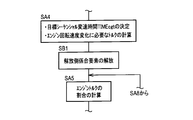
- FIG. 8 is a flowchart for explaining a main part of the control operation of the electronic control unit 80, that is, a control operation for executing the sequential shift, and is repeatedly executed with an extremely short cycle time of, for example, about several milliseconds to several tens of milliseconds. Is done.
- the control operation shown in FIG. 8 is executed alone or in parallel with other control operations.
- step it is determined whether or not the shift mode of the vehicle 6 is the sequential shift mode (sport mode). If the determination at SA1 is affirmative, that is, if the mode is the sequential shift mode, the process proceeds to SA2. On the other hand, if the determination of SA1 is negative, this flowchart ends.
- SA2 corresponding to the shift request determining means 86, it is determined whether or not the shift request has been made. If the determination at SA2 is affirmative, that is, if the shift request is made, the process proceeds to SA3. On the other hand, when the determination of SA2 is negative, this flowchart ends.
- the target sequential shift time TIMEcgt is determined.
- the torque required for the change in the engine speed Ne that is, the required shift speed Tnd is calculated based on the target sequential shift time TIMEcgt and the shift engine speed change amount Ned calculated in SA3.
- the process proceeds to SA5.
- the ratio of the engine torque Te to the shift required torque Tnd calculated in SA4 that is, the engine side torque sharing ratio RTTe is calculated and determined.
- the motor side torque sharing ratio RTTmg is calculated and determined. If the determination of SA8 described later is affirmed and SA5 is executed again during execution of the sequential shift, the torque sharing of the engine 14 or the first electric motor MG1 having a large shortage of torque Te, TMG1 is large.
- the ratio engine-side torque sharing ratio RTTe or motor-side torque sharing ratio RTTmg
- SA6 the process proceeds to SA6.
- SA7 corresponding to the engine rotational speed control means 94, is output engine torque Te and the first electric motor torque T MG1 determined at SA6. After SA7, the process proceeds to SA8.
- SA8 corresponding to the shift delay detecting means 96, it is determined whether or not the actual engine torque Te or the first motor torque TMG1 is insufficient and the shift delay of the first planetary gear unit 20 has occurred. The When it is determined that the sequential shift does not end within the target sequential shift time TIMEcgt, it is determined that the shift delay has occurred. If the determination at SA8 is affirmative, that is, if the actual engine torque Te or first motor torque TMG1 is insufficient and the shift delay occurs, the process proceeds to SA5. On the other hand, if the determination at SA8 is negative, the operation proceeds to SA9.
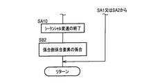
- SA9 corresponding to the engine speed control means 94, it is determined whether or not the engine speed Ne has reached the post-shift target engine speed. If the determination at SA9 is affirmative, that is, if the engine speed Ne has reached the post-shift target engine speed, the process proceeds to SA10. On the other hand, if the determination at SA9 is negative, the operation goes to SA7.
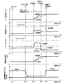
- FIG. 9 shows, as an example, the case where the downshift (sequential downshift) of the sequential shift is performed during inertial traveling with the accelerator pedal 60 released, that is, during coasting, and the engine 14 and the first electric motor MG1 in the sequential shift. It is a time chart for demonstrating torque control of.
- the time chart of the prior art is shown by a broken line together with the time chart of the present embodiment shown by a solid line.
- the engine torque Te is not used for changing the engine rotational speed Ne in the sequential shift, but the engine speed Ne is changed exclusively by the first electric motor torque T MG1 and the sequential shift proceeds. .
- This prior art is the same in the time chart of FIG. 10 described later.
- two-dot chain line L03 shows a first electric motor torque T MG1 when the engine-side torque distribution ratio RTTe is 0%
- the two-dot chain line L04 is the engine side torque distribution ratio RTTe 100%
- the broken line L05 indicates the engine torque Te when the engine side torque sharing ratio RTTe is 0%.
- the accelerator opening Acc is, for example, zero from beginning to end. Since the second motor rotation speed NMG2 is constant from beginning to end, the vehicle speed V is constant in the time chart of FIG. Since the engine torque Te is a negative value before the time point tA3 and after the time point tA4 in the time chart (solid line) of the engine torque Te, the engine 14 functions as a traveling load and generates a so-called engine brake.
- the vehicle 6 is in a traveling state in the sequential shift mode (sport mode). Accordingly, the determination of SA1 in FIG. 8 is affirmed at time tA1.
- the shift lever 46 is operated to the “ ⁇ ” position (see FIG. 2), for example, and the shift request, specifically, the downshift for causing the first planetary gear device 20 to downshift. Since the request has been made, the determination of SA2 in FIG. 8 is affirmed.
- the sequential shift specifically the sequential down shift, is started, and at the time tA4, the sequential shift is completed in this embodiment.
- the sequential shift starts from the time tA3 as in the present embodiment, but the sequential shift ends at the time tA5 after the time tA4.
- the engine speed Ne reaches the post-shift target engine speed as time elapses.
- the first motor rotation speed N MG1 is also increasing.
- the sequential shift time TIMEcg that is the time from the time tA3 to the time tA4 is the target sequential shift time TIMEcgt. It matches.
- the engine torque Te is not changed in order to increase the engine speed Ne during the sequential shift (from time tA3 to time tA5).
- the motor torque T MG1 is increased with respect to that before the start of the shift, and the engine rotation speed Ne is increased exclusively by the increase in the first motor torque T MG1 during the sequential shift.
- the in sequential shift (tA3 time ⁇ tA4 point), increases the engine torque Te and the first electric motor torque T MG1 together to the front shift start As a result, the engine speed Ne is increased.
- the engine side torque sharing ratio RTTe is determined to be 80%, for example, and the motor side torque sharing ratio RTTmg is determined to be 20%, for example.
- the engine-side torque sharing ratio RTTe is appropriately determined, and the engine rotational speed Ne is changed using the engine torque Te during the sequential shift. Therefore, the sequential shift time is compared with the prior art. TIMEcg can be made shorter. Therefore, the shift response of the sequential shift can be improved and drivability can be improved.
- FIG. 10 shows an example in which the upshift (sequential upshift) of the sequential shift is performed during the acceleration operation in which the accelerator pedal 60 is depressed and the accelerator is on, and the engine 14 and the first electric motor in the sequential shift are illustrated.
- 3 is a time chart for explaining torque control of MG1.
- the time chart of the prior art is shown by a broken line together with the time chart of the present embodiment shown by a solid line, as in FIG.
- two-dot chain line L06 shows a first electric motor torque T MG1 when the engine-side torque distribution ratio RTTe is 0%
- the two-dot chain line L07 is the engine side torque distribution ratio RTTe 100%
- the broken line L08 indicates the engine torque Te when the engine side torque sharing ratio RTTe is 0%. Since the second motor rotation speed NMG2 is constant from beginning to end, the vehicle speed V is constant in the time chart of FIG.
- the vehicle 6 is in a traveling state in the sequential shift mode (sport mode). Therefore, the determination of SA1 in FIG. 8 is affirmed at time tB1.
- the accelerator pedal 60 is depressed and the accelerator is on. That is, the acceleration operation by the driver is performed at time tB2.
- the shift request specifically, an upshift that causes the first planetary gear device 20 to upshift. Since the request has been made, the determination of SA2 in FIG. 8 is affirmed.
- the sequential shift specifically the sequential up shift, is started, and at the time tB5, the sequential shift is completed in this embodiment.
- the sequential shift starts from the time tB4 as in the present embodiment, but the sequential shift ends at the time tB6 after the time tB5.
- the engine speed Ne reaches the post-shift target engine speed as time elapses.
- the first motor rotation speed N MG1 is also decreased in synchronization therewith.
- the sequential shift time TIMEcg that is the time from the time tB4 to the time tB5 is the target sequential shift time TIMEcgt. It matches.
- the engine side torque sharing ratio RTTe is determined to be 80%, for example, and the motor side torque sharing ratio RTTmg is determined to be 20%, for example.
- the sequential shift time TIMEcg can be further shortened in the sequential up shift illustrated in FIG. 10 as compared with the prior art. . Therefore, the shift response of the sequential shift can be improved and drivability can be improved.
- FIG. 11 shows an example in which the downshift (sequential downshift) of the sequential shift is performed during inertial traveling with the accelerator pedal 60 released, that is, during coasting, and a shift delay is detected during the sequential shift.
- 6 is a time chart for explaining torque control of the engine 14 and the first electric motor MG1 in the case.
- FIG. 11 shows that the first electric motor torque T MG1 is larger in variation with respect to the torque command value than the engine torque Te in the above-described sequential shift, and the torque for changing the engine rotational speed Ne is the first electric motor torque T MG1 .
- An example in which torque becomes insufficient due to variation is shown.
- two-dot chain line L09 shows a first electric motor torque T MG1 when the engine-side torque distribution ratio RTTe is 0%
- the two-dot chain line L10 is the engine side torque distribution ratio RTTe 100%
- the engine torque Te is shown.
- the accelerator opening Acc is, for example, zero at all times.
- the second motor rotation speed NMG2 is constant from beginning to end
- the vehicle speed V is constant in the time chart of FIG.
- the engine torque Te is a negative value before the time point tC3 and after the time point tC5 in the time chart (solid line) of the engine torque Te
- the engine 14 functions as a traveling load and generates a so-called engine brake.
- the vehicle 6 is in a traveling state in the sequential shift mode (sport mode). Accordingly, the determination of SA1 in FIG. 8 is affirmed at time tC1.
- the shift lever 46 is operated to the “ ⁇ ” position (see FIG. 2), for example, so that the shift request, specifically, the downshift of the first planetary gear device 20 is performed. Since the request has been made, the determination of SA2 in FIG. 8 is affirmed.
- the sequential shift specifically the sequential down shift, is started, and at the time tC5, the sequential shift is completed.
- an alternate long and short dash line L11 indicates the target engine speed Net during the shift from the start to the end of the sequential shift. As shown in FIG.
- the engine rotational speed Ne changes to be lower than the target engine rotational speed Net during shifting, and the engine rotational speed Ne and the target engine rotational speed during shifting.
- the difference from the speed Net increases with time.
- the engine rotational speed Ne is low with a difference equal to or greater than the shift delay determination value LDNe with respect to the target engine rotational speed Net during shifting.
- the first electric motor torque TMG1 is insufficient due to the variation. Therefore, at time tC4, it is determined that a shift delay of the first planetary gear device 20 has occurred in SA8 of FIG. 8, and the determination of SA8 is affirmed.
- the motor-side torque sharing ratio RTTmg and the engine-side torque sharing ratio RTTe are reset at SA5 in FIG. 8, and the motor-side torque sharing ratio RTTmg is lower than before tC4.
- the engine-side torque sharing ratio RTTe has been increased from before tC4.
- the motor-side torque sharing ratio RTTmg was 20% and the engine-side torque sharing ratio RTTe was 80% from the time tC3 to the time tC4, but from the time tC4 to the time tC5, the motor-side torque sharing ratio RTTmg was The engine-side torque sharing ratio RTTe is 100%. Accordingly, as shown in FIG.
- the target does not end the sequential shift is still a moderately elevated tC5 time as shown in the engine rotational speed Ne is dashed L12 if there is no change of the first electric motor torque T MG1 and the engine torque Te in such tC4 time when the in sequential shift time TIMEcgt would not be completed, by a change of the first electric motor torque T MG1 and the engine torque Te in the above tC4 time, larger than the engine increasing speed of rotational speed Ne is dashed L12 from tC4 time
- the engine speed Ne from the time point tC4 to the time point tC5 changes as indicated by the solid line L13. Therefore, the sequential shift started from the time point tC3 ends within the target sequential shift time TIMEcgt.
- the engine rotation speed control means 94 changes the engine rotation speed Ne by the torques Te and TMG1 generated by sharing at least one of the engine 14 and the first electric motor MG1 in the sequential shift.
- the engine 14 and the first electric motor for changing the engine rotation speed Ne as the shift engine rotation speed change amount Ned that is the rotation speed change width of the engine 14 is larger.
- the torque sharing ratio (engine-side torque sharing ratio RTTe) of the engine 14 with respect to the total torque amount Tnd of MG1 is large. Therefore, as the engine-side torque sharing ratio RTTe increases, the engine speed Ne can be changed with a greater torque by actively using the engine 14, and therefore the sequential shift time TIMEcg can be changed. It is possible to suppress an increase in the engine speed change amount Ned at the time of the shift, and to sufficiently ensure the responsiveness of the vehicle 6 to the driver's operation. That is, drivability at the sequential shift can be improved.
- the engine-side torque sharing ratio RTTe increases as the limit on the charging power or discharging power of the power storage device 68 increases. Therefore, even if there is a possibility that the first electric motor torque T MG1 is insufficient to rapidly change the engine rotational speed Ne by the sequential shift due to the restriction on the charging power or discharging power of the power storage device 68, the engine The change rate of the engine rotational speed Ne can be sufficiently obtained by the torque Te. Therefore, it is possible to suppress the sequential shift time TIMEcg from becoming long.
- the engine-side torque sharing ratio RTTe is larger as the engine water temperature TEMP W indicating the temperature of the engine 14 is lower. Therefore, even if it is difficult to change the engine speed Ne quickly due to the sequential shift due to the high rotational resistance (friction) of the engine 14 due to the low temperature of the engine 14, the engine torque Since the change speed of the engine rotation speed Ne can be sufficiently obtained by Te, it is possible to suppress the sequential shift time TIMEcg from becoming longer. For example, when the engine 14 is not sufficiently warmed up and the engine 14 is at a low temperature, the rotational resistance of the engine 14 increases. Therefore, according to FIG. 7, the engine-side torque sharing ratio RTTe, which is the vertical axis of FIG. 7, is larger when the engine 14 is before the warm-up is completed than after the warm-up is completed.
- the sequential shift is set in advance. If it is determined that it does not end within the shift time TIMEcgt, the determination is made while the torque sharing ratio RTTe or RTTmg of the engine 14 or the first electric motor MG1 having the larger torque shortage is changing the engine speed Ne. Lower than before. Therefore, compared to the case where it is not determined whether or not the sequential shift ends within the target sequential shift time TIMEcgt, the sequential shift can be completed more reliably within the target sequential shift time TIMEcgt, and drivability Can be improved.
- the sequential shift in which the engine side torque sharing ratio RTTe is determined according to the engine speed change amount Ned at the time of the shift as illustrated in FIG. Is a sequential downshift that increases the speed of the vehicle 6 before the start of the shift, and is performed while the vehicle 6 is coasting, or, as illustrated in FIG. 10, the engine speed Ne is decreased before the start of the shift.
- This is a sequential upshift and is performed during the acceleration operation of the vehicle 6. Accordingly, the responsiveness can be enhanced in the sequential shift in which the driver particularly desires the responsiveness of the vehicle 6, and the drivability in the sequential shift can be effectively improved.
- the engine-side torque sharing ratio RTTe in the sequential shift is determined based on the traveling condition of the vehicle 6 from a predetermined relationship.
- the traveling conditions are part or all of the engine rotational speed change amount Ned during shift in the sequential shift, the battery discharge limit power Wout, the battery charge limit power Win, the temperature of the engine 14, and the like. Therefore, the engine side torque sharing ratio RTTe can be easily and appropriately determined before the start of the sequential shift.
- FIG. 12 is a schematic configuration diagram for explaining a vehicle drive device 108 included in a hybrid vehicle 106 (hereinafter referred to as a vehicle 106) to which the present invention is applied, and electronic control for controlling the vehicle drive device 108.
- 3 is a functional block diagram for explaining a main part of a control function provided in the device 140.
- the vehicle drive device 8 corresponds to the engine 14, the travel drive motor MGR (corresponding to the motor of the present invention), the stepped automatic transmission 112, and the differential gear device 36 of the first embodiment.
- a differential gear device 114, an inverter 72, and a power storage device 68 electrically connected to the traveling drive motor MGR via the inverter 72 are provided.
- the engine 14, the travel drive motor MGR, the automatic transmission 112, the differential gear device 114, and the drive wheels 40 are connected in series.
- the vehicle drive device 108 is, for example, vertically disposed in front of a rear wheel drive, ie, FR (front engine / rear drive) type vehicle 106, and is preferably used for driving the drive wheels 40.
- the power of the engine 14 is transmitted from the transmission input shaft 116 of the automatic transmission 112 to the pair of drive wheels 40 through the automatic transmission 112, the differential gear device 114, the pair of axles 38, and the like sequentially. Is transmitted to.
- the power of the travel drive motor MGR is also transmitted from the transmission input shaft 116 to the pair of drive wheels 40 via the automatic transmission 112, the differential gear unit 114, the pair of axles 38, and the like in order.
- the travel drive motor MGR is the same motor generator as the first motor MG1 or the second motor MG2 of the first embodiment. Accordingly, the travel drive motor MGR can drive the drive wheels 40 and can apply a braking force to the drive wheels 40 by generating electric power while the vehicle is traveling, for example. Further, since the travel drive motor MGR is also connected to the output shaft 15 of the engine 14, it is possible to positively change the engine rotational speed Ne in the shifting process of the automatic transmission 112, for example.
- the electric motor that generates torque for changing the engine rotational speed Ne at the time of the sequential shift is the first electric motor MG1 in the first embodiment, but is the traveling drive electric motor MGR in the present embodiment.
- the automatic transmission 112 corresponds to the first planetary gear device 20 of the first embodiment, and is a speed change mechanism that constitutes a part of a power transmission path between the engine 14 and the drive wheels 40.
- the automatic transmission 112 is a stepped transmission that includes a plurality of planetary gear units and a plurality of engagement elements 118a, 118b, 118c, and 118d (referred to as engagement elements 118 unless otherwise specified). It is.
- the engagement element 118 is a wet multi-plate clutch or brake that engages or disengages hydraulically. Then, in the automatic transmission 112, clutch-to-clutch shift is performed by gripping the engagement element 118.
- the shift is performed by the engagement operation of the engagement side engagement element and the release operation of the release side engagement element.
- the engagement-side engagement element is an engagement element that is released before the shift of the automatic transmission 112 and is engaged after the shift.
- the release-side engagement element is an engagement element that is engaged before the automatic transmission 112 is shifted and released after the shift.
- the engagement-side engagement element and the release-side engagement element are different engagement elements, but each is one of the plurality of engagement elements 118.
- the automatic transmission 112 is, for example, a four-speed transmission, and the automatic transmission 112 has a first gear (1st), a second gear ( 2nd), a third gear (3rd), and a fourth gear (4th).
- the gear ratio gamma AT and the third difference between the speed ratio gamma AT corresponding to the gear ratio gamma AT and the second-speed gear stage corresponding to the first shift stage is corresponding to the second gear shift stage greater than the difference between the speed ratio gamma AT corresponding to the speed shift stage
- the difference between the speed ratio gamma AT corresponding gear ratio gamma AT corresponding to the second shift stage and its third-speed shift stage is the first third speed greater than the difference between the speed ratio gamma AT corresponding to the gear ratio gamma AT and the fourth speed gear stage corresponding to the shift stage.
- the shift speed before and after the shift is lower, that is, the shift speed before and after the shift is lower, respectively, before and after the shift.
- the amount of change in the gear ratio ⁇ AT increases.
- the automatic transmission 112 is automatically shifted based on the vehicle speed V and the accelerator opening Acc when the shift position P SH of the shift lever 46 in FIG. 2 is the forward automatic shift travel position “D”. Further, when the shift position P SH is the forward manual shift travel position “M”, the automatic transmission 112 performs an upshift one step each time the shift lever 46 is operated to the “+” position. On the other hand, every time the shift lever 46 is operated to the “ ⁇ ” position, a downshift is performed by one step.
- the shift of the automatic transmission 112 when the shift position PSH is the forward manual shift travel position “M” corresponds to the sequential shift described in the first embodiment.
- FIG. 13 is a collinear diagram for explaining the downshift of the automatic transmission 112.
- Vertical lines Y01, Y02, Y03, and Y04 in FIG. 13 indicate the relative rotational speeds of the engine 14, the travel drive motor MGR, the transmission input shaft 116, and the transmission output shaft 120 in order from the left side.
- the vertical lines Y05 and Y06 indicate the relative rotational speeds of the rotating elements included in the automatic transmission 112 other than the transmission input shaft 116 and the transmission output shaft 120. In FIG. 13, the higher the vertical line Y01 to Y06, the higher the rotation speed.
- Solid lines L14 and L15 indicate the relative rotational speeds of the rotating elements such as the engine 14, the travel drive motor MGR, the transmission input shaft 116, the transmission output shaft 120, etc.
- the solid lines L16 and L17 indicate the downshift.
- the relative rotational speed of each of the rotating elements after the shift is shown. Since the rotational speed of the transmission output shaft 120 is constrained by the drive wheels 40 during traveling of the vehicle, it does not change unless the vehicle speed V changes, and does not change before and after the downshift as shown in FIG.
- the engine rotational speed Ne and the rotational speed N MGR of the travel drive motor MGR (hereinafter referred to as the motor rotational speed N MGR ) increase as indicated by the arrow AR03 and at the same time as indicated by the arrow AR04.
- the rotational speed of the transmission input shaft 116 also increases. As shown in FIG. 12, since the engine 14, the travel drive motor MGR, and the transmission input shaft 116 are directly connected in series, the engine rotation speed Ne, the motor rotation speed NMGR, and the rotation of the transmission input shaft 116 The speed is the same as each other.
- the direction of change in the rotational speed of the engine 14, the travel drive motor MGR, and the transmission input shaft 116 is opposite to the arrows AR03 and AR04 in FIG. That is, the reverse is true for the downshift.
- the engine rotation speed Ne decreases and the motor rotation speed N MGR also decreases.
- the electronic control device 140 of the present embodiment is similar to the electronic control device 80 of the first embodiment in that the shift mode determining means 84, the shift request determining means 86, the engine speed change amount calculating means 88, and the required torque. Calculation means 90 and torque sharing ratio determination means 92 are provided.
- the electronic control unit 140 includes an engine rotation speed control unit 142 instead of the engine rotation speed control unit 94 included in the electronic control unit 80.
- the engine rotation speed control unit 142 includes a shift delay detection unit 96 as with the engine rotation speed control unit 94 of the first embodiment. The control functions described in FIG.
- Example 12 are basically the same if the first planetary gear unit 20 of the first embodiment is replaced with the automatic transmission 112 and the first electric motor MG1 of the first embodiment is replaced with the travel drive motor MGR. . Therefore, the difference from Example 1 after such replacement will be described below.
- the engine rotation speed control means 142 has a function as an engagement element control means for controlling the engagement operation or the release operation of the engagement element 118, and the shift request determination means 86 determines that the shift request has been made.
- the hydraulic pressure supplied to the disengagement engagement element before the start of the change of the engine rotational speed Ne that is, before the start of the sequential shift.
- the release side engagement element is released by lowering the release pressure.
- the sequential shift is started. That is, the engine rotation speed Ne starts to change at the sequential shift.
- the engine rotation speed control means 142 maintains the disengagement-side engagement element and the engagement-side engagement element in the released state during the change of the engine rotation speed Ne in the sequential shift, that is, during the sequential shift. .
- the engine rotational speed control means 142 is configured so that after the engine rotational speed Ne reaches the post-shift target engine rotational speed, that is, after the sequential shift is completed, the engagement-side engagement element
- the engagement side engagement element is engaged by raising the engagement pressure, which is the supply hydraulic pressure to the valve.
- the engagement-side engagement element may be engaged at the same time when the engine rotation speed Ne reaches the post-shift target engine rotation speed.
- the engine rotation speed control unit 142 is different from the engine rotation speed control unit 94 in this respect, but is the same as the engine rotation speed control unit 94 in other points.
- FIGS. 14 and 15 are flowcharts of the first embodiment in the flowchart for explaining the main part of the control operation of the electronic control device 140, that is, the flowchart for explaining the control operation for executing the sequential shift.
- FIG. 9 is an excerpt showing steps different from FIG.
- SB1 is added between SA4 and SA5 in FIG. 8 as shown in FIG. 14, and SA10 in FIG. 8 is shown in FIG. SB2 is added between “Return”.
- SA6, SA7, SA9 and SA10 in FIG. 8 correspond to the engine rotation speed control means 142. .
- the process proceeds to SB1 in FIG. 14 after SA4 in FIG.
- the disengagement side engagement element is released.
- the engagement side engagement element is still in the released state, but in order to increase the responsiveness during the engagement operation of the engagement side engagement element, the engagement side engagement element It may be in a low-pressure standby state where the engagement pressure is such that the released state can be maintained while filling the mechanical play. If the engagement-side engagement element is in the low-pressure standby state, the low-pressure standby state of the engagement-side engagement element is continued until SB2 in FIG. 15 is executed. After SB1, the process proceeds to SA5 in FIG.
- SB1 and SB2 correspond to the engine speed control means 142.
- FIG. 16 shows, as an example, a case where the automatic transmission 112 performs a downshift (sequential downshift) during the coasting, that is, during coasting, of the engine 14 and the travel drive motor MGR in the sequential shift. It is a time chart for demonstrating torque control.
- the time chart of the prior art is shown by a broken line together with the time chart of the present embodiment shown by a solid line.
- the prior art in FIG. 16 is the same as the prior art in FIG. 9 of the first embodiment, that is, in the prior art, the engine torque Te is not used to change the engine rotational speed Ne in the sequential shift.
- the engine speed Ne is exclusively changed by a torque T MGR generated by the traveling drive motor MGR (hereinafter referred to as the motor torque T MGR ), and the sequential shift proceeds.
- two-dot chain line L18 indicates the motor torque T MGR when the engine-side torque distribution ratio RTTe is 0%
- the two-dot chain line L19 is the engine side torque distribution ratio RTTe is 100%
- the broken line L20 indicates the engine torque Te when the engine-side torque sharing ratio RTTe is 0%.
- the accelerator opening Acc is, for example, zero at all times.
- the vehicle speed V is constant from beginning to end.
- the engine 14 Since the engine torque Te is a negative value before the time point tD3 and after the time point tD4 in the time chart (solid line) of the engine torque Te, the engine 14 functions as a running load and generates the engine brake.
- the vehicle 106 is in a traveling state in the sequential shift mode (sport mode). Accordingly, the determination of SA1 in FIG. 8 is affirmed at time tD1.
- the shift lever 46 is operated to the “ ⁇ ” position (see FIG. 2), so that the shift request, specifically, the downshift request for downshifting the automatic transmission 112 is made. Since the determination is made, the determination of SA2 in FIG. 8 is affirmed.
- the release pressure is reduced, and the release side engagement element is released. Further, immediately after the time point tD2, the engagement pressure is slightly increased to a low pressure standby pressure that places the engagement side engagement element in the low pressure standby state, so that the engagement side engagement element is in the low pressure standby state. It is in a state.
- the sequential shift specifically the sequential down shift
- the sequential shift is completed in this embodiment.
- the sequential shift starts from the time tD3 as in the present embodiment, but the sequential shift ends at the time tD5 after the time tD4.
- the engine speed Ne reaches the post-shift target engine speed as time elapses.
- the motor rotational speed NMGR also increases.
- the sequential shift time TIMEcg that is the time from the time tD3 to the time tD4 is the target sequential shift time TIMEcgt. It matches.
- the engagement pressure is increased at time tD5, whereby the engagement-side engagement element is completely engaged at time tD5, but the engagement-side engagement element is completely engaged.
- time tD4 when the engine speed Ne reaches the target engine speed after shifting.
- the engine torque Te is not changed in order to increase the engine rotational speed Ne during the sequential shift (from time tD3 to time tD5).
- T MGR is increased with respect to that before the start of the shift, and the engine speed Ne is increased exclusively by increasing the motor torque T MGR during the sequential shift.
- both the engine torque Te and the motor torque T MGR are increased with respect to before the shift start.
- the engine rotation speed Ne is increased.
- the engine side torque sharing ratio RTTe is determined to be 80%, for example, and the motor side torque sharing ratio RTTmg is determined to be 20%, for example.
- the first planetary gear device 20 is replaced with the automatic transmission 112 with respect to the first embodiment.
- the sequential shift time TIMEcg as compared with the prior art. Can be made shorter.
- the sequential shift that discretely changes the engine rotational speed Ne in accordance with the driver's operation is performed by operating the shift lever 46. It may be a paddle shift performed by operating a paddle switch provided in the vicinity of the steering device, or a manual shift or the like.
- SA1 of FIG. 8 it is determined whether or not the sequential shift mode is in effect, for example, based on whether or not the shift position PSH is the forward manual shift travel position “M”.
- a shift mode in which the driver obtains responsiveness to the vehicles 6, 106 for example, a power mode that is selected by the driver when driving performance is more important than fuel efficiency, and a paddle that performs stepwise shifting by operating the paddle switch. If the shift mode or the manual mode, or the mode established by the operation of the paddle switch at the D position is selected, the determination of SA1 in FIG. 8 may be affirmed.
- the horizontal axis of FIG. 6 represents the battery discharge limit power Wout.
- the remaining charge SOC of the power storage device 68 or the temperature of the power storage device 68 is shown. May be used for the horizontal axis of FIG. This is because the battery discharge limit power Wout is reduced when the remaining charge SOC of the power storage device 68 is small, and is decreased when the temperature of the power storage device 68 is low.
- the horizontal axis of FIG. 7 is the engine water temperature TEMP W , but there is no particular limitation as long as it is a parameter representing the rotational resistance of the engine 14, and for example, the engine water temperature TEMP W is changed. Further, it may be the temperature of the engine oil that lubricates the inside of the engine 14, or may be the elapsed time from the start of the warm-up operation of the engine 14.
- FIGS. 5 to 7 are used to calculate the engine-side torque sharing ratio RTTe, but FIGS. 6 and 7 are not used, and FIG. RTTe can be calculated.
- the engine-side torque sharing ratio RTTe in FIGS. 5 to 7 is continuous with respect to each of the engine speed change amount Ned during shifting, the battery discharge limit power Wout, and the engine water temperature TEMP W. However, it may be changed in two steps or three or more steps.
- the sequential shift is a stepped shift with a total of four steps, but may be a stepped shift with two steps, three steps, or five steps or more.
- the automatic transmission 112 is a four-speed stepped transmission.
- the automatic transmission 112 may be a two-speed, three-speed, or a five-speed or higher stepped transmission. .
- the engine 14 and the travel drive motor MGR are directly connected to each other.
- a power transmission cutoff device capable of interrupting power transmission such as a clutch, is provided between the engine 14 and the travel drive motor MGR. It may be inserted between the two.
- the engine-side torque sharing ratio RTTe is continuously determined in advance using the engine speed change amount Ned during shifting as a parameter.
- the gear positions before and after the shift may be determined in advance as parameters. That is, the engine-side torque sharing ratio RTTe may be determined based on the gear positions before and after the sequential shift from the predetermined relationship.
- FIG. 17 is a schematic diagram for explaining an example in which the engine-side torque sharing ratio RTTe is determined in advance using the shift speeds before and after the sequential shift as parameters.
- the engine side torque sharing ratio RTTe is EG12 in the shift (upshift and downshift) between the first speed gear stage and the second speed gear stage of the first planetary gear device 20 (automatic transmission 112).
- the motor-side torque sharing ratio RTTmg is MG12
- the engine-side torque sharing ratio RTTe in the shift between the second gear and the third gear is EG23
- the motor-side torque sharing ratio RTTmg is The engine-side torque sharing ratio RTTe in the shift between the third speed shift stage and the fourth speed shift stage is EG34
- the motor side torque sharing ratio RTTmg is MG34.
- the engine-side torque sharing ratio RTTe is set to increase stepwise as the shift speed before the sequential shift and after the sequential shift are on the lower vehicle speed side.
- EG12 in FIG. 17 is larger than EG23
- EG23 is larger than EG34.
- 17 is smaller than MG23
- MG23 is smaller than MG34.
- the motor is not connected between the transmission output shaft 120 and the differential gear device 114 in FIG. 12.
- the friction clutch is a differential gear with the transmission output shaft 120.
- An electric motor (motor generator), which is interposed between the apparatus 114 and separate from the traveling drive motor MGR, is connected between the friction clutch and the differential gear unit 114. It can be done.
- the automatic transmission 112 is a stepped transmission, but may be a continuously variable transmission such as a belt type CVT. If the automatic transmission 112 is a continuously variable transmission, its gear ratio ⁇ AT is changed stepwise in the sequential shift.
- the first carrier CA1 is connected to the engine 14, the first sun gear S1 is connected to the first electric motor MG1, and the first ring gear R1 is connected to the output gear 24.
- the connection relationship is not necessarily limited thereto, and the engine 14, the first electric motor MG1, and the output gear 24 are each composed of the three rotating elements CA1, S1, and R1 of the first planetary gear device 20. It can be connected to any of the above.
- the ring gear R2 of the second planetary gear unit 22 is integrally connected to the ring gear R1 of the first planetary gear unit 20, but the connection destination of the ring gear R2 is the ring gear R1.
- the first planetary gear device 20 may be connected to the first carrier CA1.
- the ring gear R2 may be connected to somewhere in the power transmission path between the first planetary gear device 20 and the drive wheel 40 instead of the ring gear R1.
- the vehicle power transmission device 10 includes the second planetary gear device 22 in a part of the power transmission path between the second electric motor MG2 and the drive wheel 40.
- the second electric motor MG2 may be directly connected to the output gear 24 without the gear device 22.
- the gear ratio of the second planetary gear unit 22 is fixed.
- the second planetary gear unit 22 can change the gear ratio of the second planetary gear unit 22 such as an automatic transmission. It can be a machine.
- a transmission is not provided in the power transmission path between the output gear 24 and the drive wheel 40.
- a manual transmission that mechanically changes the gear ratio in the power transmission path.
- a mechanical transmission such as an automatic transmission may be provided.
- the input shaft 18 is connected to the engine 14 via the damper 16. However, the input shaft 18 is not directly connected to the engine 14 via the transmission belt or gears. It does not matter even if it is connected to.
- a power interrupting device such as a clutch is not provided between the engine 14 and the first planetary gear device 20, but such a power interrupting device is connected to the engine 14. It may be interposed between the first planetary gear device 20.
- the power interrupting device is provided between the first electric motor MG1 and the first planetary gear device 20 or the second electric motor MG2 and the second planetary gear device 22. It may be inserted between the two.
- the first planetary gear device 20 and the second planetary gear device 22 are both single planetary, but one or both of them may be double planetary.
- the engine 14 is connected to the first carrier CA1 constituting the first planetary gear unit 20 so that power can be transmitted, and the first motor MG1 is connected to the first sun gear S1 so that power can be transmitted.
- the first ring gear R1 is connected to the power transmission path to the drive wheel 40.
- the first planetary gear device 20 is replaced with two planetary gear devices, and the two planetary gear devices are The engine, electric motor, and driving wheel are connected to the rotating element of the planetary gear device so that power can be transmitted to the rotating element of the planetary gear device. It may be configured to be able to switch between a stepped transmission and a continuously variable transmission by controlling a connected clutch or brake.
- the second electric motor MG2 of the first embodiment is connected to the output gear 24 constituting a part of the power transmission path from the engine 14 to the driving wheel 40 via the second planetary gear unit 22,
- the electric motor MG2 can also be connected to the first planetary gear device 20 via an engagement element such as a clutch.
- the power transmission device 10 may be configured such that the differential state of the first planetary gear device 20 can be controlled by the electric motor MG2.
Landscapes
- Engineering & Computer Science (AREA)
- Chemical & Material Sciences (AREA)
- Combustion & Propulsion (AREA)
- Transportation (AREA)
- Mechanical Engineering (AREA)
- Automation & Control Theory (AREA)
- Electric Propulsion And Braking For Vehicles (AREA)
- Hybrid Electric Vehicles (AREA)
- Control Of Driving Devices And Active Controlling Of Vehicle (AREA)
- Control Of Vehicle Engines Or Engines For Specific Uses (AREA)
Abstract
Description
8,108:車両用駆動装置
14:エンジン
20:第1遊星歯車装置(変速機構)
40:駆動輪
68:蓄電装置
80,140:電子制御装置(制御装置)
112:自動変速機(変速機構)
MG1:第1電動機(電動機)
MGR:走行駆動電動機(電動機)
Claims (5)
- エンジンと駆動輪との間の動力伝達経路の一部を構成する変速機構と該変速機構の変速過程で該エンジンの回転速度を変化させることが可能な電動機とを備えた車両において、運転者の操作に応じて前記エンジンの回転速度を離散的に変化させる変速では前記エンジンと前記電動機との少なくとも一方が分担して発生するトルクにより該エンジンの回転速度を変化させる車両用駆動装置の制御装置であって、
前記離散的な変速では、前記エンジンの回転速度変化幅が大きいほど該エンジンのトルク分担割合が大きい
ことを特徴とする車両用駆動装置の制御装置。 - 前記車両は前記電動機と電力授受可能な蓄電装置を備えており、
前記離散的な変速では、該蓄電装置の充電電力または放電電力に対する制限が大きいほど、前記エンジンのトルク分担割合が大きい
ことを特徴とする請求項1に記載の車両用駆動装置の制御装置。 - 前記離散的な変速では、前記エンジンの温度が低いほど、該エンジンのトルク分担割合が大きい
ことを特徴とする請求項1又は2に記載の車両用駆動装置の制御装置。 - 前記離散的な変速での前記エンジンの回転速度変化中において、該エンジン又は前記電動機のトルクが不足しており且つ該離散的な変速が予め設定された目標変速時間内に終了しないと判断した場合には、前記トルクの不足量が大きい方の前記エンジン又は前記電動機のトルク分担割合を前記エンジンの回転速度変化途中に、該判断前よりも引き下げる
ことを特徴とする請求項1から3の何れか1項に記載の車両用駆動装置の制御装置。 - エンジンと駆動輪との間の動力伝達経路の一部を構成する変速機構と該変速機構の変速過程で該エンジンの回転速度を変化させることが可能な電動機とを備えた車両において、運転者の操作に応じて前記エンジンの回転速度を離散的に上昇させるダウン変速では前記エンジンと前記電動機との少なくとも一方が分担して発生するトルクにより該エンジンの回転速度を上昇させる車両用駆動装置の制御装置であって、
前記離散的なダウン変速において、該ダウン変速前の前記変速機構の変速比が大きいほど、該ダウン変速前後での該変速比の増大量が大きく、且つ、前記エンジンのトルク分担割合が大きい
ことを特徴とする車両用駆動装置の制御装置。
Priority Applications (5)
| Application Number | Priority Date | Filing Date | Title |
|---|---|---|---|
| PCT/JP2011/053725 WO2012114440A1 (ja) | 2011-02-21 | 2011-02-21 | 車両用駆動装置の制御装置 |
| US13/985,448 US9090247B2 (en) | 2011-02-21 | 2011-02-21 | Control apparatus for vehicular drive system |
| JP2013500738A JP5768873B2 (ja) | 2011-02-21 | 2011-02-21 | 車両用駆動装置の制御装置 |
| CN2011800680654A CN103402843A (zh) | 2011-02-21 | 2011-02-21 | 车辆用驱动装置的控制装置 |
| DE112011104930.7T DE112011104930T8 (de) | 2011-02-21 | 2011-02-21 | Steuerausrüstung für Fahrzeug-Antriebssystem |
Applications Claiming Priority (1)
| Application Number | Priority Date | Filing Date | Title |
|---|---|---|---|
| PCT/JP2011/053725 WO2012114440A1 (ja) | 2011-02-21 | 2011-02-21 | 車両用駆動装置の制御装置 |
Publications (1)
| Publication Number | Publication Date |
|---|---|
| WO2012114440A1 true WO2012114440A1 (ja) | 2012-08-30 |
Family
ID=46720261
Family Applications (1)
| Application Number | Title | Priority Date | Filing Date |
|---|---|---|---|
| PCT/JP2011/053725 Ceased WO2012114440A1 (ja) | 2011-02-21 | 2011-02-21 | 車両用駆動装置の制御装置 |
Country Status (5)
| Country | Link |
|---|---|
| US (1) | US9090247B2 (ja) |
| JP (1) | JP5768873B2 (ja) |
| CN (1) | CN103402843A (ja) |
| DE (1) | DE112011104930T8 (ja) |
| WO (1) | WO2012114440A1 (ja) |
Cited By (4)
| Publication number | Priority date | Publication date | Assignee | Title |
|---|---|---|---|---|
| JP2015058925A (ja) * | 2013-09-20 | 2015-03-30 | いすゞ自動車株式会社 | ハイブリッドシステム、ハイブリッド車両、及びハイブリッドシステムの制御方法 |
| WO2018051704A1 (ja) * | 2016-09-16 | 2018-03-22 | 日立オートモティブシステムズ株式会社 | 電動車両の制御装置、電動車両の制御システム及び電動車両の制御方法 |
| JP2019137259A (ja) * | 2018-02-13 | 2019-08-22 | トヨタ自動車株式会社 | ハイブリッド車両 |
| JP2021133692A (ja) * | 2020-02-21 | 2021-09-13 | トヨタ自動車株式会社 | 車両の回転数制御装置 |
Families Citing this family (25)
| Publication number | Priority date | Publication date | Assignee | Title |
|---|---|---|---|---|
| CN103534157B (zh) * | 2011-05-19 | 2016-01-20 | 丰田自动车株式会社 | 车辆及车辆用控制方法 |
| US8838315B2 (en) * | 2012-09-18 | 2014-09-16 | Ford Global Technologies, Llc | System and method for indicating delay in implementation of an energy-expending action in a powered vehicle system |
| JP2014163410A (ja) * | 2013-02-21 | 2014-09-08 | Aisin Seiki Co Ltd | 車両用駆動装置 |
| KR101509702B1 (ko) * | 2013-08-13 | 2015-04-08 | 현대자동차 주식회사 | 하이브리드 차량의 변속 제어 방법 및 시스템 |
| DE102014213080A1 (de) * | 2013-09-20 | 2015-04-16 | Robert Bosch Gmbh | Verfahren zum Abstellen einer Brennkraftmaschine |
| JP5867519B2 (ja) * | 2014-01-15 | 2016-02-24 | トヨタ自動車株式会社 | 車両 |
| US9168950B1 (en) * | 2014-09-19 | 2015-10-27 | Robert Bosch Gmbh | Banked curve detection using vertical and lateral acceleration |
| US10144414B2 (en) * | 2014-12-18 | 2018-12-04 | Ford Global Technologies, Llc | Engine control for smooth clutch engagement in a hybrid vehicle |
| JP6471859B2 (ja) * | 2015-03-04 | 2019-02-20 | 三菱自動車工業株式会社 | ハイブリッド車両の制御装置 |
| US10118494B2 (en) * | 2015-06-15 | 2018-11-06 | Nissan Motor Co., Ltd. | Vehicle control method and vehicle control device |
| JP6747954B2 (ja) * | 2016-12-02 | 2020-08-26 | トヨタ自動車株式会社 | 車両の制御装置 |
| JP6853139B2 (ja) | 2017-08-08 | 2021-03-31 | トヨタ自動車株式会社 | 車両の制御装置 |
| KR20190072748A (ko) * | 2017-12-18 | 2019-06-26 | 현대자동차주식회사 | 하이브리드 차량의 후진 주행 제어 방법 |
| US10352438B1 (en) * | 2018-03-19 | 2019-07-16 | GM Global Technology Operations LLC | Vehicle propulsion system and method for controlling a vehicle propulsion system |
| JP6982543B2 (ja) * | 2018-05-15 | 2021-12-17 | 本田技研工業株式会社 | ハイブリッド車両の駆動装置 |
| JP7120452B2 (ja) * | 2019-03-29 | 2022-08-17 | 株式会社アイシン | ハイブリッド駆動装置 |
| US11846085B2 (en) | 2020-02-17 | 2023-12-19 | Deere & Company | Energy management system for a hybrid vehicle with an electrically powered hydraulic system |
| US20220107738A1 (en) * | 2020-10-06 | 2022-04-07 | Kioxia Corporation | Read controller and input/output controller |
| US11613246B2 (en) * | 2021-01-21 | 2023-03-28 | Deere & Company | Power control system with engine throttle shift function |
| JP7737228B2 (ja) * | 2021-01-29 | 2025-09-10 | 株式会社Subaru | 車両用制御装置 |
| US11628822B2 (en) | 2021-02-09 | 2023-04-18 | Deere & Company | Power control system with stall prevention clutch modulation function |
| US11820361B2 (en) | 2021-11-30 | 2023-11-21 | Deere & Company | Transmission assembly with electrical machine unit for improved shift quality |
| US11585412B1 (en) | 2021-12-22 | 2023-02-21 | Deere & Company | Electronically-variable, dual-path power shift transmission for work vehicles |
| US11607948B1 (en) | 2021-12-22 | 2023-03-21 | Deere & Company | Electronically-variable power shift transmission for work vehicles |
| US11913528B1 (en) | 2022-10-28 | 2024-02-27 | Deere & Company | Multi-mode continuously variable transmission assembly with drop set arrangement |
Citations (2)
| Publication number | Priority date | Publication date | Assignee | Title |
|---|---|---|---|---|
| JP2007055343A (ja) * | 2005-08-23 | 2007-03-08 | Nissan Motor Co Ltd | 車両の変速制御装置 |
| JP2009166538A (ja) * | 2008-01-11 | 2009-07-30 | Hino Motors Ltd | ハイブリッド車両の制御装置 |
Family Cites Families (20)
| Publication number | Priority date | Publication date | Assignee | Title |
|---|---|---|---|---|
| JP3520668B2 (ja) * | 1996-06-11 | 2004-04-19 | トヨタ自動車株式会社 | ハイブリッド車両の制御装置 |
| JP3523003B2 (ja) * | 1997-02-06 | 2004-04-26 | ジヤトコ株式会社 | 自動変速機の制御装置 |
| JP3451935B2 (ja) * | 1998-06-03 | 2003-09-29 | 日産自動車株式会社 | ハイブリッド車両の駆動力制御装置 |
| KR20040030430A (ko) | 2000-10-16 | 2004-04-09 | 닛산 디젤 고교 가부시끼가이샤 | 차량의 하이브리드 시스템 |
| US8061463B2 (en) * | 2004-11-25 | 2011-11-22 | Honda Motor Co., Ltd. | Control system for hybrid vehicle |
| JP3993194B2 (ja) * | 2004-12-02 | 2007-10-17 | 本田技研工業株式会社 | ハイブリッド車両の制御装置 |
| JP3893395B2 (ja) * | 2005-01-28 | 2007-03-14 | モトール自動車株式会社 | ハイブリッド電気自動車の駆動制御装置 |
| JP2006214454A (ja) * | 2005-02-01 | 2006-08-17 | Hitachi Ltd | 自動車の変速機制御装置及び自動変速装置 |
| JP4529940B2 (ja) * | 2006-05-02 | 2010-08-25 | 日産自動車株式会社 | ハイブリッド車両の伝動状態切り替え制御装置 |
| JP5228340B2 (ja) | 2007-03-06 | 2013-07-03 | 日産自動車株式会社 | ハイブリッド車両の制御装置 |
| US8032287B2 (en) * | 2007-03-06 | 2011-10-04 | Nissan Motor Co., Ltd. | Control apparatus of driving system for vehicle |
| JP4661823B2 (ja) * | 2007-04-16 | 2011-03-30 | 日産自動車株式会社 | エンジン制御装置 |
| DE102007038771B4 (de) * | 2007-08-16 | 2025-03-20 | Zf Friedrichshafen Ag | Verfahren zum Starten des Verbrennungsmotors während einer Lastschaltung bei parallelen Hybridfahrzeugen |
| JP2009132258A (ja) | 2007-11-30 | 2009-06-18 | Aisin Seiki Co Ltd | ハイブリッド車両の走行制御装置 |
| EP2231455A1 (en) * | 2008-01-16 | 2010-09-29 | Nissan Motor Co., Ltd. | Drive control apparatus and drive control method for hybrid vehicle |
| JP5125815B2 (ja) | 2008-07-02 | 2013-01-23 | パナソニック株式会社 | 水素製造装置及び燃料電池発電システム |
| JP2010013002A (ja) | 2008-07-04 | 2010-01-21 | Toyota Motor Corp | ハイブリッド駆動装置及び駆動制御装置 |
| JP5141535B2 (ja) | 2008-12-18 | 2013-02-13 | 日産自動車株式会社 | ハイブリッド車両の制御装置 |
| JP2012091573A (ja) * | 2010-10-25 | 2012-05-17 | Nissan Motor Co Ltd | トルク制御装置及びトルク制御方法 |
| JP5532339B2 (ja) * | 2011-03-09 | 2014-06-25 | アイシン・エィ・ダブリュ株式会社 | 制御装置 |
-
2011
- 2011-02-21 CN CN2011800680654A patent/CN103402843A/zh active Pending
- 2011-02-21 WO PCT/JP2011/053725 patent/WO2012114440A1/ja not_active Ceased
- 2011-02-21 US US13/985,448 patent/US9090247B2/en not_active Expired - Fee Related
- 2011-02-21 JP JP2013500738A patent/JP5768873B2/ja not_active Expired - Fee Related
- 2011-02-21 DE DE112011104930.7T patent/DE112011104930T8/de not_active Expired - Fee Related
Patent Citations (2)
| Publication number | Priority date | Publication date | Assignee | Title |
|---|---|---|---|---|
| JP2007055343A (ja) * | 2005-08-23 | 2007-03-08 | Nissan Motor Co Ltd | 車両の変速制御装置 |
| JP2009166538A (ja) * | 2008-01-11 | 2009-07-30 | Hino Motors Ltd | ハイブリッド車両の制御装置 |
Cited By (11)
| Publication number | Priority date | Publication date | Assignee | Title |
|---|---|---|---|---|
| JP2015058925A (ja) * | 2013-09-20 | 2015-03-30 | いすゞ自動車株式会社 | ハイブリッドシステム、ハイブリッド車両、及びハイブリッドシステムの制御方法 |
| WO2018051704A1 (ja) * | 2016-09-16 | 2018-03-22 | 日立オートモティブシステムズ株式会社 | 電動車両の制御装置、電動車両の制御システム及び電動車両の制御方法 |
| EP3514003A4 (en) * | 2016-09-16 | 2019-08-07 | Hitachi Automotive Systems, Ltd. | CONTROL DEVICE FOR AN ELECTRICALLY DRIVEN VEHICLE, CONTROL SYSTEM FOR AN ELECTRICALLY DRIVEN VEHICLE, AND METHOD FOR CONTROLLING AN ELECTRICALLY DRIVEN VEHICLE |
| US11440403B2 (en) | 2016-09-16 | 2022-09-13 | Hitachi Astemo, Ltd. | Control apparatus for electric vehicle, control system for electric vehicle, and control method for electric vehicle |
| JP2019137259A (ja) * | 2018-02-13 | 2019-08-22 | トヨタ自動車株式会社 | ハイブリッド車両 |
| CN110155019A (zh) * | 2018-02-13 | 2019-08-23 | 丰田自动车株式会社 | 混合动力车辆 |
| US11027720B2 (en) | 2018-02-13 | 2021-06-08 | Toyota Jidosha Kabushiki Kaisha | Hybrid vehicle |
| CN110155019B (zh) * | 2018-02-13 | 2022-03-15 | 丰田自动车株式会社 | 混合动力车辆 |
| JP2021133692A (ja) * | 2020-02-21 | 2021-09-13 | トヨタ自動車株式会社 | 車両の回転数制御装置 |
| US11634116B2 (en) | 2020-02-21 | 2023-04-25 | Toyota Jidosha Kabushiki Kaisha | Control system for vehicle |
| JP7322746B2 (ja) | 2020-02-21 | 2023-08-08 | トヨタ自動車株式会社 | 車両の回転数制御装置 |
Also Published As
| Publication number | Publication date |
|---|---|
| JP5768873B2 (ja) | 2015-08-26 |
| US20130325238A1 (en) | 2013-12-05 |
| DE112011104930T8 (de) | 2014-03-13 |
| US9090247B2 (en) | 2015-07-28 |
| DE112011104930T5 (de) | 2013-12-24 |
| CN103402843A (zh) | 2013-11-20 |
| JPWO2012114440A1 (ja) | 2014-07-07 |
Similar Documents
| Publication | Publication Date | Title |
|---|---|---|
| JP5768873B2 (ja) | 車両用駆動装置の制御装置 | |
| JP3377040B2 (ja) | ハイブリッド車両の制御装置 | |
| JP4554702B2 (ja) | 動力伝達装置の制御装置 | |
| US7434641B2 (en) | Control apparatus of hybrid vehicle | |
| CN102348587B (zh) | 动力传递装置的控制装置 | |
| KR101740172B1 (ko) | 차량의 변속 제어 장치 | |
| CN101254786A (zh) | 车辆驱动系统的控制系统及控制方法 | |
| CN102458947A (zh) | 车辆用动力传递装置的控制装置 | |
| JP2012001058A (ja) | ハイブリッド駆動装置 | |
| JP2010125936A (ja) | 車両用動力伝達装置の制御装置 | |
| JP2009280176A (ja) | 車両用動力伝達装置の制御装置 | |
| US20170166184A1 (en) | Control system for power transmission system | |
| JP6950410B2 (ja) | 車両の制御装置 | |
| JP5321023B2 (ja) | 車両用動力伝達装置の制御装置 | |
| CN110341694A (zh) | 混合动力车辆 | |
| JP4470938B2 (ja) | 車両用駆動装置の制御装置 | |
| JP2011183990A (ja) | 車両用動力伝達装置の制御装置 | |
| JP2010076544A (ja) | 車両用動力伝達装置の制御装置 | |
| JP2012046003A (ja) | 車両用動力伝達装置の制御装置 | |
| JP5527085B2 (ja) | 車両用駆動装置の制御装置 | |
| JP2009012618A (ja) | ハイブリッド車両用動力伝達装置の制御装置 | |
| JP6907817B2 (ja) | 車両の制御装置 | |
| JP6565884B2 (ja) | 車両の変速制御装置 | |
| JP2010115980A (ja) | 車両用動力伝達装置の制御装置 | |
| JP2012040962A (ja) | 車両用動力伝達装置の制御装置 |
Legal Events
| Date | Code | Title | Description |
|---|---|---|---|
| 121 | Ep: the epo has been informed by wipo that ep was designated in this application |
Ref document number: 11859627 Country of ref document: EP Kind code of ref document: A1 |
|
| ENP | Entry into the national phase |
Ref document number: 2013500738 Country of ref document: JP Kind code of ref document: A |
|
| WWE | Wipo information: entry into national phase |
Ref document number: 13985448 Country of ref document: US |
|
| WWE | Wipo information: entry into national phase |
Ref document number: 1120111049307 Country of ref document: DE Ref document number: 112011104930 Country of ref document: DE |
|
| 122 | Ep: pct application non-entry in european phase |
Ref document number: 11859627 Country of ref document: EP Kind code of ref document: A1 |