WO2012111197A1 - 車両用駆動装置の制御装置 - Google Patents
車両用駆動装置の制御装置 Download PDFInfo
- Publication number
- WO2012111197A1 WO2012111197A1 PCT/JP2011/075457 JP2011075457W WO2012111197A1 WO 2012111197 A1 WO2012111197 A1 WO 2012111197A1 JP 2011075457 W JP2011075457 W JP 2011075457W WO 2012111197 A1 WO2012111197 A1 WO 2012111197A1
- Authority
- WO
- WIPO (PCT)
- Prior art keywords
- speed
- gear
- map
- travel
- air conditioner
- Prior art date
- Legal status (The legal status is an assumption and is not a legal conclusion. Google has not performed a legal analysis and makes no representation as to the accuracy of the status listed.)
- Ceased
Links
Images







Classifications
-
- B—PERFORMING OPERATIONS; TRANSPORTING
- B60—VEHICLES IN GENERAL
- B60L—PROPULSION OF ELECTRICALLY-PROPELLED VEHICLES; SUPPLYING ELECTRIC POWER FOR AUXILIARY EQUIPMENT OF ELECTRICALLY-PROPELLED VEHICLES; ELECTRODYNAMIC BRAKE SYSTEMS FOR VEHICLES IN GENERAL; MAGNETIC SUSPENSION OR LEVITATION FOR VEHICLES; MONITORING OPERATING VARIABLES OF ELECTRICALLY-PROPELLED VEHICLES; ELECTRIC SAFETY DEVICES FOR ELECTRICALLY-PROPELLED VEHICLES
- B60L58/00—Methods or circuit arrangements for monitoring or controlling batteries or fuel cells, specially adapted for electric vehicles
- B60L58/10—Methods or circuit arrangements for monitoring or controlling batteries or fuel cells, specially adapted for electric vehicles for monitoring or controlling batteries
- B60L58/12—Methods or circuit arrangements for monitoring or controlling batteries or fuel cells, specially adapted for electric vehicles for monitoring or controlling batteries responding to state of charge [SoC]
-
- B—PERFORMING OPERATIONS; TRANSPORTING
- B60—VEHICLES IN GENERAL
- B60K—ARRANGEMENT OR MOUNTING OF PROPULSION UNITS OR OF TRANSMISSIONS IN VEHICLES; ARRANGEMENT OR MOUNTING OF PLURAL DIVERSE PRIME-MOVERS IN VEHICLES; AUXILIARY DRIVES FOR VEHICLES; INSTRUMENTATION OR DASHBOARDS FOR VEHICLES; ARRANGEMENTS IN CONNECTION WITH COOLING, AIR INTAKE, GAS EXHAUST OR FUEL SUPPLY OF PROPULSION UNITS IN VEHICLES
- B60K6/00—Arrangement or mounting of plural diverse prime-movers for mutual or common propulsion, e.g. hybrid propulsion systems comprising electric motors and internal combustion engines
- B60K6/20—Arrangement or mounting of plural diverse prime-movers for mutual or common propulsion, e.g. hybrid propulsion systems comprising electric motors and internal combustion engines the prime-movers consisting of electric motors and internal combustion engines, e.g. HEVs
- B60K6/42—Arrangement or mounting of plural diverse prime-movers for mutual or common propulsion, e.g. hybrid propulsion systems comprising electric motors and internal combustion engines the prime-movers consisting of electric motors and internal combustion engines, e.g. HEVs characterised by the architecture of the hybrid electric vehicle
- B60K6/48—Parallel type
-
- B—PERFORMING OPERATIONS; TRANSPORTING
- B60—VEHICLES IN GENERAL
- B60L—PROPULSION OF ELECTRICALLY-PROPELLED VEHICLES; SUPPLYING ELECTRIC POWER FOR AUXILIARY EQUIPMENT OF ELECTRICALLY-PROPELLED VEHICLES; ELECTRODYNAMIC BRAKE SYSTEMS FOR VEHICLES IN GENERAL; MAGNETIC SUSPENSION OR LEVITATION FOR VEHICLES; MONITORING OPERATING VARIABLES OF ELECTRICALLY-PROPELLED VEHICLES; ELECTRIC SAFETY DEVICES FOR ELECTRICALLY-PROPELLED VEHICLES
- B60L1/00—Supplying electric power to auxiliary equipment of vehicles
- B60L1/003—Supplying electric power to auxiliary equipment of vehicles to auxiliary motors, e.g. for pumps, compressors
-
- B—PERFORMING OPERATIONS; TRANSPORTING
- B60—VEHICLES IN GENERAL
- B60L—PROPULSION OF ELECTRICALLY-PROPELLED VEHICLES; SUPPLYING ELECTRIC POWER FOR AUXILIARY EQUIPMENT OF ELECTRICALLY-PROPELLED VEHICLES; ELECTRODYNAMIC BRAKE SYSTEMS FOR VEHICLES IN GENERAL; MAGNETIC SUSPENSION OR LEVITATION FOR VEHICLES; MONITORING OPERATING VARIABLES OF ELECTRICALLY-PROPELLED VEHICLES; ELECTRIC SAFETY DEVICES FOR ELECTRICALLY-PROPELLED VEHICLES
- B60L50/00—Electric propulsion with power supplied within the vehicle
- B60L50/10—Electric propulsion with power supplied within the vehicle using propulsion power supplied by engine-driven generators, e.g. generators driven by combustion engines
- B60L50/16—Electric propulsion with power supplied within the vehicle using propulsion power supplied by engine-driven generators, e.g. generators driven by combustion engines with provision for separate direct mechanical propulsion
-
- B—PERFORMING OPERATIONS; TRANSPORTING
- B60—VEHICLES IN GENERAL
- B60L—PROPULSION OF ELECTRICALLY-PROPELLED VEHICLES; SUPPLYING ELECTRIC POWER FOR AUXILIARY EQUIPMENT OF ELECTRICALLY-PROPELLED VEHICLES; ELECTRODYNAMIC BRAKE SYSTEMS FOR VEHICLES IN GENERAL; MAGNETIC SUSPENSION OR LEVITATION FOR VEHICLES; MONITORING OPERATING VARIABLES OF ELECTRICALLY-PROPELLED VEHICLES; ELECTRIC SAFETY DEVICES FOR ELECTRICALLY-PROPELLED VEHICLES
- B60L7/00—Electrodynamic brake systems for vehicles in general
- B60L7/10—Dynamic electric regenerative braking
- B60L7/12—Dynamic electric regenerative braking for vehicles propelled by DC motors
-
- B—PERFORMING OPERATIONS; TRANSPORTING
- B60—VEHICLES IN GENERAL
- B60W—CONJOINT CONTROL OF VEHICLE SUB-UNITS OF DIFFERENT TYPE OR DIFFERENT FUNCTION; CONTROL SYSTEMS SPECIALLY ADAPTED FOR HYBRID VEHICLES; ROAD VEHICLE DRIVE CONTROL SYSTEMS FOR PURPOSES NOT RELATED TO THE CONTROL OF A PARTICULAR SUB-UNIT
- B60W10/00—Conjoint control of vehicle sub-units of different type or different function
- B60W10/04—Conjoint control of vehicle sub-units of different type or different function including control of propulsion units
- B60W10/06—Conjoint control of vehicle sub-units of different type or different function including control of propulsion units including control of combustion engines
-
- B—PERFORMING OPERATIONS; TRANSPORTING
- B60—VEHICLES IN GENERAL
- B60W—CONJOINT CONTROL OF VEHICLE SUB-UNITS OF DIFFERENT TYPE OR DIFFERENT FUNCTION; CONTROL SYSTEMS SPECIALLY ADAPTED FOR HYBRID VEHICLES; ROAD VEHICLE DRIVE CONTROL SYSTEMS FOR PURPOSES NOT RELATED TO THE CONTROL OF A PARTICULAR SUB-UNIT
- B60W10/00—Conjoint control of vehicle sub-units of different type or different function
- B60W10/04—Conjoint control of vehicle sub-units of different type or different function including control of propulsion units
- B60W10/08—Conjoint control of vehicle sub-units of different type or different function including control of propulsion units including control of electric propulsion units, e.g. motors or generators
-
- B—PERFORMING OPERATIONS; TRANSPORTING
- B60—VEHICLES IN GENERAL
- B60W—CONJOINT CONTROL OF VEHICLE SUB-UNITS OF DIFFERENT TYPE OR DIFFERENT FUNCTION; CONTROL SYSTEMS SPECIALLY ADAPTED FOR HYBRID VEHICLES; ROAD VEHICLE DRIVE CONTROL SYSTEMS FOR PURPOSES NOT RELATED TO THE CONTROL OF A PARTICULAR SUB-UNIT
- B60W10/00—Conjoint control of vehicle sub-units of different type or different function
- B60W10/10—Conjoint control of vehicle sub-units of different type or different function including control of change-speed gearings
- B60W10/11—Stepped gearings
-
- B—PERFORMING OPERATIONS; TRANSPORTING
- B60—VEHICLES IN GENERAL
- B60W—CONJOINT CONTROL OF VEHICLE SUB-UNITS OF DIFFERENT TYPE OR DIFFERENT FUNCTION; CONTROL SYSTEMS SPECIALLY ADAPTED FOR HYBRID VEHICLES; ROAD VEHICLE DRIVE CONTROL SYSTEMS FOR PURPOSES NOT RELATED TO THE CONTROL OF A PARTICULAR SUB-UNIT
- B60W10/00—Conjoint control of vehicle sub-units of different type or different function
- B60W10/10—Conjoint control of vehicle sub-units of different type or different function including control of change-speed gearings
- B60W10/11—Stepped gearings
- B60W10/113—Stepped gearings with two input flow paths, e.g. double clutch transmission selection of one of the torque flow paths by the corresponding input clutch
-
- B—PERFORMING OPERATIONS; TRANSPORTING
- B60—VEHICLES IN GENERAL
- B60W—CONJOINT CONTROL OF VEHICLE SUB-UNITS OF DIFFERENT TYPE OR DIFFERENT FUNCTION; CONTROL SYSTEMS SPECIALLY ADAPTED FOR HYBRID VEHICLES; ROAD VEHICLE DRIVE CONTROL SYSTEMS FOR PURPOSES NOT RELATED TO THE CONTROL OF A PARTICULAR SUB-UNIT
- B60W10/00—Conjoint control of vehicle sub-units of different type or different function
- B60W10/30—Conjoint control of vehicle sub-units of different type or different function including control of auxiliary equipment, e.g. air-conditioning compressors or oil pumps
-
- B—PERFORMING OPERATIONS; TRANSPORTING
- B60—VEHICLES IN GENERAL
- B60W—CONJOINT CONTROL OF VEHICLE SUB-UNITS OF DIFFERENT TYPE OR DIFFERENT FUNCTION; CONTROL SYSTEMS SPECIALLY ADAPTED FOR HYBRID VEHICLES; ROAD VEHICLE DRIVE CONTROL SYSTEMS FOR PURPOSES NOT RELATED TO THE CONTROL OF A PARTICULAR SUB-UNIT
- B60W20/00—Control systems specially adapted for hybrid vehicles
- B60W20/10—Controlling the power contribution of each of the prime movers to meet required power demand
- B60W20/12—Controlling the power contribution of each of the prime movers to meet required power demand using control strategies taking into account route information
-
- B—PERFORMING OPERATIONS; TRANSPORTING
- B60—VEHICLES IN GENERAL
- B60W—CONJOINT CONTROL OF VEHICLE SUB-UNITS OF DIFFERENT TYPE OR DIFFERENT FUNCTION; CONTROL SYSTEMS SPECIALLY ADAPTED FOR HYBRID VEHICLES; ROAD VEHICLE DRIVE CONTROL SYSTEMS FOR PURPOSES NOT RELATED TO THE CONTROL OF A PARTICULAR SUB-UNIT
- B60W20/00—Control systems specially adapted for hybrid vehicles
- B60W20/10—Controlling the power contribution of each of the prime movers to meet required power demand
- B60W20/13—Controlling the power contribution of each of the prime movers to meet required power demand in order to stay within battery power input or output limits; in order to prevent overcharging or battery depletion
-
- B—PERFORMING OPERATIONS; TRANSPORTING
- B60—VEHICLES IN GENERAL
- B60W—CONJOINT CONTROL OF VEHICLE SUB-UNITS OF DIFFERENT TYPE OR DIFFERENT FUNCTION; CONTROL SYSTEMS SPECIALLY ADAPTED FOR HYBRID VEHICLES; ROAD VEHICLE DRIVE CONTROL SYSTEMS FOR PURPOSES NOT RELATED TO THE CONTROL OF A PARTICULAR SUB-UNIT
- B60W20/00—Control systems specially adapted for hybrid vehicles
- B60W20/40—Controlling the engagement or disengagement of prime movers, e.g. for transition between prime movers
-
- B—PERFORMING OPERATIONS; TRANSPORTING
- B60—VEHICLES IN GENERAL
- B60K—ARRANGEMENT OR MOUNTING OF PROPULSION UNITS OR OF TRANSMISSIONS IN VEHICLES; ARRANGEMENT OR MOUNTING OF PLURAL DIVERSE PRIME-MOVERS IN VEHICLES; AUXILIARY DRIVES FOR VEHICLES; INSTRUMENTATION OR DASHBOARDS FOR VEHICLES; ARRANGEMENTS IN CONNECTION WITH COOLING, AIR INTAKE, GAS EXHAUST OR FUEL SUPPLY OF PROPULSION UNITS IN VEHICLES
- B60K6/00—Arrangement or mounting of plural diverse prime-movers for mutual or common propulsion, e.g. hybrid propulsion systems comprising electric motors and internal combustion engines
- B60K6/20—Arrangement or mounting of plural diverse prime-movers for mutual or common propulsion, e.g. hybrid propulsion systems comprising electric motors and internal combustion engines the prime-movers consisting of electric motors and internal combustion engines, e.g. HEVs
- B60K6/42—Arrangement or mounting of plural diverse prime-movers for mutual or common propulsion, e.g. hybrid propulsion systems comprising electric motors and internal combustion engines the prime-movers consisting of electric motors and internal combustion engines, e.g. HEVs characterised by the architecture of the hybrid electric vehicle
- B60K6/48—Parallel type
- B60K2006/4816—Electric machine connected or connectable to gearbox internal shaft
-
- B—PERFORMING OPERATIONS; TRANSPORTING
- B60—VEHICLES IN GENERAL
- B60K—ARRANGEMENT OR MOUNTING OF PROPULSION UNITS OR OF TRANSMISSIONS IN VEHICLES; ARRANGEMENT OR MOUNTING OF PLURAL DIVERSE PRIME-MOVERS IN VEHICLES; AUXILIARY DRIVES FOR VEHICLES; INSTRUMENTATION OR DASHBOARDS FOR VEHICLES; ARRANGEMENTS IN CONNECTION WITH COOLING, AIR INTAKE, GAS EXHAUST OR FUEL SUPPLY OF PROPULSION UNITS IN VEHICLES
- B60K6/00—Arrangement or mounting of plural diverse prime-movers for mutual or common propulsion, e.g. hybrid propulsion systems comprising electric motors and internal combustion engines
- B60K6/20—Arrangement or mounting of plural diverse prime-movers for mutual or common propulsion, e.g. hybrid propulsion systems comprising electric motors and internal combustion engines the prime-movers consisting of electric motors and internal combustion engines, e.g. HEVs
- B60K6/50—Architecture of the driveline characterised by arrangement or kind of transmission units
- B60K6/54—Transmission for changing ratio
- B60K6/547—Transmission for changing ratio the transmission being a stepped gearing
-
- B—PERFORMING OPERATIONS; TRANSPORTING
- B60—VEHICLES IN GENERAL
- B60L—PROPULSION OF ELECTRICALLY-PROPELLED VEHICLES; SUPPLYING ELECTRIC POWER FOR AUXILIARY EQUIPMENT OF ELECTRICALLY-PROPELLED VEHICLES; ELECTRODYNAMIC BRAKE SYSTEMS FOR VEHICLES IN GENERAL; MAGNETIC SUSPENSION OR LEVITATION FOR VEHICLES; MONITORING OPERATING VARIABLES OF ELECTRICALLY-PROPELLED VEHICLES; ELECTRIC SAFETY DEVICES FOR ELECTRICALLY-PROPELLED VEHICLES
- B60L2240/00—Control parameters of input or output; Target parameters
- B60L2240/10—Vehicle control parameters
- B60L2240/34—Cabin temperature
-
- B—PERFORMING OPERATIONS; TRANSPORTING
- B60—VEHICLES IN GENERAL
- B60L—PROPULSION OF ELECTRICALLY-PROPELLED VEHICLES; SUPPLYING ELECTRIC POWER FOR AUXILIARY EQUIPMENT OF ELECTRICALLY-PROPELLED VEHICLES; ELECTRODYNAMIC BRAKE SYSTEMS FOR VEHICLES IN GENERAL; MAGNETIC SUSPENSION OR LEVITATION FOR VEHICLES; MONITORING OPERATING VARIABLES OF ELECTRICALLY-PROPELLED VEHICLES; ELECTRIC SAFETY DEVICES FOR ELECTRICALLY-PROPELLED VEHICLES
- B60L2240/00—Control parameters of input or output; Target parameters
- B60L2240/40—Drive Train control parameters
- B60L2240/42—Drive Train control parameters related to electric machines
- B60L2240/421—Speed
-
- B—PERFORMING OPERATIONS; TRANSPORTING
- B60—VEHICLES IN GENERAL
- B60L—PROPULSION OF ELECTRICALLY-PROPELLED VEHICLES; SUPPLYING ELECTRIC POWER FOR AUXILIARY EQUIPMENT OF ELECTRICALLY-PROPELLED VEHICLES; ELECTRODYNAMIC BRAKE SYSTEMS FOR VEHICLES IN GENERAL; MAGNETIC SUSPENSION OR LEVITATION FOR VEHICLES; MONITORING OPERATING VARIABLES OF ELECTRICALLY-PROPELLED VEHICLES; ELECTRIC SAFETY DEVICES FOR ELECTRICALLY-PROPELLED VEHICLES
- B60L2240/00—Control parameters of input or output; Target parameters
- B60L2240/40—Drive Train control parameters
- B60L2240/42—Drive Train control parameters related to electric machines
- B60L2240/423—Torque
-
- B—PERFORMING OPERATIONS; TRANSPORTING
- B60—VEHICLES IN GENERAL
- B60L—PROPULSION OF ELECTRICALLY-PROPELLED VEHICLES; SUPPLYING ELECTRIC POWER FOR AUXILIARY EQUIPMENT OF ELECTRICALLY-PROPELLED VEHICLES; ELECTRODYNAMIC BRAKE SYSTEMS FOR VEHICLES IN GENERAL; MAGNETIC SUSPENSION OR LEVITATION FOR VEHICLES; MONITORING OPERATING VARIABLES OF ELECTRICALLY-PROPELLED VEHICLES; ELECTRIC SAFETY DEVICES FOR ELECTRICALLY-PROPELLED VEHICLES
- B60L2240/00—Control parameters of input or output; Target parameters
- B60L2240/40—Drive Train control parameters
- B60L2240/42—Drive Train control parameters related to electric machines
- B60L2240/425—Temperature
-
- B—PERFORMING OPERATIONS; TRANSPORTING
- B60—VEHICLES IN GENERAL
- B60L—PROPULSION OF ELECTRICALLY-PROPELLED VEHICLES; SUPPLYING ELECTRIC POWER FOR AUXILIARY EQUIPMENT OF ELECTRICALLY-PROPELLED VEHICLES; ELECTRODYNAMIC BRAKE SYSTEMS FOR VEHICLES IN GENERAL; MAGNETIC SUSPENSION OR LEVITATION FOR VEHICLES; MONITORING OPERATING VARIABLES OF ELECTRICALLY-PROPELLED VEHICLES; ELECTRIC SAFETY DEVICES FOR ELECTRICALLY-PROPELLED VEHICLES
- B60L2240/00—Control parameters of input or output; Target parameters
- B60L2240/40—Drive Train control parameters
- B60L2240/44—Drive Train control parameters related to combustion engines
- B60L2240/441—Speed
-
- B—PERFORMING OPERATIONS; TRANSPORTING
- B60—VEHICLES IN GENERAL
- B60L—PROPULSION OF ELECTRICALLY-PROPELLED VEHICLES; SUPPLYING ELECTRIC POWER FOR AUXILIARY EQUIPMENT OF ELECTRICALLY-PROPELLED VEHICLES; ELECTRODYNAMIC BRAKE SYSTEMS FOR VEHICLES IN GENERAL; MAGNETIC SUSPENSION OR LEVITATION FOR VEHICLES; MONITORING OPERATING VARIABLES OF ELECTRICALLY-PROPELLED VEHICLES; ELECTRIC SAFETY DEVICES FOR ELECTRICALLY-PROPELLED VEHICLES
- B60L2240/00—Control parameters of input or output; Target parameters
- B60L2240/40—Drive Train control parameters
- B60L2240/48—Drive Train control parameters related to transmissions
- B60L2240/486—Operating parameters
-
- B—PERFORMING OPERATIONS; TRANSPORTING
- B60—VEHICLES IN GENERAL
- B60W—CONJOINT CONTROL OF VEHICLE SUB-UNITS OF DIFFERENT TYPE OR DIFFERENT FUNCTION; CONTROL SYSTEMS SPECIALLY ADAPTED FOR HYBRID VEHICLES; ROAD VEHICLE DRIVE CONTROL SYSTEMS FOR PURPOSES NOT RELATED TO THE CONTROL OF A PARTICULAR SUB-UNIT
- B60W2510/00—Input parameters relating to a particular sub-units
- B60W2510/24—Energy storage means
- B60W2510/242—Energy storage means for electrical energy
- B60W2510/244—Charge state
-
- B—PERFORMING OPERATIONS; TRANSPORTING
- B60—VEHICLES IN GENERAL
- B60W—CONJOINT CONTROL OF VEHICLE SUB-UNITS OF DIFFERENT TYPE OR DIFFERENT FUNCTION; CONTROL SYSTEMS SPECIALLY ADAPTED FOR HYBRID VEHICLES; ROAD VEHICLE DRIVE CONTROL SYSTEMS FOR PURPOSES NOT RELATED TO THE CONTROL OF A PARTICULAR SUB-UNIT
- B60W2510/00—Input parameters relating to a particular sub-units
- B60W2510/24—Energy storage means
- B60W2510/242—Energy storage means for electrical energy
- B60W2510/246—Temperature
-
- B—PERFORMING OPERATIONS; TRANSPORTING
- B60—VEHICLES IN GENERAL
- B60W—CONJOINT CONTROL OF VEHICLE SUB-UNITS OF DIFFERENT TYPE OR DIFFERENT FUNCTION; CONTROL SYSTEMS SPECIALLY ADAPTED FOR HYBRID VEHICLES; ROAD VEHICLE DRIVE CONTROL SYSTEMS FOR PURPOSES NOT RELATED TO THE CONTROL OF A PARTICULAR SUB-UNIT
- B60W2510/00—Input parameters relating to a particular sub-units
- B60W2510/30—Auxiliary equipments
-
- B—PERFORMING OPERATIONS; TRANSPORTING
- B60—VEHICLES IN GENERAL
- B60W—CONJOINT CONTROL OF VEHICLE SUB-UNITS OF DIFFERENT TYPE OR DIFFERENT FUNCTION; CONTROL SYSTEMS SPECIALLY ADAPTED FOR HYBRID VEHICLES; ROAD VEHICLE DRIVE CONTROL SYSTEMS FOR PURPOSES NOT RELATED TO THE CONTROL OF A PARTICULAR SUB-UNIT
- B60W2556/00—Input parameters relating to data
-
- F—MECHANICAL ENGINEERING; LIGHTING; HEATING; WEAPONS; BLASTING
- F16—ENGINEERING ELEMENTS AND UNITS; GENERAL MEASURES FOR PRODUCING AND MAINTAINING EFFECTIVE FUNCTIONING OF MACHINES OR INSTALLATIONS; THERMAL INSULATION IN GENERAL
- F16H—GEARING
- F16H61/00—Control functions within control units of change-speed- or reversing-gearings for conveying rotary motion ; Control of exclusively fluid gearing, friction gearing, gearings with endless flexible members or other particular types of gearing
- F16H61/02—Control functions within control units of change-speed- or reversing-gearings for conveying rotary motion ; Control of exclusively fluid gearing, friction gearing, gearings with endless flexible members or other particular types of gearing characterised by the signals used
- F16H61/0202—Control functions within control units of change-speed- or reversing-gearings for conveying rotary motion ; Control of exclusively fluid gearing, friction gearing, gearings with endless flexible members or other particular types of gearing characterised by the signals used the signals being electric
- F16H61/0204—Control functions within control units of change-speed- or reversing-gearings for conveying rotary motion ; Control of exclusively fluid gearing, friction gearing, gearings with endless flexible members or other particular types of gearing characterised by the signals used the signals being electric for gearshift control, e.g. control functions for performing shifting or generation of shift signal
- F16H61/0213—Control functions within control units of change-speed- or reversing-gearings for conveying rotary motion ; Control of exclusively fluid gearing, friction gearing, gearings with endless flexible members or other particular types of gearing characterised by the signals used the signals being electric for gearshift control, e.g. control functions for performing shifting or generation of shift signal characterised by the method for generating shift signals
-
- Y—GENERAL TAGGING OF NEW TECHNOLOGICAL DEVELOPMENTS; GENERAL TAGGING OF CROSS-SECTIONAL TECHNOLOGIES SPANNING OVER SEVERAL SECTIONS OF THE IPC; TECHNICAL SUBJECTS COVERED BY FORMER USPC CROSS-REFERENCE ART COLLECTIONS [XRACs] AND DIGESTS
- Y02—TECHNOLOGIES OR APPLICATIONS FOR MITIGATION OR ADAPTATION AGAINST CLIMATE CHANGE
- Y02T—CLIMATE CHANGE MITIGATION TECHNOLOGIES RELATED TO TRANSPORTATION
- Y02T10/00—Road transport of goods or passengers
- Y02T10/60—Other road transportation technologies with climate change mitigation effect
- Y02T10/62—Hybrid vehicles
-
- Y—GENERAL TAGGING OF NEW TECHNOLOGICAL DEVELOPMENTS; GENERAL TAGGING OF CROSS-SECTIONAL TECHNOLOGIES SPANNING OVER SEVERAL SECTIONS OF THE IPC; TECHNICAL SUBJECTS COVERED BY FORMER USPC CROSS-REFERENCE ART COLLECTIONS [XRACs] AND DIGESTS
- Y02—TECHNOLOGIES OR APPLICATIONS FOR MITIGATION OR ADAPTATION AGAINST CLIMATE CHANGE
- Y02T—CLIMATE CHANGE MITIGATION TECHNOLOGIES RELATED TO TRANSPORTATION
- Y02T10/00—Road transport of goods or passengers
- Y02T10/60—Other road transportation technologies with climate change mitigation effect
- Y02T10/64—Electric machine technologies in electromobility
-
- Y—GENERAL TAGGING OF NEW TECHNOLOGICAL DEVELOPMENTS; GENERAL TAGGING OF CROSS-SECTIONAL TECHNOLOGIES SPANNING OVER SEVERAL SECTIONS OF THE IPC; TECHNICAL SUBJECTS COVERED BY FORMER USPC CROSS-REFERENCE ART COLLECTIONS [XRACs] AND DIGESTS
- Y02—TECHNOLOGIES OR APPLICATIONS FOR MITIGATION OR ADAPTATION AGAINST CLIMATE CHANGE
- Y02T—CLIMATE CHANGE MITIGATION TECHNOLOGIES RELATED TO TRANSPORTATION
- Y02T10/00—Road transport of goods or passengers
- Y02T10/60—Other road transportation technologies with climate change mitigation effect
- Y02T10/70—Energy storage systems for electromobility, e.g. batteries
-
- Y—GENERAL TAGGING OF NEW TECHNOLOGICAL DEVELOPMENTS; GENERAL TAGGING OF CROSS-SECTIONAL TECHNOLOGIES SPANNING OVER SEVERAL SECTIONS OF THE IPC; TECHNICAL SUBJECTS COVERED BY FORMER USPC CROSS-REFERENCE ART COLLECTIONS [XRACs] AND DIGESTS
- Y02—TECHNOLOGIES OR APPLICATIONS FOR MITIGATION OR ADAPTATION AGAINST CLIMATE CHANGE
- Y02T—CLIMATE CHANGE MITIGATION TECHNOLOGIES RELATED TO TRANSPORTATION
- Y02T10/00—Road transport of goods or passengers
- Y02T10/60—Other road transportation technologies with climate change mitigation effect
- Y02T10/7072—Electromobility specific charging systems or methods for batteries, ultracapacitors, supercapacitors or double-layer capacitors
-
- Y—GENERAL TAGGING OF NEW TECHNOLOGICAL DEVELOPMENTS; GENERAL TAGGING OF CROSS-SECTIONAL TECHNOLOGIES SPANNING OVER SEVERAL SECTIONS OF THE IPC; TECHNICAL SUBJECTS COVERED BY FORMER USPC CROSS-REFERENCE ART COLLECTIONS [XRACs] AND DIGESTS
- Y02—TECHNOLOGIES OR APPLICATIONS FOR MITIGATION OR ADAPTATION AGAINST CLIMATE CHANGE
- Y02T—CLIMATE CHANGE MITIGATION TECHNOLOGIES RELATED TO TRANSPORTATION
- Y02T10/00—Road transport of goods or passengers
- Y02T10/60—Other road transportation technologies with climate change mitigation effect
- Y02T10/72—Electric energy management in electromobility
-
- Y—GENERAL TAGGING OF NEW TECHNOLOGICAL DEVELOPMENTS; GENERAL TAGGING OF CROSS-SECTIONAL TECHNOLOGIES SPANNING OVER SEVERAL SECTIONS OF THE IPC; TECHNICAL SUBJECTS COVERED BY FORMER USPC CROSS-REFERENCE ART COLLECTIONS [XRACs] AND DIGESTS
- Y10—TECHNICAL SUBJECTS COVERED BY FORMER USPC
- Y10S—TECHNICAL SUBJECTS COVERED BY FORMER USPC CROSS-REFERENCE ART COLLECTIONS [XRACs] AND DIGESTS
- Y10S903/00—Hybrid electric vehicles, HEVS
- Y10S903/902—Prime movers comprising electrical and internal combustion motors
- Y10S903/903—Prime movers comprising electrical and internal combustion motors having energy storing means, e.g. battery, capacitor
- Y10S903/93—Conjoint control of different elements
Definitions
- the present invention relates to a control device for a vehicle drive device provided with an air conditioner compressor.
- the vehicle drive device 200 of Patent Document 1 is connected to an electric motor 210 and is selectively connected to an internal combustion engine output shaft 204 by a first connecting / disconnecting means 205.
- the second input shaft 202b selectively connected to the internal combustion engine output shaft 204 by the second connecting / disconnecting means 206, the output shaft 203 for outputting power to the driven part, and the first input shaft 202a are arranged on the first input shaft 202a.
- a first gear group composed of a plurality of gears selectively connected to the first input shaft 202a via the first synchronization device 230, 231 and a second synchronization device 216, 217 disposed on the second input shaft 202b.
- a second gear group comprising a plurality of gears selectively connected to the second input shaft 202b, and a plurality of gears disposed on the output shaft 203 and meshing with the gears of the first gear group and the second gear group.
- the third gi And a twin clutch mechanism which includes a group, the.
- an air conditioner compressor 260 as an auxiliary device is connected to the electric motor 210 via an air conditioner clutch 261.
- Cited Document 1 does not describe how to control the operation of the compressor for the air conditioner and the SOC of the power storage device.
- the present invention has been made in view of the above circumstances, and a first object is to control a vehicle drive device that can be controlled so that the SOC does not shift to the lowest region even when an air conditioner compressor is operated. To provide an apparatus.
- a second object of the present invention is to provide a control device for a vehicle drive device that suppresses frequent switching between EV travel and internal combustion engine travel, and can suppress power consumption associated with starting of the internal combustion engine. is there.
- the invention according to claim 1 provides: An internal combustion engine (for example, an engine 6 in an embodiment described later); An electric motor (for example, a motor 7 in an embodiment described later); A power storage device that supplies electric power to the electric motor (for example, a battery 3 in an embodiment described later); A first input shaft connected to the electric motor and selectively connected to the internal combustion engine via first connecting / disconnecting means (for example, a first clutch 41 of the embodiment described later), for example, A first main shaft 11) and a second input shaft (for example, in an embodiment described later) selectively connected to the internal combustion engine via a second connecting / disconnecting means (for example, a second clutch 42 in an embodiment described later).
- first connecting / disconnecting means for example, a first clutch 41 of the embodiment described later
- second input shaft for example, in an embodiment described later
- a second intermediate shaft 16 and a first switching device for example, a lock mechanism 61, a first odd speed shifter 51A, a second odd speed shifter 51B, an odd speed shifter 51
- a second switching device for example, a first even speed shifter 52A, a second even speed shifter 52B, and an even speed shifter according to an embodiment described later.
- a control device for example, a vehicle drive device 1, 1A, 1B, 1C according to an embodiment described later
- an air conditioner compressor for example, an air conditioner compressor 112A, 112B according to an embodiment described later.
- a control device 2 of an embodiment described later For example, a control device 2) of an embodiment described later, A first map (for example, a standard control map Map1 of an embodiment described later) in which an EV travel permission area is set according to the SOC of the power storage device, and a second map in which the EV travel permission area of the first map is narrowed (For example, a switching control map Map2 of the embodiment described later), When the air conditioner compressor is operated, drive control is performed by switching from the first map to the second map.
- a first map for example, a standard control map Map1 of an embodiment described later
- Map2 switching control map Map2 of the embodiment described later
- the invention according to claim 2 provides: An internal combustion engine (for example, an engine 6 in an embodiment described later); An electric motor (for example, a motor 7 in an embodiment described later); A power storage device that supplies electric power to the electric motor (for example, a battery 3 in an embodiment described later); A first input shaft connected to the electric motor and selectively connected to the internal combustion engine via first connecting / disconnecting means (for example, a first clutch 41 of the embodiment described later), for example, A first main shaft 11) and a second input shaft (for example, in an embodiment described later) selectively connected to the internal combustion engine via a second connecting / disconnecting means (for example, a second clutch 42 in an embodiment described later).
- first connecting / disconnecting means for example, a first clutch 41 of the embodiment described later
- second input shaft for example, in an embodiment described later
- a second intermediate shaft 16 and a first switching device for example, a lock mechanism 61, a first odd speed shifter 51A, a second odd speed shifter 51B, an odd speed shifter 51
- a second switching device for example, a first even speed shifter 52A, a second even speed shifter 52B, and an even speed shifter according to an embodiment described later.
- a control device for example, a vehicle drive device 1, 1A, 1B, 1C according to an embodiment described later
- an air conditioner compressor for example, an air conditioner compressor 112A, 112B according to an embodiment described later.
- a control device 2 of an embodiment described later For example, a control device 2) of an embodiment described later, A first map (for example, a standard control map Map1 of an embodiment described later) in which an EV travel permission area is set according to the SOC of the power storage device, and a second map in which the EV travel permission area of the first map is narrowed (For example, a switching control map Map2 of the embodiment described later),
- a first map for example, a standard control map Map1 of an embodiment described later
- Map1 for example, a standard control map Map1 of an embodiment described later
- a second map in which the EV travel permission area of the first map is narrowed
- the drive control is performed by switching from the first map to the second map.
- the drive control is performed by switching from the second map to the first map.
- the threshold value lowering range of the lowest limit zone where the internal combustion engine can be started by the electric motor is set smaller than the lowering threshold value of the other zones, and the electric motor The lowest limit zone is secured so that the engine can be started.
- the air conditioner compressor is an electric air conditioner compressor that is driven by being supplied with electric power from the power storage device.
- the air conditioner compressor is connected to the first input shaft via an air conditioner clutch (for example, an air conditioner clutch 121 in an embodiment described later).
- an air conditioner clutch for example, an air conditioner clutch 121 in an embodiment described later.
- the invention described in claim 7 includes If drive control is being performed based on the second map, the cooling performance of the air conditioner compressor is higher than the required cooling performance, and the off timing of PWM control is greater than or equal to a predetermined value, the second map It is characterized by returning to the first map.
- the invention described in claim 8 When the cooling performance of the air conditioner compressor is lower than the required cooling performance by a predetermined deviation or more, a shift is performed to increase the rotation speed of the first input shaft or the traveling gear is changed so as to satisfy the required cooling performance. Without shifting the first switching device.
- the control device for a vehicle drive device of the first aspect when the air conditioner compressor is operated, the EV travel permission region is narrowed and the drive control is performed. Therefore, when the air conditioner compressor having a relatively large load is operated, the EV travel is performed. By widening the prohibited area and starting the internal combustion engine early, it is difficult for the SOC to shift to the lowest area, and it is possible to provide a margin for SOC management.
- the control device for a vehicle drive device of claim 2 when the vehicle travels from the EV travel permission region to the EV travel prohibition region and shifts from the EV travel to the internal combustion engine travel during the operation of the air conditioner compressor, the EV travel is performed.
- the prohibited region is widened and the drive control is performed, and when the vehicle travels again from the EV travel prohibited region to the EV travel permitted region and shifts from the internal combustion engine travel to the EV travel, the drive control is performed by returning the map to the original state. Therefore, it is possible to secure a wide EV travel permission area when the vehicle is shifted to EV travel again. As a result, switching between EV traveling and internal combustion engine traveling frequently occurs, and it is possible to suppress power consumption associated with starting of the internal combustion engine.
- the SOC of the power storage device is ensured by ensuring the lowest limit zone where the internal combustion engine can be started by the electric motor even when the power storage device is deteriorated. Even if this is a decrease, the internal combustion engine can be reliably started by the electric motor.
- the SOC is recovered early by changing the shift map to the charge priority mode. Can do.
- control device for a vehicle drive device of claim 5 the control of the transmission can be simplified by using the compressor for the electric air conditioner.
- the air conditioner compressor can be driven by the vehicle drive internal combustion engine or the electric motor, a versatile air conditioner compressor can be used, and the cost can be reduced. Can be reduced.
- control device for a vehicle drive device of claim 7 when there is a margin in the cooling performance of the compressor for the air conditioner compared to the required cooling performance, by returning from the second map to the first map, The improvement in fuel consumption can be used effectively.
- the first air conditioner compressor when the cooling performance of the air conditioner compressor is lower than the required cooling performance by a predetermined deviation or more, the first air conditioner compressor is connected by performing a shift or preshift.
- the cooling performance of the air conditioner compressor can be increased by increasing the rotational speed of the input shaft.
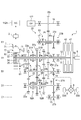
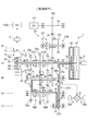
- FIG. 1 It is sectional drawing which shows an example of the vehicle drive device which can apply the control apparatus of this invention.
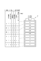
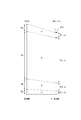
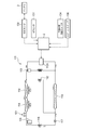
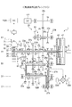
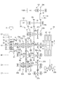
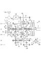
- It is a schematic block diagram of the vehicle drive device of FIG. It is explanatory drawing of a standard control map. It is explanatory drawing of a switching control map. It is explanatory drawing of the control map at the time of battery deterioration. It is a figure which shows roughly the structure of a refrigerating cycle and the control apparatus of this invention. It is a figure at the time of 3rd speed EV driving
- FIG. 1 is a schematic diagram of a vehicle drive device of Patent Document 1.
- the vehicle drive device 1 is for driving drive wheels DW and DW via drive shafts 9 and 9 of a hybrid vehicle (not shown), and is an internal combustion engine (hereinafter referred to as “engine”) as a drive source. 6, an electric motor 7, and a transmission 20 for transmitting power to the drive wheels DW and DW.
- engine an internal combustion engine
- the engine 6 is, for example, a gasoline engine or a diesel engine, and a first clutch 41 and a second clutch 42 of the transmission 20 are connected to a crankshaft 6 a of the engine 6.
- the electric motor 7 is a three-phase brushless DC motor, and has a stator 71 and a rotor 72 disposed so as to face the stator 71, and is disposed on the outer peripheral side of the ring gear 35 of the planetary gear mechanism 30 described later. Yes.
- the rotor 72 is connected to the sun gear 32 of the planetary gear mechanism 30 and is configured to rotate integrally with the sun gear 32 of the planetary gear mechanism 30.
- the planetary gear mechanism 30 includes a sun gear 32, a ring gear 35 that is arranged coaxially with the sun gear 32 and that surrounds the sun gear 32, and a planetary gear 34 that meshes with the sun gear 32 and the ring gear 35.
- the planetary gear 34 has a carrier 36 that can rotate and revolve, and the sun gear 32, the ring gear 35, and the carrier 36 are configured to be differentially rotatable with respect to each other.
- the ring gear 35 is provided with a lock mechanism 61 having a synchronization mechanism and configured to stop (lock) the rotation of the ring gear 35.
- a friction engagement device using a brake and a sleeve may be used as the lock mechanism 61.
- the transmission 20 is a so-called twin clutch transmission that includes the first clutch 41 and the second clutch 42, the planetary gear mechanism 30, and a plurality of transmission gears described later.
- the transmission 20 rotates in parallel with the first main shaft 11, the second main shaft 12, the connecting shaft 13, and the rotation axis A ⁇ b> 1 disposed on the same axis (rotation axis A ⁇ b> 1) as the crankshaft 6 a of the engine 6.
- a counter shaft 14 rotatable about the axis B1, a first intermediate shaft 15 rotatable about a rotation axis C1 parallel to the rotation axis A1, and a rotation axis D1 parallel to the rotation axis A1.
- a second intermediate shaft 16 and a reverse shaft 17 rotatable around a rotation axis E1 disposed in parallel with the rotation axis A1 are provided.
- the first main shaft 11 is provided with a first clutch 41 on the engine 6 side, and the sun gear 32 of the planetary gear mechanism 30 and the rotor 72 of the electric motor 7 rotate integrally with the first main shaft 11 on the side opposite to the engine 6 side. It is provided to do. Accordingly, the first main shaft 11 is selectively connected to the crankshaft 6a of the engine 6 by the first clutch 41 and directly connected to the electric motor 7, so that the power of the engine 6 and / or the electric motor 7 is input. It is configured.
- the second main shaft 12 is configured to be shorter and hollow than the first main shaft 11, and is disposed so as to be relatively rotatable so as to cover the periphery of the first main shaft 11 on the engine 6 side. Further, the second main shaft 12 is provided with a second clutch 42 on the engine 6 side, and an idle drive gear 27a is provided on the opposite side to the engine 6 side so as to rotate integrally with the second main shaft 12. Accordingly, the second main shaft 12 is selectively connected to the crankshaft 6a of the engine 6 by the second clutch 42, and the power of the engine 6 is input to the idle drive gear 27a.
- the connecting shaft 13 is configured to be shorter and hollow than the first main shaft 11, and is disposed so as to be rotatable relative to the first main shaft 11 so as to cover the periphery of the first main shaft 11 on the side opposite to the engine 6 side. Further, a third speed drive gear 23a is provided on the connecting shaft 13 so as to rotate integrally with the connecting shaft 13 on the engine 6 side, and a carrier 36 of the planetary gear mechanism 30 is connected to the opposite side to the engine 6 side. It is provided to rotate integrally with the shaft 13. Therefore, the carrier 36 provided on the connecting shaft 13 and the third-speed drive gear 23a are configured to rotate integrally by the revolution of the planetary gear 34.
- the first main shaft 11 is oddly coupled with the third speed drive gear 23a between the third speed drive gear 23a provided on the connecting shaft 13 and the idle drive gear 27a provided on the second main shaft 12.
- a seventh-speed drive gear 97a and a fifth-speed drive gear 25a constituting the step transmission unit are provided so as to be rotatable relative to the first main shaft 11 in this order from the third-speed drive gear 23a side.
- a reverse driven gear 28b that rotates integrally with the first main shaft 11 is provided between the fifth speed drive gear 25a and the idle drive gear 27a.
- a step-shifting shifter 51A is provided, and a second main shaft 11 and a fifth speed drive gear 25a are connected or released between the seventh speed drive gear 97a and the fifth speed drive gear 25a.
- An odd speed shifter 51B is provided.
- the first main shaft 11 and the third speed drive gear 23a are connected to rotate integrally, and at the seventh speed connection position.
- the first main shaft 11 and the seventh-speed drive gear 97a are connected to rotate integrally, and when the first odd-numbered shift shifter 51A is in the neutral position, the first main shaft 11 is driven to the third speed. It rotates relative to the gear 23a and the seventh speed drive gear 97a.
- the carrier 36 connected to the sun gear 32 provided on the first main shaft 11 and the third speed drive gear 23a by the connecting shaft 13 is provided. While rotating integrally, the ring gear 35 also rotates together, and the planetary gear mechanism 30 is united.
- the first main shaft 11 and the fifth speed driving gear 25a are connected to rotate integrally, and when in the neutral position, the first main shaft 11 is driven to the fifth speed. It rotates relative to the gear 25a.
- the first intermediate shaft 15 is provided with a first idle driven gear 27b that meshes with an idle drive gear 27a provided on the second main shaft 12 so as to rotate integrally with the first intermediate shaft 15.
- the second intermediate shaft 16 is provided with a second idle driven gear 27c that meshes with the first idle driven gear 27b provided on the first intermediate shaft 15 so as to rotate integrally with the second intermediate shaft 16.
- the second idle driven gear 27c constitutes the first idle gear train 27A together with the idle drive gear 27a and the first idle driven gear 27b described above, and the power of the engine 6 is transmitted from the second main shaft 12 via the first idle gear train 27A. Is transmitted to the second intermediate shaft 16.
- the second intermediate shaft 16 has an even number of stages at positions corresponding to the third speed drive gear 23a, the seventh speed drive gear 97a, and the fifth speed drive gear 25a provided on the first main shaft 11, respectively.
- a second speed drive gear 22a, a sixth speed drive gear 96a, and a fourth speed drive gear 24a constituting the speed change portion are provided so as to be rotatable relative to the second intermediate shaft 16.
- a first intermediate shaft 16 and the second-speed drive gear 22a or the sixth-speed drive gear 96a are connected or released between the second-speed drive gear 22a and the sixth-speed drive gear 96a.
- An even speed shifter 52A is provided to connect or release the second intermediate shaft 16 and the fourth speed drive gear 24a between the sixth speed drive gear 96a and the fourth speed drive gear 24a.
- a second even speed shifter 52B is provided.
- the second intermediate shaft 16 and the second speed drive gear 22a are connected and rotated together to form the sixth speed connection position.
- the second intermediate shaft 16 and the sixth speed drive gear 96a are connected to rotate integrally, and when the first even-numbered shift gear shifter 52A is in the neutral position, the second intermediate shaft 16 is in the second position. It rotates relative to the speed drive gear 22a and the sixth speed drive gear 96a.
- the second intermediate shaft 16 and the fourth-speed drive gear 24a are connected to rotate integrally, and when in the neutral position, the second intermediate shaft 16 is in the fourth speed. It rotates relative to the drive gear 24a.
- a first shared driven gear 23b, a second shared driven gear 96b, a third shared driven gear 24b, a parking gear 21, and a final gear 26a are integrated with the counter shaft 14 in order from the side opposite to the engine 6 side. It is provided so as to be rotatable.
- the first shared driven gear 23b meshes with the third speed drive gear 23a provided on the connecting shaft 13 to form the third speed gear 23 together with the third speed drive gear 23a, and the second intermediate gear 23b.
- the second speed gear 22 is configured together with the second speed drive gear 22a by meshing with the second speed drive gear 22a provided on the shaft 16.
- the second shared driven gear 96b meshes with a seventh speed drive gear 97a provided on the first main shaft 11 to form a seventh speed gear 97 together with the seventh speed drive gear 97a. Is engaged with a sixth speed drive gear 96a to form a sixth speed gear 96 together with the sixth speed drive gear 96a.
- the third shared driven gear 24 b meshes with a fifth speed drive gear 25 a provided on the first main shaft 11 to form a fifth speed gear 25 together with the fifth speed drive gear 25 a, and the second intermediate shaft 16.
- the fourth speed gear 24 is configured together with the fourth speed drive gear 24a.
- the final gear 26 a meshes with the differential gear mechanism 8, and the differential gear mechanism 8 is connected to the drive wheels DW and DW via the drive shafts 9 and 9. Therefore, the power transmitted to the counter shaft 14 is output from the final gear 26a to the differential gear mechanism 8, the drive shafts 9, 9, and the drive wheels DW, DW.
- the reverse shaft 17 is provided with a third idle driven gear 27 d that meshes with a first idle driven gear 27 b provided on the first intermediate shaft 15 so as to be rotatable integrally with the reverse shaft 17.
- the third idle driven gear 27d constitutes the second idle gear train 27B together with the idle drive gear 27a and the first idle driven gear 27b described above, and the power of the engine 6 is transmitted from the second main shaft 12 via the second idle gear train 27B. Is transmitted to the reverse shaft 17.
- the reverse shaft 17 is provided with a reverse drive gear 28 a that meshes with a reverse driven gear 28 b provided on the first main shaft 11 so as to be rotatable relative to the reverse shaft 17.
- the reverse drive gear 28a constitutes the reverse gear train 28 together with the reverse driven gear 28b.
- a reverse shifter 53 for connecting or releasing the reverse shaft 17 and the reverse drive gear 28a is provided on the opposite side of the reverse drive gear 28a from the engine 6 side.
- the first and second odd speed shifters 51A and 51B, the first and second even speed shifters 52A and 52B, and the reverse shifter 53 have a synchronization mechanism for matching the rotational speed of the shaft to be connected with the gears.
- the clutch mechanism is used.
- the first and second odd speed shifting shifters 51A and 51B together with the lock mechanism 61 constitute an odd speed switching means, and the first and second even speed shifting shifters 52A and 52B constitute an even speed switching means.
- the transmission 20 configured in this way has a third speed drive gear 23a, a seventh speed drive gear 97a, and a fifth speed drive on the first main shaft 11 which is one of the two speed change shafts.
- An odd-stage transmission unit comprising a gear 25a is configured, and a second-speed drive gear 22a, a sixth-speed drive gear 96a, and a fourth-speed drive gear are provided on the second intermediate shaft 16, which is the other transmission shaft of the two transmission shafts.
- An even-numbered transmission unit composed of the drive gear 24a is configured.
- the vehicle drive device 1 is provided with an electric air-conditioning compressor 112A incorporating a motor different from the electric motor 7 and an oil pump 122.
- the oil pump 122 is mounted on the oil pump auxiliary shaft 19 arranged in parallel with the rotation axes A1 to E1 so as to be integrally rotatable with the oil pump auxiliary shaft 19.
- An oil pump driven gear 28c meshing with the reverse drive gear 28a is attached to the oil pump auxiliary machine shaft 19 so as to be integrally rotatable, and the power of the engine 6 and / or the motor 7 for rotating the first main shaft 11 is transmitted. Is done.
- the vehicle drive device 1 of the present embodiment has the following first to fifth transmission paths.
- the power of the engine 6 is such that the first main shaft 11, the planetary gear mechanism 30, the connecting shaft 13, the third speed gear 23 (the third speed drive gear 23a, the first shared driven gear 23b).
- the reduction gear ratio of the planetary gear mechanism 30 is set so that the engine torque transmitted to the drive wheels DW and DW via the first transmission path corresponds to the first speed. That is, the reduction ratio obtained by multiplying the reduction ratio of the planetary gear mechanism 30 and the reduction ratio of the third speed gear 23 is set to be equivalent to the first speed.
- the first clutch 41 is engaged, the lock mechanism 61 is locked, and the first and second odd speed shifters 51A and 51B are set to neutral so that the first speed traveling is performed.
- the power of the engine 6 is such that the second main shaft 12, the first idle gear train 27A (the idle drive gear 27a, the first idle driven gear 27b, the second idle driven gear 27c), the second intermediate The shaft 16, the second speed gear 22 (second speed drive gear 22a, first shared driven gear 23b) or the fourth speed gear 24 (fourth speed drive gear 24a, third shared driven gear 24b) or second
- the drive wheels DW and DW are driven via the 6-speed gear 96 (the 6th-speed drive gear 96a and the second shared driven gear 96b), the counter shaft 14, the final gear 26a, the differential gear mechanism 8, and the drive shafts 9 and 9. It is a transmission path transmitted to.
- the second clutch 42 is engaged, and the second even speed shifter 52A is in-geared at the second speed connecting position so that the second speed travel is performed.
- the fourth speed travel is performed by in-gearing the shifter 52B, and the sixth speed travel is performed by in-gearing the first even-numbered shift shifter 52A at the sixth speed connection position.
- the power of the engine 6 is such that the first main shaft 11, the third speed gear 23 (the third speed drive gear 23a, the first shared driven gear 23b) or the fifth speed gear 25 ( 5th speed drive gear 25a, 3rd common driven gear 24b) or 7th speed gear 97 (7th speed drive gear 97a, 2nd common driven gear 96b), counter shaft 14, final gear 26a, differential gear
- This is a transmission path that is transmitted to the drive wheels DW and DW via the mechanism 8 and the drive shafts 9 and 9.
- the first clutch 41 is engaged, and the first odd-numbered gear shifter 51A is in-geared at the third-speed connection position, so that the third speed travel is performed, and the second odd-numbered gear shift is performed.
- the fifth speed travel is performed by in-gearing the shifter 51B, and the seventh speed travel is performed by in-gearing the first odd-numbered speed shifter 51A at the seventh speed connection position.
- the power of the electric motor 7 is such that the planetary gear mechanism 30 or the third speed gear 23 (the third speed drive gear 23a, the first shared driven gear 23b) or the fifth speed gear 25 is used.
- a transmission path is transmitted to the drive wheels DW and DW via the gear mechanism 8 and the drive shafts 9 and 9.
- the lock mechanism 61 is locked and the first and second odd speed shifters 51A and 51B are made neutral.
- the first speed EV travel is performed, the lock mechanism 61 is unlocked, and the first odd-numbered speed shifter 51A is in-geared at the third speed connection position, whereby the third speed EV travel is performed, and the lock mechanism 61 is locked.
- the fifth speed EV travel is performed, and the lock mechanism 61 is unlocked and the first odd speed shifter 51A is in-gear at the seventh speed connection position. Then, the seventh speed EV traveling is performed.
- the power of the engine 6 is such that the second main shaft 12, the second idle gear train 27B (the idle drive gear 27a, the first idle driven gear 27b, the third idle driven gear 27d), the reverse shaft 17 , Reverse gear train 28 (reverse drive gear 28a, reverse driven gear 28b), planetary gear mechanism 30, connecting shaft 13, third speed gear 23 (third speed drive gear 23a, first common driven gear 23b) ), A transmission path connected to the drive wheels DW and DW via the counter shaft 14, the final gear 26a, the differential gear mechanism 8, and the drive shafts 9 and 9.
- the second clutch 42 is fastened, the reverse shifter 53 is in-geared at the reverse connection position, and the lock mechanism 61 is locked, so that the reverse travel is performed.
- the motor 7 is connected to the battery 3 via the control device 2 that performs various controls of the entire vehicle so that power supply from the battery 3 and energy regeneration to the battery 3 are performed via the control device 2. It has become. That is, the motor 7 is driven by the electric power supplied from the battery 3 via the control device 2, and performs regenerative power generation by the rotation of the drive wheels DW and DW and the power of the engine 6 at the time of decelerating traveling, thereby generating the battery 3. Can be charged (energy recovery).
- the electric air-conditioning compressor 112A is also connected to the battery 3 via the control device 2, and is PWM-controlled by the control device 2 upon receiving power supply from the battery 3. Further, the control device 2 includes an acceleration request, a braking request, an engine rotation speed, a motor rotation speed, a motor temperature, a rotation speed of the first and second main shafts 11 and 12, a rotation speed of the counter shaft 14 and the like, a vehicle speed, a shift position, While an SOC (State of Charge) or the like is input, a signal for controlling the engine 6, a signal for controlling the motor 7, a signal indicating the power generation state / charge state / discharge state of the battery 3, the first and second odd stages
- the shifter 51A, 51B for shifting, the first and second even shift shifters 52A, 52B, the signal for controlling the reverse shifter 53, the signal for controlling the connection (lock) and release (neutral) of the lock mechanism 61 are output. Is done.
- control device 2 has a standard control map Map1 shown in FIG. 3 and a switching control map Map2 shown in FIG. 4 for determining whether various controls can be performed according to the SOC of the battery 3, and basically, Based on the standard control map Map1, it is determined whether ENG start, idle stop, deceleration regeneration, ENG separation, EV travel, and air conditioner compressor drive are possible.
- ⁇ is executable, ⁇ is prohibited, and ⁇ is conditional.
- the SOC is classified into four zones, C zone, B zone, A zone, and D zone, from the smallest to the largest, and the A zone is further divided into the A to L zones from the smallest to the largest.
- AM zone and AH zone it is divided into 6 zones in total.
- deceleration regeneration and ENG disconnection are allowed under certain conditions, EV travel and idle stop are prohibited in the B zone and C zone, and the AM zone is controlled as the target charge amount.
- the B zone is expanded to the area that was the AL zone in the standard control map Map1.
- the switching control map Map2 has a narrower EV travel permission area than the standard control map Map1.
- each zone of the standard control map Map1 and the switching control map Map2 varies depending on the deterioration of the battery 3.
- the reduction widths of the A zone, the B zone, and the D zone are set to ⁇ %
- the reduction width of the C zone is set to ⁇ %
- ⁇ and ⁇ are always set so that ⁇ ⁇ .
- the reduction widths of the A zone, the B zone, and the D zone are constant here, the reduction widths of the respective zones may be set as appropriate.
- the reduction width of the C zone is always minimized. In this way, by reducing the reduction range of the C zone in which the engine can be started as compared with other zones, the engine 6 is reliably started by the motor 7 even when the SOC of the battery 3 is reduced. be able to.
- the vehicle drive device 1 configured as described above controls the connection and disconnection of the lock mechanism 61, the first and second clutches 41, 42, and the first and second odd-stage shift shifters 51A, 51B, first, By controlling the connection positions of the second even-numbered shift shifters 52A and 52B and the reverse shifter 53, the engine 6 can perform the first to fifth speed travels and the reverse travel.
- the driving force is transmitted to the drive wheels DW and DW through the first transmission path by fastening the first clutch 41 and connecting the lock mechanism 61.
- the second clutch 42 is engaged and the first even shift gear shifter 52A is in-geared at the second speed connecting position so that the driving force is applied to the drive wheels DW and DW via the second transmission path.
- the third speed travel the first clutch 41 is engaged and the first odd-numbered shift shifter 51A is in-geared at the third speed connection position, so that the driving force is supplied to the drive wheels DW via the third transmission path. , DW.
- the driving force is transmitted to the drive wheels DW and DW through the second transmission path by in-gearing the second even speed shifter 52B, and the fifth speed traveling is performed in the second odd speed stage.
- the driving force is transmitted to the drive wheels DW and DW through the third transmission path by in-gearing the shift shifter 51B.
- the second clutch 42 is engaged and the first even-numbered shift shifter 52A is in-geared at the sixth speed connecting position, so that the driving force is supplied to the drive wheels DW
- the driving force is driven through the third transmission path by engaging the first clutch 41 and in-gearing the first odd-numbered shift shifter 51A at the seventh speed connection position. It is transmitted to the wheels DW and DW.
- the second clutch 42 is engaged and the reverse shifter 53 is connected, whereby reverse travel is performed via the fifth transmission path.
- the motor 7 assists by connecting the lock mechanism 61 while the engine is running, or by pre-shifting the first and second odd speed shift shifters 51A and 51B and the first and second even speed shift shifters 52A and 52B.
- the engine 6 can be started by the motor 7 and the battery 3 can be charged even during idling.
- the first and second clutches 41 and 42 can be disconnected and the EV 7 can be driven by the motor 7.
- the first and second clutches 41 and 42 are disconnected, and the lock mechanism 61 is connected to travel through the fourth transmission path, and the first odd-numbered EV mode.
- the shifter for shifting 51A at the third-speed connection position to in-gear the third-speed EV mode that travels via the fourth transmission path and the second odd-numbered shift shifter 51B at the fifth-speed connection position In-gear the shifter for shifting 51A at the third-speed connection position to in-gear the third-speed EV mode that travels via the fourth transmission path and the second odd-numbered shift shifter 51B at the fifth-speed connection position.
- EV mode exists.
- the compressor 112A for the electric air conditioner is driven by using a motor different from the electric motor 7 as a power source, it can be operated regardless of the driving state of the engine 6 or the electric motor 7 and the traveling stage of the transmission 20.
- the third speed EV travel will be described with reference to FIG.
- the motor 7 is driven (torque is applied in the forward rotation direction) in a state where the first odd speed shifter 51A is in-geared at the third speed connection position.
- the planetary gear mechanism 30 connected to the rotor 72 is integrally rotated in the forward rotation direction.
- the power transmitted to the sun gear 32 is not transmitted from the first main shaft 11 to the crankshaft 6a of the engine 6, and the motor torque is
- FIG. 7B EV traveling is performed by being transmitted to the drive wheels DW and DW via the fourth transmission path passing through the third speed gear 23.
- control device 2 If there is an air conditioner operation request during this EV traveling, the control device 2 operates the compressor 112A for the electric air conditioner.
- the refrigeration cycle 111 including the electric air-conditioning compressor 112A includes an outlet of the electric air-conditioning compressor 112A ⁇ oil separator 113 ⁇ condenser 114 ⁇ receiver 115 ⁇ refrigeration valve 116 ⁇ expansion valve 117 ⁇ evaporator as shown in FIG. 118 ⁇ Connected by a refrigerant pipe so that the refrigerant circulates through the path of the suction port of the compressor 112A for the electric air conditioner.
- reference numeral 101 denotes a pressure switch capable of switching the pressure of the refrigerant pipe
- reference numeral 102 denotes a fog removal valve that removes fog adhering to the evaporator 118.
- the high-temperature refrigerant compressed by the electric air-conditioning compressor 112A is sent to the condenser 114, radiates and condenses and liquefies, and then the expansion valve via the receiver 115 and the refrigeration valve 116. 117.
- the expansion valve 117 expands the refrigerant from the liquefied state to form a low-temperature / low-pressure mist, and then the refrigerant is sent to the evaporator 118.
- the refrigerant evaporates in the evaporator 118, the evaporator 118 is cooled by the latent heat of evaporation.
- the wind flowing along the evaporator 118 is cooled and blown out into the passenger compartment.
- the refrigerant vaporized in the evaporator 118 is sucked into the electric air conditioner compressor 112A from the evaporator 118, compressed, sent to the condenser 114 again, and thereafter the above-described operation is repeated.
- the control device 2 that controls the operation / stop of the compressor 112A for the electric air conditioner includes an SOC sensor 130 that detects the SOC of the battery 3, an AP sensor 131 that detects the amount of depression of the accelerator pedal, and a set temperature of the air conditioning temperature (cooling temperature).
- An output signal is read from the air conditioning temperature setting switch 134 to be set, the air conditioner switch 135 to turn on / off the air conditioning operation, etc., and the shift control is performed based on the shift map and the vehicle interior is in the air conditioning operation (while the air conditioner switch 135 is on).
- the operation / stop of the electric air-conditioning compressor 112A is controlled by PWM control so as to adjust the temperature to the set temperature.
- the electric air conditioner compressor 112A continues to operate and the EV travel is prohibited when the SOC further decreases. It is necessary to rush and start the engine 6 from EV traveling and switch to engine traveling.
- the standard control map Map1 since there is not much room in the B zone, there is a risk that even if the engine is running in the B zone, the SOC decreases and the vehicle immediately enters the C zone.
- the control device 2 of the first embodiment changes the control map from the standard control map Map1 to the switching control map Map2 and performs drive control of the vehicle.
- the switching control map Map2 the B zone is expanded to the area that was the AL zone in the standard control map Map1, and therefore, when the SOC of the battery 3 decreases from the AM zone, the engine 6 is started and the engine travels. Therefore, the opportunity to enter the C zone where the B zone becomes wider and the SOC becomes extremely small can be reduced.
- the EV travel permission area is narrowed by switching from the standard control map Map1 to the switching control map Map2, and the engine travels quickly. This makes it difficult for the SOC of the battery 3 to shift to the C zone, so that the SOC of the battery 3 can be managed with a margin.
- priority is given to 2nd speed if it is a region where second speed or third speed travel is possible, and fourth speed travel if it is a region where third speed or fourth speed travel is possible.
- Priority More specifically, when the third speed travel shown in FIG. 8 is selected when the SOC of the battery 3 enters the B zone during the third speed EV travel shown in FIG. 7, the gear ratio of the third speed gear 23 is selected. The motor 7 rotates at the rotation speed of the first main shaft 11 that rotates in accordance with the vehicle speed. When the second speed traveling shown in FIG. 9 is selected, the lock mechanism 61 is connected as shown in FIG.
- the number of rotations of the first main shaft 11 can be increased by the gear ratio of the planetary gear mechanism 30, and the regeneration amount of the motor 7 can be increased.
- the third speed drive gear 23a and the fifth speed drive gear 25a are driven by the first odd speed shift shifter 51A or the second odd speed shift shifter 51B.
- any one of the seventh-speed drive gears 97a can be connected to the first main shaft 11 to charge the first main shaft 11 while reducing the rotation speed.
- the amount of charge is increased by increasing the number of rotations of the first main shaft 11, or the number of rotations of the first main shaft 11 is decreased depending on the situation of the motor 7, etc.
- Various situations can be dealt with by adjusting the shift position with the traveling gear fixed.
- the motor 7 can completely regenerate by releasing the first clutch 41 during deceleration.
- the amount of charge of the motor 7 corresponding to the load of the engine 6 can be increased as compared with the state in which the first clutch 41 is still engaged.
- the engine 6, the motor 7, the battery 3 that supplies power to the motor 7, the motor 7 and the engine 7 are selectively connected via the first clutch 41.
- the first main shaft 11 as the first input shaft connected to the second intermediate shaft 16, the second intermediate shaft 16 as the second input shaft selectively connected to the engine 6 via the second clutch 42, and odd-numbered stage switching means.
- a counter shaft 14 that is selectively connected to the first main shaft 11 through the even-numbered switching means and selectively connected to the second intermediate shaft 16 through the even number switching means, and for the electric air conditioner
- a control device 2 of the vehicle drive device 1 including a compressor 112A, and a standard control map Map1 in which an EV travel permission area is set according to the SOC of the battery 3, and an EV travel of the standard control map Map1.
- a switching control map Map2 having a narrowable range.
- the threshold value of the C zone where the engine can be started by the motor 7 is set lower than the threshold values of the other A zone, B zone, and D zone.
- the vehicle drive device 1 it is necessary to start the engine 6 with the motor 7 when shifting from EV traveling to engine traveling.
- the third speed EV traveling shown in FIG. 7 will be described as an example.
- the engine 6 can be started with the crankshaft 6a.
- power is consumed correspondingly, and the SOC of the battery 3 is reduced. Therefore, it is preferable to suppress frequent switching from EV traveling to engine traveling.
- the control device 2 of the second embodiment is initially driven and controlled based on the standard control map Map1 even if there is an air conditioner operation request.
- the vehicle enters the B zone and shifts to the engine running, the vehicle is controlled by switching from the standard control map Map1 to the switching control map Map2, and the vehicle enters the AM zone again from the B zone.
- drive control of the vehicle is performed based on the original standard control map Map1.
- the next operation is performed on the basis of the standard control map Map1. Since the EV travel is switched to the engine travel when the zone shifts to the B zone, the EV travel possible region can be secured by the AL zone of the standard control map Map1. As a result, switching between EV traveling and engine traveling frequently occurs, and power consumption associated with starting of the engine 6 can be suppressed.
- the engine 6, the motor 7, the battery 3 that supplies power to the motor 7, the motor 7 and the engine 7 are selectively connected via the first clutch 41.
- the first main shaft 11 as the first input shaft connected to the second intermediate shaft 16, the second intermediate shaft 16 as the second input shaft selectively connected to the engine 6 via the second clutch 42, and odd-numbered stage switching means.
- a counter shaft 14 which is selectively connected to the first main shaft 11 through the even number switching means and selectively connected to the second intermediate shaft 16 through the even-numbered switching means, and a compressor for an electric air conditioner.
- the control device 2 of the vehicle drive device 1 including the standard control map Map1 in which the EV travel permission area is set according to the SOC of the battery 3, and the EV travel permission of the standard control map Map1.
- a switching control map Map2 having a narrowed area, and from the AL zone, which is the EV travel permission area, to the B zone, which is the EV travel prohibition area, during the operation of the compressor 112A for the electric air conditioner, the EV travel is changed to the engine travel.
- the standard control map Map1 is switched to the switching control map Map2, and the drive control is performed, and the EV travel prohibition area B zone is entered again into the EV travel permission area AM zone, and the EV travel from the engine travel is performed.
- the drive control is carried out by switching from the switching control map Map2 to the standard control map Map1, and thus switching between EV traveling and internal combustion engine traveling frequently occurs, and the consumption of electric power accompanying the start of the internal combustion engine is suppressed. be able to.
- the threshold value of the C zone where the engine can be started by the motor 7 is smaller than the threshold values of the other A zone, B zone, and D zone.
- FIG. 12 is a cross-sectional view showing another vehicle drive device to which the control device of the present invention can be applied
- FIG. 13 is a schematic configuration diagram of the vehicle drive device of FIG.
- This vehicle drive device 1A is provided with an air conditioner compressor 112B operable by power transmitted from the transmission 20, instead of the electric air conditioner compressor 112A.
- the air conditioner compressor 112B is provided via an air conditioner clutch 121 on the air conditioner auxiliary shaft 18 arranged in parallel with the rotation axes A1 to E1.
- an air conditioner driven gear 29b to which power is transmitted via a chain 29c from an air conditioner drive gear 29a provided in the oil pump auxiliary shaft 19 is rotatable together with the air conditioner auxiliary shaft 18.
- the power of the engine 6 and / or motor 7 is transmitted from the auxiliary shaft 19 for the oil pump through the air conditioner transmission mechanism 29 including the air conditioner drive gear 29a, the chain 29c, and the air conditioner driven gear 29b.
- the air conditioner compressor 112B is configured such that power transmission can be interrupted by connecting and disconnecting the air conditioner clutch 121 by an air conditioner operating solenoid (not shown).
- this air conditioner compressor 112B is connected to the first main shaft 11, the first main shaft 11 inevitably rotates while traveling with an odd number of gears, so that the air conditioner compressor 112 can be operated.
- the air conditioner compressor 112 In order to operate the air conditioner compressor 112 while traveling in gear, either (i) the odd-numbered stage switching means is made neutral and the motor 7 is rotated by the motor 7, or (ii) either of the odd-numbered stage switching means.
- the air conditioner clutch 121B can be engaged and the air conditioner compressor 112B can be operated regardless of whether the vehicle is traveling at the odd-numbered transmission unit or the even-numbered transmission unit. .
- the air conditioner clutch 121 When there is an air conditioner operation request during this EV traveling, the air conditioner clutch 121 is engaged by the control device 2, and the rotation of the first main shaft 11 is transmitted as described above to operate the air conditioner compressor 112B.
- the control map is displayed when there is an air conditioner operation request, as in the first embodiment.
- the vehicle travels from the AL zone, which is the EV travel permission area, to the B zone, which is the EV travel prohibition area, and shifts from EV travel to engine travel.
- the standard control map Map1 is switched to the switching control map Map2, and the drive control is performed, and the EV travel prohibition area B zone is again entered into the EV travel permission area AM zone and the engine travel is shifted to the EV travel.
- the driving control is performed by switching from the switching control map Map2 to the standard control map Map1, thereby frequently switching between EV traveling and internal combustion engine traveling, thereby suppressing power consumption associated with starting of the internal combustion engine. Can do.
- the cooling performance obtained from the rotational speed of the air-conditioner compressor 112B is higher than the required cooling performance from the air-conditioning temperature setting switch 134 even when switched to the switching control map Map2, and PWM control is performed.
- the control device 2 may switch from the switching control map Map2 to the standard control map Map1. That is, when the cooling performance obtained from the rotation speed of the air conditioner compressor 112B is higher than the required cooling performance and there is a margin for the cooling performance, drive control is performed based on the standard control map Map1 without narrowing the EV travel permission area.
- the improvement in fuel consumption by EV traveling can be effectively utilized.
- the cooling performance obtained from the rotational speed of the air conditioner compressor 112B is lower than the required cooling performance by a predetermined deviation or more
- the number of rotations of the first main shaft 11 to which the air conditioner compressor 112B is connected is changed from the state of the second speed traveling 3-speed preshift shown in FIG. 11 to the state of the second speed traveling 1-speed preshift shown in FIG.
- the cooling performance of the air conditioner compressor B can be increased.
- the vehicle drive device 1 has an odd-numbered stage gear disposed on a first main shaft 11 that is an input shaft to which a motor 7 of a twin clutch transmission is connected, and a second input shaft that is not connected to the motor 7.
- the even-numbered gear is arranged on the intermediate shaft 16
- the present invention is not limited to this.
- An even-numbered gear is arranged on the first main shaft 11 that is the input shaft to which the motor 7 is connected, and the input shaft is not connected to the motor 7.
- An odd-numbered gear may be arranged on a certain second intermediate shaft 16.
- a first common driven gear 23b, a fourth speed drive gear 24a, and a fifth speed are configured such that the driven gear attached to the counter shaft 14 is meshed with the second speed driving gear 22a and the third speed driving gear 23a.
- the third shared driven gear 24b meshed with the speed drive gear 25a and the second shared driven gear 96b meshed with the sixth speed drive gear 96a and the seventh speed drive gear 97a are combined, Not limited to this, a plurality of driven gears that mesh with the respective gears may be provided.
- the planetary gear mechanism 30 is exemplified as the first speed drive gear, but the present invention is not limited to this, and the first speed drive gear may be provided in the same manner as the third speed drive gear 23a.
- the planetary gear mechanism 30 serving as the first speed drive gear, the third speed drive gear 23a, the fifth speed drive gear 25a, and the seventh speed drive gear 97a are provided as odd-numbered speed stages. It may be added or the number of gears may be reduced. Similarly, other gears may be added to the second-speed drive gear 22a, the fourth-speed drive gear 24a, and the sixth-speed drive gear 96a as even-numbered gears, or the number of gears may be reduced.
- FIG. 14 is a schematic configuration diagram of a vehicle drive device 1B including a transmission 20A having five speeds and a compressor 112A for an electric air conditioner
- FIG. 15 is a diagram illustrating the transmission 20A and the gears having five speeds.
- It is a schematic block diagram of the vehicle drive device 1C provided with the air-conditioner compressor 112B which can be operated with the motive power transmitted from the machine 20A.
- symbol is attached
- the sixth speed gear 96 and the seventh speed gear 97 are not provided, and the odd speed shifter 51 shifts in gear at the third speed connection position.
- the first main shaft 11 and the third speed drive gear 23a are connected and rotated together and in-gear at the fifth speed connection position
- the first main shaft 11 and the fifth speed drive gear 25a are connected and integrated.
- the second intermediate shaft 16 and the second speed drive gear 22a are connected and rotated together to form the fourth speed connection position.
- the second intermediate shaft 16 and the fourth speed drive gear 24a are connected to rotate integrally.
- Vehicle drive device 2 Control device 3 Battery (power storage means) 6 Engine (Internal combustion engine) 7 Motor (electric motor) 11 First spindle (first input shaft) 14 Counter shaft (output shaft) 16 Second intermediate shaft (second input shaft) 20, 20A Transmission (transmission mechanism) 22a 2nd speed drive gear 23a 3rd speed drive gear 23b 1st shared driven gear 24a 4th speed drive gear 24b 3rd shared driven gear 25a 5th speed drive gear 30 planetary gear mechanism 41 1st clutch (1 connection means) 42 Second clutch (second connecting / disconnecting means) 51 Shifter for odd-numbered gear shifting (first switching device) 51A 1st odd speed shifter (first switching device) 51B Second odd speed shifter (first switching device) 52 Even-speed shifter (second switching device) 52A 1st even speed shifter (second switching device) 52B Second even speed shifter (second switching device) 61 Locking mechanism (first switching device) 112A, 112B Air-conditioner compressor 121 Air-conditioner clutch Map1 Standard control
Landscapes
- Engineering & Computer Science (AREA)
- Transportation (AREA)
- Mechanical Engineering (AREA)
- Chemical & Material Sciences (AREA)
- Combustion & Propulsion (AREA)
- Power Engineering (AREA)
- Automation & Control Theory (AREA)
- Life Sciences & Earth Sciences (AREA)
- Sustainable Development (AREA)
- Sustainable Energy (AREA)
- Hybrid Electric Vehicles (AREA)
- Electric Propulsion And Braking For Vehicles (AREA)
- Control Of Transmission Device (AREA)
- Air-Conditioning For Vehicles (AREA)
Abstract
Description
内燃機関(例えば、後述の実施形態のエンジン6)と、
電動機(例えば、後述の実施形態のモータ7)と、
前記電動機に電力を供給する蓄電装置(例えば、後述の実施形態のバッテリ3)と、
前記電動機に接続されるとともに第1断接手段(例えば、後述の実施形態の第1クラッチ41)を介して選択的に前記内燃機関に接続される第1入力軸(例えば、後述の実施形態の第1主軸11)と、第2断接手段(例えば、後述の実施形態の第2クラッチ42)を介して選択的に前記内燃機関に接続される第2入力軸(例えば、後述の実施形態の第2中間軸16)と、第1切替装置(例えば、後述の実施形態のロック機構61、第1奇数段変速用シフター51A、第2奇数段変速用シフター51B、奇数段変速用シフター51)を介して選択的に前記第1入力軸に連結されるとともに第2切替装置(例えば、後述の実施形態の第1偶数段変速用シフター52A、第2偶数段変速用シフター52B、偶数段変速用シフター52)を介して選択的に前記第2入力軸に連結される出力軸(例えば、後述の実施形態のカウンタ軸14)と、を備えた変速機構(例えば、後述の実施形態の変速機20、20A)と、
エアコン用コンプレッサ(例えば、後述の実施形態のエアコン用コンプレッサ112A、112B)と、を備える車両用駆動装置(例えば、後述の実施形態の車両用駆動装置1、1A、1B、1C)の制御装置(例えば、後述の実施形態の制御装置2)であって、
前記蓄電装置のSOCに応じてEV走行許可領域が設定された第1のマップ(例えば、後述の実施形態の標準制御マップMap1)と、前記第1のマップのEV走行許可領域を狭くした第2のマップ(例えば、後述の実施形態の切替制御マップMap2)と、を備え、
前記エアコン用コンプレッサの作動時には、前記第1のマップから前記第2のマップに持ち替えて駆動制御することを特徴とする。
内燃機関(例えば、後述の実施形態のエンジン6)と、
電動機(例えば、後述の実施形態のモータ7)と、
前記電動機に電力を供給する蓄電装置(例えば、後述の実施形態のバッテリ3)と、
前記電動機に接続されるとともに第1断接手段(例えば、後述の実施形態の第1クラッチ41)を介して選択的に前記内燃機関に接続される第1入力軸(例えば、後述の実施形態の第1主軸11)と、第2断接手段(例えば、後述の実施形態の第2クラッチ42)を介して選択的に前記内燃機関に接続される第2入力軸(例えば、後述の実施形態の第2中間軸16)と、第1切替装置(例えば、後述の実施形態のロック機構61、第1奇数段変速用シフター51A、第2奇数段変速用シフター51B、奇数段変速用シフター51)を介して選択的に前記第1入力軸に連結されるとともに第2切替装置(例えば、後述の実施形態の第1偶数段変速用シフター52A、第2偶数段変速用シフター52B、偶数段変速用シフター52)を介して選択的に前記第2入力軸に連結される出力軸(例えば、後述の実施形態のカウンタ軸14)と、を備えた変速機構(例えば、後述の実施形態の変速機20、20A)と、
エアコン用コンプレッサ(例えば、後述の実施形態のエアコン用コンプレッサ112A、112B)と、を備える車両用駆動装置(例えば、後述の実施形態の車両用駆動装置1、1A、1B、1C)の制御装置(例えば、後述の実施形態の制御装置2)であって、
前記蓄電装置のSOCに応じてEV走行許可領域が設定された第1のマップ(例えば、後述の実施形態の標準制御マップMap1)と、前記第1のマップのEV走行許可領域を狭くした第2のマップ(例えば、後述の実施形態の切替制御マップMap2)と、を備え、
前記エアコン用コンプレッサの作動中に前記EV走行許可領域からEV走行禁止領域に入ってEV走行から内燃機関走行に移行する場合には、前記第1のマップから前記第2のマップに持ち替えて駆動制御し、
再度前記EV走行禁止領域から前記EV走行許可領域に入って内燃機関走行からEV走行に移行する場合には、前記第2のマップから前記第1のマップに持ち替えて駆動制御することを特徴とする。
前記蓄電装置の劣化が起こったとき、前記電動機による前記内燃機関の始動が可能な最下限ゾーンの閾値の下げ幅を他のゾーンの閾値の下げ幅より小さく設定し、前記電動機により前記内燃機関の始動ができるように前記最下限ゾーンを確保することを特徴とする。
前記EV走行から前記内燃機関走行に移行した場合、変速マップを充電優先モードに変更することを特徴とする。
前記エアコン用コンプレッサは、前記蓄電装置から電力を供給されて駆動する電動エアコン用コンプレッサであることを特徴とする。
前記エアコン用コンプレッサは、エアコン用クラッチ(例えば、後述の実施形態のエアコン用クラッチ121)を介して前記第1入力軸に連結されることを特徴とする。
前記第2のマップに基づいて駆動制御中であって、要求冷却性能に比べ前記エアコン用コンプレッサの冷却性能が高く、PWM制御のオフタイミングが所定以上ある場合には、前記第2のマップから前記第1のマップに戻すことを特徴とする。
要求冷却性能に比べ前記エアコン用コンプレッサの冷却性能が所定偏差以上低い場合には、要求冷却性能を満たすように前記第1入力軸の回転数をあげるように変速を行なうか、又は走行ギヤを変えずに前記第1切替装置をシフトすることを特徴とする。
第3速EVモードは、前述したように第1奇数段変速用シフター51Aを第3速用接続位置にインギヤした状態で、モータ7を駆動(正転方向にトルクを印加)することにより、図7(a)に示すように、ロータ72に接続された遊星歯車機構30は一体で正転方向に回転する。このとき、第1及び第2クラッチ41、42が切断されているため、サンギヤ32に伝達された動力は第1主軸11からエンジン6のクランク軸6aに伝達されることはなく、モータトルクが、図7(b)に示すように、第3速用ギヤ23を通る第4伝達経路を介して駆動輪DW,DWに伝達されEV走行がなされる。
そこで第1実施形態の制御装置2は、エアコン作動要求があると制御マップを標準制御マップMap1から切替制御マップMap2に持ち替えて車両の駆動制御を行なうこととしている。この切替制御マップMap2は、標準制御マップMap1でA-Lゾーンであった領域までBゾーンが拡大されているので、バッテリ3のSOCがA-Mゾーンから減少するとエンジン6を始動してエンジン走行に移行するため、Bゾーンが広くなってSOCが極めて少なくなるCゾーンへの突入する機会を少なくすることができる。このように、本実施形態では、比較的負荷の大きい電動エアコン用コンプレッサ112Aの作動要求があると、標準制御マップMap1から切替制御マップMap2に持ち替えることでEV走行許可領域を狭めて早めにエンジン走行を行い、これによりバッテリ3のSOCがCゾーンに移行しずらくしてバッテリ3のSOCの管理に余裕を持たせることができる。
そこで第2実施形態の制御装置2としては、第1実施形態とは異なり、エアコン作動要求があっても当初は標準制御マップMap1に基づいて駆動制御するものの、一度EV走行中にA-LゾーンからBゾーンに突入してエンジン走行に移行した場合に、標準制御マップMap1から切替制御マップMap2に持ち替えて車両制御を行なうこととし、再度BゾーンからA-Mゾーンに突入してエンジン走行からEV走行に移行する場合は、元の標準制御マップMap1に基づいて車両の駆動制御を行なうこととしている。
例えば、車両用駆動装置1は、ツインクラッチ式変速機のモータ7が接続された入力軸である第1主軸11に奇数段ギヤを配置し、モータ7が接続されていない入力軸である第2中間軸16に偶数段ギヤを配置したが、これに限定されず、モータ7が接続された入力軸である第1主軸11に偶数段ギヤを配置し、モータ7が接続されていない入力軸である第2中間軸16に奇数段ギヤを配置してもよい。
2 制御装置
3 バッテリ(蓄電手段)
6 エンジン(内燃機関)
7 モータ(電動機)
11 第1主軸(第1入力軸)
14 カウンタ軸(出力軸)
16 第2中間軸(第2入力軸)
20、20A 変速機(変速機構)
22a 第2速用駆動ギヤ
23a 第3速用駆動ギヤ
23b 第1共用従動ギヤ
24a 第4速用駆動ギヤ
24b 第3共用従動ギヤ
25a 第5速用駆動ギヤ
30 遊星歯車機構
41 第1クラッチ(第1断接手段)
42 第2クラッチ(第2断接手段)
51 奇数段変速用シフター(第1切替装置)
51A 第1奇数段変速用シフター(第1切替装置)
51B 第2奇数段変速用シフター(第1切替装置)
52 偶数段変速用シフター(第2切替装置)
52A 第1偶数段変速用シフター(第2切替装置)
52B 第2偶数段変速用シフター(第2切替装置)
61 ロック機構(第1切替装置)
112A、112B エアコン用コンプレッサ
121 エアコン用クラッチ
Map1 標準制御マップ
Map2 切替制御マップ
Claims (8)
- 内燃機関と、
電動機と、
前記電動機に電力を供給する蓄電装置と、
前記電動機に接続されるとともに第1断接手段を介して選択的に前記内燃機関に接続される第1入力軸と、第2断接手段を介して選択的に前記内燃機関に接続される第2入力軸と、第1切替装置を介して選択的に前記第1入力軸に連結されるとともに第2切替装置を介して選択的に前記第2入力軸に連結される出力軸と、を備えた変速機構と、
エアコン用コンプレッサと、
を備える車両用駆動装置の制御装置であって、
前記蓄電装置のSOCに応じてEV走行許可領域が設定された第1のマップと、前記第1のマップのEV走行許可領域を狭くした第2のマップと、を備え、
前記エアコン用コンプレッサの作動時には、前記第1のマップから前記第2のマップに持ち替えて駆動制御することを特徴とする車両用駆動装置の制御装置。 - 内燃機関と、
電動機と、
前記電動機に電力を供給する蓄電装置と、
前記電動機に接続されるとともに第1断接手段を介して選択的に前記内燃機関に接続される第1入力軸と、第2断接手段を介して選択的に前記内燃機関に接続される第2入力軸と、第1切替装置を介して選択的に前記第1入力軸に連結されるとともに第2切替装置を介して選択的に前記第2入力軸に連結される出力軸と、を備えた変速機構と、
エアコン用コンプレッサと、
を備える車両用駆動装置の制御装置であって、
前記蓄電装置のSOCに応じてEV走行許可領域が設定された第1のマップと、前記第1のマップのEV走行許可領域を狭くした第2のマップと、を備え、
前記エアコン用コンプレッサの作動中に前記EV走行許可領域からEV走行禁止領域に入ってEV走行から内燃機関走行に移行する場合には、前記第1のマップから前記第2のマップに持ち替えて駆動制御し、
再度前記EV走行禁止領域からEV走行許可領域に入って前記内燃機関走行から前記EV走行に移行する場合には、前記第2のマップから前記第1のマップに持ち替えて駆動制御することを特徴とする車両用駆動装置の制御装置。 - 前記蓄電装置の劣化が起こったとき、前記電動機による前記内燃機関の始動が可能な最下限ゾーンの閾値の下げ幅を他のゾーンの閾値の下げ幅より小さく設定し、前記電動機により前記内燃機関の始動ができるように前記最下限ゾーンを確保することを特徴とする請求項1又は2に記載の車両用駆動装置の制御装置。
- 前記EV走行から前記内燃機関走行に移行した場合、変速マップを充電優先モードに変更することを特徴とする請求項1~3のいずれか1項に記載の車両用駆動装置の制御装置。
- 前記エアコン用コンプレッサは、前記蓄電装置から電力を供給されて駆動する電動エアコン用コンプレッサであることを特徴とする請求項1~4のいずれか1項に記載の車両用駆動装置の制御装置。
- 前記エアコン用コンプレッサは、エアコン用クラッチを介して前記第1入力軸に連結されることを特徴とする請求項1~4のいずれか1項に記載の車両用駆動装置の制御装置。
- 前記第2のマップに基づいて駆動制御中であって、要求冷却性能に比べ前記エアコン用コンプレッサの冷却性能が高く、PWM制御のオフタイミングが所定以上ある場合には、前記第2のマップから前記第1のマップに戻すことを特徴とする請求項6に記載の車両用駆動装置の制御装置。
- 要求冷却性能に比べ前記エアコン用コンプレッサの冷却性能が所定偏差以上低い場合には、要求冷却性能を満たすように前記第1入力軸の回転数をあげるように変速を行なうか、又は走行ギヤを変えずに前記第1切替装置をシフトすることを特徴とする請求項6に記載の車両用駆動装置の制御装置。
Priority Applications (5)
| Application Number | Priority Date | Filing Date | Title |
|---|---|---|---|
| RU2013142346/11A RU2542849C1 (ru) | 2011-02-18 | 2011-11-04 | Блок управления для системы привода транспортного средства |
| CN201180067670XA CN103380045A (zh) | 2011-02-18 | 2011-11-04 | 车辆用驱动装置的控制装置 |
| BR112013020955A BR112013020955A2 (pt) | 2011-02-18 | 2011-11-04 | unidade de controle para sistema de condução de veículo |
| DE112011104907T DE112011104907T5 (de) | 2011-02-18 | 2011-11-04 | Steuereinheit für Fahrzeugantriebssystem |
| US13/985,113 US8983702B2 (en) | 2010-03-31 | 2011-11-04 | Control unit for vehicle driving system |
Applications Claiming Priority (2)
| Application Number | Priority Date | Filing Date | Title |
|---|---|---|---|
| JP2011-032913 | 2011-02-18 | ||
| JP2011032913A JP2011225206A (ja) | 2010-03-31 | 2011-02-18 | 車両用駆動装置の制御装置 |
Publications (1)
| Publication Number | Publication Date |
|---|---|
| WO2012111197A1 true WO2012111197A1 (ja) | 2012-08-23 |
Family
ID=46675748
Family Applications (1)
| Application Number | Title | Priority Date | Filing Date |
|---|---|---|---|
| PCT/JP2011/075457 Ceased WO2012111197A1 (ja) | 2010-03-31 | 2011-11-04 | 車両用駆動装置の制御装置 |
Country Status (7)
| Country | Link |
|---|---|
| US (1) | US8983702B2 (ja) |
| JP (1) | JP2011225206A (ja) |
| CN (1) | CN103380045A (ja) |
| BR (1) | BR112013020955A2 (ja) |
| DE (1) | DE112011104907T5 (ja) |
| RU (1) | RU2542849C1 (ja) |
| WO (1) | WO2012111197A1 (ja) |
Families Citing this family (16)
| Publication number | Priority date | Publication date | Assignee | Title |
|---|---|---|---|---|
| CN102803038B (zh) * | 2010-03-31 | 2015-05-20 | 本田技研工业株式会社 | 混合动力车辆 |
| JP6114128B2 (ja) * | 2013-07-05 | 2017-04-12 | 本田技研工業株式会社 | 自動変速装置 |
| US9758170B2 (en) * | 2015-09-28 | 2017-09-12 | Ford Global Technologies, Llc | Coordinated control of transmission and accessories |
| DE102016005115B3 (de) * | 2016-04-28 | 2017-08-24 | Audi Ag | Verfahren zum Steuern einer Energiespeichereinrichtung eines Mild-Hybrid-Kraftfahrzeugs sowie Ladezustandssteuereinrichtung |
| KR101916073B1 (ko) * | 2016-10-21 | 2018-11-07 | 현대자동차 주식회사 | 하이브리드 전기자동차의 동력전달장치 |
| CN106678353B (zh) * | 2016-12-28 | 2018-07-24 | 上海汽车集团股份有限公司 | 加强暖风的车辆变速器换挡控制方法 |
| JP2018114874A (ja) * | 2017-01-19 | 2018-07-26 | トヨタ自動車株式会社 | ハイブリッド自動車 |
| US10570832B2 (en) | 2017-08-16 | 2020-02-25 | Paccar Inc | Systems and methods for controlling torque in a vehicle |
| JP2019170005A (ja) * | 2018-03-22 | 2019-10-03 | 本田技研工業株式会社 | モータユニット及び車両 |
| JP2019174235A (ja) * | 2018-03-28 | 2019-10-10 | 本田技研工業株式会社 | 電動車両 |
| US11255290B2 (en) * | 2018-03-30 | 2022-02-22 | Honda Motor Co., Ltd. | Internal combustion engine management system, server device, and internal combustion engine management method |
| DE102019202970A1 (de) * | 2019-03-05 | 2020-09-10 | Zf Friedrichshafen Ag | Getriebeanordnung, Antriebsstrang und Verfahren zu dessen Betreiben |
| JP7184008B2 (ja) | 2019-10-02 | 2022-12-06 | トヨタ自動車株式会社 | ハイブリッド車両の制御装置 |
| CN112977163A (zh) * | 2019-12-13 | 2021-06-18 | 中车时代电动汽车股份有限公司 | 电辅助制动优化方法及装置 |
| CN114714886B (zh) * | 2021-01-05 | 2025-10-21 | 广州汽车集团股份有限公司 | 两档混合动力耦合机构、控制系统及控制方法 |
| CN116706973B (zh) * | 2023-08-09 | 2024-02-02 | 深圳康普盾科技股份有限公司 | 一种基于多维度分析的储能电池控制方法、系统及介质 |
Citations (4)
| Publication number | Priority date | Publication date | Assignee | Title |
|---|---|---|---|---|
| JP2000050412A (ja) * | 1998-07-24 | 2000-02-18 | Mazda Motor Corp | ハイブリッド自動車 |
| JP2009067162A (ja) * | 2007-09-11 | 2009-04-02 | Toyota Motor Corp | ハイブリッド車両用駆動装置の制御装置 |
| JP2010221853A (ja) * | 2009-03-24 | 2010-10-07 | Nissan Motor Co Ltd | ハイブリッド車両のモード切換制御装置 |
| JP2011025838A (ja) * | 2009-07-27 | 2011-02-10 | Honda Motor Co Ltd | 動力出力装置の制御装置 |
Family Cites Families (8)
| Publication number | Priority date | Publication date | Assignee | Title |
|---|---|---|---|---|
| DE10165097B3 (de) | 2000-07-18 | 2015-07-23 | Schaeffler Technologies AG & Co. KG | Doppelkupplungsgetriebe |
| CN2657974Y (zh) * | 2003-06-25 | 2004-11-24 | 华南理工大学 | 混合动力电动汽车的混联式动力总成 |
| US7665557B2 (en) * | 2005-06-16 | 2010-02-23 | Eaton Corporation | Hybrid electric powertrain with anti-idle function |
| JP4155321B2 (ja) * | 2006-09-25 | 2008-09-24 | トヨタ自動車株式会社 | ハイブリッド車両の表示装置、ハイブリッド車両、およびハイブリッド車両の表示方法 |
| JP5162998B2 (ja) * | 2006-10-12 | 2013-03-13 | 日産自動車株式会社 | ハイブリッド車両のモード切り替え制御装置 |
| JP5088058B2 (ja) * | 2006-12-26 | 2012-12-05 | 日産自動車株式会社 | ハイブリッド車両のモード切り替え制御装置 |
| JP5363899B2 (ja) | 2009-07-31 | 2013-12-11 | 株式会社トランストロン | 吸気系制御装置、吸気系制御方法 |
| US8210828B2 (en) * | 2010-03-30 | 2012-07-03 | Ford Global Technologies, Llc | Methods and systems for assisted direct start control |
-
2011
- 2011-02-18 JP JP2011032913A patent/JP2011225206A/ja active Pending
- 2011-11-04 US US13/985,113 patent/US8983702B2/en active Active
- 2011-11-04 CN CN201180067670XA patent/CN103380045A/zh active Pending
- 2011-11-04 RU RU2013142346/11A patent/RU2542849C1/ru not_active IP Right Cessation
- 2011-11-04 DE DE112011104907T patent/DE112011104907T5/de not_active Withdrawn
- 2011-11-04 WO PCT/JP2011/075457 patent/WO2012111197A1/ja not_active Ceased
- 2011-11-04 BR BR112013020955A patent/BR112013020955A2/pt not_active Application Discontinuation
Patent Citations (4)
| Publication number | Priority date | Publication date | Assignee | Title |
|---|---|---|---|---|
| JP2000050412A (ja) * | 1998-07-24 | 2000-02-18 | Mazda Motor Corp | ハイブリッド自動車 |
| JP2009067162A (ja) * | 2007-09-11 | 2009-04-02 | Toyota Motor Corp | ハイブリッド車両用駆動装置の制御装置 |
| JP2010221853A (ja) * | 2009-03-24 | 2010-10-07 | Nissan Motor Co Ltd | ハイブリッド車両のモード切換制御装置 |
| JP2011025838A (ja) * | 2009-07-27 | 2011-02-10 | Honda Motor Co Ltd | 動力出力装置の制御装置 |
Also Published As
| Publication number | Publication date |
|---|---|
| DE112011104907T5 (de) | 2013-11-14 |
| US20130325237A1 (en) | 2013-12-05 |
| JP2011225206A (ja) | 2011-11-10 |
| US8983702B2 (en) | 2015-03-17 |
| BR112013020955A2 (pt) | 2016-10-11 |
| CN103380045A (zh) | 2013-10-30 |
| RU2542849C1 (ru) | 2015-02-27 |
Similar Documents
| Publication | Publication Date | Title |
|---|---|---|
| WO2012111197A1 (ja) | 車両用駆動装置の制御装置 | |
| RU2518144C2 (ru) | Гибридное транспортное средство | |
| CN102762402B (zh) | 混合动力车辆用驱动装置 | |
| JP5619142B2 (ja) | 車両用駆動装置 | |
| WO2011021517A1 (ja) | ハイブリッド車両のエンジン始動制御装置 | |
| WO2010110343A1 (ja) | 動力伝達装置 | |
| JP5309000B2 (ja) | ハイブリッド車両 | |
| JP2011213166A (ja) | ハイブリッド車両用駆動装置 | |
| JP2013169831A (ja) | ハイブリット車両 | |
| JP5759835B2 (ja) | ハイブリッド車両の制御装置及び制御方法 | |
| JP5203312B2 (ja) | 動力出力装置の制御装置 | |
| CN102444713B (zh) | 电动机械式自动变速装置、汽车及其变速控制方法 | |
| CN201816450U (zh) | 电动机械式自动变速装置及其汽车 | |
| JP2011213163A (ja) | 車両用駆動装置の制御装置 | |
| JP5557684B2 (ja) | 車両用駆動装置の制御装置 | |
| JP2011213159A (ja) | 車両用駆動装置の制御装置 | |
| JP2011230742A (ja) | ハイブリッド車両 | |
| JP2011213164A (ja) | 車両用駆動装置の制御装置 | |
| JP5698998B2 (ja) | 車両用駆動装置 | |
| JP2018157675A (ja) | 輸送機器の制御装置 | |
| JP2011213165A (ja) | 車両用駆動装置の制御装置 | |
| JP2011213160A (ja) | 車両用駆動装置の制御装置 | |
| JP5932460B2 (ja) | ハイブリッド車両の制御装置 | |
| JP5481344B2 (ja) | 車両用駆動装置の制御装置 | |
| JP2011213162A (ja) | 車両用駆動装置の制御装置 |
Legal Events
| Date | Code | Title | Description |
|---|---|---|---|
| 121 | Ep: the epo has been informed by wipo that ep was designated in this application |
Ref document number: 11858726 Country of ref document: EP Kind code of ref document: A1 |
|
| WWE | Wipo information: entry into national phase |
Ref document number: 13985113 Country of ref document: US |
|
| WWE | Wipo information: entry into national phase |
Ref document number: 112011104907 Country of ref document: DE Ref document number: 1120111049072 Country of ref document: DE |
|
| ENP | Entry into the national phase |
Ref document number: 2013142346 Country of ref document: RU Kind code of ref document: A |
|
| REG | Reference to national code |
Ref country code: BR Ref legal event code: B01A Ref document number: 112013020955 Country of ref document: BR |
|
| 122 | Ep: pct application non-entry in european phase |
Ref document number: 11858726 Country of ref document: EP Kind code of ref document: A1 |
|
| ENP | Entry into the national phase |
Ref document number: 112013020955 Country of ref document: BR Kind code of ref document: A2 Effective date: 20130816 |