WO2012111181A1 - 摩擦攪拌接合装置 - Google Patents
摩擦攪拌接合装置 Download PDFInfo
- Publication number
- WO2012111181A1 WO2012111181A1 PCT/JP2011/062213 JP2011062213W WO2012111181A1 WO 2012111181 A1 WO2012111181 A1 WO 2012111181A1 JP 2011062213 W JP2011062213 W JP 2011062213W WO 2012111181 A1 WO2012111181 A1 WO 2012111181A1
- Authority
- WO
- WIPO (PCT)
- Prior art keywords
- workpiece
- tool
- stir welding
- friction stir
- shoulder
- Prior art date
Links
Images


Classifications
-
- B—PERFORMING OPERATIONS; TRANSPORTING
- B23—MACHINE TOOLS; METAL-WORKING NOT OTHERWISE PROVIDED FOR
- B23K—SOLDERING OR UNSOLDERING; WELDING; CLADDING OR PLATING BY SOLDERING OR WELDING; CUTTING BY APPLYING HEAT LOCALLY, e.g. FLAME CUTTING; WORKING BY LASER BEAM
- B23K20/00—Non-electric welding by applying impact or other pressure, with or without the application of heat, e.g. cladding or plating
- B23K20/12—Non-electric welding by applying impact or other pressure, with or without the application of heat, e.g. cladding or plating the heat being generated by friction; Friction welding
- B23K20/122—Non-electric welding by applying impact or other pressure, with or without the application of heat, e.g. cladding or plating the heat being generated by friction; Friction welding using a non-consumable tool, e.g. friction stir welding
- B23K20/1245—Non-electric welding by applying impact or other pressure, with or without the application of heat, e.g. cladding or plating the heat being generated by friction; Friction welding using a non-consumable tool, e.g. friction stir welding characterised by the apparatus
- B23K20/1255—Tools therefor, e.g. characterised by the shape of the probe
-
- B—PERFORMING OPERATIONS; TRANSPORTING
- B23—MACHINE TOOLS; METAL-WORKING NOT OTHERWISE PROVIDED FOR
- B23K—SOLDERING OR UNSOLDERING; WELDING; CLADDING OR PLATING BY SOLDERING OR WELDING; CUTTING BY APPLYING HEAT LOCALLY, e.g. FLAME CUTTING; WORKING BY LASER BEAM
- B23K20/00—Non-electric welding by applying impact or other pressure, with or without the application of heat, e.g. cladding or plating
- B23K20/12—Non-electric welding by applying impact or other pressure, with or without the application of heat, e.g. cladding or plating the heat being generated by friction; Friction welding
- B23K20/122—Non-electric welding by applying impact or other pressure, with or without the application of heat, e.g. cladding or plating the heat being generated by friction; Friction welding using a non-consumable tool, e.g. friction stir welding
- B23K20/1245—Non-electric welding by applying impact or other pressure, with or without the application of heat, e.g. cladding or plating the heat being generated by friction; Friction welding using a non-consumable tool, e.g. friction stir welding characterised by the apparatus
- B23K20/126—Workpiece support, i.e. backing or clamping
Definitions
- the present invention relates to a friction stir welding apparatus that performs friction stir welding on a workpiece.
- Friction stir welding is a method in which frictional heat is generated on the surface of a workpiece by rotating the tool in a state called a shoulder surface of the tool with a predetermined pressurizing force at a workpiece joining position. This is a method of softening and joining the workpieces.
- Such friction stir welding includes a method using a tool called a bobbin tool type.
- the bobbin tool type tool has a front side shoulder having one shoulder surface and a back side shoulder having another shoulder surface opposite to the one shoulder surface.
- the back side shoulder is attached to a shaft portion that penetrates the front side shoulder.
- a shaft part is penetrated to a work, a surface side shoulder is arranged on the surface side of a work, and a back side shoulder is arranged on the back side. Then, while pressing the front and back surfaces of the workpiece by the respective shoulder surfaces of the front side shoulder and the rear side shoulder to generate frictional heat, the workpiece is softened and stirred by the shaft portion inserted in the softened portion. Then, friction stir welding is performed.
- Patent Documents 1 and 2 requires complicated control to detect (sense) the magnitude of the hydraulic pressure that generates the applied pressure and feed back to control the applied pressure applied by the tool. There was a problem. In particular, the error is minute, and it is difficult to accurately detect such a minute error and reflect it in the control amount without delay.
- the present invention has been made in order to solve the above-described problem, and can perform friction stir welding with a simple configuration without being affected by errors generated on the surface of a workpiece and accurately pressurizing with a tool.
- a possible friction stir welding apparatus is provided.
- the friction stir welding apparatus according to the first aspect of the present invention includes a workpiece placement portion on which the workpiece is placed, a body portion provided on the surface side of the workpiece placed on the workpiece placement portion, and the body. And a tool holding part for holding the tool and attached to the tool holding part. The tool holding part is attached to the tool holding part.
- the tool holding portion is supported on the surface of the workpiece provided in the workpiece placement portion so as to have a predetermined relative positional relationship with the first shoulder surface of the tool in the workpiece facing direction. A support.
- positioning part is supported by a support body, provided so that a main body part can advance / retreat to a workpiece
- the first shoulder surface of the tool is formed so as to satisfy a predetermined relative positional relationship in the direction opposite to the support and the workpiece. For this reason, the 1st shoulder surface of the tool hold
- the relative positional relationship between the first shoulder surface and the workpiece surface can be kept constant. Therefore, it is possible to accurately maintain the pressure applied to the surface of the workpiece from the first shoulder surface of the tool with a desired force.
- the support may include a load applying unit that applies a preset load toward the workpiece disposed in the workpiece placement unit.
- the reaction force corresponding to the load is always applied from the work to the support by applying a preset load from the support to the work placed on the work placement unit by the load applying means. To do. For this reason, even if an error occurs on the surface of the workpiece, the support always adheres to the surface of the workpiece. As a result, the support, the tool holder supported by the support, and the tool held by the tool holder can be scanned along the surface of the workpiece.
- the main body portion is disposed above the workpiece disposed in the workpiece placement portion. And the said main-body part supports the said tool holding part so that advancing and retreating to an up-down direction as a direction facing the said workpiece
- the load applying means is attached to the main body.
- the load applying means includes an auxiliary force applying unit that applies an upward auxiliary force having a predetermined size smaller than a weight of the tool holding unit and the tool attached to the tool holding unit to the tool holding unit.
- the said load provision means gives the load which reduced the said auxiliary force from the weight of the said tool attached to the said tool holding part and the said tool holding part as said load.
- the support may be arranged in a direction perpendicular to the scanning direction of the tool with respect to the tool held by the tool holding unit.
- the support is arranged in a direction orthogonal to the scanning direction of the tool with respect to the tool held by the tool holding unit.
- the tool holding portion can be supported by the support on the surface of the work without hindering the frictional stirring of the work by the tool.
- the support includes a contact portion that contacts the surface of the workpiece, the first shoulder surface of the tool held by the tool holding portion, and the surface of the workpiece. It may be provided to be in the same plane along.
- the contact portion of the support is provided so as to be in the same plane along the first shoulder surface of the tool and the surface of the workpiece.
- the first shoulder surface of the tool can be accurately matched with the surface of the workpiece at the position where the friction stir welding is performed in a state where the contact portion of the support is in contact with the surface of the workpiece.
- the tool in the friction stir welding apparatus, includes a first shoulder portion including the first shoulder surface, and a shaft portion that protrudes forward and backward from the first shoulder surface. And a second shoulder portion attached to the tip of the shaft portion and having the second shoulder surface. Furthermore, the tool holding unit includes a pressurizing unit that applies a force to the shaft unit in a direction facing the work and pressurizes the back surface of the work by the second shoulder surface.
- the first shoulder surface is arranged so as to be accurately along the surface of the workpiece, and the pressing means applies a force to the second shoulder surface in the direction facing the workpiece via the shaft portion to The back side is pressurized.
- the work can be sandwiched and pressed by the first shoulder surface and the second shoulder surface by the pressure applied by the pressurizing means without being affected by the error generated on the surface of the work.
- the tool holding unit and the support can be accurately pressed by the tool without being affected by errors generated on the workpiece surface with a simple configuration, and the friction stir welding is performed. It can be performed.
- the friction stir welding apparatus 1 friction stirs a joint W3 between the first member W1 and the second member W2 in a workpiece W composed of a first member W1 and a second member W2. It is an apparatus for joining by joining.
- the friction stir welding apparatus 1 is provided on a work placement unit 2 on which a work W is placed, a main body unit 3 provided on the surface W4 side of the work W placed on the work placement unit 2, and the main body unit 3.
- the tool holding unit 4 that holds the bobbin tool 100 that is a tool, the support 5 that supports the tool holding unit 4 on the surface W4 of the workpiece W, and the workpiece that is arranged in the workpiece placement unit 2 on the support 5
- Load applying means 6 for applying a preset load toward W is provided.
- the bobbin tool 100 is disposed on the front surface W4 side of the workpiece W, and includes a first shoulder portion 101 having a first shoulder surface 101a that presses the front surface W4, and a back surface W5 of the workpiece W. And a second shoulder portion 102 having a second shoulder surface 102a that presses the back surface W5, and a shaft portion that protrudes from the first shoulder surface 101a of the first shoulder portion 101 and is connected to the second shoulder portion 102. 103.
- the first shoulder portion 101 is formed with a through hole that opens in the first shoulder surface 101a, and the shaft portion 103 is inserted through the through hole. Therefore, the second shoulder surface 102a can be moved closer to and away from the first shoulder surface 101a by moving the shaft portion 103 back and forth along the through hole.
- the tool holding portion 4 includes a substantially cylindrical first shoulder mounting body 40 to which the first shoulder portion 101 is attached to the end surface, and a second shoulder mounting shaft 41 to which the shaft portion 103 is attached at the tip.
- the support cylinder 42 is substantially cylindrical and has a first shoulder mounting body 40 and a second shoulder mounting shaft 41.
- the first shoulder mounting body 40, the second shoulder mounting shaft 41, and the support cylinder 42 are provided coaxially along the vertical direction Z in which the central axis C is the workpiece facing direction.
- the first shoulder mounting body 40 is formed in a substantially cylindrical shape.
- the second shoulder mounting shaft 41 is inserted through the first shoulder mounting body 40, and the base end of the second shoulder mounting shaft 41 protrudes from the first shoulder mounting body 40.
- the second shoulder mounting shaft 41 is formed with a key 41a along the axial direction at a portion inserted through the first shoulder mounting body 40, and at a portion protruding from the first shoulder mounting body 40.
- a flat piston 41b projects in the radial direction.
- the first shoulder mounting body 40 is formed with a key groove 40a along the central axis C with which the key 41a of the second shoulder mounting shaft 41 is engaged.
- the second shoulder mounting shaft 41 is formed so as not to rotate about the central axis C with respect to the first shoulder mounting body 40 and to advance and retract along the central axis C.
- the first shoulder mounting body 40 has a flange 40b projecting radially in the proximal end.
- the support cylinder 42 is opened downward and has a mounting body accommodating portion 42a that accommodates the first shoulder mounting body 40 rotatably around the central axis C, and a cylinder that advances and retracts the second shoulder mounting shaft 41 along the central axis C. Part 42b and supported part 42c supported by main body part 3.
- the attachment body accommodating portion 42a has a bearing portion 42d that accommodates the flange 40b of the first shoulder attachment body 40 and supports the flange 40b so as to be rotatable about the central axis C.
- a motor 43 that rotates the first shoulder mounting body 40 around the central axis C is built in the inner peripheral surface of the mounting body housing portion 42a. Therefore, the first shoulder mounting body 40 and the second shoulder mounting shaft 41 that are integrally formed by engaging the key 41 a and the key groove 40 a are formed so as to be rotatable around the central axis C by driving the motor 43.
- the cylinder portion 42b includes a substantially cylindrical piston support portion 42e that supports the piston 41b, and a distal end side support portion that is provided at the opening on the distal end side and the proximal end side of the piston support portion 42e and supports the second shoulder mounting shaft 41. 42f and a base end side support part 42g.
- a bearing 42h is provided on the outer peripheral surface of the piston 41b.
- the piston 41b is supported by the bearing 42h so as to be movable back and forth along the central axis C and rotatable about the central axis C with respect to the piston support portion 42e.
- bearings 42i and 42j are also provided on the distal end side support portion 42f and the proximal end side support portion 42g.
- the second shoulder mounting shaft 41 is supported by the bearings 42i and 42j so as to be able to advance and retract along the central axis C and to rotate about the central axis C with respect to the piston support portion 42e.
- a first hydraulic chamber 42m and a second hydraulic chamber 42n to which hydraulic oil is supplied are formed between the piston 41b and the front end side support portion 42f and the base end side support portion 42g.
- hydraulic cylinders 42p and 42q are formed in the cylinder portion 42b, which are connected to the outside through the main body portion 3 and communicate with the first hydraulic chamber 42m or the second hydraulic chamber 42n, respectively. .
- the two shoulder mounting shaft 41 can be slid along the central axis C toward the distal end side or the proximal end side.
- the second shoulder surface 102a of the second shoulder portion 102 is pressed by applying a force in the direction facing the workpiece along the central axis C to the back surface W5 of the workpiece W arranged in the workpiece arrangement portion 2.
- the pressurizing means 44 is constituted by a hydraulic control device (not shown), the cylinder portion 42b, and the piston 41b.
- the supported portion 42c is formed in a shaft shape that protrudes from the cylinder portion 42b on the central axis C.
- the main body 3 is attached to the processing machine spindle 1a.
- the main body 3 is formed in a substantially cylindrical shape, and is opened toward the lower side on the surface W4 side of the workpiece W arranged in the workpiece placement portion 2, and the accommodation portion 30 in which the tool holding portion 4 is accommodated.
- a main body support portion 31 that supports the tool holding portion 4 accommodated in the vertical movement direction Z, which is a direction facing the workpiece, so as to approach and separate from the workpiece W.
- the main body support portion 31 includes bearings 31a and 31b, and the supported portion 42c is supported by the bearings 31a and 31b so as to advance and retreat along the central axis C.
- the support 5 includes a support member 50 that protrudes from the lower end surface of the attachment body accommodating portion 42 a of the tool holding portion 4, and a surface of the workpiece W that is rotatably supported by the support member 50. It has a roller 51 that abuts on W4 and a protruding member 52 provided so as to protrude from the support member 50 in the radial direction.
- the support 5 is arranged in pairs on both sides so as to sandwich the bobbin tool 100 in a direction Y perpendicular to the scanning direction (the depth direction in FIG. 1) for scanning the bobbin tool 100 held by the tool holding unit 4. Yes.
- the roller 51 is provided so as to be rotatable around a rotation axis arranged along a direction Y orthogonal to the scanning direction. That is, the roller 51 is provided so as to roll on the surface W4 of the workpiece W in the scanning direction as the bobbin tool 100 scans in the scanning direction.
- the position in the vertical direction Z of the lower end 51 a of the roller 51 that is, the abutting portion that abuts on the surface W ⁇ b> 4 of the workpiece W arranged on the workpiece arranging portion 2 in the support 5 is the tool holding.
- the first shoulder surface 101 a of the first shoulder portion 101 of the bobbin tool 100 held by the portion 4 is set at a position substantially equal to the first shoulder surface 101 a. For this reason, on the surface W4 of the workpiece W formed in a flat shape, the first shoulder surface 101a of the first shoulder portion 101 also contacts the surface W4 in a state where the lower end 51a of the roller 51 contacts the surface W4. ing.
- the load applying means 6 includes a tool holding unit 4 that applies a force P1 corresponding to the weight of the bobbin tool 100 to be held and the weight of the bobbin tool 100 to be held downward, to which the support body 5 is connected, and the overhang member. 52 and an auxiliary force applying portion 60 that is provided between the lower end surface of the main body portion 3 and applies an auxiliary force P2 in a direction along the central axis C.
- the auxiliary force applying unit 60 is a member that applies an upward auxiliary force P2 having a predetermined magnitude smaller than the force P1 applied by the tool holding unit 4.
- the auxiliary force P2 is caused to act upward in a magnitude of 4.5 kN, and as a result
- the load applying means 6 applies a load P of 0.5 kN downward.
- the auxiliary force applying unit 60 is an air cylinder.
- an air pressure equivalent to 4.5 kN is input in advance, and a reaction force is received along with the displacement of the surface W4 of the workpiece W during processing. However, it does not control the input air pressure.
- work W is arrange
- the roller 51 of the support 5 is disposed on the surface W4 of the workpiece W.
- an upward auxiliary force P ⁇ b> 2 having a predetermined magnitude is applied to the auxiliary force applying unit 60, whereby a load P is applied to the support 5.
- the motor 43 is driven to rotate the entire tool holding unit 4, and an upward pressing force is applied to the second shoulder unit 102 by the pressurizing unit 44.
- the workpiece W receives pressure from the second shoulder surface 102a to the back surface W5, and similarly receives pressure from the first shoulder surface 101a to the surface W4 corresponding to the pressure.
- frictional heat is generated between the first shoulder surface 101a and the second shoulder surface 102a, and the front surface W4 and the back surface W5 of the workpiece W to soften, and the softened portion is agitated by the shaft portion 103. Stir welding is performed.
- the support 5 is disposed in a direction Y perpendicular to the scanning direction of the bobbin tool 100 with respect to the bobbin tool 100 held by the tool holding unit 4. Therefore, the tool holding portion 4 can be supported by the support 5 on the surface W4 of the workpiece W so as not to hinder the friction stirring of the workpiece W by the bobbin tool 100. And the support body 5 receives the reaction force equivalent to the load P also from the surface W4 of the workpiece
- the support body 5 follows along the surface W4 of the workpiece W.
- the first shoulder surface 101a of the bobbin tool 100 is set in a certain relative positional relationship so that the lower end 51a of the roller 51 of the support 5 and the position in the vertical direction Z which is the direction facing the workpiece are equal. Yes. That is, the first shoulder surface 101a of the bobbin tool 100 is provided so that the position of the first shoulder surface 101a of the bobbin tool 100 is equal to the lower end 51a of the roller 51 of the support 5 with respect to the vertical direction Z, which is the direction facing the workpiece. For this reason, the first shoulder surface 101a of the bobbin tool 100 held by the tool holding portion 4 is displaced along the surface W4 of the workpiece W together with the tool holding portion 4 in the workpiece facing direction, and the first shoulder surface 101a. And the relative positional relationship between the surface W4 of the workpiece W can be kept constant. Therefore, it is possible to accurately maintain the pressure applied to the surface W4 of the workpiece W from the first shoulder surface 101a of the bobbin tool 100 with a desired force.
- the tool holding portion 4 is provided so as to be able to advance and retreat in the up-down direction Z that is the workpiece facing direction as described above.
- the pressing force can be accurately maintained by supporting the surface W4 by the support body 5. That is, it is possible to perform the friction stir welding with a simple configuration without being affected by errors generated on the surface W4 of the workpiece W and by accurately applying pressure by the bobbin tool 100.
- a minute error in the vertical direction of the workpiece W at the position of the bobbin tool 100 can be detected more accurately.
- the first shoulder surface 101a is set at a position substantially equal to the vertical direction Z. For this reason, as shown in FIG. 5, in the surface W4 of the workpiece
- the load applying means 6 the load P obtained by subtracting the auxiliary force P ⁇ b> 2 from the force P ⁇ b> 1 due to the weight of the tool holding unit 4 and the bobbin tool 100 is applied, so that no extra load is applied to the workpiece W, And the suitable reaction force that the support body 5 follows the surface W4 of the workpiece
- the 1st shoulder surface 101a shall be set in the position substantially equal to the up-down direction Z, it does not restrict to this.
- the first shoulder surface 101a of the first shoulder portion 101 of the bobbin tool 100 held by the tool holding portion 4 is arranged at a different position with respect to the vertical direction Z with respect to the lower end 51a of the roller 51 serving as a contact portion.
- the relative position between the lower end 51a of the roller 51 and the first shoulder surface 101a satisfy a predetermined relationship.
- the first shoulder surface 101 a may be disposed near the work W with respect to the lower end 51 a of the roller 51.
- the first shoulder surface 101a is formed with a recess in the joint portion by a distance closer to the workpiece W than the lower end 51a of the roller 51.
- the lower end 51a of the roller 51 and the first shoulder surface 101a may be arranged in the above positional relationship.
- the first shoulder surface 101 a may be disposed at a position far from the workpiece W with respect to the lower end 51 a of the roller 51.
- a convex portion is formed at the joint by a distance that the first shoulder surface 101a is separated from the work W from the lower end 51a of the roller 51.
- the lower end 51a of the roller 51 and the first shoulder surface 101a may be arranged in the positional relationship as described above.
- the support 5 is arranged in pairs on both sides so as to sandwich the bobbin tool 100 in a direction orthogonal to the scanning direction for scanning the bobbin tool 100 held by the tool holding unit 4.
- the friction stir welding apparatus includes four supports 5 in plan view as shown in FIG. 9A, or three supports in plan view as shown in FIG. 9B. 5 may be provided.
- the support bodies 5 are provided along the scanning direction X on both sides in the direction Y orthogonal to the scanning direction X of the bobbin tool 100 held by the tool holding unit 4.
- the tool holder 4 can be supported by the support 5 on the surface W ⁇ b> 4 of the workpiece W so as not to hinder the friction stirring of the workpiece W by the bobbin tool 100. Further, in this case, even if the scanning direction X of the bobbin tool 100 is changed by 90 degrees, there is no problem in the friction stirring by the bobbin tool 100.
- the two supports 5 are arranged on both sides in the direction Y orthogonal to the scanning direction X of the bobbin tool 100 held by the tool holding unit 4. Even if the remaining one support body 5 is arranged on the front side in the scanning direction X, the support body 5 on the front side in the scanning direction X travels on the surface W4 of the workpiece W before joining by friction stirring. Similarly, there is no hindrance to friction stirring by the bobbin tool 100.
- maintenance part 4 was arrange
- maintenance part 4 was provided so that it could advance / retreat to the up-down direction Z which is a workpiece opposing direction
- the workpiece W may be arranged so that the surface W4 forms a vertical surface
- the tool holding unit 4 may be provided so as to be able to advance and retreat in the horizontal direction that is the workpiece facing direction.
- the weight of the tool holding unit 4 and the bobbin tool 100 held by the tool holding unit 4 does not act on the support 5 as a force. For this reason, in the structure shown in FIG.
- the force itself generated by the auxiliary force applying unit 60 is used as the load generated by the load applying means 6, toward the workpiece W.
- the air pressure may be input so as to generate a corresponding load, for example, a force of 0.5 kN in the example in the above embodiment.
- the pressurization means 44 was provided and the 2nd shoulder part 102 was provided with respect to the 1st shoulder part 101 so that proximity
- the first shoulder portion 101 and the second shoulder portion 102 may be fixed and the pressurizing means 44 may not be provided so that the relative position of the second shoulder portion 102 with respect to the first shoulder portion 101 does not change.
- the tool holding portion and the support are used to perform friction stir welding by accurately pressurizing with a tool without being affected by errors generated on the workpiece surface with a simple configuration. be able to.
Landscapes
- Engineering & Computer Science (AREA)
- Mechanical Engineering (AREA)
- Pressure Welding/Diffusion-Bonding (AREA)
Abstract
摩擦攪拌接合装置(1)は、ワーク(W)が配置されるワーク配置部(2)と、ワーク配置部(2)に配置されるワーク(W)の表面(W4)側に設けられた本体部(3)と、本体部(3)に、ワーク配置部(2)に配置されるワーク(W)に対して近接離間する方向であるワーク対向方向(Z)に進退可能に設けられ、工具(100)を保持する工具保持部(4)と、工具保持部(4)に取り付けられた工具(100)の第一ショルダ面に対してワーク対向方向(Z)に所定の相対位置関係を満たすようにして設けられ、ワーク配置部(2)に配置されたワーク(W)の表面(W4)上で工具保持部(4)を支持する支持体(5)とを備える。
Description
本発明は、ワークに対して摩擦攪拌接合を行う摩擦攪拌接合装置に関する。本願は、2011年2月18日に、日本に出願された特願2011-033503号に基づき優先権を主張し、その内容をここに援用する。
2つの部材から構成されるワークを接合する方法の一つとして摩擦攪拌接合という方法がある。摩擦攪拌接合とは、ワークの接合箇所に、工具のショルダ面と呼ばれる面で所定の加圧力で加圧した状態で前記工具を回転させることにより、ワーク表面に摩擦熱を生じさせ、この摩擦熱によりワークを軟化させて接合させる方法である。このような摩擦攪拌接合には、ボビンツール型と呼ばれる工具を用いる方式がある。
ボビンツール型工具は、一のショルダ面を有する表面側ショルダと、一のショルダ面と対向する他のショルダ面を有する裏面側ショルダとを有している。裏面側ショルダは、表面側ショルダを貫通する軸部に取り付けられている。そして、摩擦攪拌接合を行う際には、軸部をワークに貫通させて、ワークの表面側に表面側ショルダを配置し、裏面側に裏面側ショルダを配置する。そして、表面側ショルダ及び裏面側ショルダのそれぞれのショルダ面によってワークの表面及び裏面を挟み込むように加圧して摩擦熱を生じさせることでワークを軟化させつつ、軟化部分に挿入された軸部によって攪拌して摩擦攪拌接合が行われる。
ここで、ワークの歪や製作誤差による板圧変動や、定盤へのセッティング誤差によって、工具に対するワーク表面の相対位置には誤差が生じ得る。そして、工具に対するワーク表面の相対位置に誤差が生じると、工具のショルダ面からワークに作用する加圧力が変動し、その結果、接合不良が生じる可能性がある。このため、工具によってワークに作用させる加圧力を発生させる油圧付勢経路において、一定圧に制御するフィードバック回路を設けた技術が提案されている(例えば、特許文献1、2参照)。
しかしながら、特許文献1、2の摩擦攪拌接合装置では、加圧力を発生させる油圧の大きさを検出(センシング)し、フィードバックして、工具によって作用する加圧力を制御するため、複雑な制御を必要とする問題があった。特に、上記誤差は微小であり、このような微小な誤差を正確に検知して遅れなく制御量に反映することは困難である。
本発明は、上記課題を解決するためになされたものであって、簡易な構成で、ワークの表面に生じる誤差の影響を受けることなく、工具によって正確に加圧して摩擦攪拌接合を行うことが可能な摩擦攪拌接合装置を提供する。
上記課題を解決するために、本発明は以下の手段を提案している。
本発明の第1の態様は、ワークの表面に当接する第一ショルダ面、及び前記ワークの裏面に当接する第二ショルダ面を有する工具を用いて、前記ワークに対して摩擦攪拌接合を行う摩擦攪拌接合装置である。本発明の第1の態様に係る摩擦攪拌接合装置は、前記ワークが配置されるワーク配置部と、前記ワーク配置部に配置される前記ワークの前記表面側に設けられた本体部と、前記本体部に、前記ワーク配置部に配置される前記ワークに対して近接離間する方向であるワーク対向方向に進退可能に設けられ、前記工具を保持する工具保持部と、前記工具保持部に取り付けられた前記工具の前記第一ショルダ面と前記ワーク対向方向に所定の相対位置関係となるようにして設けられ、前記ワーク配置部に配置された前記ワークの前記表面上で、前記工具保持部を支持する支持体とを備える。
本発明の第1の態様は、ワークの表面に当接する第一ショルダ面、及び前記ワークの裏面に当接する第二ショルダ面を有する工具を用いて、前記ワークに対して摩擦攪拌接合を行う摩擦攪拌接合装置である。本発明の第1の態様に係る摩擦攪拌接合装置は、前記ワークが配置されるワーク配置部と、前記ワーク配置部に配置される前記ワークの前記表面側に設けられた本体部と、前記本体部に、前記ワーク配置部に配置される前記ワークに対して近接離間する方向であるワーク対向方向に進退可能に設けられ、前記工具を保持する工具保持部と、前記工具保持部に取り付けられた前記工具の前記第一ショルダ面と前記ワーク対向方向に所定の相対位置関係となるようにして設けられ、前記ワーク配置部に配置された前記ワークの前記表面上で、前記工具保持部を支持する支持体とを備える。
上記の構成によれば、ワーク配置部に配置されたワークの表面に対して、工具を保持する工具保持部は、本体部によってワーク対向方向に進退可能に設けられつつ、支持体によって支持される。また、工具の第一ショルダ面は、支持体とワーク対向方向に所定の相対位置関係を満たすように形成される。このため、工具保持部に保持された工具の第一ショルダ面は、工具保持部とともに、ワークの表面に沿うようにしてワーク対向方向に変位する。その結果、第一ショルダ面とワークの表面との相対位置関係を一定に保つことができる。従って、工具の第一ショルダ面からワークの表面に作用する加圧力を所望の力で正確に維持することができる。
また、上記の摩擦攪拌接合装置では、前記支持体が、前記ワーク配置部に配置される前記ワークに向かって予め設定された荷重を与える荷重付与手段を備えてもよい。
この構成によれば、荷重付与手段によって支持体からワーク配置部に配置されるワークに向かって予め設定された荷重を与えることにより、ワークから支持体へは常に前記荷重と対応した反力が作用する。このため、ワークの表面に誤差が生じても、常に支持体がワークの表面に密着する。その結果、支持体、支持体に支持された工具保持部、及び工具保持部に保持された工具をワークの表面に沿うように走査することができる。
本発明の第2の態様によれば、摩擦攪拌接合装置は、前記本体部が、前記ワーク配置部に配置される前記ワークの上方に配置される。そして、前記本体部は、前記ワークに対向する方向として上下方向に前記工具保持部を進退可能に支持する。また、前記荷重付与手段は、前記本体部に取り付けられる。前記荷重付与手段は、前記工具保持部に対して、前記工具保持部及び前記工具保持部に取り付けられた前記工具の重量よりも小さい所定の大きさの上向きの補助力を与える補助力付与部を有する。そして、前記荷重付与手段は、前記荷重として、前記工具保持部及び前記工具保持部に取り付けられた前記工具の重量から前記補助力を減じた荷重を与える。
この構成によれば、荷重として、前記工具保持部及び前記工具保持部に取り付けられた工具の重量から、補助力付与部による補助力を減じた荷重が与えられ、支持体が前記荷重に応じた反力を受ける。すなわち、工具保持部及び工具の重量から補助力を減じた荷重が与えられることで、ワークに余計な負荷を与えず、かつ、支持体がワークの表面を沿うような適切な反力を発生させることができる。
上記の摩擦攪拌接合装置において、前記支持体は、前記工具保持部に保持された前記工具に対して、前記工具の走査方向に直交する方向に配置されていてもよい。
この構成によれば、支持体が、工具保持部に保持された工具に対して工具の走査方向に直交する方向に配置されている。その結果、工具によるワークの摩擦攪拌に支障がないようにして、ワークの表面上で支持体によって工具保持部を支持することができる。
上記の摩擦攪拌接合装置において、前記支持体は、前記ワークの前記表面に当接する当接部が、前記工具保持部に保持された前記工具の前記第一ショルダ面と、前記ワークの前記表面に沿う同一面内となるように設けられていてもよい。
この構成によれば、支持体の当接部が工具の第一ショルダ面とワークの表面に沿う同一面内となるように設けられている。その結果、ワークの表面に支持体の当接部が当接した状態で、工具の第一ショルダ面を、摩擦攪拌接合を行う位置で、ワークの表面に正確に一致させることができる。
本発明の第3の態様によれば、の摩擦攪拌接合装置は、前記工具が、前記第一ショルダ面を具備する第一ショルダ部と、前記第一ショルダ面から進退可能に突出する軸部と、前記軸部の先端に取り付けられ前記第二ショルダ面を具備する第二ショルダ部とを有する。さらに、前記工具保持部は、前記軸部に、前記ワークに対向する方向に力を与えて、前記第二ショルダ面によって前記ワークの前記裏面を加圧させる加圧手段を有する。
この構成によれば、第一ショルダ面がワークの表面に正確に沿うように配置されつつ、加圧手段によって第二ショルダ面に軸部を介してワークに対向する方向に力を与えてワークの裏面が加圧される。その結果、ワークの表面に生じる誤差の影響を受けることなく加圧手段による加圧力で第一ショルダ面及び第二ショルダ面でワークを挟み込んで加圧することができる。
本発明の態様に係る摩擦攪拌接合装置によれば、上記工具保持部及び上記支持体により、簡易な構成でワーク表面に生じる誤差の影響を受けることなく、工具によって正確に加圧して摩擦攪拌接合を行うことができる。
以下、本発明に係る実施の形態について図面を参照して説明する。
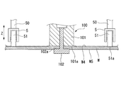
図1に示すように、本実施形態の摩擦攪拌接合装置1は、第一部材W1及び第二部材W2からなるワークWにおいて、第一部材W1と第二部材W2との接合箇所W3を摩擦攪拌接合により接合する装置である。摩擦攪拌接合装置1は、ワークWが配置されるワーク配置部2と、ワーク配置部2に配置されるワークWの表面W4側の上方に設けられた本体部3と、本体部3に設けられて、工具であるボビンツール100を保持する工具保持部4と、ワークWの表面W4上で工具保持部4を支持する支持体5と、支持体5に、ワーク配置部2に配置されるワークWに向かって、予め設定された荷重を与える荷重付与手段6とを備える。
図1に示すように、本実施形態の摩擦攪拌接合装置1は、第一部材W1及び第二部材W2からなるワークWにおいて、第一部材W1と第二部材W2との接合箇所W3を摩擦攪拌接合により接合する装置である。摩擦攪拌接合装置1は、ワークWが配置されるワーク配置部2と、ワーク配置部2に配置されるワークWの表面W4側の上方に設けられた本体部3と、本体部3に設けられて、工具であるボビンツール100を保持する工具保持部4と、ワークWの表面W4上で工具保持部4を支持する支持体5と、支持体5に、ワーク配置部2に配置されるワークWに向かって、予め設定された荷重を与える荷重付与手段6とを備える。
ここで、図2に示すように、ボビンツール100は、ワークWの表面W4側に配置され、表面W4を押圧する第一ショルダ面101aを具備する第一ショルダ部101と、ワークWの裏面W5側に配置され、裏面W5を押圧する第二ショルダ面102aを具備する第二ショルダ部102と、第一ショルダ部101の第一ショルダ面101aから突出して第二ショルダ部102が連結された軸部103とを有する。第一ショルダ部101には、第一ショルダ面101aに開口する貫通孔が形成されており、この貫通孔に軸部103が挿通されている。このため、軸部103を貫通孔に沿って進退させることによって第一ショルダ面101aに対して第二ショルダ面102aを近接及び離間させることが可能となっている。
図1に示すように、工具保持部4は、第一ショルダ部101が端面に取り付けられる略筒状の第一ショルダ取付体40と、先端に軸部103が取り付けられる第二ショルダ取付軸41と、略筒状で、第一ショルダ取付体40及び第二ショルダ取付軸41を支持する支持筒42とを有する。ここで、第一ショルダ取付体40、第二ショルダ取付軸41及び支持筒42は、同軸上に、中心軸Cをワーク対向方向となる上下方向Zに沿うように設けられている。
第一ショルダ取付体40は、略筒状に形成されている。そして、第二ショルダ取付軸41は、第一ショルダ取付体40に挿通され、第二ショルダ取付軸41の基端は第一ショルダ取付体40から突出している。第二ショルダ取付軸41には、第一ショルダ取付体40に挿通された部分において、軸方向に沿うようにしてキー41aが形成されているとともに、第一ショルダ取付体40から突出した部分には平板状のピストン41bが径方向に張り出している。一方、第一ショルダ取付体40には、第二ショルダ取付軸41のキー41aが噛合する中心軸Cに沿うキー溝40aが形成されている。そのため、第二ショルダ取付軸41は、第一ショルダ取付体40に対して中心軸C回りに回転不能であるとともに、中心軸Cに沿って進退可能に形成されている。また、第一ショルダ取付体40は、基端に径方向に張り出すフランジ40bを有する。
支持筒42は、下方に開口して第一ショルダ取付体40を中心軸C回りに回転可能に収容する取付体収容部42aと、第二ショルダ取付軸41を中心軸Cに沿って進退させるシリンダ部42bと、本体部3に支持される被支持部42cとを有する。取付体収容部42aは、第一ショルダ取付体40のフランジ40bを収容するとともに、中心軸C回りに回転可能に支持する軸受部42dを有する。また、取付体収容部42aの内周面には、第一ショルダ取付体40を中心軸C回りに回転駆動するモータ43が内蔵されている。このため、キー41a及びキー溝40aがかみ合うことによって一体に形成されている第一ショルダ取付体40と第二ショルダ取付軸41とは、モータ43の駆動により中心軸C回りに回転可能に形成される。
シリンダ部42bは、ピストン41bを支持する略筒状のピストン支持部42eと、ピストン支持部42eの先端側及び基端側の開口に設けられ、第二ショルダ取付軸41を支持する先端側支持部42f及び基端側支持部42gとを有する。ピストン41bの外周面には軸受42hが設けられている。そして、軸受42hにより、ピストン41bは、ピストン支持部42eに対して、中心軸Cに沿って進退可能かつ中心軸C回りに回転可能に支持されている。また、先端側支持部42f及び基端側支持部42gにも軸受42i、42jが設けられている。そして、軸受42i、42jにより、第二ショルダ取付軸41は、ピストン支持部42eに対して、中心軸Cに沿って進退可能かつ中心軸C回りに回転可能に支持されている。
そして、ピストン41bと、先端側支持部42f及び基端側支持部42gとの間には、作動油が供給される第一油圧室42m及び第二油圧室42nが形成されている。また、シリンダ部42bには、本体部3を貫通して外部まで接続されるとともに、それぞれ第一油圧室42mまたは第二油圧室42nまで連通する作動油供給管路42p、42qが形成されている。このため、外部に設けられた図示しない油圧制御装置から、作動油供給管路42p、42qを経由して第一油圧室42mまたは第二油圧室42nに選択的に油圧を入力することにより、第二ショルダ取付軸41を先端側または基端側へと中心軸Cに沿ってスライドさせることができる。その結果、ワーク配置部2に配置されたワークWの裏面W5に対して、中心軸Cに沿うワークに対向する方向に力を与えて第二ショルダ部102の第二ショルダ面102aによって加圧を行うことが可能である。すなわち図示しない油圧制御装置、シリンダ部42b及びピストン41bにより加圧手段44が構成されている。また、被支持部42cは、中心軸C上でシリンダ部42bから突出する軸状に形成されている。
本体部3は、加工機主軸1aに取り付けられている。本体部3は、略筒状に形成され、ワーク配置部2に配置されるワークWの表面W4側となる下方に向けて開口し工具保持部4が収容された収容部30と、収容部30に収容された工具保持部4をワークWに対して近接及び離間するように、ワークに対向する方向となる上下方向Zに進退可能に支持する本体支持部31とを有する。本体支持部31は、軸受31a、31bを有し、被支持部42cは軸受31a、31bにより中心軸Cに沿って進退可能に支持されている。
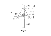
図1及び図3に示すように、支持体5は、工具保持部4の取付体収容部42aの下端面から突出する支持部材50と、支持部材50に回転可能に支持されてワークWの表面W4に当接するローラ51と、支持部材50から径方向に張り出すように設けられた張出部材52とを有する。支持体5は、工具保持部4に保持されたボビンツール100を走査する走査方向(図1において紙面奥行方向)に直交する方向Yにボビンツール100を挟むようにして両側に対をなして配置されている。そして、ローラ51は、走査方向に直交する方向Yに沿うように配された回転軸回りに回転可能に設けられている。すなわち、ローラ51は、走査方向へのボビンツール100の走査に伴ってワークWの表面W4上を走査方向に転動可能に設けられている。
ここで、図3に示すように、支持体5においてワーク配置部2に配置されたワークWの表面W4に当接する当接部、すなわちローラ51の下端51aの上下方向Zの位置は、工具保持部4に保持されたボビンツール100の第一ショルダ部101の第一ショルダ面101aと略等しい位置に設定されている。このため、平面状に形成されたワークWの表面W4上においては、ローラ51の下端51aが表面W4に当接した状態で、第一ショルダ部101の第一ショルダ面101aも表面W4に当接している。
また、図1に示すように、荷重付与手段6は、支持体5が接続されて下向きとなる自重及び保持するボビンツール100の重量分の力P1を作用させる工具保持部4と、張出部材52と本体部3の下端面との間に設けられ、中心軸Cに沿う方向に補助力P2を作用させる補助力付与部60とを有する。補助力付与部60は、工具保持部4によって作用する力P1よりも小さい所定の大きさの上向きの補助力P2を与える部材である。例えば、工具保持部4及びボビンツール100を合わせた重量による力P1が下向きに5.0kNであるのに対して、補助力P2としては上向きに4.5kNの大きさで作用させて、結果として荷重付与手段6は、下向きに0.5kNの荷重Pを作用させる。補助力付与部60は、具体的にはエアシリンダであり、上記の例では、予め4.5kN相当の空気圧が入力され、加工中にワークWの表面W4の変位等にともなって反力を受けても特に入力された空気圧の制御は行わない。
次に、この実施形態の作用について説明する。
図1に示すように、摩擦攪拌接合を行う場合には、第一ショルダ部101の第一ショルダ面101aと、第二ショルダ部102の第二ショルダ面102aとの間にワークWを配置する。また、ワークWの表面W4上に支持体5のローラ51を配置する。この状態で、補助力付与部60で所定の大きさで上向きの補助力P2が作用していることにより、支持体5には荷重Pが作用する。そして、荷重Pが支持体5からワークWに作用することによって、支持体5にはワークWから荷重P相当の反力が作用している。そして、モータ43を駆動させて工具保持部4全体を回転させるとともに、加圧手段44によって第二ショルダ部102に上向きの加圧力を作用させる。その結果、ワークWは、第二ショルダ面102aから裏面W5に加圧力を受けるとともに、第一ショルダ面101aから表面W4にも上記加圧力に相当する加圧力を同様に受ける。このため、第一ショルダ面101a及び第二ショルダ面102aと、ワークWの表面W4及び裏面W5との間には摩擦熱が生じて軟化し、軟化部を軸部103で攪拌することで、摩擦攪拌接合が行われる。
図1に示すように、摩擦攪拌接合を行う場合には、第一ショルダ部101の第一ショルダ面101aと、第二ショルダ部102の第二ショルダ面102aとの間にワークWを配置する。また、ワークWの表面W4上に支持体5のローラ51を配置する。この状態で、補助力付与部60で所定の大きさで上向きの補助力P2が作用していることにより、支持体5には荷重Pが作用する。そして、荷重Pが支持体5からワークWに作用することによって、支持体5にはワークWから荷重P相当の反力が作用している。そして、モータ43を駆動させて工具保持部4全体を回転させるとともに、加圧手段44によって第二ショルダ部102に上向きの加圧力を作用させる。その結果、ワークWは、第二ショルダ面102aから裏面W5に加圧力を受けるとともに、第一ショルダ面101aから表面W4にも上記加圧力に相当する加圧力を同様に受ける。このため、第一ショルダ面101a及び第二ショルダ面102aと、ワークWの表面W4及び裏面W5との間には摩擦熱が生じて軟化し、軟化部を軸部103で攪拌することで、摩擦攪拌接合が行われる。
ここで、支持体5は、工具保持部4に保持されたボビンツール100に対してボビンツール100の走査方向に直交する方向Yに配置されている。そのため、ボビンツール100によるワークWの摩擦攪拌に支障がないようにして、ワークWの表面W4上で支持体5によって工具保持部4を支持することができる。そして、支持体5は、上記のとおり、荷重付与手段6によって荷重Pが作用することにより、ワークWの表面W4からも荷重P相当の反力を受ける。このため、図4に示すように、ワークWの表面W4が、ワークW自体の変形、厚みの変化、ワーク配置部2におけるワークWの配置誤差等により、走査方向Xに沿って変位しても、支持体5はワークWの表面W4に沿うように追従する。
また、ボビンツール100の第一ショルダ面101aは、支持体5のローラ51の下端51aとワークに対向する方向である上下方向Zの位置が等しくなるようにして一定の相対位置関係に設定されている。すなわち、ワークに対向する方向である上下方向Zに関して、ボビンツール100の第一ショルダ面101aは、支持体5のローラ51の下端51aと位置が等しくなるように設けられている。このため、工具保持部4に保持されたボビンツール100の第一ショルダ面101aは、工具保持部4とともに、ワークWの表面W4に沿うようにしてワーク対向方向に変位し、第一ショルダ面101aとワークWの表面W4との相対位置関係を一定に保つことができる。従って、ボビンツール100の第一ショルダ面101aからワークWの表面W4に作用する加圧力を所望の力で正確に維持することがきる。
ここで、本実施形態の摩擦攪拌接合装置1では、少なくとも上記のように工具保持部4がワーク対向方向である上下方向Zに向かって進退可能に設けられ、前記工具保持部4をワークWの表面W4上で支持体5によって支持することによって加圧力を正確に維持することができる。すなわち、簡易な構成で、ワークWの表面W4に生じる誤差の影響を受けることなく、ボビンツール100によって正確に加圧して摩擦攪拌接合を行うことができる。この際、走査方向に対して支持体5とボビンツール100が同じ位置に配置されることで、ボビンツール100の位置におけるワークWの上下方向の微小な誤差をより正確に検知することができる。
また、上記のとおり、支持体5においてワークWの表面W4と当接する当接部となるローラ51の下端51aに対して、工具保持部4に保持されたボビンツール100の第一ショルダ部101の第一ショルダ面101aが上下方向Zに略等しい位置に設定されている。このため、図5に示すように、ワークWの表面W4において、第一ショルダ面101aで加圧される部位が他の部位に比較して、凹凸に形成されることがない。このため、摩擦攪拌接合後の仕上がりが良好なワークが得られる。また、上記のとおり、荷重付与手段6では、工具保持部4及びボビンツール100の重量による力P1から補助力P2を減じた荷重Pが与えられることで、ワークWに余計な負荷を与えず、かつ、支持体5がワークWの表面W4を沿うような適切な反力を発生させることができる。
なお、上記においては、支持体5においてワークWの表面W4と当接する当接部となるローラ51の下端51aに対して、工具保持部4に保持されたボビンツール100の第一ショルダ部101の第一ショルダ面101aが上下方向Zに略等しい位置に設定されているものとしたが、これに限るものではない。例えば、図6に示すように、曲面状のワークWについて摩擦攪拌接合する場合には、曲面状の表面W4に沿う面において、工具保持部4に保持されたボビンツール100の第一ショルダ部101の第一ショルダ面101aが同一面内に設けられることで、表面W4が凹凸に形成されることを防止して、摩擦攪拌接合後の仕上がりが良好なワークが得られる。
また、当接部となるローラ51の下端51aに対して、工具保持部4に保持されたボビンツール100の第一ショルダ部101の第一ショルダ面101aが、上下方向Zに関して異なる位置に配されても、ローラ51の下端51aと第一ショルダ面101aとの相対位置が所定の関係を満たすようにして設けられていれば良い。
例えば、図7に示すように、ローラ51の下端51aに対して、第一ショルダ面101aがワークWに近い位置に配されても良い。この場合には、第一ショルダ面101aがローラ51の下端51aよりもワークWに近接した距離分だけ、接合部に凹部が形成される。例えば、接合部において所定の深さで凹部を形成する必要がある場合などには、ローラ51の下端51aと第一ショルダ面101aとが、上記のような位置関係で配されても良い。また、図8に示すように、ローラ51の下端51aに対して、第一ショルダ面101aがワークWに遠い位置に配されても良い。この場合には、第一ショルダ面101aがローラ51の下端51aよりもワークWに離間した距離分だけ、接合部に凸部が形成される。例えば、接合部において所定の高さで凸部を形成する必要がある場合などには、ローラ51の下端51aと第一ショルダ面101aとが、上記のような位置関係で配されても良い。
例えば、図7に示すように、ローラ51の下端51aに対して、第一ショルダ面101aがワークWに近い位置に配されても良い。この場合には、第一ショルダ面101aがローラ51の下端51aよりもワークWに近接した距離分だけ、接合部に凹部が形成される。例えば、接合部において所定の深さで凹部を形成する必要がある場合などには、ローラ51の下端51aと第一ショルダ面101aとが、上記のような位置関係で配されても良い。また、図8に示すように、ローラ51の下端51aに対して、第一ショルダ面101aがワークWに遠い位置に配されても良い。この場合には、第一ショルダ面101aがローラ51の下端51aよりもワークWに離間した距離分だけ、接合部に凸部が形成される。例えば、接合部において所定の高さで凸部を形成する必要がある場合などには、ローラ51の下端51aと第一ショルダ面101aとが、上記のような位置関係で配されても良い。
また、上記においては、支持体5は、工具保持部4に保持されたボビンツール100を走査する走査方向に直交する方向に前記ボビンツール100を挟むようにして両側に対をなして配置されているが、これに限るものではない。例えば、本発明の実施形態に係る摩擦攪拌接合装置は、図9Aに示すように平面視して4つの支持体5を備えたり、あるいは、図9Bに示すように平面視して3つの支持体5を備えても良い。
図9Aに示すように、4つの支持体5を配置する場合、工具保持部4に保持されたボビンツール100の走査方向Xに直交する方向Yの両側に、走査方向Xに沿うように支持体5をそれぞれ2つずつ配列することで、ボビンツール100によるワークWの摩擦攪拌に支障がないようにして、ワークWの表面W4上で支持体5によって工具保持部4を支持することができる。
また、この場合には、ボビンツール100の走査方向Xを90度変更しても同様にボビンツール100による摩擦攪拌に支障がない。
また、この場合には、ボビンツール100の走査方向Xを90度変更しても同様にボビンツール100による摩擦攪拌に支障がない。
また、図9Bに示すように、3つの支持体5を配置する場合、工具保持部4に保持されたボビンツール100の走査方向Xに直交する方向Yの両側に2つの支持体5を配置し、残りの1つの支持体5を走査方向X前方側に配置しても、走査方向X前方側の支持体5は摩擦攪拌による接合前のワークWの表面W4上を走行することになるため、同様にボビンツール100による摩擦攪拌に支障がない。
また、上記実施形態では、工具保持部4をワーク配置部2に配置されたワークWの上方に配置し、工具保持部4をワーク対向方向である上下方向Zに進退可能に設けたが、これに限るものではない。例えば、ワークWを、表面W4が鉛直面を形成するように配置して、工具保持部4をワーク対向方向となる水平方向に進退可能に設けても良い。この場合には、支持体5には、工具保持部4及び工具保持部4で保持されたボビンツール100の重量が力として作用しない。このため、図1に示す構造で、支持体5に荷重を付与するためには、荷重付与手段6で発生する荷重として補助力付与部60で発生させる力そのものを利用し、ワークWに向かって対応する荷重、例えば上記実施形態における例では0.5kNの力を発生させるように空気圧を入力すればよい。また、上記実施形態では、加圧手段44を備え、第一ショルダ部101に対して第二ショルダ部102が近接及び離間可能に設けられたが、これに限るものではない。第一ショルダ部101に対する第二ショルダ部102の相対位置が変わらないように、第一ショルダ部101と第二ショルダ部102とが固定され、加圧手段44を備えない構成でも良い。
以上、本発明の実施形態について図面を参照して詳述したが、具体的な構成はこの実施形態に限られるものではなく、本発明の要旨を逸脱しない範囲の設計変更等も含まれる。
本発明の態様に係る摩擦攪拌接合装置によれば、工具保持部及び支持体により、簡易な構成でワーク表面に生じる誤差の影響を受けることなく、工具によって正確に加圧して摩擦攪拌接合を行うことができる。
1 摩擦攪拌接合装置
2 ワーク配置部
3 本体部
4 工具保持部
5 支持体
51a 下端(当接部)
6 荷重付与手段
44 加圧手段
60 補助力付与部
100 ボビンツール(工具)
101 第一ショルダ部
101a 第一ショルダ面
102 第二ショルダ部
102a 第二ショルダ面
103 軸部
W ワーク
W4 表面
W5 裏面
X 走査方向
Y 走査方向に直交する方向
Z 上下方向(ワーク対向方向)
2 ワーク配置部
3 本体部
4 工具保持部
5 支持体
51a 下端(当接部)
6 荷重付与手段
44 加圧手段
60 補助力付与部
100 ボビンツール(工具)
101 第一ショルダ部
101a 第一ショルダ面
102 第二ショルダ部
102a 第二ショルダ面
103 軸部
W ワーク
W4 表面
W5 裏面
X 走査方向
Y 走査方向に直交する方向
Z 上下方向(ワーク対向方向)
Claims (6)
- ワークの表面に当接する第一ショルダ面、及び前記ワークの裏面に当接する第二ショルダ面を有する工具を用いて、前記ワークに対して摩擦攪拌接合を行う摩擦攪拌接合装置であって、
前記ワークが配置されるワーク配置部と、
前記ワーク配置部に配置される前記ワークの前記表面側に設けられた本体部と、
前記本体部に、前記ワーク配置部に配置される前記ワークに対して近接離間する方向であるワーク対向方向に進退可能に設けられ、前記工具を保持する工具保持部と、
前記工具保持部に取り付けられた前記工具の前記第一ショルダ面と前記ワーク対向方向に所定の相対位置関係となるようにして設けられ、前記ワーク配置部に配置された前記ワークの前記表面上で、前記工具保持部を支持する支持体とを備える摩擦攪拌接合装置。 - 請求項1に記載の摩擦攪拌接合装置において、
前記支持体に、前記ワーク配置部に配置される前記ワークに向かって、予め設定された荷重を与える荷重付与手段を備える摩擦攪拌接合装置。 - 請求項2に記載の摩擦攪拌接合装置において、
前記本体部が、前記ワーク配置部に配置される前記ワークの上方に配置され、前記ワーク対向方向として上下方向に前記工具保持部を進退可能に支持しており、
前記荷重付与手段は、前記本体部に取り付けられ、前記工具保持部に対して、前記工具保持部及び前記工具保持部に取り付けられた前記工具の重量よりも小さい所定の大きさの上向きの補助力を与える補助力付与部を有し、前記荷重として、前記工具保持部と前記工具保持部に取り付けられた前記工具の重量から前記補助力を減じた荷重を与える摩擦攪拌接合装置。 - 請求項1から請求項3のいずれか一項に記載の摩擦攪拌接合装置において、
前記支持体は、前記工具保持部に保持された前記工具に対して、前記工具の走査方向に直交する方向に配置されている摩擦攪拌接合装置。 - 請求項1から請求項4のいずれか一項に記載の摩擦攪拌接合装置において、
前記支持体は、前記ワークの前記表面に当接する当接部が、前記工具保持部に保持された前記工具の前記第一ショルダ面と、前記ワークの前記表面に沿う同一面内となるように設けられている摩擦攪拌接合装置。 - 請求項1から請求項5のいずれか一項に記載の摩擦攪拌接合装置において、
前記工具が、前記第一ショルダ面を具備する第一ショルダ部と、前記第一ショルダ面から進退可能に突出する軸部と、前記軸部の先端に取り付けられ前記第二ショルダ面を具備する第二ショルダ部とを有し、
前記工具保持部は、前記軸部に前記ワーク対向方向に力を与えて、前記第二ショルダ面によって前記ワークの前記裏面を加圧させる加圧手段を有する摩擦攪拌接合装置。
Priority Applications (3)
| Application Number | Priority Date | Filing Date | Title |
|---|---|---|---|
| CN201180037181.XA CN103068514B (zh) | 2011-02-18 | 2011-05-27 | 摩擦搅拌接合装置 |
| US13/812,642 US9776276B2 (en) | 2011-02-18 | 2011-05-27 | Friction stir welding device |
| EP11858672.6A EP2676762B1 (en) | 2011-02-18 | 2011-05-27 | Friction stir welding device |
Applications Claiming Priority (2)
| Application Number | Priority Date | Filing Date | Title |
|---|---|---|---|
| JP2011-033503 | 2011-02-18 | ||
| JP2011033503A JP5374528B2 (ja) | 2011-02-18 | 2011-02-18 | 摩擦攪拌接合装置及び摩擦攪拌接合方法 |
Publications (1)
| Publication Number | Publication Date |
|---|---|
| WO2012111181A1 true WO2012111181A1 (ja) | 2012-08-23 |
Family
ID=46672137
Family Applications (1)
| Application Number | Title | Priority Date | Filing Date |
|---|---|---|---|
| PCT/JP2011/062213 WO2012111181A1 (ja) | 2011-02-18 | 2011-05-27 | 摩擦攪拌接合装置 |
Country Status (5)
| Country | Link |
|---|---|
| US (1) | US9776276B2 (ja) |
| EP (1) | EP2676762B1 (ja) |
| JP (1) | JP5374528B2 (ja) |
| CN (1) | CN103068514B (ja) |
| WO (1) | WO2012111181A1 (ja) |
Cited By (2)
| Publication number | Priority date | Publication date | Assignee | Title |
|---|---|---|---|---|
| CN104718045A (zh) * | 2012-12-19 | 2015-06-17 | 三菱重工业株式会社 | 接合材料的制造方法及接合用夹具 |
| CN114589393A (zh) * | 2020-12-07 | 2022-06-07 | 财团法人金属工业研究发展中心 | 摩擦搅拌焊接压持治具系统 |
Families Citing this family (11)
| Publication number | Priority date | Publication date | Assignee | Title |
|---|---|---|---|---|
| AT509066B1 (de) * | 2010-08-11 | 2011-06-15 | Stirzone Og | Vorrichtung zum reibrührschweissen |
| JP5536007B2 (ja) * | 2011-10-19 | 2014-07-02 | 三菱重工業株式会社 | 摩擦撹拌接合装置及び摩擦撹拌接合方法 |
| JP6084887B2 (ja) * | 2013-04-16 | 2017-02-22 | 川崎重工業株式会社 | 摩擦撹拌接合装置および摩擦撹拌接合方法 |
| JP6226184B2 (ja) * | 2013-11-07 | 2017-11-08 | 三菱重工業株式会社 | 摩擦撹拌接合方法 |
| DE102014101627A1 (de) * | 2014-02-10 | 2015-08-13 | Ms Spaichingen Gmbh | Gestell für eine Maschine |
| DE112015001811T5 (de) * | 2014-04-16 | 2017-01-19 | Fanuc Corp. | Rührreibschweiß-Vorrichtung |
| EP3069812B1 (en) * | 2015-03-18 | 2017-11-29 | Helmholtz-Zentrum Geesthacht Zentrum für Material- und Küstenforschung GmbH | Apparatus for friction stir welding with a shoulder comprising first and second through holes |
| CN108140584B (zh) * | 2015-09-29 | 2021-06-01 | 东芝三菱电机产业系统株式会社 | 超声波振动接合装置 |
| KR101833294B1 (ko) * | 2016-09-19 | 2018-03-02 | 주식회사 현성오토텍 | 마찰교반접합용 회전접합부재 |
| DE102021126767A1 (de) | 2021-10-15 | 2023-04-20 | Universität Kassel, Körperschaft des öffentlichen Rechts | Rührreibschweißvorrichtung |
| CN117359082A (zh) * | 2023-09-14 | 2024-01-09 | 北京赛福斯特技术有限公司 | 一种填充式搅拌摩擦增材制造装置及增材制造方法 |
Citations (9)
| Publication number | Priority date | Publication date | Assignee | Title |
|---|---|---|---|---|
| JPH10305372A (ja) * | 1997-05-07 | 1998-11-17 | Amada Co Ltd | 溶接装置 |
| JP2001287054A (ja) * | 2000-04-07 | 2001-10-16 | Hitachi Ltd | 摩擦撹拌接合方法 |
| JP2003062679A (ja) * | 2001-08-29 | 2003-03-05 | Nippon Light Metal Co Ltd | 摩擦攪拌接合ツール |
| JP2004130326A (ja) | 2002-10-08 | 2004-04-30 | Mitsubishi Heavy Ind Ltd | 摩擦攪拌接合装置とその接合方法 |
| JP2004188488A (ja) * | 2002-12-13 | 2004-07-08 | Mitsubishi Heavy Ind Ltd | 摩擦攪拌による接合構体の製造装置 |
| JP2004216435A (ja) * | 2003-01-16 | 2004-08-05 | Mitsubishi Heavy Ind Ltd | 摩擦攪拌接合装置とその接合方法 |
| JP2005007454A (ja) * | 2003-06-20 | 2005-01-13 | Mitsubishi Heavy Ind Ltd | ロケットタンクシリンダの製造方法及びその製造装置 |
| JP2006088208A (ja) * | 2004-09-27 | 2006-04-06 | Mitsubishi Heavy Ind Ltd | 摩擦撹拌接合方法及び装置 |
| JP2010214401A (ja) | 2009-03-16 | 2010-09-30 | Kawasaki Heavy Ind Ltd | 摩擦撹拌接合装置及び方法 |
Family Cites Families (9)
| Publication number | Priority date | Publication date | Assignee | Title |
|---|---|---|---|---|
| JPS594230B2 (ja) | 1974-10-03 | 1984-01-28 | 三菱重工業株式会社 | クミタテヨウセツソウチ |
| DK1105246T3 (da) * | 1998-07-09 | 2011-08-01 | Mts System Corp | Svejsehoved |
| US6302315B1 (en) * | 2000-05-01 | 2001-10-16 | General Tool Company | Friction stir welding machine and method |
| US8397974B2 (en) * | 2005-09-26 | 2013-03-19 | Aeroprobe Corporation | Self-reacting friction stir welding tool with the ability to add filler material |
| JP4790584B2 (ja) | 2006-12-14 | 2011-10-12 | 日本車輌製造株式会社 | 摩擦攪拌接合装置及び摩擦攪拌接合方法 |
| CN101622093B (zh) * | 2007-03-30 | 2013-03-13 | 川崎重工业株式会社 | 吸附垫、摩擦搅拌接合装置、摩擦搅拌接合系统 |
| US8079276B2 (en) * | 2008-04-15 | 2011-12-20 | Spirit Aerosystems, Inc. | Dynamic calibration assembly for a friction stir welding machine |
| US8052028B2 (en) | 2008-06-16 | 2011-11-08 | GM Global Technology Operations LLC | Device for use with a friction stir spot welding (FSSW) apparatus |
| CN101947691B (zh) | 2010-09-29 | 2012-05-30 | 哈尔滨工业大学 | 上、下轴肩直径不等的自持式搅拌摩擦焊方法及其搅拌头 |
-
2011
- 2011-02-18 JP JP2011033503A patent/JP5374528B2/ja active Active
- 2011-05-27 CN CN201180037181.XA patent/CN103068514B/zh active Active
- 2011-05-27 US US13/812,642 patent/US9776276B2/en active Active
- 2011-05-27 WO PCT/JP2011/062213 patent/WO2012111181A1/ja active Application Filing
- 2011-05-27 EP EP11858672.6A patent/EP2676762B1/en active Active
Patent Citations (9)
| Publication number | Priority date | Publication date | Assignee | Title |
|---|---|---|---|---|
| JPH10305372A (ja) * | 1997-05-07 | 1998-11-17 | Amada Co Ltd | 溶接装置 |
| JP2001287054A (ja) * | 2000-04-07 | 2001-10-16 | Hitachi Ltd | 摩擦撹拌接合方法 |
| JP2003062679A (ja) * | 2001-08-29 | 2003-03-05 | Nippon Light Metal Co Ltd | 摩擦攪拌接合ツール |
| JP2004130326A (ja) | 2002-10-08 | 2004-04-30 | Mitsubishi Heavy Ind Ltd | 摩擦攪拌接合装置とその接合方法 |
| JP2004188488A (ja) * | 2002-12-13 | 2004-07-08 | Mitsubishi Heavy Ind Ltd | 摩擦攪拌による接合構体の製造装置 |
| JP2004216435A (ja) * | 2003-01-16 | 2004-08-05 | Mitsubishi Heavy Ind Ltd | 摩擦攪拌接合装置とその接合方法 |
| JP2005007454A (ja) * | 2003-06-20 | 2005-01-13 | Mitsubishi Heavy Ind Ltd | ロケットタンクシリンダの製造方法及びその製造装置 |
| JP2006088208A (ja) * | 2004-09-27 | 2006-04-06 | Mitsubishi Heavy Ind Ltd | 摩擦撹拌接合方法及び装置 |
| JP2010214401A (ja) | 2009-03-16 | 2010-09-30 | Kawasaki Heavy Ind Ltd | 摩擦撹拌接合装置及び方法 |
Cited By (3)
| Publication number | Priority date | Publication date | Assignee | Title |
|---|---|---|---|---|
| CN104718045A (zh) * | 2012-12-19 | 2015-06-17 | 三菱重工业株式会社 | 接合材料的制造方法及接合用夹具 |
| US9393640B2 (en) | 2012-12-19 | 2016-07-19 | Mitsubishi Heavy Industries, Ltd. | Welded material manufacturing method and welding jig |
| CN114589393A (zh) * | 2020-12-07 | 2022-06-07 | 财团法人金属工业研究发展中心 | 摩擦搅拌焊接压持治具系统 |
Also Published As
| Publication number | Publication date |
|---|---|
| EP2676762A4 (en) | 2016-12-28 |
| EP2676762A1 (en) | 2013-12-25 |
| JP2012170966A (ja) | 2012-09-10 |
| US9776276B2 (en) | 2017-10-03 |
| EP2676762B1 (en) | 2019-03-13 |
| CN103068514B (zh) | 2016-02-17 |
| US20130119115A1 (en) | 2013-05-16 |
| CN103068514A (zh) | 2013-04-24 |
| JP5374528B2 (ja) | 2013-12-25 |
Similar Documents
| Publication | Publication Date | Title |
|---|---|---|
| WO2012111181A1 (ja) | 摩擦攪拌接合装置 | |
| JP4751477B1 (ja) | 工作機械におけるワーククランプ装置 | |
| JP5725868B2 (ja) | 端部加工装置 | |
| US9481049B2 (en) | Combined machining method and combined machining device | |
| US20110229280A1 (en) | Deep hole processing device | |
| JP2013184261A (ja) | ワーク加工用治具、ワーク自動加工装置、ワーク加工方法、ワーク加工プログラム及び記録媒体 | |
| JP2013086137A (ja) | 摩擦撹拌接合装置 | |
| KR101799218B1 (ko) | 마찰 교반 접합 방법 | |
| JP2015178160A (ja) | 工作機械の工具に対してワークを回転可能に支持する治具及び加工システム | |
| KR20140026662A (ko) | 용접장치 및 방법 | |
| KR20100070438A (ko) | 푸싱지그 및 이를 구비한 피가공물 고정장치 | |
| KR20130069202A (ko) | 레이저 용접용 지그 장치 | |
| JP6405994B2 (ja) | ロールヘミング加工装置 | |
| CA2561053C (en) | Friction stir welding tool with counterbearing for mounting on a handling device | |
| JP2016005854A (ja) | 回転対称体のクランプ治具を搭載した工作機械 | |
| CN108290260B (zh) | 工件把持装置 | |
| JP2004167511A (ja) | 摩擦撹拌接合装置および摩擦撹拌接合方法 | |
| CN113710388B (zh) | 复合加工机 | |
| WO2018016226A1 (ja) | 切削工具支持装置及び工作機械 | |
| CN108290262B (zh) | 工件移送装置 | |
| JP2007237245A (ja) | 摩擦攪拌接合装置および摩擦攪拌接合方法 | |
| JP6540794B2 (ja) | 摩擦撹拌接合装置 | |
| JP2008272898A (ja) | 工作機械における工具のアンクランプ方法 | |
| JP2008302440A (ja) | ワーク取付具及び工作機械 | |
| JP3488946B2 (ja) | ブランク材の突き合わせ位置決め装置 |
Legal Events
| Date | Code | Title | Description |
|---|---|---|---|
| WWE | Wipo information: entry into national phase |
Ref document number: 201180037181.X Country of ref document: CN |
|
| 121 | Ep: the epo has been informed by wipo that ep was designated in this application |
Ref document number: 11858672 Country of ref document: EP Kind code of ref document: A1 |
|
| WWE | Wipo information: entry into national phase |
Ref document number: 13812642 Country of ref document: US |
|
| WWE | Wipo information: entry into national phase |
Ref document number: 2011858672 Country of ref document: EP |
|
| NENP | Non-entry into the national phase |
Ref country code: DE |