WO2012108245A1 - ポリカーボネート樹脂ペレットの製造方法 - Google Patents
ポリカーボネート樹脂ペレットの製造方法 Download PDFInfo
- Publication number
- WO2012108245A1 WO2012108245A1 PCT/JP2012/051052 JP2012051052W WO2012108245A1 WO 2012108245 A1 WO2012108245 A1 WO 2012108245A1 JP 2012051052 W JP2012051052 W JP 2012051052W WO 2012108245 A1 WO2012108245 A1 WO 2012108245A1
- Authority
- WO
- WIPO (PCT)
- Prior art keywords
- polycarbonate resin
- water
- pellets
- resin
- extruder
- Prior art date
- Legal status (The legal status is an assumption and is not a legal conclusion. Google has not performed a legal analysis and makes no representation as to the accuracy of the status listed.)
- Ceased
Links
Images


Classifications
-
- C—CHEMISTRY; METALLURGY
- C08—ORGANIC MACROMOLECULAR COMPOUNDS; THEIR PREPARATION OR CHEMICAL WORKING-UP; COMPOSITIONS BASED THEREON
- C08G—MACROMOLECULAR COMPOUNDS OBTAINED OTHERWISE THAN BY REACTIONS ONLY INVOLVING UNSATURATED CARBON-TO-CARBON BONDS
- C08G64/00—Macromolecular compounds obtained by reactions forming a carbonic ester link in the main chain of the macromolecule
- C08G64/40—Post-polymerisation treatment
- C08G64/406—Purifying; Drying
-
- B—PERFORMING OPERATIONS; TRANSPORTING
- B29—WORKING OF PLASTICS; WORKING OF SUBSTANCES IN A PLASTIC STATE IN GENERAL
- B29B—PREPARATION OR PRETREATMENT OF THE MATERIAL TO BE SHAPED; MAKING GRANULES OR PREFORMS; RECOVERY OF PLASTICS OR OTHER CONSTITUENTS OF WASTE MATERIAL CONTAINING PLASTICS
- B29B11/00—Making preforms
- B29B11/06—Making preforms by moulding the material
- B29B11/10—Extrusion moulding
-
- B—PERFORMING OPERATIONS; TRANSPORTING
- B29—WORKING OF PLASTICS; WORKING OF SUBSTANCES IN A PLASTIC STATE IN GENERAL
- B29B—PREPARATION OR PRETREATMENT OF THE MATERIAL TO BE SHAPED; MAKING GRANULES OR PREFORMS; RECOVERY OF PLASTICS OR OTHER CONSTITUENTS OF WASTE MATERIAL CONTAINING PLASTICS
- B29B11/00—Making preforms
- B29B11/14—Making preforms characterised by structure or composition
-
- B—PERFORMING OPERATIONS; TRANSPORTING
- B29—WORKING OF PLASTICS; WORKING OF SUBSTANCES IN A PLASTIC STATE IN GENERAL
- B29B—PREPARATION OR PRETREATMENT OF THE MATERIAL TO BE SHAPED; MAKING GRANULES OR PREFORMS; RECOVERY OF PLASTICS OR OTHER CONSTITUENTS OF WASTE MATERIAL CONTAINING PLASTICS
- B29B7/00—Mixing; Kneading
- B29B7/30—Mixing; Kneading continuous, with mechanical mixing or kneading devices
- B29B7/34—Mixing; Kneading continuous, with mechanical mixing or kneading devices with movable mixing or kneading devices
- B29B7/38—Mixing; Kneading continuous, with mechanical mixing or kneading devices with movable mixing or kneading devices rotary
- B29B7/40—Mixing; Kneading continuous, with mechanical mixing or kneading devices with movable mixing or kneading devices rotary with single shaft
- B29B7/42—Mixing; Kneading continuous, with mechanical mixing or kneading devices with movable mixing or kneading devices rotary with single shaft with screw or helix
- B29B7/421—Mixing; Kneading continuous, with mechanical mixing or kneading devices with movable mixing or kneading devices rotary with single shaft with screw or helix with screw and additionally other mixing elements on the same shaft, e.g. paddles, discs, bearings, rotor blades of the Banbury type
-
- B—PERFORMING OPERATIONS; TRANSPORTING
- B29—WORKING OF PLASTICS; WORKING OF SUBSTANCES IN A PLASTIC STATE IN GENERAL
- B29B—PREPARATION OR PRETREATMENT OF THE MATERIAL TO BE SHAPED; MAKING GRANULES OR PREFORMS; RECOVERY OF PLASTICS OR OTHER CONSTITUENTS OF WASTE MATERIAL CONTAINING PLASTICS
- B29B7/00—Mixing; Kneading
- B29B7/30—Mixing; Kneading continuous, with mechanical mixing or kneading devices
- B29B7/34—Mixing; Kneading continuous, with mechanical mixing or kneading devices with movable mixing or kneading devices
- B29B7/38—Mixing; Kneading continuous, with mechanical mixing or kneading devices with movable mixing or kneading devices rotary
- B29B7/46—Mixing; Kneading continuous, with mechanical mixing or kneading devices with movable mixing or kneading devices rotary with more than one shaft
- B29B7/48—Mixing; Kneading continuous, with mechanical mixing or kneading devices with movable mixing or kneading devices rotary with more than one shaft with intermeshing devices, e.g. screws
- B29B7/482—Mixing; Kneading continuous, with mechanical mixing or kneading devices with movable mixing or kneading devices rotary with more than one shaft with intermeshing devices, e.g. screws provided with screw parts in addition to other mixing parts, e.g. paddles, gears, discs
- B29B7/483—Mixing; Kneading continuous, with mechanical mixing or kneading devices with movable mixing or kneading devices rotary with more than one shaft with intermeshing devices, e.g. screws provided with screw parts in addition to other mixing parts, e.g. paddles, gears, discs the other mixing parts being discs perpendicular to the screw axis
-
- B—PERFORMING OPERATIONS; TRANSPORTING
- B29—WORKING OF PLASTICS; WORKING OF SUBSTANCES IN A PLASTIC STATE IN GENERAL
- B29B—PREPARATION OR PRETREATMENT OF THE MATERIAL TO BE SHAPED; MAKING GRANULES OR PREFORMS; RECOVERY OF PLASTICS OR OTHER CONSTITUENTS OF WASTE MATERIAL CONTAINING PLASTICS
- B29B7/00—Mixing; Kneading
- B29B7/74—Mixing; Kneading using other mixers or combinations of mixers, e.g. of dissimilar mixers ; Plant
- B29B7/7461—Combinations of dissimilar mixers
-
- B—PERFORMING OPERATIONS; TRANSPORTING
- B29—WORKING OF PLASTICS; WORKING OF SUBSTANCES IN A PLASTIC STATE IN GENERAL
- B29B—PREPARATION OR PRETREATMENT OF THE MATERIAL TO BE SHAPED; MAKING GRANULES OR PREFORMS; RECOVERY OF PLASTICS OR OTHER CONSTITUENTS OF WASTE MATERIAL CONTAINING PLASTICS
- B29B7/00—Mixing; Kneading
- B29B7/74—Mixing; Kneading using other mixers or combinations of mixers, e.g. of dissimilar mixers ; Plant
- B29B7/7476—Systems, i.e. flow charts or diagrams; Plants
- B29B7/7485—Systems, i.e. flow charts or diagrams; Plants with consecutive mixers, e.g. with premixing some of the components
-
- B—PERFORMING OPERATIONS; TRANSPORTING
- B29—WORKING OF PLASTICS; WORKING OF SUBSTANCES IN A PLASTIC STATE IN GENERAL
- B29B—PREPARATION OR PRETREATMENT OF THE MATERIAL TO BE SHAPED; MAKING GRANULES OR PREFORMS; RECOVERY OF PLASTICS OR OTHER CONSTITUENTS OF WASTE MATERIAL CONTAINING PLASTICS
- B29B7/00—Mixing; Kneading
- B29B7/80—Component parts, details or accessories; Auxiliary operations
- B29B7/84—Venting or degassing ; Removing liquids, e.g. by evaporating components
- B29B7/845—Venting, degassing or removing evaporated components in devices with rotary stirrers
-
- B—PERFORMING OPERATIONS; TRANSPORTING
- B29—WORKING OF PLASTICS; WORKING OF SUBSTANCES IN A PLASTIC STATE IN GENERAL
- B29B—PREPARATION OR PRETREATMENT OF THE MATERIAL TO BE SHAPED; MAKING GRANULES OR PREFORMS; RECOVERY OF PLASTICS OR OTHER CONSTITUENTS OF WASTE MATERIAL CONTAINING PLASTICS
- B29B7/00—Mixing; Kneading
- B29B7/80—Component parts, details or accessories; Auxiliary operations
- B29B7/86—Component parts, details or accessories; Auxiliary operations for working at sub- or superatmospheric pressure
-
- B—PERFORMING OPERATIONS; TRANSPORTING
- B29—WORKING OF PLASTICS; WORKING OF SUBSTANCES IN A PLASTIC STATE IN GENERAL
- B29B—PREPARATION OR PRETREATMENT OF THE MATERIAL TO BE SHAPED; MAKING GRANULES OR PREFORMS; RECOVERY OF PLASTICS OR OTHER CONSTITUENTS OF WASTE MATERIAL CONTAINING PLASTICS
- B29B7/00—Mixing; Kneading
- B29B7/80—Component parts, details or accessories; Auxiliary operations
- B29B7/88—Adding charges, i.e. additives
- B29B7/94—Liquid charges
-
- B—PERFORMING OPERATIONS; TRANSPORTING
- B29—WORKING OF PLASTICS; WORKING OF SUBSTANCES IN A PLASTIC STATE IN GENERAL
- B29B—PREPARATION OR PRETREATMENT OF THE MATERIAL TO BE SHAPED; MAKING GRANULES OR PREFORMS; RECOVERY OF PLASTICS OR OTHER CONSTITUENTS OF WASTE MATERIAL CONTAINING PLASTICS
- B29B9/00—Making granules
- B29B9/02—Making granules by dividing preformed material
- B29B9/06—Making granules by dividing preformed material in the form of filamentary material, e.g. combined with extrusion
-
- B—PERFORMING OPERATIONS; TRANSPORTING
- B29—WORKING OF PLASTICS; WORKING OF SUBSTANCES IN A PLASTIC STATE IN GENERAL
- B29B—PREPARATION OR PRETREATMENT OF THE MATERIAL TO BE SHAPED; MAKING GRANULES OR PREFORMS; RECOVERY OF PLASTICS OR OTHER CONSTITUENTS OF WASTE MATERIAL CONTAINING PLASTICS
- B29B9/00—Making granules
- B29B9/12—Making granules characterised by structure or composition
-
- B—PERFORMING OPERATIONS; TRANSPORTING
- B29—WORKING OF PLASTICS; WORKING OF SUBSTANCES IN A PLASTIC STATE IN GENERAL
- B29C—SHAPING OR JOINING OF PLASTICS; SHAPING OF MATERIAL IN A PLASTIC STATE, NOT OTHERWISE PROVIDED FOR; AFTER-TREATMENT OF THE SHAPED PRODUCTS, e.g. REPAIRING
- B29C49/00—Blow-moulding, i.e. blowing a preform or parison to a desired shape within a mould; Apparatus therefor
- B29C49/071—Preforms or parisons characterised by their configuration, e.g. geometry, dimensions or physical properties
-
- C—CHEMISTRY; METALLURGY
- C08—ORGANIC MACROMOLECULAR COMPOUNDS; THEIR PREPARATION OR CHEMICAL WORKING-UP; COMPOSITIONS BASED THEREON
- C08L—COMPOSITIONS OF MACROMOLECULAR COMPOUNDS
- C08L69/00—Compositions of polycarbonates; Compositions of derivatives of polycarbonates
-
- B—PERFORMING OPERATIONS; TRANSPORTING
- B29—WORKING OF PLASTICS; WORKING OF SUBSTANCES IN A PLASTIC STATE IN GENERAL
- B29B—PREPARATION OR PRETREATMENT OF THE MATERIAL TO BE SHAPED; MAKING GRANULES OR PREFORMS; RECOVERY OF PLASTICS OR OTHER CONSTITUENTS OF WASTE MATERIAL CONTAINING PLASTICS
- B29B9/00—Making granules
- B29B9/16—Auxiliary treatment of granules
-
- B—PERFORMING OPERATIONS; TRANSPORTING
- B29—WORKING OF PLASTICS; WORKING OF SUBSTANCES IN A PLASTIC STATE IN GENERAL
- B29C—SHAPING OR JOINING OF PLASTICS; SHAPING OF MATERIAL IN A PLASTIC STATE, NOT OTHERWISE PROVIDED FOR; AFTER-TREATMENT OF THE SHAPED PRODUCTS, e.g. REPAIRING
- B29C2791/00—Shaping characteristics in general
- B29C2791/004—Shaping under special conditions
- B29C2791/005—Using a particular environment, e.g. sterile fluids other than air
-
- B—PERFORMING OPERATIONS; TRANSPORTING
- B29—WORKING OF PLASTICS; WORKING OF SUBSTANCES IN A PLASTIC STATE IN GENERAL
- B29C—SHAPING OR JOINING OF PLASTICS; SHAPING OF MATERIAL IN A PLASTIC STATE, NOT OTHERWISE PROVIDED FOR; AFTER-TREATMENT OF THE SHAPED PRODUCTS, e.g. REPAIRING
- B29C2793/00—Shaping techniques involving a cutting or machining operation
- B29C2793/0027—Cutting off
-
- B—PERFORMING OPERATIONS; TRANSPORTING
- B29—WORKING OF PLASTICS; WORKING OF SUBSTANCES IN A PLASTIC STATE IN GENERAL
- B29C—SHAPING OR JOINING OF PLASTICS; SHAPING OF MATERIAL IN A PLASTIC STATE, NOT OTHERWISE PROVIDED FOR; AFTER-TREATMENT OF THE SHAPED PRODUCTS, e.g. REPAIRING
- B29C2949/00—Indexing scheme relating to blow-moulding
- B29C2949/07—Preforms or parisons characterised by their configuration
- B29C2949/0715—Preforms or parisons characterised by their configuration the preform having one end closed
-
- B—PERFORMING OPERATIONS; TRANSPORTING
- B29—WORKING OF PLASTICS; WORKING OF SUBSTANCES IN A PLASTIC STATE IN GENERAL
- B29C—SHAPING OR JOINING OF PLASTICS; SHAPING OF MATERIAL IN A PLASTIC STATE, NOT OTHERWISE PROVIDED FOR; AFTER-TREATMENT OF THE SHAPED PRODUCTS, e.g. REPAIRING
- B29C48/00—Extrusion moulding, i.e. expressing the moulding material through a die or nozzle which imparts the desired form; Apparatus therefor
- B29C48/001—Combinations of extrusion moulding with other shaping operations
- B29C48/0022—Combinations of extrusion moulding with other shaping operations combined with cutting
-
- B—PERFORMING OPERATIONS; TRANSPORTING
- B29—WORKING OF PLASTICS; WORKING OF SUBSTANCES IN A PLASTIC STATE IN GENERAL
- B29C—SHAPING OR JOINING OF PLASTICS; SHAPING OF MATERIAL IN A PLASTIC STATE, NOT OTHERWISE PROVIDED FOR; AFTER-TREATMENT OF THE SHAPED PRODUCTS, e.g. REPAIRING
- B29C48/00—Extrusion moulding, i.e. expressing the moulding material through a die or nozzle which imparts the desired form; Apparatus therefor
- B29C48/03—Extrusion moulding, i.e. expressing the moulding material through a die or nozzle which imparts the desired form; Apparatus therefor characterised by the shape of the extruded material at extrusion
- B29C48/04—Particle-shaped
-
- B—PERFORMING OPERATIONS; TRANSPORTING
- B29—WORKING OF PLASTICS; WORKING OF SUBSTANCES IN A PLASTIC STATE IN GENERAL
- B29C—SHAPING OR JOINING OF PLASTICS; SHAPING OF MATERIAL IN A PLASTIC STATE, NOT OTHERWISE PROVIDED FOR; AFTER-TREATMENT OF THE SHAPED PRODUCTS, e.g. REPAIRING
- B29C48/00—Extrusion moulding, i.e. expressing the moulding material through a die or nozzle which imparts the desired form; Apparatus therefor
- B29C48/14—Extrusion moulding, i.e. expressing the moulding material through a die or nozzle which imparts the desired form; Apparatus therefor characterised by the particular extruding conditions, e.g. in a modified atmosphere or by using vibration
- B29C48/143—Extrusion moulding, i.e. expressing the moulding material through a die or nozzle which imparts the desired form; Apparatus therefor characterised by the particular extruding conditions, e.g. in a modified atmosphere or by using vibration at a location before or in the feed unit, e.g. influencing the material in the hopper
-
- B—PERFORMING OPERATIONS; TRANSPORTING
- B29—WORKING OF PLASTICS; WORKING OF SUBSTANCES IN A PLASTIC STATE IN GENERAL
- B29C—SHAPING OR JOINING OF PLASTICS; SHAPING OF MATERIAL IN A PLASTIC STATE, NOT OTHERWISE PROVIDED FOR; AFTER-TREATMENT OF THE SHAPED PRODUCTS, e.g. REPAIRING
- B29C48/00—Extrusion moulding, i.e. expressing the moulding material through a die or nozzle which imparts the desired form; Apparatus therefor
- B29C48/25—Component parts, details or accessories; Auxiliary operations
- B29C48/36—Means for plasticising or homogenising the moulding material or forcing it through the nozzle or die
- B29C48/50—Details of extruders
- B29C48/505—Screws
- B29C48/625—Screws characterised by the ratio of the threaded length of the screw to its outside diameter [L/D ratio]
-
- B—PERFORMING OPERATIONS; TRANSPORTING
- B29—WORKING OF PLASTICS; WORKING OF SUBSTANCES IN A PLASTIC STATE IN GENERAL
- B29C—SHAPING OR JOINING OF PLASTICS; SHAPING OF MATERIAL IN A PLASTIC STATE, NOT OTHERWISE PROVIDED FOR; AFTER-TREATMENT OF THE SHAPED PRODUCTS, e.g. REPAIRING
- B29C48/00—Extrusion moulding, i.e. expressing the moulding material through a die or nozzle which imparts the desired form; Apparatus therefor
- B29C48/25—Component parts, details or accessories; Auxiliary operations
- B29C48/36—Means for plasticising or homogenising the moulding material or forcing it through the nozzle or die
- B29C48/50—Details of extruders
- B29C48/76—Venting, drying means; Degassing means
- B29C48/762—Vapour stripping
-
- B—PERFORMING OPERATIONS; TRANSPORTING
- B29—WORKING OF PLASTICS; WORKING OF SUBSTANCES IN A PLASTIC STATE IN GENERAL
- B29K—INDEXING SCHEME ASSOCIATED WITH SUBCLASSES B29B, B29C OR B29D, RELATING TO MOULDING MATERIALS OR TO MATERIALS FOR MOULDS, REINFORCEMENTS, FILLERS OR PREFORMED PARTS, e.g. INSERTS
- B29K2069/00—Use of PC, i.e. polycarbonates or derivatives thereof, as moulding material
-
- B—PERFORMING OPERATIONS; TRANSPORTING
- B29—WORKING OF PLASTICS; WORKING OF SUBSTANCES IN A PLASTIC STATE IN GENERAL
- B29K—INDEXING SCHEME ASSOCIATED WITH SUBCLASSES B29B, B29C OR B29D, RELATING TO MOULDING MATERIALS OR TO MATERIALS FOR MOULDS, REINFORCEMENTS, FILLERS OR PREFORMED PARTS, e.g. INSERTS
- B29K2469/00—Use of PC, i.e. polycarbonates or derivatives thereof as filler
Definitions
- the present invention relates to a method for producing polycarbonate resin pellets. More specifically, the content of impurities such as chlorine compounds is extremely small, the resin is hardly deteriorated, yellowing does not occur, the pellet appearance is good, and resin additives are free.
- the present invention relates to a method for producing polycarbonate resin pellets that can be used in the above.
- Polycarbonate resin is a general-purpose engineering plastic that excels in transparency, impact resistance, heat resistance, dimensional stability, etc., and its excellent characteristics make it an excellent choice in a wide range of fields such as electrical / electronic / OA equipment parts, machine parts, and vehicle parts. in use.
- Various electrical and electronic equipment parts such as a silicon wafer, a disk substrate, a data storage hard disk, an optical storage disk, an IC chip, and a high-performance substrate glass for LCD are used as parts in the electrical and electronic equipment. In the manufacture of electrical and electronic equipment, these parts must be transported and transported in order to be used in an assembly line, and a transport case for this purpose is used.
- Various thermoplastic resins have been used.
- Polycarbonate resins especially those that react aromatic dihydroxy compounds with phosgene in methylene chloride (ie dichloromethane) solvents, by so-called interfacial polymerization, contain methylene chloride and other chlorine compounds, albeit slightly. These chlorine compounds are decomposed when melted to generate acidic substances. By removing these contaminants from the polycarbonate resin material, it is expected to improve the reliability of the transport case using the same.
- methylene chloride ie dichloromethane
- Patent Document 1 a method of removing impurities by adding water at the time of melt extrusion (for example, see Patent Document 1) is known.
- Patent Document 2 foamed water is added.
- the degree of cleanliness is not sufficient for transport cases that require a high level, and a polycarbonate resin molding material having a higher level of cleanliness is more efficient.
- a method of manufacturing well has been desired.
- the object of the present invention is that the content of impurities such as chlorine compounds is extremely small, the resin is hardly deteriorated, yellowing does not occur, the pellet appearance is good, and the resin additive is free. It is providing the method of manufacturing the polycarbonate resin pellet which can be used.
- the present inventors use a polycarbonate resin having a specific specific surface area and particle size, respectively, specific inert gas treatment process, water injection process, vacuum suction process, respectively. It was found that by combining the cooling step, the cutting step, and the aging step, polycarbonate resin pellets having an extremely low level of impurity content that could not be achieved until now can be obtained, and the present invention has been completed.
- a method for producing a polycarbonate resin pellet having a reduced methylene chloride content from a polycarbonate resin containing a small amount of methylene chloride 1) As a polycarbonate containing a small amount of methylene chloride, a polycarbonate resin in the form of a granular material having a specific surface area of 0.008 m 2 / g or more and 50% by mass or more having a particle diameter of 200 to 2,000 ⁇ m is used.
- An inert gas treatment step in which a polycarbonate resin in the form of granules is dropped and moved by 50 cm or more in an inert gas atmosphere having an oxygen concentration of 3% by volume or less, 3)
- the inert gas-treated polycarbonate resin in the form of granules is supplied to a vent-type extruder, and in the kneading zone, water having an electric conductivity of 30 ⁇ S / cm or less is added to 0.1 parts by mass of 100 parts by mass of the polycarbonate resin.
- a method for producing a polycarbonate resin pellet is provided.
- a method for producing polycarbonate resin pellets characterized in that in the first invention, a drying step of drying the moisture-containing pellets obtained through the aging step is further performed. Provided.
- the powdery polycarbonate resin when the powdery polycarbonate resin is treated with the inert gas, the powder fluid is supplied in a falling state, and the inert gas is supplied from below.
- a method for producing a polycarbonate resin pellet which is supplied so as to be countercurrent to the granular material.
- a method for producing polycarbonate resin pellets according to the first aspect wherein the oxygen concentration in the barrel of the vented extruder is 3% by volume or less.
- the kneading zone for injecting water is a resin-filled region, and the resin pressure is in the range of 0.5 to 10 MPa.
- a method for producing polycarbonate resin pellets is provided.
- the length of the region where the resin filling rate in the decompression section of the extruder is 5 to 30% by volume is 8.0D (D is an extrusion rate).
- D is an extrusion rate.
- a method for producing a polycarbonate resin pellet is provided, which is equal to or greater than the cylinder inner diameter of the machine.
- the method for producing polycarbonate resin pellets according to the first aspect wherein the temperature of water for cooling the strand is 30 to 90 ° C.
- an electric and electronic equipment component carrying case characterized by using the polycarbonate resin pellet of the eighth invention.
- the content of impurities such as chlorine compounds is extremely small, the resin is hardly deteriorated and yellowing does not occur, the pellet appearance is good, and particularly the electric and electronic A polycarbonate resin pellet that can be used without using a resin additive, which is suitable for a case for conveying equipment parts, can be produced.
- the present invention is a method for producing polycarbonate resin pellets having a reduced methylene chloride content from a polycarbonate resin containing a small amount of methylene chloride, 1) As a polycarbonate containing a small amount of methylene chloride, a polycarbonate resin in the form of a granular material having a specific surface area of 0.008 m 2 / g or more and 50% by mass or more having a particle diameter of 200 to 2,000 ⁇ m is used.
- An inert gas treatment step in which a polycarbonate resin in the form of granules is dropped and moved by 50 cm or more in an inert gas atmosphere having an oxygen concentration of 3% by mass or less, 3)
- the inert gas-treated polycarbonate resin in the form of granules is supplied to a vent-type extruder, and in the kneading zone, water having an electric conductivity of 30 ⁇ S / cm or less is added to 0.1 parts by mass of 100 parts by mass of the polycarbonate resin.
- polycarbonate resin (A) used in the present invention examples include aromatic polycarbonate resins, aliphatic polycarbonate resins, and aromatic-aliphatic polycarbonate resins, preferably aromatic polycarbonate resins.
- a thermoplastic aromatic polycarbonate polymer or copolymer obtained by reacting an aromatic dihydroxy compound with phosgene or a diester of carbonic acid is used.
- Aromatic dihydroxy compounds include 2,2-bis (4-hydroxyphenyl) propane (bisphenol A), tetramethylbisphenol A, ⁇ , ⁇ '-bis (4-hydroxyphenyl) -p-diisopropylbenzene, hydroquinone, resorcinol 4,4′-dihydroxydiphenyl and the like. Further, as a part of the dihydroxy compound, when the above-mentioned aromatic dihydroxy compound is combined with one or more tetraalkylphosphonium sulfonates, or a polymer or oligomer containing both terminal phenolic OH groups having a siloxane structure, A highly flame-retardant polycarbonate resin can be obtained.
- Preferred examples of the polycarbonate resin used in the present invention include 2,2-bis (4-hydroxyphenyl) propane as a dihydroxy compound, or 2,2-bis (4-hydroxyphenyl) propane and another aromatic dihydroxy compound. The polycarbonate resin used together is mentioned.
- the production method of the polycarbonate resin is not particularly limited, but it is usually produced by an interfacial polymerization method (phosgene method) or a melt method (transesterification method).
- the polymerization reaction is usually carried out in the presence of an organic solvent inert to the reaction and an aqueous alkaline solution, and the pH is usually kept at 9 or higher.
- an antioxidant for preventing oxidation of the aromatic dihydroxy compound, and after reacting with phosgene, a polymerization catalyst such as a tertiary amine or a quaternary ammonium salt is added, and interfacial polymerization is carried out to obtain a polymer.
- a sulfonate resin is obtained.
- the addition of the molecular weight regulator is not particularly limited as long as it is from the time of phosgenation to the start of the polymerization reaction.
- the reaction temperature is, for example, 0 to 40 ° C.
- the reaction time is, for example, several minutes (for example, 10 minutes) to several hours (for example, 6 hours).
- examples of the organic solvent inert to the reaction include chlorinated hydrocarbons such as dichloromethane, 1,2-dichloroethane, chloroform, monochlorobenzene and dichlorobenzene.
- examples of the alkali compound used in the alkaline aqueous solution include hydroxides of alkali metals such as sodium hydroxide and potassium hydroxide.
- the molecular weight regulator examples include compounds having a monovalent phenolic hydroxyl group, such as m-methylphenol, p-methylphenol, m-propylphenol, p-propylphenol, p-tert. Preferred examples include -butylphenol and p-long chain alkyl-substituted phenol.
- the amount of the molecular weight regulator used is preferably 50 to 0.5 mol, more preferably 30 to 1 mol, per 100 mol of the aromatic dihydroxy compound.
- Polymerization catalysts include tertiary amines such as trimethylamine, triethylamine, tributylamine, tripropylamine, trihexylamine, pyridine, and quaternary ammonium salts such as trimethylbenzylammonium chloride, tetramethylammonium chloride, and triethylbenzylammonium chloride. Etc.
- the polymerization reaction in this production method is, for example, a transesterification reaction between a carbonic acid diester and an aromatic dihydroxy compound.
- the carbonic acid diester include dialkyl carbonate compounds such as dimethyl carbonate, diethyl carbonate and di-tert-butyl carbonate, and substituted diphenyl carbonates such as diphenyl carbonate and ditolyl carbonate.
- An example is a bonate.
- the carbonic acid diester is preferably diphenyl carbonate or substituted diphenyl carbonate, more preferably diphenyl carbonate.
- the mixing ratio of the carbonic acid diester and the aromatic dihydroxy compound and the degree of pressure reduction during the transesterification reaction are adjusted to obtain an aromatic polycarbonate resin having the desired molecular weight and terminal hydroxyl group content adjusted. be able to.
- an equimolar amount or more of a carbonic acid diester is used with respect to 1 mol of an aromatic dihydroxy compound, among which 1.001 to 1.3 mol, particularly 1.01 to 1.2 mol is used. preferable.
- a terminal terminator separately at the time of reaction
- examples of the terminal terminator in this case include monohydric phenols, monovalent carboxylic acids, and carbonic acid diesters. It is done.
- the polycarbonate resin used in the present invention may be produced by any of the above interfacial polymerization method and melt polymerization method.
- methylene chloride derived from a polymerization solvent, a catalyst, a catalyst deactivator, a reaction by-product and the like, and chloroformate which is an unreacted residue are included in the polycarbonate resin produced by the interfacial polymerization method. It contains not a few chlorine compounds such as group-containing compounds and is preferable for the purpose of the present invention. Therefore, the method of the present invention is suitable for using a polycarbonate resin produced by an interfacial polymerization method.
- the molecular weight of the polycarbonate resin is a viscosity average molecular weight converted from the solution viscosity measured at a temperature of 25 ° C. using methylene chloride as a solvent, and is usually in the range of 10,000 to 50,000, and 15,000 to 30,000. The range is preferably in the range of 17,500 to 27,000. If the viscosity average molecular weight is less than 10,000, the mechanical strength is inferior, and if it exceeds 50,000, the moldability is inferior.
- the polycarbonate resin used in the present invention is intended to contain a very small amount of methylene chloride.
- the small amount means that it contains 200 ppm or less of a chlorine-containing compound in terms of the amount of chlorine atoms.
- the polycarbonate resin obtained by the interfacial polymerization method usually contains 20 ppm or more of a chlorine-containing compound when taken out from the polymerization system.
- the normal content of methylene chloride in the raw material polycarbonate resin is 10 to 100 ppm.
- the polycarbonate resin is used as having a granular shape. Specifically, 50% by mass or more of the polycarbonate resin has a particle size distribution measured by a method in accordance with JIS K0069 (screening test method) of 200 to 2,000 ⁇ m, preferably 300 to 2,000 ⁇ m, more preferably Is a granular material in the range of 400 to 2,000 ⁇ m. If a resin having a particle size of less than 200 ⁇ m or more than 2,000 ⁇ m is contained in an amount exceeding 50% by mass, components having a particle size of less than 200 ⁇ m are likely to rise, making it difficult to quantitatively supply from the feeder to the extruder. Become. Moreover, about the component which has a particle size exceeding 2,000 micrometers, the effect of the process by the following inert gas becomes scarce.
- the polycarbonate resin further has a specific surface area of 0.008 m 2 / g or more, preferably 0.01 m 2 / g or more, more preferably 0.012 m 2 / g or more.
- the specific surface area of the polycarbonate resin is a value determined by the BET multipoint method.
- the shape of the granular material in the present invention is not particularly limited as long as it has a fine particle size distribution as described above, so-called powder, granular material such as fine pellets, granular material, flakes, etc. It refers to the shape.
- Polycarbonate resin should not be added as much as possible of additives that may become pollutants when used in applications that require a low amount of semiconductor pollutants such as chlorine, such as containers for semiconductor substrates.
- additives such as chlorine, such as containers for semiconductor substrates.
- Additives such as impact modifiers, antistatic agents, plasticizers, compatibilizers can be included.
- additives may be used alone or in combination of two or more. Among these, it is particularly preferable to use a heat stabilizer and an antioxidant.
- a phosphorus compound is mentioned preferably. Any known phosphorous compound can be used. Specific examples include phosphorus oxo acids such as phosphoric acid, phosphonic acid, phosphorous acid, phosphinic acid, polyphosphoric acid, acidic pyrophosphoric acid metal salts such as acidic sodium pyrophosphate, acidic potassium pyrophosphate, acidic calcium pyrophosphate, and phosphoric acid. Examples include Group 1 or Group 10 metal phosphates such as potassium, sodium phosphate, cesium phosphate, and zinc phosphate, organic phosphate compounds, organic phosphite compounds, and organic phosphonite compounds.
- triphenyl phosphite tris (monononylphenyl) phosphite, tris (monononyl / dinonyl phenyl) phosphite, tris (2,4-di-tert-butylphenyl) phosphite, monooctyl diphenyl phosphite, Dioctyl monophenyl phosphite, monodecyl diphenyl phosphite, didecyl monophenyl phosphite, tridecyl phosphite, trilauryl phosphite, tristearyl phosphite, 2,2-methylenebis (4,6-di-tert-butylphenyl) ) Organic phosphites such as octyl phosphite are preferred.
- the content of the heat stabilizer is usually 0.001 part by mass or more, preferably 0.01 part by mass or more, more preferably 0.03 part by mass or more, based on 100 parts by mass of the polycarbonate resin. It is not more than part by mass, preferably not more than 0.7 part by mass, more preferably not more than 0.5 part by mass. If the amount of the heat stabilizer is too small, the heat stabilization effect may be insufficient. If the amount of the heat stabilizer is too large, the effect may reach a peak and may not be economical.
- antioxidant for example, a hindered phenol-based antioxidant is preferably mentioned. Specific examples thereof include pentaerythritol tetrakis [3- (3,5-di-tert-butyl-4-hydroxyphenyl) propionate], octadecyl-3- (3,5-di-tert-butyl-4-hydroxyphenyl).
- pentaerythritol tetrakis [3- (3,5-di-tert-butyl-4-hydroxyphenyl) propionate], octadecyl-3- (3,5-di-tert-butyl-4-hydroxyphenyl) propionate preferable.
- a phenolic antioxidant specifically, for example, “Irganox 1010” (registered trademark, the same applies below) manufactured by Ciba Specialty Chemicals Inc.
- Ilganox 1076 “ ADK STAB AO-50 ”,“ Adeka Stub AO-60 ”manufactured by ADEKA Corporation, and the like.
- 1 type may contain antioxidant and 2 or more types may contain it by arbitrary combinations and a ratio.
- the content of the antioxidant is usually 0.001 part by mass or more, preferably 0.01 part by mass or more, and usually 1 part by mass or less, preferably 0.5 part by mass with respect to 100 parts by mass of the polycarbonate resin. Or less.
- the content of the antioxidant is less than or equal to the lower limit of the range, the effect as an antioxidant may be insufficient, and when the content of the antioxidant exceeds the upper limit of the range, There is a possibility that the effect reaches its peak and is not economical.
- the polycarbonate resin in the present invention not only a virgin raw material but also a polycarbonate resin regenerated from a used product, that is, a so-called material recycled polycarbonate resin may be used. It is also possible to use a pulverized product obtained from the above or a granular material obtained by melting them.
- the regenerated polycarbonate resin is used by mixing with a non-recycled granule-shaped polycarbonate resin, and the mixing amount is preferably 80% by mass or less, more preferably 50% by mass of the total polycarbonate resin component. % Or less, in particular 30% by mass.
- the polycarbonate resin in the form of a granular material is first treated with an inert gas.
- the treatment with the inert gas is performed with the polycarbonate resin in a specific shape and in a specific state.
- a polycarbonate resin in the form of a granular material having a specific surface area of 0.008 m 2 / g or more and a particle size of 50 to 50% by mass of 200 to 2,000 ⁇ m as a polycarbonate containing a small amount of methylene chloride is prepared.
- such a granular-shaped polycarbonate resin is dropped and moved in an inert gas atmosphere having an oxygen concentration of 3% by volume or less by 50 cm or more.
- the reason why the polycarbonate resin has such a special shape is to increase the area (surface) in contact with the inert gas, and to efficiently remove oxygen remaining on the surface of the granular material by the inert gas, Further, the reason why the particles are moved down is to increase the processing efficiency by moving the powder particles in the inert gas.
- an inert gas is flowed from below into a tubular member in which a granular polycarbonate resin is placed vertically, and the granular polycarbonate resin is supplied from above using a quantitative feeder, etc. What is necessary is just to move by making it fall.
- a simple method is a method in which a polycarbonate resin in the form of a granular material is supplied and dropped from above a hopper having a height of 50 cm or more (a hopper of an extruder) and an inert gas is supplied from the base of the hopper. Can be mentioned.
- FIG. 1 is a diagram showing a configuration example of a feeder-hopper-extruder applicable to the present invention.
- the bottom of the hopper chute is connected to the supply port of the extruder, and the polycarbonate resin is sequentially supplied to the extruder via the hopper chute, and melted and kneaded in the extruder to become a resin molding material such as pellets.
- the mixing can be blended at an arbitrary stage before being fed into the extruder.
- a tumbler a Henschel mixer, and a blender
- they may be fed into a hopper chute via a feeder and supplied to an extruder as necessary.
- the extruder a single screw extruder, a twin screw extruder or the like can be used.
- you may supply to a hopper chute
- the atmosphere inside the hopper chute for supplying the material to the extruder is replaced with an inert gas.
- the inert gas means not only a rare gas but also a gas inert to the polycarbonate resin powder to be used.
- the inert gas for example, nitrogen gas, carbon dioxide gas, rare gas or the like is used, and nitrogen gas is particularly preferably used.
- the inert gas supplied to the hopper chute to replace the atmosphere in the hopper chute is preferably in a dry state and a purity of 99% by volume or more.
- the inert gas can be supplied from the vicinity of the supply port of the hopper chute extruder or from the upper part of the hopper chute, but is supplied from the vicinity of the supply port (lowermost part). It is preferable to do. This is because it is desirable to maintain a high inert gas concentration in the atmosphere below the hopper chute when replacing the air in the resin with the inert gas in the atmosphere while dropping the polycarbonate resin.
- the hopper chute preferably has an airtightness enough to discharge the substituted air to the outside while maintaining a high inert gas concentration in the internal atmosphere.
- the inert gas is continuously supplied at a flow rate that maintains the low oxygen concentration in the internal atmosphere while discharging the air substituted in the hopper chute.
- the specific flow rate can be appropriately determined according to the size and airtightness of the hopper chute.
- the powdered fluid when treating the polycarbonate resin in the form of a granular material with an inert gas, the powdered fluid is supplied in a falling state so that the inert gas is counterflowed to the granular material from below. It is preferable to supply to.
- the oxygen concentration in the atmosphere inside the hopper chute is 3% by volume or less, preferably 1% by volume or less, more preferably 0.5% by volume or less, and most preferably 0.1% by volume or less. It is preferable to supply gas.
- the oxygen concentration can be measured, for example, in the lower part of the hopper chute and in the vicinity of the supply port of the extruder. If the oxygen concentration exceeds 3% by volume, the effect of suppressing yellowing due to oxidative degradation or the like and the effect of removing chlorine compounds cannot be sufficiently obtained.
- the inert gas can be supplied not only into the hopper chute but also into the barrel of the extruder.
- the polycarbonate resin is supplied to the extruder after passing through an inert gas atmosphere in a dispersed state. Specifically, the inside of the hopper chute where the internal atmosphere is replaced with an inert gas is dropped and supplied to the extruder.
- the polycarbonate resin in the form of granules so as to fall in the hopper chute in a dispersed state.
- the “dispersed state” means a state in which the surface of each resin particle can sufficiently come into contact with the atmosphere, but a special supply method is not required, and the granular shape of the present invention is not necessary.
- the polycarbonate resin can be dropped in a dispersed state by continuously (or intermittently) supplying the polycarbonate resin from the upper part of the hopper using a screw-type quantitative supply device or the like. It is not preferable in the case of falling in a dense state or a lump rather than in a dispersed state.
- the polycarbonate resin in the form of a granular material falls in an inert gas atmosphere at a vertical distance of 50 cm or more, preferably 80 cm or more. After that, feed it to reach the feed port of the extruder.
- a polycarbonate resin is supplied to a hopper chute using a feeder, as shown in FIG. 2 (a)
- the height of the feeder outlet and the material supply port of the extruder (hopper chute bottom)
- the vertical distance h is set to 50 cm or more.
- the vertical distance h between the height of the feeder outlet and the apex of the deposited material is set to 50 cm or more.
- FIG. when using a twin-screw extruder as an extruder, when performing a starvation supply (starvation feed) called a starvation material supply method in which materials are supplied in small amounts into the cylinder of the extruder, FIG. It will be in the state of a). Moreover, when the starvation supply is not performed, such as when a single screw extruder is used, the state shown in FIG. Therefore, the type of the extruder, the presence / absence of the starvation feed, the extrusion speed, and the supply amount of the material are determined so that the polycarbonate resin in the form of granular material falls 50 cm or more in the hopper chute. It has been confirmed that stable extrusion can be performed by using a starvation feed.
- starvation feed starvation feed
- the polycarbonate resin in the form of a granular material may be dropped by 50 cm or more in an inert gas atmosphere at a substantial vertical distance, and the dropping process is not particularly limited. It is not necessary to drop more than 50 cm at a time. Also, for example, as shown in FIG. 2 (c), the tip of the polycarbonate resin in the form of a granule falls on the inner surface of the hopper chute so as to fall stepwise (zigzag) and reach the material supply port of the extruder.
- One or more plate-shaped members (baffle plates) inclined toward the surface may be provided.
- the total distance (zigzag distance) dropped in a plurality of steps may be 50 cm or more.
- the fall is not limited to free fall, and may be any downward movement. Therefore, the distance dropped while sliding on the baffle plate is also included in the fall distance.
- the replacement of the air contained in the resin with the inert gas progresses when the time in contact with the atmosphere (inert gas) is longer in the dispersed state than in the state in which the particles are accumulated.
- the air drops into the hopper chute more slowly than in the case of dropping 50 cm or more in one free fall, so that the replacement efficiency of air and inert gas is increased.
- the polycarbonate resin targeted by the present invention has a granular shape with a small particle size, the air resistance is larger than the shape like a pellet and the speed of free fall is small. Is replaced with an inert gas.
- the polycarbonate resin in the form of a granular material that has been treated with an inert gas in this manner is supplied to a vent-type extruder.
- water is injected and added, and the polycarbonate resin is melt-extruded while degassing with a vent.
- water to be injected water having an electric conductivity of 30 ⁇ S / cm or less is used.
- the electrical conductivity exceeds 30 ⁇ S / cm, the cleanliness of the obtained polycarbonate resin pellets deteriorates.
- the mechanism that affects the cleanliness of polycarbonate resin pellets from which electrical conductivity is obtained is not yet clear, but it is presumed to be due to the interaction of ionic components with polycarbonate and impurities.
- the electrical conductivity of water is preferably 20 ⁇ S / cm or less, more preferably 10 ⁇ S / cm or less, further preferably 5 ⁇ S / cm or less, particularly preferably 3 ⁇ S / cm or less, and most preferably 1 ⁇ S / cm or less.
- the electrical conductivity is measured at a measurement temperature of 25 ° C. using a conductivity meter.
- the amount of water injected is 0.1 to 2 parts by mass with respect to 100 parts by mass of the polycarbonate resin. inject. If the amount of water injected is less than 0.1 parts by mass, the effect of adding water will not be exhibited, and the chlorine compound in the polycarbonate resin will be less than 3 ppm in terms of chlorine atoms, and more than 2 parts by mass. If it becomes, deaeration in a vent part will become inadequate and it will come to have a bad influence of hydrolysis etc. with respect to polycarbonate resin. In addition, a large amount of generated steam causes resin vent-up.
- the preferable amount of water injected is 0.15 to 1.8 parts by weight, more preferably 0.2 to 1.5 parts by weight, and further 0.3 to 1.2 parts by weight with respect to 100 parts by weight of the polycarbonate resin. In particular, it is 0.4 to 1.0 part by mass.
- the extruder with a vent used in the present invention may be a single screw extruder or a twin screw extruder, but a twin screw extruder is preferred. Further, the number of vents may be one or two or more, and preferably 2 to 6 locations. There may be two or more places where water is injected and added.
- the L / D of the screw of the extruder is preferably 10 to 80, more preferably 15 to 70, and more preferably 20 to 60. If it is too short, deaeration tends to be insufficient, and if it is too long, the color tone tends to deteriorate.
- the kneading zone for injecting water is a place where the molten polycarbonate resin is fully filled (preferably in the full area.
- the full area is the amount of resin relative to the space capacity per pitch of the screw in the kneading zone (true When expressed in terms of the ratio (capacity by density) (filling rate; unit: volume%), it means 95% by volume or more, preferably 98% by volume or more, more preferably 99% by volume or more, and particularly 100% by volume. It is preferable that
- the resin pressure in the water injection part (cylinder pressure in the kneading part) is preferably 0.5 to 10 MPa, more preferably 1 to 8 MPa, and more preferably 2 to 7 MPa.
- the pressure of the polycarbonate resin is increased and water is dispersed in the molten polycarbonate resin. If the resin pressure is too small, the effect of removing methylene chloride is small, and if it is too large, the resin deteriorates and the color tone tends to deteriorate.
- the screw configuration of the extruder is as follows: 1) a water injection point is provided immediately after the location where the seal ring is provided on the upstream side, or 2) a progressive kneading element is provided from the upstream side, followed by reverse feed kneading. It is recommended that the element be installed and then watered.
- the seal ring is a ring shape fitted to a screw, and closes 70 to 90% of the flow path to retain the resin flow, thereby increasing the resin pressure.
- a water injection point is provided on the downstream side immediately after this.
- a forward kneading element for feeding the resin to the downstream side when rotated is provided, and then a reverse kneading element for returning the resin to the upstream side when rotated is provided.
- the resin pressure is increased and water is injected after this.
- the oxygen concentration in the barrel (cylinder) of the vent type extruder is preferably 3% by volume or less. It becomes easy to prevent yellowing of the polycarbonate resin pellet obtained by setting it as 3 volume% or less.
- an inert gas may be injected from the hopper side (screw base) of the extruder. If it is difficult to directly measure the oxygen concentration in the barrel, a significant difference cannot be considered, so the oxygen concentration at the bottom of the hopper is substituted.
- the vent port provided near the tip of the extruder that is, near the tip of the extruder, is sucked in a reduced pressure state, so that methylene chloride and the like are melted together with water from the molten resin.
- Remove volatile components by suction By this suction, the non-filled region between the filled region at the screw tip after the kneaded portion filled with the resin is in a reduced pressure state (depressurized portion).
- the vent port is connected to a vacuum exhaust device (not shown), and decompressed exhaust is performed.
- the polycarbonate resin in the high-temperature and high-pressure state in which water is dispersed in the previous process is vaporized and expanded by rapid decompression at the vent part, and foams to expand the surface area of the polycarbonate resin. From the surface together with water, methylene chloride, etc. Volatile components are volatilized.
- the degree of vacuum at the vent port is ⁇ 0.05 MPa or less, more preferably ⁇ 0.07 MPa or less, and still more preferably ⁇ 0.09 MPa or less.
- the moisture concentration in the polycarbonate resin in the molten state cannot be directly measured with the molten resin in the extruder, so that the moisture concentration in the pellets described later is substituted. It is considered that there is little difference between the moisture concentration in the molten resin in the die and the moisture concentration in the pellet.
- the length of the decompression section is preferably 8.0D (D is the cylinder inner diameter of the extruder) or more in the screw direction, and more preferably 12D or more.
- the resin filling rate of the decompression part is preferably 5 to 30% by volume. This is because it is preferable to sufficiently reduce the filling rate of the molten polycarbonate resin and sufficiently perform deaeration.
- a more preferable resin filling rate is 8 to 25% by volume, and more preferably 10 to 20% by volume. When the resin filling rate is lower than 5% by volume, the amount of resin that can be processed decreases, and thus productivity decreases.
- the moisture concentration in the polycarbonate resin after extrusion is adjusted to 10 to 200 ppm.
- the reason for setting the moisture concentration in such a range is to remove methylene chloride and the like well without deteriorating the polycarbonate resin. When kneading and venting so that the moisture concentration is less than 10 ppm, the polycarbonate resin tends to deteriorate. If the amount exceeds 200 ppm, methylene chloride and the like also remain. Moreover, by setting it as the water content of such a range, the effect that a strand cut is stabilized by the plasticization effect of water can also be expected.
- the water concentration in the polycarbonate resin is preferably 15 to 150 ppm, more preferably 20 to 100 ppm.
- the moisture content in the polycarbonate immediately after extrusion is measured by placing only the surface adsorbed water by placing it in a vacuum dryer within 3 minutes and drying at room temperature for about 5 minutes after the strand is cooled and cut. It can be measured with a trace moisture measuring device.
- the polycarbonate resin is extruded as a strand from the die of the extruder, introduced into water, and cooled.
- the diameter of the die of the discharge nozzle is usually about 2 to 5 mm, although it depends on the extrusion pressure and the desired pellet size.
- the temperature of the polycarbonate resin immediately after being extruded is usually about 300 ° C.
- the strand is taken up by a take-up roller and cooled in such a manner that it is transported through the water stored in the cooling tank. In order to reduce the deterioration of the resin, it is better that the time from when the strand is pushed out of the die until entering the water is shorter. Normally, it is better to enter the water within 1 second after being pushed out of the die.
- the present invention at this time, it is introduced into water having an electric conductivity of 30 ⁇ S / cm or less. If the electrical conductivity of the water used exceeds 30 ⁇ S / cm, the cleanliness of the resulting polycarbonate resin pellets deteriorates.
- the electrical conductivity of water is preferably 20 ⁇ S / cm or less, more preferably 10 ⁇ S / cm or less, further preferably 5 ⁇ S / cm or less, particularly preferably 3 ⁇ S / cm or less, and most preferably 1 ⁇ S / cm or less.
- the water stored in the cooling tank deteriorates with time, and the electrical conductivity increases.
- the electrical conductivity is kept within a predetermined range (30 ⁇ S / cm or less) by constantly supplying cooling water and causing the water to overflow from the tank. Can be kept in.
- the temperature of the water tank varies depending on the position, and the temperature is usually highest when the strand enters the water tank, and the temperature of the water tank decreases as it cools. If the temperature of the water tank is too low, the strand is supercooled, and if the temperature of the water tank is high, the temperature of the strand is too high.
- a preferable range of the temperature of the water tank is 30 ° C. to 90 ° C., and a more preferable range is 40 ° C. to 70 ° C.
- the strand cooled in this way is sent to a pelletizer by a take-up roller, and is cut into pellets. Cutting is performed when the strand temperature is in the range of 70-130 ° C, preferably 75-125 ° C. Then, a water-containing pellet containing 10 to 200 ppm, preferably 15 to 150 ppm of moisture is obtained. Since the obtained water-containing pellet has not undergone an excessive shearing history by the extruder, it becomes a pellet having a high cleanliness without causing a significant molecular weight reduction or hydrolysis. If the strand temperature falls below 70 ° C, the strand becomes too hard, and breakage and chipping are likely to occur when cutting with a pelletizer.
- the strand temperature at this time may be measured with a non-contact type thermometer, but it is substituted by simply inserting a thermometer into the pellets in the bag or container containing the pellets cut by the cutter. Just do it.
- the pellets cut by the cutter are put in a paper bag, a paper drum can, a metal container or the like and brought into contact with moist air to be aged. If the pellet cut by the cutter is left as it is, static electricity is charged, and it is easy to adsorb dust and floor dust in the air. In order to reduce this static electricity, there is a method of positively neutralizing with a static eliminator (for example, ionizer SJ-M02: manufactured by Keyence Corporation), but simply put the pellet in a metal container etc. and let it come into contact with moist air. Can be reduced.
- a static eliminator for example, ionizer SJ-M02: manufactured by Keyence Corporation
- the aging step can obtain a pellet with less dust and dust adhesion.
- the humid air is preferably 40% or more, more preferably 50%, particularly preferably 60% or more of the relative humidity.
- pellets cut with a cutter are stored in polyethylene bags with a relatively high water vapor transmission rate before being polluted with dust, etc., and placed in a room on a daily or monthly basis for aging. Is the method.
- the temperature and humidity in this long-time treatment may be room temperature and normal humidity, but of course, it is preferable to control the moisture content by adjusting the date and time in a temperature-controlled and humidity-controlled environment.
- the moisture content after aging is preferably 1300 ppm or less. If the water content is exceeded, the resin is easily hydrolyzed when a desired molded product is molded using the water-containing pellets, causing a problem that the strength of the molded product is lowered. Moreover, even if it is dried before the molding of the pellets, it takes time to dry and the productivity is lowered.
- a preferable moisture content is 1000 ppm or less. More preferably, it is 700 ppm or less.
- the target charge amount is preferably 10 kV or less, more preferably 8 kV or less.
- a drying step of drying the water-containing pellets obtained through the aging step is further performed.
- the purpose of the water-containing step is to eliminate static electricity and suppress the adsorption of dust.
- the water content in the pellet is adjusted again before molding the molded product.
- the moisture-containing pellets are dried and the moisture content is adjusted to 50 to 200 ppm.
- the drying treatment is performed in a hot air dryer at a temperature of about 100 to 130 ° C., preferably in the range of 105 to 125 ° C., usually in the range of 2 to 10 hours, preferably 3 to 7 hours.
- the polycarbonate resin pellets (pellets after drying treatment) obtained by the present invention are molded into an arbitrary shape and used as a molded body.
- the manufacturing method of a molded object is not specifically limited, The molding method generally employ
- injection molding method, ultra-high speed injection molding method, injection compression molding method, two-color molding method, hollow molding method such as gas assist, molding method using heat insulating mold, rapid heating mold were used.
- Molding method foam molding (including supercritical fluid), insert molding, IMC (in-mold coating molding) molding method, extrusion molding method, sheet molding method, thermoforming method, rotational molding method, laminate molding method, press molding method, etc. Is mentioned.
- a molding method using a hot runner method can also be used.
- the polycarbonate resin pellet of the present invention has a very low content of impurities such as chlorine compounds, is less deteriorated in resin, does not cause yellowing, and can be used free of resin additives. It can be widely used in electrical and electronic equipment and the like that require a high degree of cleanness of the molded body, and is particularly useful for a case for conveying parts of electrical and electronic equipment.
- the transfer case includes various magazines, trays, boxes, containers, and the like.
- the electric / electronic device components are not particularly limited, but include components for various electric / electronic devices such as silicon wafers, hard disks, various disk substrates, IC chips, and high-functional substrate glass for LCD.
- PC-1 Manufacture of polycarbonate resin (PC-1))
- PC-1 Manufacture of polycarbonate resin (PC-1)
- a solution of bisphenol-A dissolved in a caustic soda solution in which hydrosulfite is dissolved at 35 ° C. and then cooled to 25 ° C. and methylene chloride cooled to 5 ° C. are continuously added to a stainless steel pipe having an inner diameter of 6 mm. And the mixture was passed through a homomixer and emulsified to prepare an emulsion.
- the feed rates to the pipe are bisphenol-A 16.31 kg / hr, caustic soda 5.93 kg / hr, water 101.1 kg / hr, hydrosulfite 0.018 kg / hr, and methylene chloride 68.0 kg / hr.
- the produced emulsion was passed through a pipe reactor having an inner diameter of 6 mm and a polytetrafluoroethylene resin pipe reactor having an inner diameter of 6 mm and a length of 34 m.
- liquefied phosgene cooled to 0 ° C. was supplied to the pipe reactor at 7.5 kg / hr to cause reaction to produce oligomers.
- the flow rate of the pipe reactor is 1.7 m / sec.
- the temperature rose to 60 ° C., but was 35 ° C. at the outlet due to external cooling.
- the reaction mixture was allowed to stand and separate into an aqueous phase and an oil phase.
- the resulting oligomer had a chloroformate concentration of 0.47 N, an OH terminal concentration of 0.23 N, and an oligomer concentration of 27.7%.
- 40 kg was fractionated from the obtained oil phase and charged into a reaction vessel with an internal volume of 200 liters equipped with a Faudler blade.
- a catalyst of 25 kg of methylene chloride, 5.75 kg of 25% aqueous sodium hydroxide solution, 41 kg of water and 0.87 g of pyridine hydrochloride (0.020 mol% with respect to bisphenol-A) was added to this, and 360 rpm at 10 ° C. for 60 minutes in a nitrogen atmosphere.
- the polymerization reaction was carried out with stirring to produce a polycarbonate resin with all OH terminals (OH terminal group concentration: 60 ⁇ eq / g).
- the organic phase was added with 20 kg of 0.1N aqueous sodium hydroxide solution, stirred for 15 minutes, and then allowed to stand to separate into an aqueous phase and an organic phase three times.
- 20 kg of 0.1 N hydrochloric acid was added to the organic phase after alkali washing, and the mixture was stirred for 15 minutes and then allowed to stand to separate the aqueous phase and the organic phase.
- the organic phase was added with 20 kg of pure water, stirred for 15 minutes, and then left to stand and separated into an aqueous phase and an oil phase three times. As a result, chlorine ions were not detected in the aqueous phase. Therefore, the washing operation was stopped.
- the methylene chloride was removed by evaporation from the organic phase with a kneader, and the resulting powder was dried to obtain a polycarbonate resin (PC-1).
- PC-2 PC-1 is pulverized at 650 rpm with a granulator “HB189” manufactured by Furukawa Industrial Machinery Co., Ltd. (Furukawa Industrial Systems Co.).
- PC-3 Granules obtained by extruding the PC-1 with TEX30 ⁇ manufactured by Japan Steel Works, Inc. at a discharge rate of 50 kg / hr and a screw rotation speed of 200 rpm, cooling in a water bath, and strand cutting.
- the specific surface area of the polycarbonate resin was determined by subjecting the sample to 110 ° C. under vacuum (about 1.3 Pa or less) for 3 hours under reduced pressure, and then to Quantachrome.
- An adsorption isotherm (adsorbed gas: krypton) was measured at a liquid nitrogen temperature using a powder measuring instrument Autosorb (AUTOSORB) 1MP manufactured by Instruments, and the obtained isotherm was obtained by the BET multipoint method.
- the particle size was determined as follows.
- the particle size distribution of 1 mm or more using a mesh of 1 mm or more, and the particle size distribution of 1 mm or less are determined by a particle size distribution (wet method) using a laser diffraction scattering type particle size distribution measuring device (LMS-2000e manufactured by Seishin Enterprise Co).
- LMS-2000e laser diffraction scattering type particle size distribution measuring device
- the volume average particle system was determined.
- Example 1 A mesh configuration same direction twin screw vent type extruder (TEX30 ⁇ manufactured by Nippon Steel Works, cylinder length 52.5D (D is cylinder inner diameter)) was used, and screw configuration A shown in FIG. 3 was used. As shown in FIG. 3, for the sake of explanation, C1 to C15 are divided into the same length from the hopper side of the extruder toward the die.
- the screw configuration A is configured as follows for each zone shown in FIG. a) Melting zone: A forward feed screw having a length of 31.5D and a lead of 1.5D was connected.
- Kneading zone Length 4.0D
- the feed kneading element 1D, the reverse feed kneading element 0.5D, the forward feed kneading element 1.0D, the orthogonal kneading element 1.0D, and the reverse feed screw 0.5D are formed in the feed direction.
- the liquid injection plug was attached to C10 cylinder, and water was added with the plunger pump.
- Decompression zone A forward screw having a length of 17.0D and a lead of 1.5D was connected. This 17.0D was taken as the length of the decompression section.
- the C14 cylinder was provided with a vacuum vent, and the degree of vacuum was -0.090 MPa.
- the distance from the material supply port of the quantitative feeder (KUBOTA Corporation's Weighing Feeder Wide Range B-WF) to the material supply port of the twin screw extruder ( Height) was set to 85 cm. 35 liters of nitrogen gas (purity 99.9% by volume) using a hopper chute having substantially airtightness, facing upward from the vicinity of the material supply port of the twin-screw extruder so as to counter flow with the polycarbonate resin granules. / Min.
- an oxygen concentration meter (Zirconia type oxygen concentration meter LC-750L manufactured by Toray Industries Inc.) provided at a position corresponding to the nitrogen gas supply port is used as a hopper.
- the oxygen concentration in the chute (lower hopper) was measured, and it was confirmed that the oxygen concentration was 0.3% by volume.
- the polycarbonate resin granules (PC-1) were supplied to a nitrogen-substituted hopper chute using a quantitative feeder.
- the polycarbonate resin has a measuring feeder provided at the lower part of the hopper, and was supplied to the extruder at 50 kg / hr in a starved state.
- the barrel set temperature of the extruder is 270 ° C.
- the screw rotation speed is 400 rpm
- the electric conductivity is 1 using a plunger pump from the liquid injection plug installed in the C10 cylinder of the screw configuration A in FIG. 3 in the kneading zone.
- 0.5 parts by mass of ion-exchanged water produced by a 2-bed, 3-tower pure water apparatus of 5 ⁇ S / cm was injected with respect to 100 parts by mass of the polycarbonate resin.
- the electrical conductivity was measured at 25 ° C. using a conductivity meter manufactured by DKK-TOA Corporation.
- the resin filling rate in the reduced pressure zone was 13% by volume, and the resin filling rate in the kneading zone was 99% by volume.
- the water is evacuated from the vent of the C14 cylinder with a vacuum pump so that the degree of vacuum is -0.09 MPa, and water and volatile components are removed by suction, so that the water concentration in the resin becomes 38 ppm. It was adjusted.
- it extruded from the extrusion nozzle of the front-end
- the strand temperature immediately after extrusion was 310 ° C.
- the extruded strand was introduced into a water tank containing ion-exchanged water produced by a two-bed / three-column pure water apparatus having an electric conductivity of 1.5 ⁇ S / cm and cooled.
- the water tank was adjusted to a temperature range of 40 ° C. to 70 ° C. by overflowing water.
- the strand was cooled to 103 ° C., inserted into a pelletizer and cut.
- the strand temperature exceeded 130 ° C.
- a good pet wound around the cutter could not be obtained. Beard was also seen on the cut surface.
- the temperature is lower than 70 ° C.
- the pellets are broken at the time of cutting, and the design is lowered.
- the pellets cut at 103 ° C. had a beautiful and good cut surface.
- the pellets were placed in a vacuum dryer at room temperature for 5 minutes at room temperature to remove the water adhering to the pellet surface, and the moisture content of the pellets was measured.
- the methylene chloride content and the eluted chlorine concentration of the obtained pellets were measured by the following methods.
- Measurement method of methylene chloride Under a flow of 70 ml / min of nitrogen gas, set 4 g or more of pellets in a heating furnace of a vaporizer (UA-21 manufactured by MCI) set at 300 ° C., and generate 20 ml of dioxane and internal standard for the generated gas and nitrogen gas. (Chloroform 0.08 mg / ml dioxane solution) introduced into an absorption tube (cooled to 13 ⁇ 1 ° C.) containing 5 ml for 60 minutes.
- the obtained absorbing solution was measured (internal standard method) with a gas chromatography equipped with a Flame Ionization Detector (GC-14A manufactured by SHIMADZU Corp.).
- the measurement conditions are as follows. Column ⁇ SUS column 3mm ⁇ ⁇ 2m ⁇ Filler silicon DC-550 25% 80/100 mesh Celite545 sk DMCS ⁇ Column temperature 60 °C Injection temperature 250 °C Detector temperature 250 °C ⁇ Gas air 0.60kg / cm 2 Hydrogen 0.60kg / cm 2 Carrier gas (helium) 1.15 kg / cm 2 ⁇ Sample injection volume 3 ⁇ L
- the obtained pellet was heat-dried at 120 ° C. for 5 hours, and 100 mm was used under the conditions of a cylinder temperature of 290 ° C. and a mold temperature of 80 ° C. using an injection molding machine SH100 manufactured by Sumitomo Heavy Ind. A plate-shaped molded product of ⁇ 100 mm ⁇ 3 mm was formed. A good molded article free from silver (silver strip) and air bubbles was obtained.
- the color tone (yellow index (YI value)) was measured using the obtained flat molded article.
- the yellow index (YI value) was measured according to JIS K-7105 using a SE2000 type spectral colorimeter manufactured by Nippon Denshoku Industries Co., Ltd. with the 3 mm-thick flat plate as a test piece.
- the above evaluation results are shown in Table 3.
- Example 2 Pellets were produced in the same manner as in Example 1 except that PC-2 was used instead of PC-1. The results are shown in Table 3.
- Example 3 Pellets were produced in the same manner as in Example 1 except that the supply amount of nitrogen gas was increased and the oxygen concentration in the hopper chute was 0.1% by volume or less. The results are shown in Table 3.
- Example 4 A pellet was manufactured in the same manner as in Example 1 except that the supply amount of nitrogen gas was reduced and the oxygen concentration in the hopper chute was 2.1% by volume. The results are shown in Table 3.
- Example 5 A pellet was produced in the same manner as in Example 1 except that the distance (height) from the material supply port of the quantitative feeder to the material supply port of the twin screw extruder was set to 60 cm. The results are shown in Table 3.
- Example 6 A pellet was produced in the same manner as in Example 1 except that the amount of water injected was 0.2 parts by mass. The results are shown in Table 4.
- Example 7 A pellet was produced in the same manner as in Example 1 except that the amount of water injected was 1.5 parts by mass. The results are shown in Table 4.
- Example 8 Pellets were produced in the same manner as in Example 1 except that pure water having an electric conductivity of 0.5 ⁇ S / cm made with a mixed bed pure water apparatus was poured. The results are shown in Table 4.
- Example 9 Pellets were produced in the same manner as in Example 1 except that pure water and tap water were mixed using a two-bed / three-column type pure water apparatus, and water having an electric conductivity of 9 ⁇ S / cm was injected. The results are shown in Table 4. (Example 10) Pellets were produced in the same manner as in Example 1 except that pure water and tap water were mixed by a two-bed / three-column type pure water apparatus, and water having an electric conductivity of 17 ⁇ S / cm was injected. The results are shown in Table 4.
- Example 11 Pellets were produced in the same manner as in Example 1 except that the water tank was filled with pure water having an electric conductivity of 0.5 ⁇ S / cm made with a mixed bed pure water device and the strand was cooled. The results are shown in Table 5.
- Example 12 The pellets were produced in the same manner as in Example 1 except that the water tank was mixed with pure water and tap water by a two-bed / three-column pure water device, filled with water having an electric conductivity of 9 ⁇ S / cm, and cooled in the strand. went. The results are shown in Table 5.
- Example 13 The pellets were produced in the same manner as in Example 1 except that the water tank was mixed with pure water and tap water by a two-bed / three-column type pure water device, filled with water having an electric conductivity of 17 ⁇ S / cm, and the strand was cooled. went. The results are shown in Table 5.
- Example 14 Pellets were produced in the same manner as in Example 1 except that the water bath cooling distance was shortened and the strand temperature during cutting was increased to 118 ° C. The results are shown in Table 5.
- Example 15 Pellets were produced in the same manner as in Example 1 except that the water bath cooling distance was increased and the strand temperature during cutting was lowered to 79 ° C. The results are shown in Table 5.
- Example 16 Pellets were produced in the same manner as in Example 1 except that the aging step was 7 hours. The results are shown in Table 5.
- Example 2 A pellet was produced in the same manner as in Example 1 except that the supply amount of nitrogen gas was reduced and the oxygen concentration in the hopper chute was 4.0% by volume. The results are shown in Table 6.
- Comparative Example 3 A pellet was produced in the same manner as in Example 1 except that the supply of nitrogen was stopped and the oxygen concentration in the hopper chute was changed to 21% by volume. The results are shown in Table 6.
- Example 4 A pellet was produced in the same manner as in Example 1 except that the distance (vertical height) from the material supply port of the quantitative feeder to the material supply port of the twin screw extruder was set to 40 cm. The results are shown in Table 6.
- Example 5 Pellets were produced in the same manner as in Example 1 except that pure water and tap water were mixed using a two-bed / three-column type pure water apparatus, and water having an electric conductivity of 33 ⁇ S / cm was injected. The results are shown in Table 7.
- Example 6 The pellets were produced in the same manner as in Example 1 except that the water tank was mixed with pure water and tap water by a two-bed / three-column pure water device, filled with water having an electric conductivity of 33 ⁇ S / cm, and cooled in the strand. went. The results are shown in Table 7.
- Example 9 Pellets were produced in the same manner as in Example 1 except that the amount of water injected was 2.5 parts by mass. The results are shown in Table 7. When the vent was opened at the end of extrusion, the resin had risen (vent up. In a long-term continuous production, the vacuum system could be blocked by the resin, and it was judged that stable production was impossible).
- Example 10 Pellets were produced in the same manner as in Example 1 except that the screw rotation speed was 900 rpm. The results are shown in Table 8.
- Example 11 Pellets were produced in the same manner as in Example 1 except that the water tank cooling distance was shortened and the strand temperature during cutting was increased to 132 ° C. The results are shown in Table 8.
- Comparative Example 12 Pellets were produced in the same manner as in Example 1 except that the water tank cooling distance was increased and the strand temperature during cutting was lowered to 65 ° C. The results are shown in Table 8.
- Comparative Example 13 In Example 1, the charge amount of the pellet was measured without going through the aging process. The charge amount was 10.2 kV, and dust in the air was easily adsorbed. The results are shown in Table 8.
- Example 17 Pellets were produced in the same manner as in Example 1 except that the screw rotation speed was 700 rpm. The results are shown in Table 9.
- Example 18 Pellets were produced in the same manner as in Example 1 except that the discharge amount was 70 kg / hr and the screw rotation speed was 300 rpm. The results are shown in Table 9.
- Example 19 Pellets were produced in the same manner as in Example 18 except that the screw configuration was changed to the screw configuration B in FIG.
- the screw configuration B is a configuration in which the screw lead in the decompression zone of the screw configuration A is 1.0D. The results are shown in Table 9.
- Example 20 Pellets were produced in the same manner as in Example 1 except that the screw configuration was changed to the screw configuration C in FIG.
- the screw configuration C has the following configuration.
- Kneading zone Length 4.5D
- the feed kneading element 1.0D, the reverse feed kneading element 0.5D, the forward feed kneading element 1.0D, the orthogonal kneading element 1.0D, and the reverse feed kneading 1.0 are formed in the feed direction.
- Example 21 Pellets were produced in the same manner as in Example 1 except that the screw configuration was changed to the screw configuration D in FIG. a) Melting zone: A forward feed screw having a length of 41.5D and a lead of 1.5D was connected. b) Kneading zone: Length 4.0D The feed kneading element 1D, the reverse feed kneading element 0.5D, the forward feed kneading element 1.0D, the orthogonal kneading element 1.0D, and the reverse feed screw 0.5D are formed in the feed direction. In addition, the liquid injection plug was attached to C13 cylinder, and water was added with the plunger pump. c) Decompression zone: A forward feed screw having a length of 7.0D and a lead of 1.5D was connected. This resin feed zone was the length of the decompression section. The results are shown in Table 9.
- Example 22 In Example 1, a plate-shaped molded product of 100 mm ⁇ 100 mm ⁇ 3 mm was used without drying the pellets, using an injection molding machine SH100 manufactured by Sumitomo Heavy Industries, Ltd. under conditions of a cylinder temperature of 290 ° C. and a mold temperature of 80 ° C. Molded. Although silver streaks (silver stripes) were very slight, there was no problem.
- the content of impurities such as chlorine compounds is extremely low, the resin is hardly deteriorated, yellowing does not occur, the pellet appearance is good, and the resin can be used free of resin additives. Since pellets can be manufactured and a high-quality molded product with extremely high cleanliness can be obtained, it can be applied to a wide range of fields such as electrical and electronic parts, and industrial applicability is very high.
Landscapes
- Mechanical Engineering (AREA)
- Engineering & Computer Science (AREA)
- Chemical & Material Sciences (AREA)
- Polymers & Plastics (AREA)
- Health & Medical Sciences (AREA)
- Chemical Kinetics & Catalysis (AREA)
- Medicinal Chemistry (AREA)
- Organic Chemistry (AREA)
- Manufacturing & Machinery (AREA)
- Geometry (AREA)
- Physics & Mathematics (AREA)
- Processing And Handling Of Plastics And Other Materials For Molding In General (AREA)
- Processes Of Treating Macromolecular Substances (AREA)
- Treatments Of Macromolecular Shaped Articles (AREA)
- Polyesters Or Polycarbonates (AREA)
Abstract
Description
電気電子機器には、シリコンウエハー、ディスク基板、データ記憶用ハードディスク、光記憶用ディスク、ICチップ、LCD用高機能基板ガラス等々の各種電気電子機器部品が部品として使用される。電気電子機器の製造においては、これら部品を組み立てラインに供するため、これら部品を運搬、移送する必要性があり、そのための搬送用ケースが用いられ、その材料としては、従来から、ポリカーボネート樹脂等の各種熱可塑性樹脂が用いられてきた。
1)微量のメチレンクロライドを含有するポリカーボネートとして比表面積が0.008m2/g以上で、50質量%以上が200~2,000μmの粒径を有する粉粒体形状のポリカーボネート樹脂を用い、
2)粉粒体形状のポリカーボネート樹脂を、酸素濃度が3容量%以下の不活性ガス雰囲気中を50cm以上落下移動させる不活性ガス処理工程、
3)不活性ガス処理された粉粒体形状のポリカーボネート樹脂をベント式押出機に供給し、混練ゾーンにおいて、電気伝導度が30μS/cm以下である水を、ポリカーボネート樹脂100質量部に対し0.1~2質量部注入する工程、
4)押出機の水注入部より下流側に設けられたベント口を減圧状態にして吸引することにより、溶融状態の樹脂から前記水と共にメチレンクロライドを吸引除去すると共に、樹脂中の水分濃度を10~200ppmに調整する工程、
5)押出機のダイから押し出されたストランド状の溶融樹脂を電気伝導度が30μS/cm以下である水中に導入して冷却する工程、
6)ストランドを70℃~130℃の範囲でカッティングし、水分を10~200ppm含水するペレットを得る工程、
7)得られた、水分を10~200ppm含有するペレットを湿潤雰囲気下に置くことにより更に含水させ、含水率を、ペレットの元の含水率を超え、1300ppm以下に調整する熟成工程
を含むことを特徴とするポリカーボネート樹脂ペレットの製造方法が提供される。
なお、本願明細書において、「~」とは、特に断りのない限り、その前後に記載される数値を下限値および上限値として含む意味で使用される。また、「ppm」は、質量ppmを意味する。
1)微量のメチレンクロライドを含有するポリカーボネートとして比表面積が0.008m2/g以上で、50質量%以上が200~2,000μmの粒径を有する粉粒体形状のポリカーボネート樹脂を用い、
2)粉粒体形状のポリカーボネート樹脂を、酸素濃度が3質量%以下の不活性ガス雰囲気中を50cm以上落下移動させる不活性ガス処理工程、
3)不活性ガス処理された粉粒体形状のポリカーボネート樹脂をベント式押出機に供給し、混練ゾーンにおいて、電気伝導度が30μS/cm以下である水を、ポリカーボネート樹脂100質量部に対し0.1~2質量部注入する工程、
4)押出機の水注入部より下流側に設けられたベント口を減圧状態にして吸引することにより、溶融状態の樹脂から前記水と共にメチレンクロライドを吸引除去すると共に、樹脂中の水分濃度を10~200ppmに調整する工程、
5)押出機のダイから押し出されたストランド状の溶融樹脂を電気伝導度が30μS/cm以下である水中に導入して冷却する工程、
6)ストランドを70℃~130℃の範囲でカッティングし、水分を10~200ppm含水するペレットを得る工程
7)得られた、水分を10~200ppm含有するペレットを湿潤雰囲気下に置くことにより更に含水させ、含水率を、ペレットの元の含水率を超え、1300ppm以下に調整する熟成工程
を含むことを特徴とする。
本発明で用いるポリカーボネート樹脂の好ましい例としては、ジヒドロキシ化合物として2,2-ビス(4-ヒドロキシフェニル)プロパン、又は2,2-ビス(4-ヒドロキシフェニル)プロパンと他の芳香族ジヒドロキシ化合物とを併用したポリカーボネート樹脂が挙げられる。
具体的には、ポリカーボネート樹脂は、その50質量%以上が、JIS K0069(ふるい分け試験方法)に準拠した方法で測定した粒径分布で200~2,000μm、好ましくは300~2,000μm、さらに好ましくは400~2,000μmの範囲内である粉粒体である。200μm未満や2,000μmを超える粒径を有する樹脂が50質量%を超えて含まれると、200μm未満の粒径を有する成分が舞い上がりやすく、フィーダーから押出機に定量的に供給することが困難になる。また、2,000μmを超える粒径を有する成分については、次の不活性ガスによる処理の効果が乏しくなる。
これらの添加剤は一種または二種以上を配合してもよい。これらのうち、特に、熱安定剤と酸化防止剤を用いることが好ましい。
なお、酸化防止剤は、1種が含有されていてもよく、2種以上が任意の組み合わせ及び比率で含有されていても良い。
不活性ガスによる処理はポリカーボネート樹脂を特定の形状として、かつ特定の状態で行われる。
具体的には、微量のメチレンクロライドを含有するポリカーボネートとして比表面積が0.008m2/g以上で、50質量%以上が200~2,000μmの粒径とした粉粒体形状のポリカーボネート樹脂を用意し、このような粉粒体形状のポリカーボネート樹脂を、酸素濃度が3容量%以下の不活性ガス雰囲気中を50cm以上落下移動させることによって行う。
ちなみに、容器中に粉粒体形状のポリカーボネート樹脂を収容し、容器中の雰囲気を不活性ガスで置換する方式では十分な処理が難しいとの結果が得られている。
落下移動は粉粒体形状のポリカーボネート樹脂を縦に載置した管状部材に下方から不活性ガスを流し、上方から定量供給機等で粉粒体形状のポリカーボネート樹脂を供給し、不活性ガス中を落下状態で移動させることによって行えば良い。
具体的には、50cm以上の高さのホッパー(押出し機のホッパー)の上から粉粒体形状のポリカーボネート樹脂を供給し落下させ、ホッパーの根元から不活性ガスを供給する方式が簡便な方式として挙げられる。
このような粉粒体形状のポリカーボネート樹脂は、原料供給機に貯蔵され、そこからフィーダー(定量供給機)によって、押出機上に設置されたホッパーシュートに供給される。
図1は、本発明に適用可能な供給機-ホッパー-押出機の構成例を示す図である。ホッパーシュートの底部は押出機の供給口に接続されており、ポリカーボネート樹脂はホッパーシュートを介して押出機に順次供給され、押出機内で溶融混練されてペレットなどの樹脂成形材料となる。
また、本発明においては、粉粒体形状のポリカーボネート樹脂を不活性ガスで処理するに当たり、粉流体を落下状態で供給し、不活性ガスを下方から、粉粒体に対して向流となるように供給することが好ましい。
なお、不活性ガスは、ホッパーシュート内のみならず、押出機のバレル内にも供給することができる。
なお、前記したように、ポリカーボネート樹脂に他の成分を配合する場合には、ポリカーボネート樹脂については、分散した状態で不活性ガス雰囲気中を通過させてから押出機に供給する。具体的には、内部雰囲気が不活性ガスで置換されたホッパーシュート内を落下させて押出機に供給する。
例えば、図1に示すように、フィーダーを用いてポリカーボネート樹脂をホッパーシュートに供給する場合、図2(a)に示すように、フィーダー出口の高さと、押出機の材料供給口(ホッパーシュート底部)との鉛直距離hを50cm以上とする。ただし、図2(b)に示すように、溶融混練する材料がホッパーシュート内に堆積する場合には、フィーダー出口の高さと、堆積した材料の頂点との鉛直距離hを50cm以上とする。
しかし、本発明が対象とするポリカーボネート樹脂は粒径の小さい粉粒体形状であるため、ペレットのような形状と比較すると空気抵抗が大きく、自由落下のスピードが小さいため、自由落下のみによっても空気が不活性ガスと置換される。
注入する水としては、電気伝導度が30μS/cm以下である水を使用する。電気伝導度が30μS/cmを超えると、得られるポリカーボネート樹脂ペレットの清浄度が悪化する。電気伝導度が得られるポリカーボネート樹脂ペレットの清浄度に影響する機構はまだ明らかではないが、イオン成分とポリカーボネートや不純物との相互作用によるのではと推察している。
水の好ましい電気伝導度は20μS/cm以下、より好ましくは10μS/cm以下、さらに好ましくは5μS/cm以下、特に好ましくは3μS/cm以下、最も好ましくは1μS/cm以下である。
なお、電気伝導度の測定は、導電率計を用い、測定温度25℃で行われる。
押出機のスクリューのL/Dとしては、10~80が好ましく、より好ましくは15~70、より好ましくは20~60である。短すぎると脱気が不足しやすく、長すぎると色調が悪化しやすい。
1)の方法は、シールリングとは、スクリューに嵌合されるリング状のものであって、流路の70~90%程度を閉塞し樹脂の流れを滞留させ、これにより樹脂圧力を高めることができ、この直後の下流側に注水点を設ける。
また、2)の方法は、回転させると樹脂を下流側に送り出す順送りニーディングエレメントを設け、続いてその下流に、回転させると樹脂を上流側に戻そうとする逆送りニーディングエレメントを設けて、樹脂圧を高め、この後に注水する方法である。
バレル中の酸素濃度を3容量%以下とするには不活性ガスを押出し機のホッパー側(スクリューの根元)から注入すればよい。バレル中の酸素濃度は直接測定するのが困難であれば、大幅な相違は考えられないので、ホッパー下部の酸素濃度で代用する。
ベント口は、図示しない真空排気装置に連結され、減圧排気が行われる。前工程で水が分散された高温高圧状態のポリカーボネート樹脂は、ベント部では分散された水が急激な減圧により気化膨張し、発泡してポリカーボネート樹脂の表面積を拡大し、表面から水とともにメチレンクロライド等の揮発成分を揮発させる。
ベント口の減圧度は-0.05MPa以下、より好ましくは-0.07MPa以下、更に好ましくは-0.09MPa以下である。
溶融状態のポリカーボネート樹脂中の水分濃度は、押出機中の溶融樹脂を直接測定することは出来ないので、後述するペレット中の水分濃度で代用することとする。ダイ中における溶融樹脂中の水分濃度とペレット中の水分濃度との間に大幅な差が生じることは少ないと考えられる。
ポリカーボネート樹脂中の水分濃度は、好ましくは15~150ppmであり、より好ましくは20~100ppmである。押出し直後のポリカーボネート中の水分率の測定は、ストランドが冷却、カッティングされた後、3分以内に、真空乾燥機に入れ、室温で5分程度乾燥することにより、表面の吸着水のみ乾燥し、微量水分測定装置で測定することができる。
ストランドは、引き取りローラーによって引き取られ、冷却槽に溜められた水中を搬送されるようにして、冷却される。樹脂の劣化を少なくするために、ストランドがダイから押し出されてから水に入るまでの時間は短い方が良い。通常は、ダイから押し出されてから1秒以内に水中に入るのが良い。
冷却槽に溜められた水は経時的に劣化し、電気伝導度が上がるが、冷却水を常時供給し、槽から水をオーバーフローさせることにより、電気伝導度を所定の範囲(30μS/cm以下)に保つことができる。また、水槽の温度は位置により変わり、通常ストランドが水槽に入ったところが最も温度が高く、冷却されるに従い水槽の温度も下がる。水槽の温度が低すぎればストランドが過冷却され、水槽の温度が高ければストランドの温度が上がりすぎる。水槽の温度の好ましい範囲は、30℃から90℃、更に好ましい範囲は40℃~70℃である。
ストランド温度が70℃を下回るとストランドが硬くなりすぎ、ペレタイザーで切断時に割れ、欠けが発生し易い、130℃を超えるとストランドが柔らかくなり、切断面にひげが発生したり、ペレットが変形しやすくなる。
なお、この際のストランド温度は非接触式の温度計によって測定すればよいが、簡便にはカッターによって切断されたペレットを収容する袋や容器中のペレットに温度計を差し込んで測定することによって代用すれば良い。
いずれにしてもこの熟成工程により、粉塵やゴミの付着の少ない、ペレットを得ることができる。
湿潤空気として、具体的には、相対湿度で40%以上の空気が好ましく、より好ましくは50%、特に好ましくは60%以上の空気である。
その長時間の熟成方法としては、カッターで切断されたペレットが粉塵等で汚染されないうちに水蒸気透過率の比較的大きいポリエチレンの袋等に収容し、日単位、月単位で室内に置いて熟成させる方法である。この長時間処理の場合の温度、湿度は常温、常湿で良いが、勿論調温・調湿された環境で日にち、時間を調整し、含水率をコントロールするのが好ましい。
しかしながら、熟成工程の長さや、含水させる水分量にも限度があり、熟成後の含水率は1300ppm以下であることが望ましい。それを超え含水させると、当該含水したペレットを用いて所望の成形品を成形する時に樹脂が加水分解しやすくなり、成形品強度が低下する問題を生起する。またペレットの成形前に乾燥しても、乾燥に時間を要し生産性が低下する。好ましい含水率は1000ppm以下である。更に好ましくは700ppm以下である。ペレットに含水させることによって帯電防止するが、目標とする帯電量は10kV以下が好ましく、更に好ましくは8kV以下である。
上記含水させたペレットは、乾燥処理が施され、含水率を50~200ppmに調節される。乾燥処理は、熱風乾燥器で温度100~130℃程度、好ましくは105~125℃の範囲で、通常2~10時間、好ましくは3~7時間の範囲で行われる。
成形体の製造方法は、特に限定されず、ポリカーボネート樹脂組成物について一般に採用されている成形法を任意に採用できる。その例を挙げると、射出成形法、超高速射出成形法、射出圧縮成形法、二色成形法、ガスアシスト等の中空成形法、断熱金型を使用した成形法、急速加熱金型を使用した成形法、発泡成形(超臨界流体も含む)、インサート成形、IMC(インモールドコーティング成形)成形法、押出成形法、シート成形法、熱成形法、回転成形法、積層成形法、プレス成形法などが挙げられる。また、ホットランナー方式を使用した成形法を用いることも出来る。
なお、ここで電気電子機器部品とは、特に限定されないが、例えば、シリコンウエハー、ハードディスク、各種ディスク基板、ICチップ、LCD用高機能基板ガラス等の各種電気電子機器用の部品をいう。
(ポリカーボネート樹脂(PC-1)の製造)
ハイドロサルファイトが溶解している苛性ソーダ水溶液にビスフェノール-Aを35℃で溶解したのち25℃まで冷却した水溶液と、5℃に冷却した塩化メチレンとを、内径6mmのステンレススチール製のパイプに連続的に供給して混合し、混合液をホモミキサーに通して乳化し、乳濁液を調製した。パイプへの供給量はビスフェノール-A16.31kg/hr、苛性ソーダ5.93kg/hr、水101.1kg/hr、ハイドロサルファイト0.018kg/hr、及び塩化メチレン68.0kg/hrである。
生成した乳濁液を内径6mmのパイプを経て、内径6mm、長さ34mのポリテトラフルオロエチレン樹脂製パイプリアクターに流入させた。パイプリアクターには同時に0℃に冷却した液化ホスゲンを7.5kg/hrで供給して反応させ、オリゴマーを生成させた。パイプリアクターの流速は1.7m/秒である。
なお、パイプリアクターでは温度は60℃まで上昇するが、外部冷却により出口では35℃であった。反応混合物は静置分離して水相と油相とに分離した。得られたオリゴマーのクロロホーメート濃度は0.47N、OH末端濃度は0.23N、オリゴマー濃度は27.7%であった。得られた油相から40kgを分取して、内容積200リットルのファウドラー翼付き反応槽に仕込んだ。次いで、これに塩化メチレン25kg、25%苛性ソーダ水溶液5.75kg、水41kg及びピリジン塩酸塩0.87g(0.020mol%対ビスフェノール-A)の触媒を加え、窒素雰囲気下、10℃で60分間360rpmで撹拌して重合反応を行い、全OH末端(OH末端基濃度:60μeq/g)ポリカーボネート樹脂を生成させた。
上記PC-1を古河産機システムズ株式会社(FURUKAWA Industrial Machinery Systems Co)製のグラニュレーター「HB189」で、650rpmで粉砕したもの。
PC-3:
上記PC-1を日本製鋼所社(Japan Steel Works,Inc.)製TEX30αで、吐出量50kg/hr、スクリュー回転数200rpmで押出し、水槽で冷却し、ストランドカットして得られた粒状物。
Instruments)製粉体計測計オートソーブ(AUTOSORB)1MPにて、液体窒素温度下で吸着等温線(吸着ガス:クリプトン)を測定し、得られた吸着等温線を用いてBET多点法にて求めた。
また、粒子径は、以下の様にして求めた。
1mm以上のメッシュを用い1mm以上の粒度分布、1mm以下は、レーザー回折散乱式粒度分布測定器(セイシン企業社(Seishin Enterprise Co)製LMS-2000e)により粒度分布(湿式法)を求め、そこから体積平均粒子系を求めた。
また、粘度平均分子量は、ウベローデ粘度計を用いて、20℃における極限粘度[η]を測定し、
[η]=1.23×10⁻⁴×(Mv)0.83 の式より求めた。
さらに、メチレンクロライド量の測定を、後述の方法により、行った。
ポリカーボネート樹脂PC-1~PC-3のメチレンクロライド量、粒径、粘度平均分子量を表1に示す。

噛み合い型同方向二軸スクリューベント式押出機(日本製鋼所製TEX30α、シリンダー長さ52.5D(Dはシリンダー内径))を使用し、図3のスクリュー構成Aを用いた。
図3に示す様に説明上、押出機のホッパー側からダイに向かってC1~C15まで同一長さで区分けしている。
スクリュー構成Aは、図3に示す各ゾーンごとに、以下のように構成されている。
a)溶融ゾーン:長さ31.5D、リード1.5Dの順送りスクリューを連結した。
b)混練ゾーン:長さ4.0D
送り方向に向かって、順送りニーディングエレメント1D、逆送りニーディングエレメント0.5D及び順送りニーディングエレメント1.0D、直交ニーディングエレメント1.0D、逆送りスクリュー0.5Dからなる。なお、C10シリンダーには液注プラグを取り付け、プランジャーポンプで水を添加した。
c)減圧ゾーン:長さ17.0D、リード1.5Dの順送りスクリューを連結した。この17.0Dを減圧部の長さとした。
C14シリンダーには、減圧ベントを設置し、減圧度は-0.090MPaとした。
前記ポリカーボネート樹脂粉粒体(PC-1)を、定量フィーダーにより、窒素置換されたホッパーシュートに供給した。ポリカーボネート樹脂は、ホッパー下部に設けた計量フィーダーがあり、押出機に50kg/hrにて飢餓状態で供給されるようにした。
減圧部ゾーンの樹脂充満率は13容量%で、混練ゾーンの樹脂充満率は99容量%であった。
なお、樹脂の充満率は、以下の式により、求めた。
吐出量(kg/時間)÷{樹脂の比重×(シリンダーの断面積-2つのスクリューの断面積)×リードの長さ×スクリュー回転数(/時間)}
また、樹脂圧センサーで、この注水部分の樹脂圧を測定すると、2.0MPaであった。
次に、押出機の先端の押出ノズルから、直径4mmの円形断面のストランドとして押し出した。押出された直後のストランド温度は、310℃であった。
押出されたストランドを、電気伝導度が1.5μS/cmの2床3塔式純水装置で製造したイオン交換水を収容した水槽に導入して冷却した。水槽は水をオーバフローすることにより、温度を40℃~70℃の範囲に調整した。
ストランドは103℃まで冷却され、ペレタイザーに挿入してカッティングした。ストランド温度が130℃を超えるとカッターに巻きつき良好なペットは得られなかった。切断面にもヒゲが見られた。また、70℃より低いとカッティング時にペレットが割れるなどの不都合を生じ、意匠が低下した。103℃でカッティングされたペレットは切断面も美しく良好な形状であった。カッティング後3分以内にペレットを室温の真空乾燥機に室温で5分入れペレット表面に付着した水を取り除きペレットの水分率を測定した。
なお、水分率測定は微量水分測定装置(三菱化学社(Mitsubishi Chemical Corp.)製 CA-100)を用いて測定した。
帯電量はハンディーセンサーSK-030(キーエンス社(KEYENCE Corp.)製)で測定した。
(メチレンクロライドの測定方法)
窒素ガスの70ml/分の流通下で、300℃に設定した気化装置(MCI社製UA-21)の加熱炉に、ペレット4g以上をセットし、発生したガス及び窒素ガスをジオキサン20ml及び内部標準(クロロホルム0.08mg/mlジオキサン溶液)5mlを入れた吸収管(13±1℃に冷却)に60分間導入。得られた吸収液をFlame Ionization Detector付きガスクロマトグラフィ(島津製作所社(SHIMADZU Corp.)製GC-14A)にて測定(内部標準法)した。
測定条件は以下の通りである。
カラム
・SUSカラム 3mmφ×2m
・充填剤 silicone DC-550 25%
80/100mesh
Celite545 sk DMCS
・カラム温度 60℃
インジェクション温度 250℃
ディテクター温度 250℃
・ガス 空気 0.60kg/cm2
水素 0.60kg/cm2
キャリアガス(ヘリウム) 1.15kg/cm2
・試料注入量 3μL
純水で洗浄済みの蓋付きポリプロピレン製容器にペレット50gと純水100gを仕込み、50℃のクリーンオーブン内に3時間保持後、ペレットと水相を分離し、得られた水相を濃縮モジュール(日本ダイオネクス社(Japan DIONEX)製試料濃縮モジュールSPU-300)を具備したイオンクロマトグラフ(日本ダイオネクス社製イオンクロマトグラフDX-AQ)を用い、液相中の塩素イオン成分を測定(絶対検量線法)した。測定条件は以下の通りである。
・カラム 日本ダイオネクス社製分析カラム AS12A
日本ダイオネクス社製ガードカラム AG12A
日本ダイオネクス社製濃縮カラム AG4A-SC
・サプレッサー 日本ダイオネクス社製サプレッサーASRS300 4mm
・溶離液 2.7mM炭酸ナトリウム+0.3mM炭酸水素ナトリウム
・溶離液流量 1.5ml/分
・試料注入量(濃縮装置設定条件) 1.5ml/分にて4分間、濃縮カラムに流通・濃縮
・検出感度 RANGE:3μS 温度補正:1.7/℃
・サプレッサー電流値 50mA
イエローインデックス(YI値)は、JIS K-7105に準じ、上記3mm厚の平板を試験片とし、日本電色工業社(NIPPON DENSHOKU Ind.)製のSE2000型分光式色彩計で測定した。
以上の評価結果を表3に示した。
PC-1の代わりにPC-2を使用した以外は実施例1と同様にして、ペレットの製造を行った。結果を表3に示す。
(実施例3)
窒素ガスの供給量を増やし、ホッパーシュート内の酸素濃度を0.1容量%以下とした以外は実施例1と同様にして、ペレットの製造を行った。結果を表3に示す。
(実施例4)
窒素ガスの供給量を減らし、ホッパーシュート内の酸素濃度を2.1容量%とした以外は実施例1と同様にして、ぺレットの製造を行った。結果を表3に示す。
定量フィーダーの材料供給口から二軸押出機の材料供給口までの距離(高さ)を60cmに設定した以外は実施例1と同様にして、ぺレットの製造を行った。結果を表3に示す。
注水量を0.2質量部にした以外は実施例1と同様にして、ぺレットの製造を行った。結果を表4に示す。
(実施例7)
注水量を1.5質量部とした以外は実施例1と同様にして、ぺレットの製造を行った。結果を表4に示す。
混床式純水装置で作られた電気伝導度0.5μS/cmの純水を注水した以外は実施例1と同様にして、ペレットの製造を行った。結果を表4に示す。
二床三塔型純水装置による純水と水道水とを混ぜて、電気伝導度9μS/cmの水を注水した以外は実施例1と同様にして、ペレットの製造を行った。結果を表4に示す。
(実施例10)
二床三塔型純水装置による純水と水道水とを混ぜて、電気伝導度17μS/cmの水を注水した以外は実施例1と同様にして、ペレットの製造を行った。結果を表4に示す。
水槽に混床式純水装置で作られた電気伝導度0.5μS/cmの純水を満たし、ストランドを冷却した以外は実施例1と同様にして、ペレットの製造を行った。結果を表5に示す。
(実施例12)
水槽に二床三塔型純水装置による純水と水道水とを混ぜて、電気伝導度9μS/cmの水を満たし、ストランドを冷却した以外は実施例1と同様にして、ペレットの製造を行った。結果を表5に示す。
(実施例13)
水槽に二床三塔型純水装置による純水と水道水とを混ぜて、電気伝導度17μS/cmの水を満たし、ストランドを冷却した以外は実施例1と同様にして、ペレットの製造を行った。結果を表5に示す。
水槽冷却距離を短くし、カッティング時のストランド温度を118℃に上げた以外は実施例1と同様にして、ペレットの製造を行った。結果を表5に示す。
(実施例15)
水槽冷却距離を長くし、カッティング時のストランド温度を79℃に下げた他は実施例1と同様にしてペレットの製造を行った。結果を表5に示す。
(実施例16)
熟成工程を7時間にした以外は実施例1と同様にして、ペレットの製造を行った。結果を表5に示す。
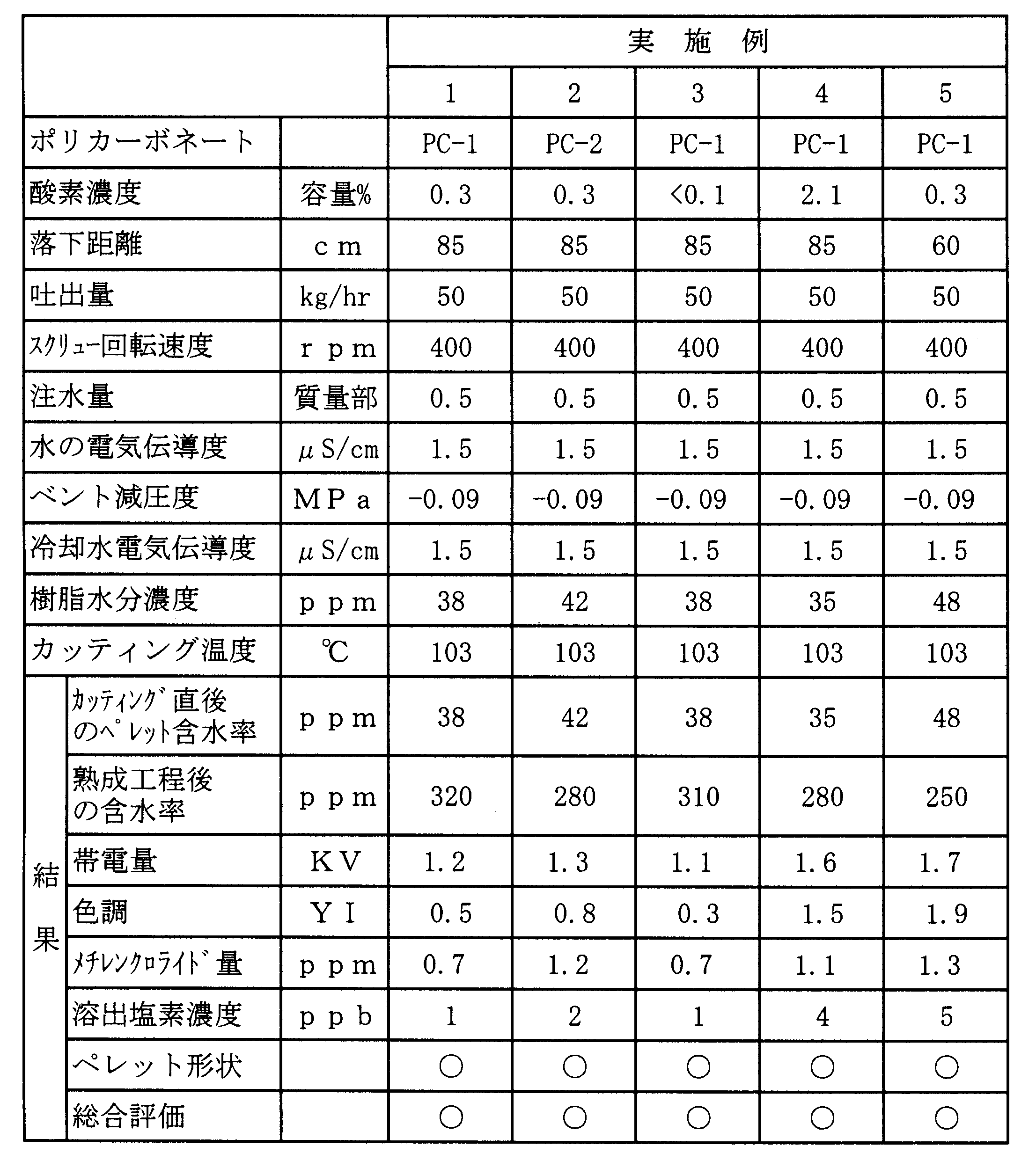

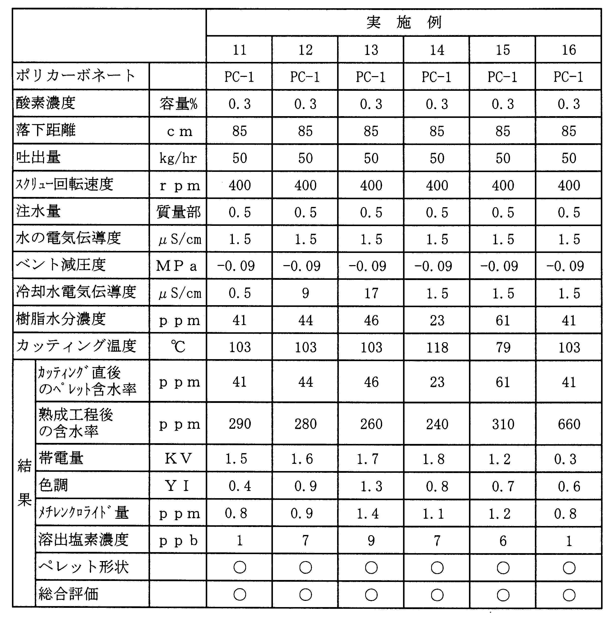
PC-1の代わりにPC-3を用いた以外は実施例1と同様にして、ペレットの製造を行った。結果を表6に示す。
窒素ガスの供給量を減らし、ホッパーシュート内の酸素濃度を4.0容量%とした以外は実施例1と同様にして、ぺレットの製造を行った。結果を表6に示す。
(比較例3)
窒素の供給をやめ、ホッパーシュート内の酸素濃度を21容量%とした他は実施例1と同様にして、ぺレットの製造を行った。結果を表6に示す。
定量フィーダーの材料供給口から二軸押出機の材料供給口までの距離(垂直高さ)を40cmに設定した以外は実施例1と同様にして、ぺレットの製造を行った。結果を表6に示す。
二床三塔型純水装置による純水と水道水とを混ぜて、電気伝導度33μS/cmの水を注水した以外は実施例1と同様にして、ペレットの製造を行った。結果を表7に示す。
(比較例6)
水槽に二床三塔型純水装置による純水と水道水とを混ぜて、電気伝導度33μS/cmの水を満たし、ストランドを冷却した他は実施例1と同様にして、ペレットの製造を行った。結果を表7に示す。
注水をやめた以外は実施例1と同様にして、ペレットの製造を行った。結果を表7に示す。
(比較例8)
注水量を0.05質量部とした以外は実施例1と同様にして、ペレットの製造を行った。結果を表7に示す。
注水量を2.5質量部とした以外は実施例1と同様にして、ペレットの製造を行った。結果を表7に示す。
押出し終了時にベントを空けると樹脂が上がって来ていた(ベントアップ。長時間の連続生産では真空系が樹脂により閉塞する可能性があり、安定生産は無理と判断された)。
水槽冷却距離を短くし、カッティング時のストランド温度を132℃まで上げた以外は実施例1と同様にして、ペレットの製造を行った。結果を表8に示す。
(比較例12)
水槽冷却距離を長くし、カッティング時のストランド温度を65℃まで下げた以外は実施例1と同様にして、ペレットの製造を行った。結果を表8に示す。
(比較例13)
実施例1において、熟成工程を経ずペレットの帯電量を測定した。帯電量は10.2kVであり、空気中の塵が吸着し易かった。結果を表8に示す。
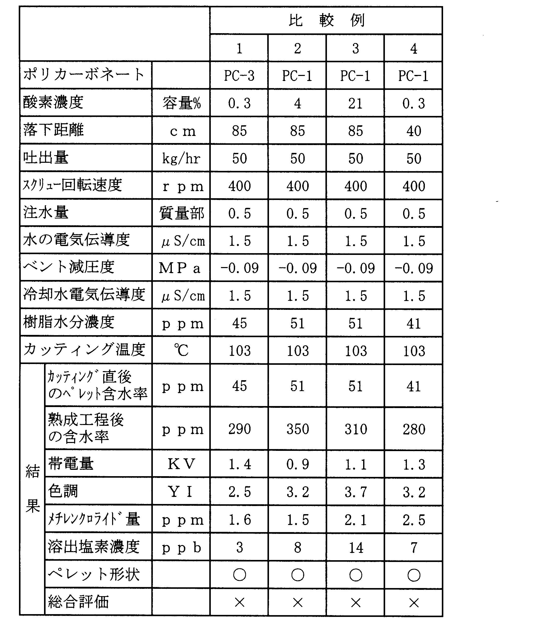

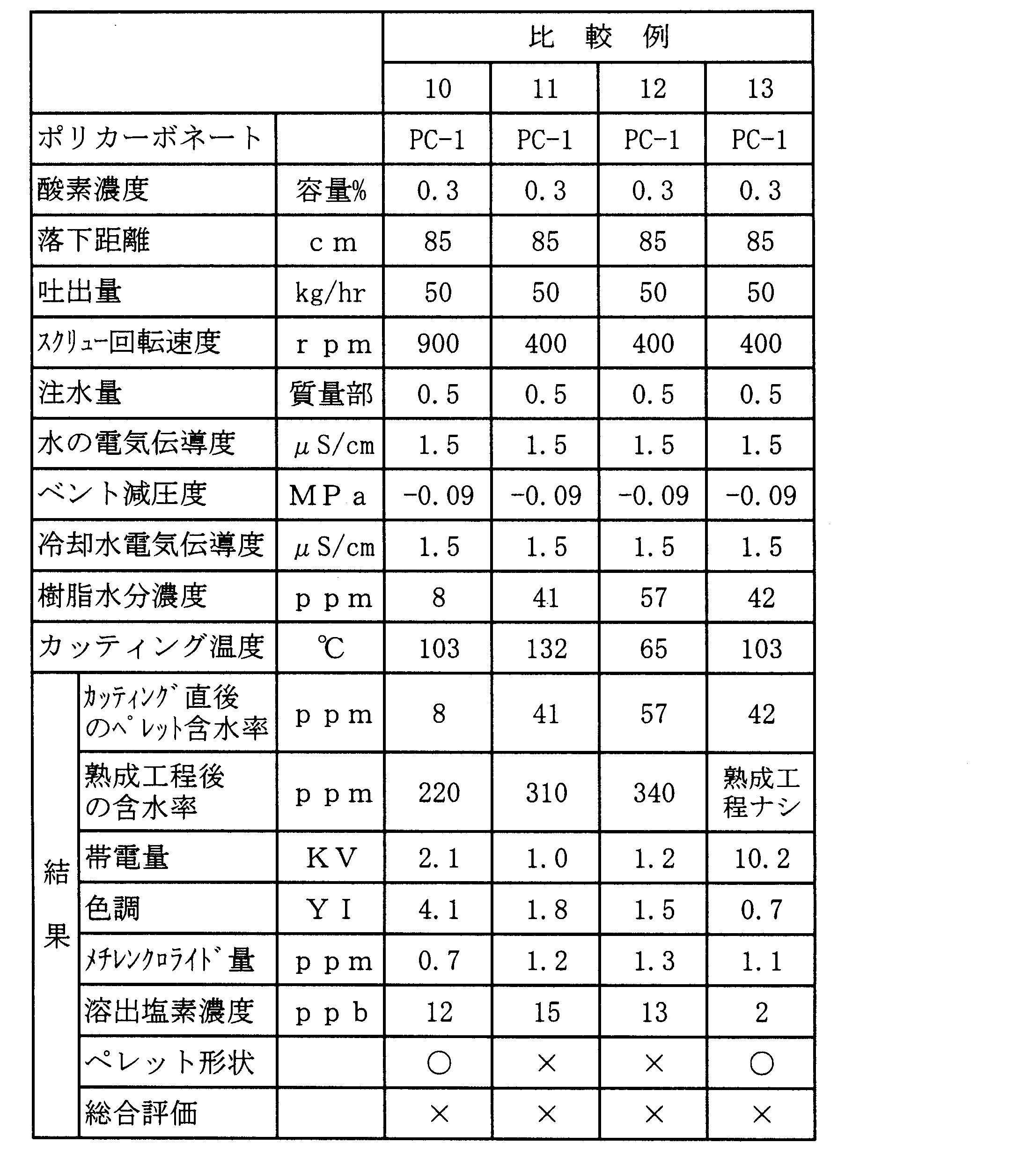
スクリュー回転数を700rpmにした以外は実施例1と同様にして、ペレットの製造を行った。
結果を表9に示す。
(実施例18)
吐出量を70kg/hr、スクリュー回転数を300rpmにした他は実施例1と同様にしてペレットの製造を行った。結果を表9に示す。
スクリュー構成を、図3のスクリュー構成Bとした以外は実施例18と同様にして、ペレットを製造した。スクリュー構成Bとは、スクリュー構成Aの減圧ゾーンのスクリューのリードを1.0Dとした構成である。結果を表9に示す。
スクリュー構成を、図3のスクリュー構成Cとした以外は実施例1と同様にして、ペレットを製造した。
スクリュー構成Cとは、以下の構成を有する。
a)溶融ゾーン:長さ31.5D、リード1.5Dの順送りスクリューを連結した。
b)混練ゾーン:長さ4.5D
送り方向に向かって、順送りニーディングエレメント1.0D、逆送りニーディングエレメント0.5D及び順送りニーディングエレメント1.0D、直交ニーディングエレメント1.0D、逆送りニーディング1.0からなる。
c)減圧ゾーン:長さ16.5D、リード1.5Dの順送りスクリューを連結した。
結果を表9に示す。
スクリュー構成を、図3のスクリュー構成Dとした以外は実施例1と同様にして、ペレットを製造した。
a)溶融ゾーン:長さ41.5D、リード1.5Dの順送りスクリューを連結した。
b)混練ゾーン:長さ4.0D
送り方向に向かって、順送りニーディングエレメント1D、逆送りニーディングエレメント0.5D及び順送りニーディングエレメント1.0D、直交ニーディングエレメント1.0D、逆送りスクリュー0.5Dからなる。なお、C13シリンダーには液注プラグを取り付け、プランジャーポンプで水を添加した。
c)減圧ゾーン:長さ7.0D、リード1.5Dの順送りスクリューを連結した。この樹脂送りゾーンを減圧部の長さとした。
結果を表9に示す。
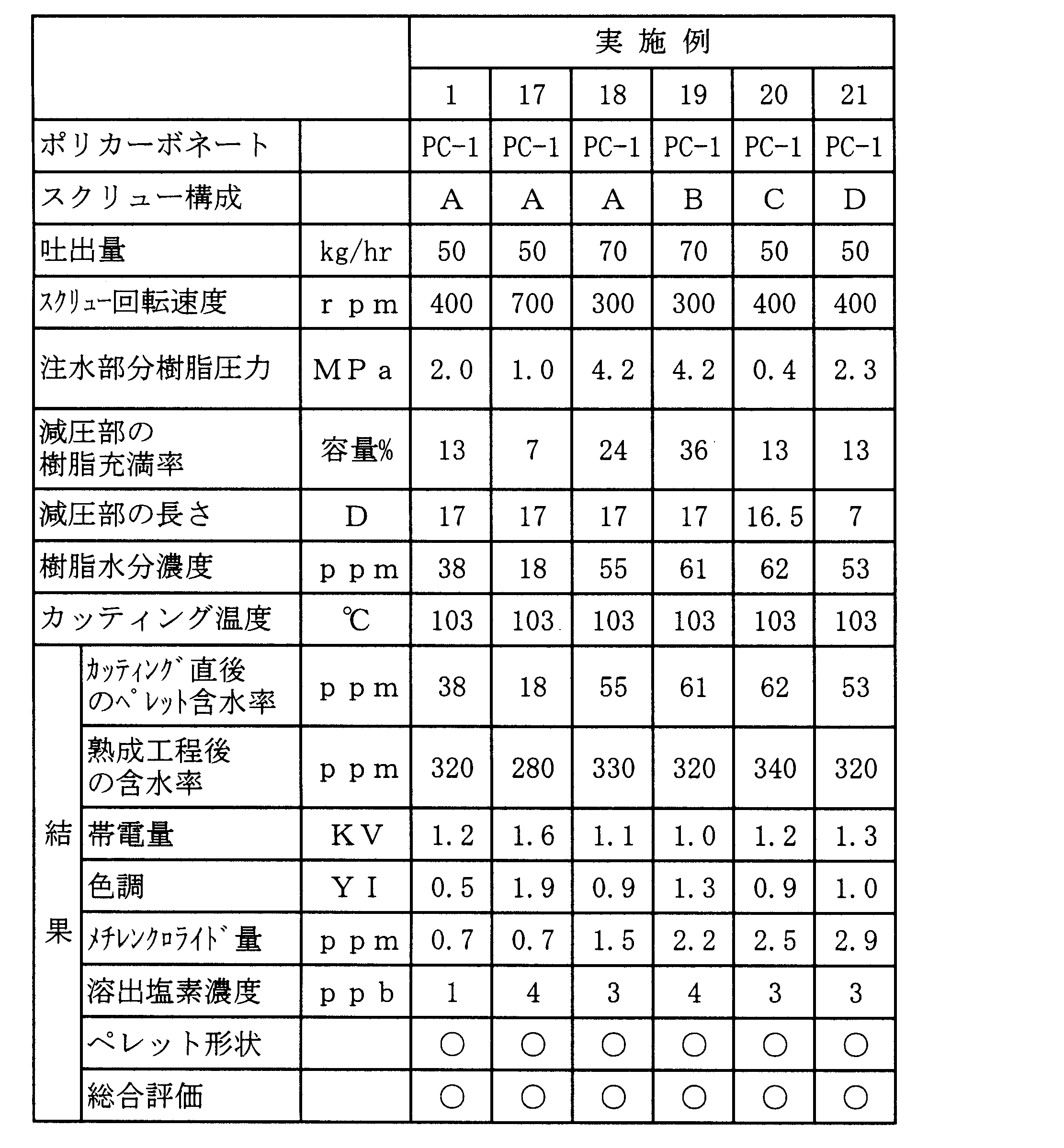
実施例1において、ペレットを乾燥すること無しに、住友重機社製射出成形機SH100を用い、シリンダー温度290℃、金型温度80℃の条件で、100mm×100mm×3mmの平板状の成形品を成形した。極めて僅かながらシルバーストリーク(銀条)が見られたが問題の無い範囲であった。
Claims (9)
- 微量のメチレンクロライドを含有するポリカーボネート樹脂から、メチレンクロライド含有量が低減されたポリカーボネート樹脂ペレットを製造する方法であって、
1)微量のメチレンクロライドを含有するポリカーボネートとして比表面積が0.008m2/g以上で、50質量%以上が200~2,000μmの粒径を有する粉粒体形状のポリカーボネート樹脂を用い、
2)粉粒体形状のポリカーボネート樹脂を、酸素濃度が3容量%以下の不活性ガス雰囲気中を50cm以上落下移動させる不活性ガス処理工程、
3)不活性ガス処理された粉粒体形状のポリカーボネート樹脂をベント式押出機に供給し、混練ゾーンにおいて、電気伝導度が30μS/cm以下である水を、ポリカーボネート樹脂100質量部に対し0.1~2質量部注入する工程、
4)押出機の水注入部より下流側に設けられたベント口を減圧状態にして吸引することにより、溶融状態の樹脂から前記水と共にメチレンクロライドを吸引除去すると共に、樹脂中の水分濃度を10~200ppmに調整する工程、
5)押出機のダイから押し出されたストランド状の溶融樹脂を電気伝導度が30μS/cm以下である水中に導入して冷却する工程、
6)ストランドを70℃~130℃の範囲でカッティングし、水分を10~200ppm含水するペレットを得る工程、
7)得られた、水分を10~200ppm含有するペレットを湿潤雰囲気下に置くことにより更に含水させ、含水率を、ペレットの元の含水率を超え、1300ppm以下に調整する熟成工程
を含むことを特徴とするポリカーボネート樹脂ペレットの製造方法。 - 熟成工程を経て得られた含水状態のペレットを乾燥する乾燥工程を更に行うことを特徴とする請求項1に記載のポリカーボネート樹脂ペレットの製造方法。
- 粉粒体形状のポリカーボネート樹脂を不活性ガスで処理するに当たり、粉流体を落下状態で供給し、不活性ガスを下方から、粉粒体に対して向流となるように供給することを特徴とする請求項1に記載のポリカーボネート樹脂ペレットの製造方法。
- ベント式押出機のバレル中の酸素濃度を3容量%以下とすることを特徴とする請求項1に記載のポリカーボネート樹脂ペレットの製造方法。
- 水を注入する混練ゾーンが、樹脂の充満領域であり、樹脂圧力が0.5~10MPaの範囲であることを特徴とする請求項1に記載のポリカーボネート樹脂ペレットの製造方法。
- 押出機の減圧部での樹脂充満率が5~30容量%である領域の長さが、8.0D(Dは押出機のシリンダー内径)以上であることを特徴とする請求項1に記載のポリカーボネート樹脂ペレットの製造方法。
- ストランドを冷却する水の温度が30~90℃であることを特徴とする請求項1に記載のポリカーボネート樹脂ペレットの製造方法。
- 請求項1に記載の製造方法で製造されたポリカーボネート樹脂ペレット。
- 請求項8に記載のポリカーボネート樹脂ペレットを用いたことを特徴とする電気電子機器部品搬送用ケース。
Priority Applications (2)
| Application Number | Priority Date | Filing Date | Title |
|---|---|---|---|
| KR1020127014144A KR101201265B1 (ko) | 2011-02-09 | 2012-01-19 | 폴리카보네이트 수지 펠릿의 제조 방법 |
| CN201280000639.9A CN102781640B (zh) | 2011-02-09 | 2012-01-19 | 聚碳酸酯树脂粒料的制造方法 |
Applications Claiming Priority (2)
| Application Number | Priority Date | Filing Date | Title |
|---|---|---|---|
| JP2011025860A JP4977786B1 (ja) | 2011-02-09 | 2011-02-09 | ポリカーボネート樹脂ペレットの製造方法 |
| JP2011-025860 | 2011-02-09 |
Publications (1)
| Publication Number | Publication Date |
|---|---|
| WO2012108245A1 true WO2012108245A1 (ja) | 2012-08-16 |
Family
ID=46638463
Family Applications (1)
| Application Number | Title | Priority Date | Filing Date |
|---|---|---|---|
| PCT/JP2012/051052 Ceased WO2012108245A1 (ja) | 2011-02-09 | 2012-01-19 | ポリカーボネート樹脂ペレットの製造方法 |
Country Status (4)
| Country | Link |
|---|---|
| JP (1) | JP4977786B1 (ja) |
| KR (1) | KR101201265B1 (ja) |
| CN (1) | CN102781640B (ja) |
| WO (1) | WO2012108245A1 (ja) |
Cited By (7)
| Publication number | Priority date | Publication date | Assignee | Title |
|---|---|---|---|---|
| CN104710636A (zh) * | 2015-02-16 | 2015-06-17 | 聊城鲁西聚碳酸酯有限公司 | 一种制备聚碳酸酯薄片的系统和工艺 |
| JPWO2014148577A1 (ja) * | 2013-03-21 | 2017-02-16 | 日本ゼオン株式会社 | リチウムイオン二次電池多孔膜用スラリー及びその製造方法、リチウムイオン二次電池用セパレータ並びにリチウムイオン二次電池 |
| EP3900910A4 (en) * | 2019-11-25 | 2022-03-16 | LG Chem, Ltd. | EXTRUDING DEVICE |
| EP3900909A4 (en) * | 2019-11-25 | 2022-03-23 | LG Chem, Ltd. | EXTRUSION DEVICE |
| LU502091B1 (en) * | 2022-05-13 | 2023-11-13 | saperatec GmbH | Method and apparatus for removing low molecular impurities from an impure extrudable material |
| WO2024195353A1 (ja) * | 2023-03-23 | 2024-09-26 | 株式会社豊田中央研究所 | 樹脂組成物の製造方法及び樹脂組成物の製造装置 |
| EP4640403A1 (de) * | 2024-04-22 | 2025-10-29 | Covestro Deutschland AG | Inertisierung von teilgefüllten extrudereinläufen |
Families Citing this family (13)
| Publication number | Priority date | Publication date | Assignee | Title |
|---|---|---|---|---|
| JP6264809B2 (ja) * | 2012-09-26 | 2018-01-24 | 三菱ケミカル株式会社 | ポリカーボネート樹脂の製造方法 |
| JP6247515B2 (ja) * | 2013-12-06 | 2017-12-13 | 帝人株式会社 | 成形品およびその製造方法 |
| JP6464835B2 (ja) * | 2015-03-09 | 2019-02-06 | 三菱エンジニアリングプラスチックス株式会社 | 芳香族ポリカーボネート樹脂成形品の製造方法 |
| JP6543969B2 (ja) * | 2015-03-09 | 2019-07-17 | 三菱エンジニアリングプラスチックス株式会社 | 芳香族ポリカーボネート樹脂成形品の製造方法 |
| CN107922629B (zh) * | 2015-08-11 | 2021-03-30 | 三菱工程塑料株式会社 | 聚碳酸酯树脂颗粒和其制造方法 |
| WO2017159727A1 (ja) * | 2016-03-15 | 2017-09-21 | 出光興産株式会社 | ポリカーボネート樹脂、ポリカーボネート樹脂の製造方法、塗工液、電子写真感光体、および電子写真装置 |
| KR20180078906A (ko) * | 2016-12-30 | 2018-07-10 | 롯데첨단소재(주) | 정밀 부재용 수납 용기 및 이의 제조방법 |
| JP7037721B2 (ja) * | 2017-12-08 | 2022-03-17 | 日立金属株式会社 | 感圧センサおよび感圧センサの製造方法 |
| CN114536583A (zh) * | 2022-01-17 | 2022-05-27 | 中山市武汉理工大学先进工程技术研究院 | 一种充分除氧的热塑性树脂高温熔融挤出成型、造粒方法 |
| JP7858477B2 (ja) * | 2022-08-24 | 2026-05-14 | 三菱エンジニアリングプラスチックス株式会社 | 繊維状充填材の攪拌供給装置、供給方法、製造方法、及び熱可塑性樹脂組成物の製造方法 |
| CN119698348A (zh) * | 2022-08-24 | 2025-03-25 | 三菱工程塑料株式会社 | 纤维状填料的搅拌和供给装置、供给方法、和生产方法、以及热塑性树脂组合物的生产方法 |
| US20260001261A1 (en) * | 2022-09-01 | 2026-01-01 | Mitsubishi Gas Chemical Company, Inc. | Method for producing polycarbonate resin molded product |
| WO2026042591A1 (ja) * | 2024-08-22 | 2026-02-26 | 帝人株式会社 | リサイクルポリカーボネート樹脂粒子およびその製造方法 |
Citations (5)
| Publication number | Priority date | Publication date | Assignee | Title |
|---|---|---|---|---|
| JPH0966524A (ja) * | 1995-06-20 | 1997-03-11 | Mitsubishi Gas Chem Co Inc | ポリカーボネート樹脂ペレットの製造法 |
| JPH09254151A (ja) * | 1996-01-16 | 1997-09-30 | Asahi Chem Ind Co Ltd | ポリカーボネートペレット及びその製造方法 |
| JP2003094435A (ja) * | 2001-09-25 | 2003-04-03 | Teijin Ltd | 結晶性芳香族ポリカーボネート粒状成形体の製造方法 |
| JP2008018594A (ja) * | 2006-07-12 | 2008-01-31 | Teijin Chem Ltd | ポリカーボネート樹脂ペレットの製造方法および該ペレットから形成されたシリコンウエハーまたは磁気ディスクの収納搬送容器 |
| JP2009184266A (ja) * | 2008-02-07 | 2009-08-20 | Mitsubishi Engineering Plastics Corp | ポリカーボネート樹脂成形体の成形装置、成形方法及びポリカーボネート樹脂成形体 |
Family Cites Families (7)
| Publication number | Priority date | Publication date | Assignee | Title |
|---|---|---|---|---|
| JPH0266524A (ja) * | 1988-09-01 | 1990-03-06 | Konica Corp | 波長変換素子 |
| JPH0454151A (ja) * | 1990-06-25 | 1992-02-21 | Seiko Epson Corp | エステル化合物 |
| JP2000052402A (ja) * | 1998-08-05 | 2000-02-22 | Teijin Chem Ltd | 芳香族ポリカーボネート成形品の製造方法 |
| US7112644B2 (en) * | 2002-01-23 | 2006-09-26 | Idemitsu Kosan Co., Ltd. | Aromatic polycarbonate resin, process for producing the same, optical-part molding material, and optical part |
| JP4544043B2 (ja) * | 2005-06-08 | 2010-09-15 | 三菱エンジニアリングプラスチックス株式会社 | 粉体原料の供給装置および供給方法 |
| EP2108671A4 (en) * | 2007-02-02 | 2012-02-15 | Teijin Ltd | POLYCARBONATE RESIN AND METHOD FOR PRODUCING THE SAME |
| JP5324354B2 (ja) * | 2009-08-12 | 2013-10-23 | 三菱エンジニアリングプラスチックス株式会社 | ポリカーボネート樹脂成形材料の製造方法 |
-
2011
- 2011-02-09 JP JP2011025860A patent/JP4977786B1/ja active Active
-
2012
- 2012-01-19 KR KR1020127014144A patent/KR101201265B1/ko active Active
- 2012-01-19 CN CN201280000639.9A patent/CN102781640B/zh active Active
- 2012-01-19 WO PCT/JP2012/051052 patent/WO2012108245A1/ja not_active Ceased
Patent Citations (5)
| Publication number | Priority date | Publication date | Assignee | Title |
|---|---|---|---|---|
| JPH0966524A (ja) * | 1995-06-20 | 1997-03-11 | Mitsubishi Gas Chem Co Inc | ポリカーボネート樹脂ペレットの製造法 |
| JPH09254151A (ja) * | 1996-01-16 | 1997-09-30 | Asahi Chem Ind Co Ltd | ポリカーボネートペレット及びその製造方法 |
| JP2003094435A (ja) * | 2001-09-25 | 2003-04-03 | Teijin Ltd | 結晶性芳香族ポリカーボネート粒状成形体の製造方法 |
| JP2008018594A (ja) * | 2006-07-12 | 2008-01-31 | Teijin Chem Ltd | ポリカーボネート樹脂ペレットの製造方法および該ペレットから形成されたシリコンウエハーまたは磁気ディスクの収納搬送容器 |
| JP2009184266A (ja) * | 2008-02-07 | 2009-08-20 | Mitsubishi Engineering Plastics Corp | ポリカーボネート樹脂成形体の成形装置、成形方法及びポリカーボネート樹脂成形体 |
Cited By (12)
| Publication number | Priority date | Publication date | Assignee | Title |
|---|---|---|---|---|
| JPWO2014148577A1 (ja) * | 2013-03-21 | 2017-02-16 | 日本ゼオン株式会社 | リチウムイオン二次電池多孔膜用スラリー及びその製造方法、リチウムイオン二次電池用セパレータ並びにリチウムイオン二次電池 |
| US11095000B2 (en) | 2013-03-21 | 2021-08-17 | Zeon Corporation | Slurry for lithium ion secondary battery porous film, production method therefor, separator for lithium ion secondary battery, and lithium ion secondary battery |
| CN104710636A (zh) * | 2015-02-16 | 2015-06-17 | 聊城鲁西聚碳酸酯有限公司 | 一种制备聚碳酸酯薄片的系统和工艺 |
| EP3900910A4 (en) * | 2019-11-25 | 2022-03-16 | LG Chem, Ltd. | EXTRUDING DEVICE |
| EP3900909A4 (en) * | 2019-11-25 | 2022-03-23 | LG Chem, Ltd. | EXTRUSION DEVICE |
| US12304111B2 (en) | 2019-11-25 | 2025-05-20 | Lg Chem, Ltd. | Extruder |
| US12390975B2 (en) | 2019-11-25 | 2025-08-19 | Lg Chem, Ltd. | Extruder |
| LU502091B1 (en) * | 2022-05-13 | 2023-11-13 | saperatec GmbH | Method and apparatus for removing low molecular impurities from an impure extrudable material |
| WO2023218070A1 (en) | 2022-05-13 | 2023-11-16 | saperatec GmbH | Method and apparatus for removing impurities from an impure extrudable material |
| WO2024195353A1 (ja) * | 2023-03-23 | 2024-09-26 | 株式会社豊田中央研究所 | 樹脂組成物の製造方法及び樹脂組成物の製造装置 |
| EP4640403A1 (de) * | 2024-04-22 | 2025-10-29 | Covestro Deutschland AG | Inertisierung von teilgefüllten extrudereinläufen |
| WO2025223903A1 (de) * | 2024-04-22 | 2025-10-30 | Covestro Deutschland Ag | Inertisierung von teilgefüllten extrudereinläufen |
Also Published As
| Publication number | Publication date |
|---|---|
| JP4977786B1 (ja) | 2012-07-18 |
| JP2012162048A (ja) | 2012-08-30 |
| CN102781640A (zh) | 2012-11-14 |
| CN102781640B (zh) | 2014-03-12 |
| KR20120101665A (ko) | 2012-09-14 |
| KR101201265B1 (ko) | 2012-11-14 |
Similar Documents
| Publication | Publication Date | Title |
|---|---|---|
| JP4977786B1 (ja) | ポリカーボネート樹脂ペレットの製造方法 | |
| CN105431488B (zh) | 薄壁光学构件用聚碳酸酯树脂组合物及薄壁光学构件 | |
| CN102597110B (zh) | 聚碳酸酯树脂组合物和成型品 | |
| KR102520297B1 (ko) | 폴리카보네이트 수지 펠릿들 및 이의 제조 방법 | |
| JP6275077B2 (ja) | ポリカーボネート樹脂組成物 | |
| KR20120115234A (ko) | 폴리카보네이트 수지 조성물 및 성형품 | |
| WO2012111721A1 (ja) | ポリカーボネート樹脂組成物 | |
| KR20180014821A (ko) | 폴리머의 탈수 방법 및 그로부터 제조된 폴리머 | |
| JP2017226848A (ja) | ポリカーボネート樹脂成形品の製造方法、およびポリカーボネート樹脂成形品 | |
| CN103476561A (zh) | 聚碳酸酯树脂的制造方法、聚碳酸酯树脂、聚碳酸酯树脂制膜及聚碳酸酯树脂颗粒的制造方法 | |
| CN105307827B (zh) | 薄壁光学构件用聚碳酸酯树脂颗粒及其制造方法 | |
| KR20120117755A (ko) | 폴리카보네이트 수지 조성물 및 성형품 | |
| CN102712804A (zh) | 聚碳酸酯树脂组合物和成型品 | |
| JP6464835B2 (ja) | 芳香族ポリカーボネート樹脂成形品の製造方法 | |
| JP6056248B2 (ja) | ポリカーボネート樹脂の製造方法 | |
| JP6163794B2 (ja) | ポリカーボネートの製造方法 | |
| JP2012067294A (ja) | ポリカーボネート樹脂組成物及び成形品 | |
| JP2010275466A (ja) | ポリカーボネート樹脂ペレット、その製造方法および成形品 | |
| JP7826757B2 (ja) | ポリカーボネート樹脂組成物及び成形品 | |
| JP2022027579A (ja) | ポリカーボネート樹脂組成物ペレットの製造方法 | |
| JP2022027580A (ja) | ポリカーボネート樹脂組成物ペレットの製造方法 | |
| JP2022027581A (ja) | ポリカーボネート樹脂組成物ペレットの製造方法 | |
| JP2015183087A (ja) | ポリカーボネート樹脂の製造方法 | |
| JP2016113571A (ja) | 超臨界発泡成形用ポリカーボネート樹脂組成物及び成形品 |
Legal Events
| Date | Code | Title | Description |
|---|---|---|---|
| WWE | Wipo information: entry into national phase |
Ref document number: 201280000639.9 Country of ref document: CN |
|
| ENP | Entry into the national phase |
Ref document number: 20127014144 Country of ref document: KR Kind code of ref document: A |
|
| 121 | Ep: the epo has been informed by wipo that ep was designated in this application |
Ref document number: 12745024 Country of ref document: EP Kind code of ref document: A1 |
|
| NENP | Non-entry into the national phase |
Ref country code: DE |
|
| 122 | Ep: pct application non-entry in european phase |
Ref document number: 12745024 Country of ref document: EP Kind code of ref document: A1 |