WO2012105491A1 - 蓄電素子 - Google Patents
蓄電素子 Download PDFInfo
- Publication number
- WO2012105491A1 WO2012105491A1 PCT/JP2012/051979 JP2012051979W WO2012105491A1 WO 2012105491 A1 WO2012105491 A1 WO 2012105491A1 JP 2012051979 W JP2012051979 W JP 2012051979W WO 2012105491 A1 WO2012105491 A1 WO 2012105491A1
- Authority
- WO
- WIPO (PCT)
- Prior art keywords
- exterior body
- packing
- protrusions
- external terminal
- electrode side
- Prior art date
- Legal status (The legal status is an assumption and is not a legal conclusion. Google has not performed a legal analysis and makes no representation as to the accuracy of the status listed.)
- Ceased
Links
Images






Classifications
-
- H—ELECTRICITY
- H01—ELECTRIC ELEMENTS
- H01M—PROCESSES OR MEANS, e.g. BATTERIES, FOR THE DIRECT CONVERSION OF CHEMICAL ENERGY INTO ELECTRICAL ENERGY
- H01M50/00—Constructional details or processes of manufacture of the non-active parts of electrochemical cells other than fuel cells, e.g. hybrid cells
- H01M50/10—Primary casings; Jackets or wrappings
- H01M50/102—Primary casings; Jackets or wrappings characterised by their shape or physical structure
- H01M50/103—Primary casings; Jackets or wrappings characterised by their shape or physical structure prismatic or rectangular
-
- H—ELECTRICITY
- H01—ELECTRIC ELEMENTS
- H01M—PROCESSES OR MEANS, e.g. BATTERIES, FOR THE DIRECT CONVERSION OF CHEMICAL ENERGY INTO ELECTRICAL ENERGY
- H01M10/00—Secondary cells; Manufacture thereof
- H01M10/04—Construction or manufacture in general
- H01M10/0431—Cells with wound or folded electrodes
-
- H—ELECTRICITY
- H01—ELECTRIC ELEMENTS
- H01M—PROCESSES OR MEANS, e.g. BATTERIES, FOR THE DIRECT CONVERSION OF CHEMICAL ENERGY INTO ELECTRICAL ENERGY
- H01M50/00—Constructional details or processes of manufacture of the non-active parts of electrochemical cells other than fuel cells, e.g. hybrid cells
- H01M50/10—Primary casings; Jackets or wrappings
- H01M50/147—Lids or covers
- H01M50/148—Lids or covers characterised by their shape
- H01M50/15—Lids or covers characterised by their shape for prismatic or rectangular cells
-
- H—ELECTRICITY
- H01—ELECTRIC ELEMENTS
- H01M—PROCESSES OR MEANS, e.g. BATTERIES, FOR THE DIRECT CONVERSION OF CHEMICAL ENERGY INTO ELECTRICAL ENERGY
- H01M50/00—Constructional details or processes of manufacture of the non-active parts of electrochemical cells other than fuel cells, e.g. hybrid cells
- H01M50/10—Primary casings; Jackets or wrappings
- H01M50/172—Arrangements of electric connectors penetrating the casing
- H01M50/174—Arrangements of electric connectors penetrating the casing adapted for the shape of the cells
- H01M50/176—Arrangements of electric connectors penetrating the casing adapted for the shape of the cells for prismatic or rectangular cells
-
- H—ELECTRICITY
- H01—ELECTRIC ELEMENTS
- H01M—PROCESSES OR MEANS, e.g. BATTERIES, FOR THE DIRECT CONVERSION OF CHEMICAL ENERGY INTO ELECTRICAL ENERGY
- H01M50/00—Constructional details or processes of manufacture of the non-active parts of electrochemical cells other than fuel cells, e.g. hybrid cells
- H01M50/10—Primary casings; Jackets or wrappings
- H01M50/183—Sealing members
- H01M50/184—Sealing members characterised by their shape or structure
-
- H—ELECTRICITY
- H01—ELECTRIC ELEMENTS
- H01M—PROCESSES OR MEANS, e.g. BATTERIES, FOR THE DIRECT CONVERSION OF CHEMICAL ENERGY INTO ELECTRICAL ENERGY
- H01M50/00—Constructional details or processes of manufacture of the non-active parts of electrochemical cells other than fuel cells, e.g. hybrid cells
- H01M50/10—Primary casings; Jackets or wrappings
- H01M50/183—Sealing members
- H01M50/186—Sealing members characterised by the disposition of the sealing members
- H01M50/188—Sealing members characterised by the disposition of the sealing members the sealing members being arranged between the lid and terminal
-
- H—ELECTRICITY
- H01—ELECTRIC ELEMENTS
- H01M—PROCESSES OR MEANS, e.g. BATTERIES, FOR THE DIRECT CONVERSION OF CHEMICAL ENERGY INTO ELECTRICAL ENERGY
- H01M50/00—Constructional details or processes of manufacture of the non-active parts of electrochemical cells other than fuel cells, e.g. hybrid cells
- H01M50/50—Current conducting connections for cells or batteries
- H01M50/531—Electrode connections inside a battery casing
- H01M50/538—Connection of several leads or tabs of wound or folded electrode stacks
-
- H—ELECTRICITY
- H01—ELECTRIC ELEMENTS
- H01M—PROCESSES OR MEANS, e.g. BATTERIES, FOR THE DIRECT CONVERSION OF CHEMICAL ENERGY INTO ELECTRICAL ENERGY
- H01M50/00—Constructional details or processes of manufacture of the non-active parts of electrochemical cells other than fuel cells, e.g. hybrid cells
- H01M50/50—Current conducting connections for cells or batteries
- H01M50/543—Terminals
- H01M50/547—Terminals characterised by the disposition of the terminals on the cells
- H01M50/55—Terminals characterised by the disposition of the terminals on the cells on the same side of the cell
-
- H—ELECTRICITY
- H01—ELECTRIC ELEMENTS
- H01M—PROCESSES OR MEANS, e.g. BATTERIES, FOR THE DIRECT CONVERSION OF CHEMICAL ENERGY INTO ELECTRICAL ENERGY
- H01M50/00—Constructional details or processes of manufacture of the non-active parts of electrochemical cells other than fuel cells, e.g. hybrid cells
- H01M50/50—Current conducting connections for cells or batteries
- H01M50/543—Terminals
- H01M50/552—Terminals characterised by their shape
- H01M50/553—Terminals adapted for prismatic, pouch or rectangular cells
-
- Y—GENERAL TAGGING OF NEW TECHNOLOGICAL DEVELOPMENTS; GENERAL TAGGING OF CROSS-SECTIONAL TECHNOLOGIES SPANNING OVER SEVERAL SECTIONS OF THE IPC; TECHNICAL SUBJECTS COVERED BY FORMER USPC CROSS-REFERENCE ART COLLECTIONS [XRACs] AND DIGESTS
- Y02—TECHNOLOGIES OR APPLICATIONS FOR MITIGATION OR ADAPTATION AGAINST CLIMATE CHANGE
- Y02E—REDUCTION OF GREENHOUSE GAS [GHG] EMISSIONS, RELATED TO ENERGY GENERATION, TRANSMISSION OR DISTRIBUTION
- Y02E60/00—Enabling technologies; Technologies with a potential or indirect contribution to GHG emissions mitigation
- Y02E60/10—Energy storage using batteries
-
- Y—GENERAL TAGGING OF NEW TECHNOLOGICAL DEVELOPMENTS; GENERAL TAGGING OF CROSS-SECTIONAL TECHNOLOGIES SPANNING OVER SEVERAL SECTIONS OF THE IPC; TECHNICAL SUBJECTS COVERED BY FORMER USPC CROSS-REFERENCE ART COLLECTIONS [XRACs] AND DIGESTS
- Y02—TECHNOLOGIES OR APPLICATIONS FOR MITIGATION OR ADAPTATION AGAINST CLIMATE CHANGE
- Y02P—CLIMATE CHANGE MITIGATION TECHNOLOGIES IN THE PRODUCTION OR PROCESSING OF GOODS
- Y02P70/00—Climate change mitigation technologies in the production process for final industrial or consumer products
- Y02P70/50—Manufacturing or production processes characterised by the final manufactured product
Definitions
- the present invention relates to a storage element including a battery such as a non-electrolyte secondary battery.
- a positive electrode and a negative electrode of an electrode body accommodated in a battery container are electrically connected to positive and negative external terminals via a positive and negative current collector. At least a part of the external terminals is disposed on the upper surface (outer surface) of the lid that seals the upper end opening of the battery container. An upper packing for insulation is interposed between the external terminal and the upper surface of the lid.
- a protrusion that protrudes upward from the upper surface of the lid body is passed through a portion (protrusion portion) different from the portion where the external terminals are arranged in the upper packing, and the upper surface of the lid body is formed.
- the upper packing is prevented from rotating.
- the protrusion provided in the upper packing described in Patent Document 1 is a simple plate shape. Providing such a plate-like protrusion is contrary to the demand for weight reduction of the upper packing and material saving required for manufacturing the upper packing.
- the protrusions are squeezed and joined to the lid by spreading the tips of the protrusions in order to prevent reliable rotation and prevent the upper packing from coming off the lid during manufacturing, There is little room for deformation (escape) in the surface direction against compression of the. Therefore, there is a possibility that damage such as cracking may occur in the protruding portion during caulking and joining. In other words, a simple plate-like protrusion is not suitable for caulking.
- An object of the present invention is to reliably prevent the packing from rotating relative to the lid while reducing the weight and material.
- the first aspect of the present invention is: An exterior body, an external terminal having an exposed surface exposed to the outside from the exterior body, a current collector disposed inside the exterior body and connected to the external terminal, and disposed inside the exterior body, to the current collector
- An electrical storage element comprising: an electrode body to be connected;
- the exterior body includes a plurality of protrusions protruding outward,
- a packing having a main body interposed between the external terminal and the outer package, and a plurality of projecting portions each extending from the main body and having an insertion hole through which each projection of the outer package is inserted,
- Each of the protrusions is configured to be caulked and joined to the exterior body after being inserted through the insertion holes of the protrusions.
- the packing has a configuration including a main body and a plurality of projecting portions extending from the main body, and a projection is inserted into an insertion hole of each projecting portion so as to be caulked and joined to the exterior body. That is, since it is the structure which only formed the protrusion part as a location required for crimping joining, the weight reduction of a packing and the material reduction required for the manufacture can be aimed at. In addition, since the plurality of protrusions extend separately from the main body, it is possible to secure room for deformation (escape) in the surface direction against compression in the thickness direction of the individual protrusions during caulking and joining by the protrusions, and packing during caulking and joining. Damages such as cracks can be reliably prevented. As a result, since the protruding portion can be securely caulked and joined to the lid body, the rotation of the packing with respect to the exterior body can be reliably prevented, and the packing can also be reliably prevented from being detached from the exterior body during manufacture.
- the projecting portion of the packing is composed of a plurality of adjacently arranged with an interval, You may make it comprise the protrusion of the said exterior body by the plurality which can be arrange
- the protruding portion of the packing is composed of a plurality of at least one disposed on the opposite side across the main body, You may make it comprise the protrusion of the said exterior body by the plurality which can be arrange
- the protrusions of the exterior body may be integrated with another member in the exterior body.
- the projection of the exterior body may be configured by projecting a part of the exterior body.
- the protrusion can be formed easily and inexpensively by press working or the like.
- the external terminal comprises a positive terminal and a negative terminal
- the protrusions of the outer package have different shapes on the positive electrode side and the negative electrode side, It is preferable that the insertion holes formed in the protruding portions of the packing disposed on the positive electrode side and the negative electrode side have a shape that allows only the corresponding protrusions to be inserted.
- the external terminal comprises a positive terminal and a negative terminal,
- the protrusions of the outer package may be shifted in position between the positive electrode side and the negative electrode side.
- the second aspect of the present invention is as follows.
- An electrical storage element comprising: an electrode body to be connected;
- the external terminal comprises a positive terminal and a negative terminal,
- the exterior body is formed with a pair of bulging portions that bulge outward, and a protrusion that is formed in the vicinity of each bulging portion and projects outward.
- a packing further comprising a main body interposed between the external terminal and the outer package, and a protrusion that extends from the main body and has an insertion hole through which a protrusion of the outer package is inserted,
- the protrusion is configured to be caulked and joined to the exterior body after being inserted into the insertion hole of the protrusion.
- the shape of the bulging portion of the outer package is different between the positive electrode side and the negative electrode side.
- the packing includes a main body and a plurality of protrusions extending from the main body, and the protrusions are inserted into the insertion holes of the protrusions to be caulked and joined to the exterior body. Therefore, while reducing the weight of the packing and reducing the material required for its manufacture, it is possible to reliably prevent the packing from rotating with respect to the exterior body, and to reliably prevent the packing from being detached from the exterior body during manufacture.
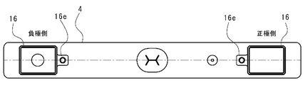
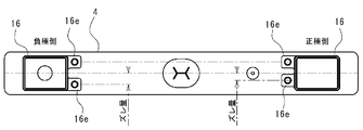
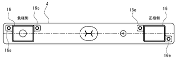
- FIG. 6 is a plan view of an upper packing on the positive electrode side of a battery according to still another embodiment of the present invention. It is a top view of the battery which concerns on other embodiment of this invention.
- FIG. 6 is a plan view of an upper packing on the positive electrode side of a battery according to still another embodiment of the present invention. It is a top view of the battery which concerns on other embodiment of this invention. It is a top view of the battery which concerns on other embodiment of this invention. It is a top view of the battery which concerns on other embodiment of this invention. It is a top view of the battery which concerns on other embodiment of this invention.
- a non-aqueous electrolyte secondary battery 1 (hereinafter simply referred to as a battery) according to an embodiment of the present invention.
- a battery a non-aqueous electrolyte secondary battery 1 (hereinafter simply referred to as a battery) according to an embodiment of the present invention.
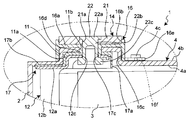
- an electrode body 3 is accommodated in a rectangular battery container 2 made of aluminum, an aluminum alloy, or the like, and an upper end opening of the battery container 2 is sealed with a lid body 4.
- the battery container 2 and the lid 4 constitute a substantially rectangular parallelepiped exterior body.
- the upper surfaces of the negative external terminal 14 and the positive external terminal 15 are exposed to the outside of the lid 4.
- the electrode body 3 is formed by arranging and winding a separator made of a porous resin film between a negative electrode made of copper foil and a positive electrode made of aluminum foil.
- the electrode body 3 has a negative electrode electrically connected to the negative electrode external terminal 14 via the negative electrode current collector 12, and a positive electrode electrically connected to the positive electrode external terminal 15 via the positive electrode current collector 13.
- the lid 4 is a long metal plate having a rectangular shape in plan view, and a safety valve 8 is mounted near the center in the longitudinal direction, and a liquid injection hole 9 is provided on one end side. Is provided.
- engagement receiving portions (bulging portions) 11 having a substantially rectangular shape in plan view that bulges upward from the upper surface 4b are formed.
- the lower surface 4a of the cover body 4 is recessed, and the engagement recessed part 11a is formed.
- a through hole 11c is formed in the central portion of the ceiling surface that constitutes the engaging recess 11a.
- a pair of protrusions 4 c that protrude from the upper surface 4 b are formed in the vicinity of the engagement receiving portion 11 at predetermined intervals along one side thereof (sides facing each other between the engagement receiving portions 11).
- the engagement receiving portion 11, the through hole 11c, and the protrusion 4c can be formed by press working or the like.
- the protrusion 4c is formed by spot welding of another member.
- the protrusion 4c integrally with the lid 4 by pressing or the like, the number of parts does not increase, and it is simple and inexpensive. Can be manufactured without any increase in weight.
- the protrusion 4c can be formed by spot welding of another member as in the conventional case.
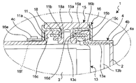
- a negative electrode current collector 12 and a negative electrode external terminal 14 are attached to the left engagement receiving portion 11 via an upper packing 16 and a negative electrode lower packing 17, respectively.
- the upper packing 16 is a resin part that partitions the upper terminal holding recess 16b and the lower mounting recess 16c by a partition wall 16a.
- the center portion of the partition wall 16a has both end openings extending downward.
- a cylindrical portion 16d is provided.
- the partition 16a, the terminal holding part 16b, the mounting recess 16c, and the cylindrical part 16d constitute the main body of the upper packing 16 in the present invention.
- the upper packing 16 is mounted on the lid 4 by covering the engagement receiving portion 11 from above and housing the engagement receiving portion 11 in the mounting recess 16c.
- the cylindrical portion 16d is inserted into the through hole 11c and enters the locking recess 11a.
- the negative electrode lower packing 17 includes a caulking portion 17a disposed in the engaging recess 11a of the lid body 4, and a flat portion 17b provided continuously to the caulking portion 17a.
- a through hole 17c is formed in the crimped portion 17a. Near the lower end of the cylindrical portion 16d of the upper packing 16 is inserted into the through hole 17c.
- the negative electrode external terminal 14 includes an aluminum plate-like body 21 having a rectangular shape in plan view and a copper rivet 22.
- the rivet 22 is fixed to the plate-like portion 21 with the shaft portion 22b protruding by press-fitting the jaw portion 22a into a through hole 21a formed in the central portion of the plate-like body 21.
- the plate-like body 21 is accommodated in the terminal holding recess 16 b of the upper packing 16.
- the negative electrode current collector 12 manufactured by pressing a copper plate material includes a base 12a and a pair of legs 12b and 12b. A portion of the base portion 12 a in which the through hole 12 c is formed is accommodated in the engaging recess 11 a and is disposed so as to overlap the caulking portion 17 a of the negative electrode lower packing 17.
- the shaft portion 22b of the rivet 22 of the negative electrode external terminal 14 is inserted into the through hole 12c.
- the leg portions 12b, 12b extend from the pedestal portion 34, and are electrically connected and mechanically connected to the negative electrode 5 of the electrode body 3 by the clip 10 schematically shown only in FIG.
- the tip is pushed wide to form a caulking head portion 22c.
- the negative external terminal 28, the upper packing 16, the negative electrode lower packing 17, and the caulked portion 33 of the negative electrode current collector 12 are caulked and joined to the lid 4.
- the base 12 a of the negative electrode current collector 12 is electrically connected to the plate-like body 21 of the negative electrode external terminal 14 through a rivet 22.
- a positive electrode current collector 13 and a positive electrode external terminal 15 are attached to an engagement receiving part 11 and a guide recess 11b on the right side via an upper packing 16 and a positive electrode lower packing 18, respectively.
- the upper packing 16 is attached to the engagement receiving portion 11 as in the negative electrode side.
- the positive side lower packing 18 has a flat plate shape with a through hole 18a, and is disposed in the engaging recess 11a.
- the positive electrode external terminal 15 is made of aluminum and includes a plate-like body 15a having a rectangular shape in plan view and a cylindrical shaft portion 15b protruding from the center portion of the lower surface thereof.
- the plate-like body 15 a is accommodated in the terminal holding recess 16 b of the upper packing 16.
- the positive electrode current collector 13 manufactured by pressing an aluminum plate material has the same structure as the negative electrode current collector 12.
- a portion of the base portion 13 a of the positive electrode current collector 13 in which the through hole 13 c is provided is accommodated in the engagement recess portion 11 a and is disposed so as to overlap the positive electrode lower packing 18.
- the leg portions 13b, 13b of the positive electrode current collector 13 are electrically connected and mechanically connected to the positive electrode 6 of the electrode body 3 by a clip 10 schematically shown only in FIG.
- the tip After inserting the cylindrical portion 16d of the upper packing 16 and the through-hole 13c of the positive electrode current collector 13 through the shaft portion 15b of the positive electrode external terminal 15, the tip is widened to form a caulking head portion 15c.
- the terminal 28, the upper packing 16, the positive electrode lower packing 18, and the caulked portion 33 of the positive electrode current collector 13 are caulked and joined to the lid body 4.
- the base portion 13a of the positive electrode current collector 13 is electrically connected to the positive electrode external terminal 15 by directly contacting the shaft portion 15b.
- each tongue-like piece 16e is formed with an insertion hole 16f penetrating in the thickness direction.
- a protrusion 4c protruding from the upper surface 4b of the lid 4 is inserted into the insertion hole 16f.
- the tongue-like portion 16e of the upper packing 16 is caulked and joined to the lid body 4 by forming the caulking head by expanding the tip of the protrusion 4c protruding from the upper surface of the tongue-like piece 16e.
- the upper packing 16 is prevented from rotating with respect to the lid body 4 by, for example, providing a single large plate-like portion on the upper packing 16 and caulking and joining a plurality of locations to the lid body 4, but adjacent to each other with an interval t.
- Two tongue-like pieces 16e are provided and are caulked and joined to the lid 4 individually. In this way, instead of providing a single large plate-like portion for preventing rotation, the adjacent tongue-like piece 16e is provided at an interval t, thereby reducing the weight of the upper packing 16 and reducing the material required for its manufacture. be able to.
- the interval t is provided between the two tongue-like pieces 16e, it is possible to secure room for deformation (escape) in the surface direction against compression in the thickness direction of the individual tongue-like pieces 16e at the time of caulking and joining by the protrusions 4c ( In FIG. 1, directions that can be deformed by arrows A are conceptually shown).
- the room for deformation in the surface direction it is possible to reliably prevent damage such as cracking of the upper packing 16 during caulking and joining.
- the tongue-like piece 16e can be securely caulked and joined to the lid 4, and the rotation of the upper packing 16 relative to the lid 4 can be reliably prevented.
- the tongue-like piece 16e to the lid body 4 it is possible to reliably prevent the upper packing 16 from being detached from the lid body 4 at the time of manufacture.
- the upper packing 16 As described above, it is necessary to reduce the weight and manufacture the upper packing 16 with a simple configuration in which two tongue-like pieces 16e adjacent to each other with a gap t are provided and caulked and joined individually to the lid 4. The rotation of the upper packing 16 relative to the lid 4 can be reliably prevented while reducing the material.
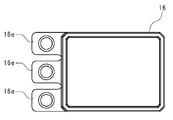
- the upper packing 16 forms two tongue-like pieces 16e from one of the substantially square pillar-shaped side walls, but three or more tongue-like pieces 16e are provided as long as they are provided at intervals. May be provided (three in FIG. 7).
- the interval can be freely set, and the interval can be different.
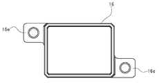
- How to arrange the plurality of tongue-like pieces 16e is not particularly limited. It is not always necessary to project only from one side wall, and for example, it may project from the opposite side wall as shown in FIG. In FIG. 8, each tongue-like piece 16e is arranged at a diagonal position, so that the anti-rotation effect is more effectively exhibited.
- the tongue-like piece 16e as the protruding portion has a substantially square shape.
- a protruding portion having a different shape such as a handy shape or an elliptical shape may be employed.
- the external terminals 14 and 15 are provided on the lid 4, but the external terminals 14 and 15 can be provided on the battery container 2 instead of the lid 4.
- the upper packing 16 is stopped by caulking and joining each protrusion 4c to a pair of tongue-like pieces (projections) 16e, 16e.
- a pair of tongue-like pieces (projections) 16e, 16e may be provided, and the mounting recess 16c that engages with the engagement receiving portion 11 may have a rotation-stopping effect.
- the cross-sectional shape (including size) of the protrusion 4c is the same shape on the positive electrode side and the negative electrode side, but it is preferable to make them different.
- the cross-sectional shape of the protrusion 4c is made to be different from a square and a circle on the positive electrode side and the negative electrode side (in FIG. 10, the upper end portion of the protrusion 4c is caulked and deformed into a circle.
- the dotted line portion is the original shape and the shape of the insertion hole 16f.
- If the tongue-like piece 16e of the upper packing 16 is formed with an insertion hole 16f having a cross-sectional shape corresponding to this shape. Good. According to this, it is possible to reliably prevent the upper packing 16 and the external terminals 14 and 15 from being attached by mistake on the positive electrode side and the negative electrode side.
- the formation position of the protrusion 4c may be different between the positive electrode side and the negative electrode side.
- the formation position of the protrusion 4c may be on both sides of the engagement receiving portion 11, and the position in the width direction may be different between the positive electrode side and the negative electrode side.
- each engagement receiving portion 11 on the positive electrode side and the negative electrode side of the lid body 4 is made different between the positive electrode side and the negative electrode side
- the shape of the mounting recess 16c of each upper packing 16 to be mounted may be a shape matching this.
- each engagement receiving portion 11 has the same substantially rectangular shape in plan view, but one end side of one engagement receiving portion 11 has a substantially arc shape in plan view. What is necessary is just to make the recessed part 16c for mounting
- the configuration of the upper packing 16 has been described.
- the upper packing 16 can also be used for the lower packing interposed between the external terminals 14 and 15 and the battery case 2.
Landscapes
- Chemical & Material Sciences (AREA)
- Chemical Kinetics & Catalysis (AREA)
- Electrochemistry (AREA)
- General Chemical & Material Sciences (AREA)
- Engineering & Computer Science (AREA)
- Manufacturing & Machinery (AREA)
- Connection Of Batteries Or Terminals (AREA)
- Sealing Battery Cases Or Jackets (AREA)
Abstract
Description
外装体と、外装体から外部に露出する露出面を有する外部端子と、外装体の内部に配置され、外部端子に接続される集電体と、外装体の内部に配置され、集電体に接続される電極体と、を備えた蓄電素子であって、
前記外装体は、外方に向かって突出する複数の突起を備え、
前記外部端子と前記外装体の間に介在する本体と、本体からそれぞれ延び、前記外装体の各突起が挿通する挿通孔を形成された複数の突出部とを有するパッキンを、さらに備え、
前記各突起は、前記各突出部の挿通孔にそれぞれ挿通された後、前記外装体に対してかしめ接合されている構成としたものである。
前記外装体の突起は、前記各突出部に配置可能な複数で構成するようにしてもよい。
前記外装体の突起は、前記各突出部に配置可能な複数で構成するようにしてもよい。
前記外装体の突起は、正極側と負極側とで形状を相違させ、
前記正極側と前記負極側とにそれぞれ配置されるパッキンの突出部に形成した挿通孔は、対応する各極性の突起のみが挿通可能な形状であるのが好ましい。
前記外装体の突起は、正極側と負極側とで位置をずらせるようにしてもよい。
外装体と、外装体から外部に露出する露出面を有する外部端子と、外装体の内部に配置され、外部端子に接続される集電体と、外装体の内部に配置され、集電体に接続される電極体と、を備えた蓄電素子であって、
前記外部端子は、正極端子と負極端子とからなり、
前記外装体は、外方に向かって膨出する一対の膨出部と、各膨出部の近傍に形成され、外方に向かって突出する突起とをそれぞれ形成され、
前記外部端子と前記外装体の間に介在する本体と、本体からそれぞれ延び、前記外装体の突起が挿通する挿通孔を形成された突出部とを有するパッキンを、さらに備え、
前記突起は、前記突出部の挿通孔に挿通された後、前記外装体に対してかしめ接合されている構成としたものである。
2 電池容器
3 電極体
4 蓋体
4a 下面
4b 上面
4c 突起
8 安全弁
9 注液孔
10 クリップ
11 係合受部
11a 係合凹部
11b 貫通孔
12 負極集電体
12a 基部
12b 脚部
12c 貫通孔
13 正極集電体
13a 基部
13b 脚部
13c 貫通孔
14 負極外部端子
15 正極外部端子
15a 板状体
15b 軸部
15c カシメ頭部
16 上パッキン
16a 隔壁
16b 端子保持凹部
16c 装着用凹部
16d 筒状部
16e 舌状部
16f 挿通孔
17 負極下パッキン
17a 被カシメ部
17b 平坦部
17c 貫通孔
18 正極下パッキン
18a 貫通孔
21 板状体
21a 貫通孔
22 リベット
22a 顎部
22b 軸部
22c カシメ頭部
t 間隔
Claims (9)
- 外装体と、外装体から外部に露出する露出面を有する外部端子と、外装体の内部に配置され、外部端子に接続される集電体と、外装体の内部に配置され、集電体に接続される電極体と、を備えた蓄電素子であって、
前記外装体は、外方に向かって突出する複数の突起を備え、
前記外部端子と前記外装体の間に介在する本体と、本体からそれぞれ延び、前記外装体の各突起が挿通する挿通孔を形成された複数の突出部とを有するパッキンを、さらに備え、
前記各突起は、前記各突出部の挿通孔にそれぞれ挿通された後、前記外装体に対してかしめ接合されていることを特徴とする蓄電素子。 - 前記パッキンの突出部は、間隔を空けて隣接して配置される複数で構成され、
前記外装体の突起は、前記各突出部に配置可能な複数で構成したことを特徴とする請求項1に記載の蓄電素子。 - 前記パッキンの突出部は、本体を挟んで少なくとも1つが反対側に配置される複数で構成され、
前記外装体の突起は、前記各突出部に配置可能な複数で構成したことを特徴とする請求項1に記載の蓄電素子。 - 前記外装体の突起は、外装体に別部材を一体化したものであることを特徴とする請求項1から3のいずれか1項に記載の蓄電素子。
- 前記外装体の突起は、外装体の一部を突出させてなる構成であることを特徴とする請求項1から3のいずれか1項に記載の蓄電素子。
- 前記外部端子は、正極端子と負極端子とからなり、
前記外装体の突起は、正極側と負極側とで形状を相違させ、
前記正極側と前記負極側とにそれぞれ配置されるパッキンの突出部に形成した挿通孔は、対応する各極性の突起のみが挿通可能な形状であることを特徴とする請求項1から5のいずれか1項に記載の蓄電素子。 - 前記外部端子は、正極端子と負極端子とからなり、
前記外装体の突起は、正極側と負極側とで位置をずらせたことを特徴とする請求項1から5のいずれか1項に記載の蓄電素子。 - 外装体と、外装体から外部に露出する露出面を有する外部端子と、外装体の内部に配置され、外部端子に接続される集電体と、外装体の内部に配置され、集電体に接続される電極体と、を備えた蓄電素子であって、
前記外部端子は、正極端子と負極端子とからなり、
前記外装体は、外方に向かって膨出する一対の膨出部と、各膨出部の近傍に形成され、外方に向かって突出する突起とをそれぞれ形成され、
前記外部端子と前記外装体の間に介在する本体と、本体からそれぞれ延び、前記外装体の突起が挿通する挿通孔を形成された突出部とを有するパッキンを、さらに備え、
前記突起は、前記突出部の挿通孔に挿通された後、前記外装体に対してかしめ接合されていることを特徴とする蓄電素子。 - 前記外装体の膨出部は、正極側と負極側とで形状が相違することを特徴とする請求項8に記載の蓄電素子。
Priority Applications (5)
| Application Number | Priority Date | Filing Date | Title |
|---|---|---|---|
| US13/982,741 US9209439B2 (en) | 2011-01-31 | 2012-01-30 | Electric storage device |
| JP2012555859A JP6011344B2 (ja) | 2011-01-31 | 2012-01-30 | 蓄電素子 |
| DE112012000626.7T DE112012000626B4 (de) | 2011-01-31 | 2012-01-30 | Elektrisches Speichergerät |
| CN201280005555.4A CN103329303B (zh) | 2011-01-31 | 2012-01-30 | 蓄电元件 |
| KR1020137018624A KR101912963B1 (ko) | 2011-01-31 | 2012-01-30 | 축전 소자 |
Applications Claiming Priority (2)
| Application Number | Priority Date | Filing Date | Title |
|---|---|---|---|
| JP2011-018541 | 2011-01-31 | ||
| JP2011018541 | 2011-01-31 |
Publications (1)
| Publication Number | Publication Date |
|---|---|
| WO2012105491A1 true WO2012105491A1 (ja) | 2012-08-09 |
Family
ID=46602705
Family Applications (1)
| Application Number | Title | Priority Date | Filing Date |
|---|---|---|---|
| PCT/JP2012/051979 Ceased WO2012105491A1 (ja) | 2011-01-31 | 2012-01-30 | 蓄電素子 |
Country Status (6)
| Country | Link |
|---|---|
| US (1) | US9209439B2 (ja) |
| JP (2) | JP6011344B2 (ja) |
| KR (1) | KR101912963B1 (ja) |
| CN (1) | CN103329303B (ja) |
| DE (1) | DE112012000626B4 (ja) |
| WO (1) | WO2012105491A1 (ja) |
Cited By (5)
| Publication number | Priority date | Publication date | Assignee | Title |
|---|---|---|---|---|
| WO2014103874A1 (ja) * | 2012-12-25 | 2014-07-03 | 株式会社Gsユアサ | 蓄電素子、蓄電素子アセンブリ及び蓄電素子の製造方法 |
| WO2015119027A1 (ja) * | 2014-02-05 | 2015-08-13 | 住友電気工業株式会社 | 蓄電デバイス |
| JP2015198080A (ja) * | 2014-03-31 | 2015-11-09 | 三星エスディアイ株式会社Samsung SDI Co.,Ltd. | 二次電池 |
| JP2016122604A (ja) * | 2014-12-25 | 2016-07-07 | 株式会社Gsユアサ | 蓄電素子 |
| US9537133B2 (en) | 2012-07-30 | 2017-01-03 | Gs Yuasa International Ltd | Electric storage device and power source module |
Families Citing this family (8)
| Publication number | Priority date | Publication date | Assignee | Title |
|---|---|---|---|---|
| KR102368086B1 (ko) | 2015-03-16 | 2022-02-24 | 삼성에스디아이 주식회사 | 이차 전지 |
| JP6701211B2 (ja) * | 2015-09-18 | 2020-05-27 | ロベルト・ボッシュ・ゲゼルシャフト・ミト・ベシュレンクテル・ハフツングRobert Bosch Gmbh | 蓄電素子及び蓄電素子の製造方法 |
| CN108701804A (zh) * | 2016-02-19 | 2018-10-23 | 株式会社杰士汤浅国际 | 蓄电元件以及蓄电元件的制造方法 |
| CN107808946A (zh) * | 2016-09-08 | 2018-03-16 | 株式会社杰士汤浅国际 | 蓄电元件 |
| JP6947575B2 (ja) * | 2017-07-31 | 2021-10-13 | 株式会社Gsユアサ | 蓄電素子の製造方法 |
| IL302072A (en) * | 2020-11-03 | 2023-06-01 | Eaglepicher Technologies Llc | Terminal assemblies and methods of using and making the same |
| KR20240149504A (ko) * | 2023-04-06 | 2024-10-15 | 에스케이온 주식회사 | 배터리 셀 |
| JP7778109B2 (ja) * | 2023-06-07 | 2025-12-01 | プライムプラネットエナジー&ソリューションズ株式会社 | 密閉型二次電池の製造方法 |
Citations (2)
| Publication number | Priority date | Publication date | Assignee | Title |
|---|---|---|---|---|
| JP2009283335A (ja) * | 2008-05-23 | 2009-12-03 | Gs Yuasa Corporation | 電池 |
| JP2009289611A (ja) * | 2008-05-29 | 2009-12-10 | Toyota Motor Corp | 電池、車両及び電池搭載機器 |
Family Cites Families (14)
| Publication number | Priority date | Publication date | Assignee | Title |
|---|---|---|---|---|
| JP3787873B2 (ja) | 1995-11-24 | 2006-06-21 | 株式会社ジーエス・ユアサコーポレーション | 電池 |
| JP3593918B2 (ja) | 1999-04-27 | 2004-11-24 | 新神戸電機株式会社 | 非水電解液電池 |
| US6579640B1 (en) | 1999-09-28 | 2003-06-17 | Sanyo Electric Co., Ltd. | Sealed rectangular battery and manufacturing method for the same |
| JP3749048B2 (ja) | 1999-09-28 | 2006-02-22 | 三洋電機株式会社 | 角形密閉電池とその製造方法 |
| JP4247595B2 (ja) | 2002-05-30 | 2009-04-02 | 株式会社ジーエス・ユアサコーポレーション | 電池 |
| US7601460B2 (en) * | 2003-11-28 | 2009-10-13 | Panasonic Corporation | Prismatic battery and manufacturing method thereof |
| JP2005259388A (ja) | 2004-03-09 | 2005-09-22 | Asada Kinzoku Kogyo Kk | 電池容器とその製造方法及び電池 |
| JP2005339990A (ja) * | 2004-05-27 | 2005-12-08 | Toyota Motor Corp | 密閉型電池及び密閉型電池の製造方法 |
| JP4584092B2 (ja) | 2005-09-20 | 2010-11-17 | 矢崎総業株式会社 | バッテリーターミナル |
| JP2009259451A (ja) * | 2008-04-14 | 2009-11-05 | Toyota Motor Corp | 密閉型電池 |
| JP5418809B2 (ja) | 2008-10-16 | 2014-02-19 | 株式会社Gsユアサ | 電池及びその製造方法 |
| JP4756392B2 (ja) * | 2008-11-27 | 2011-08-24 | トヨタ自動車株式会社 | 電池 |
| JP4858726B2 (ja) * | 2009-01-07 | 2012-01-18 | 三菱自動車工業株式会社 | 二次電池の保持構造 |
| US8748034B2 (en) | 2011-04-14 | 2014-06-10 | Gs Yuasa International Ltd. | Battery including baffling member including one of projecting portion and recessed portion extending from lid plate |
-
2012
- 2012-01-30 CN CN201280005555.4A patent/CN103329303B/zh active Active
- 2012-01-30 WO PCT/JP2012/051979 patent/WO2012105491A1/ja not_active Ceased
- 2012-01-30 JP JP2012555859A patent/JP6011344B2/ja active Active
- 2012-01-30 US US13/982,741 patent/US9209439B2/en active Active
- 2012-01-30 KR KR1020137018624A patent/KR101912963B1/ko active Active
- 2012-01-30 DE DE112012000626.7T patent/DE112012000626B4/de active Active
-
2016
- 2016-02-19 JP JP2016030317A patent/JP6241486B2/ja active Active
Patent Citations (2)
| Publication number | Priority date | Publication date | Assignee | Title |
|---|---|---|---|---|
| JP2009283335A (ja) * | 2008-05-23 | 2009-12-03 | Gs Yuasa Corporation | 電池 |
| JP2009289611A (ja) * | 2008-05-29 | 2009-12-10 | Toyota Motor Corp | 電池、車両及び電池搭載機器 |
Cited By (9)
| Publication number | Priority date | Publication date | Assignee | Title |
|---|---|---|---|---|
| US9537133B2 (en) | 2012-07-30 | 2017-01-03 | Gs Yuasa International Ltd | Electric storage device and power source module |
| WO2014103874A1 (ja) * | 2012-12-25 | 2014-07-03 | 株式会社Gsユアサ | 蓄電素子、蓄電素子アセンブリ及び蓄電素子の製造方法 |
| CN104904036A (zh) * | 2012-12-25 | 2015-09-09 | 株式会社杰士汤浅国际 | 蓄电元件、蓄电元件组件以及蓄电元件的制造方法 |
| JPWO2014103874A1 (ja) * | 2012-12-25 | 2017-01-12 | 株式会社Gsユアサ | 蓄電素子、蓄電素子アセンブリ及び蓄電素子の製造方法 |
| US10135040B2 (en) | 2012-12-25 | 2018-11-20 | Gs Yuasa International Ltd. | Electric storage device, electric storage device assembly, and method for producing electric storage device |
| CN104904036B (zh) * | 2012-12-25 | 2019-05-28 | 株式会社杰士汤浅国际 | 蓄电元件、蓄电元件组件以及蓄电元件的制造方法 |
| WO2015119027A1 (ja) * | 2014-02-05 | 2015-08-13 | 住友電気工業株式会社 | 蓄電デバイス |
| JP2015198080A (ja) * | 2014-03-31 | 2015-11-09 | 三星エスディアイ株式会社Samsung SDI Co.,Ltd. | 二次電池 |
| JP2016122604A (ja) * | 2014-12-25 | 2016-07-07 | 株式会社Gsユアサ | 蓄電素子 |
Also Published As
| Publication number | Publication date |
|---|---|
| JP6241486B2 (ja) | 2017-12-06 |
| US20130309559A1 (en) | 2013-11-21 |
| JP2016085997A (ja) | 2016-05-19 |
| DE112012000626T5 (de) | 2013-11-14 |
| KR20140004125A (ko) | 2014-01-10 |
| CN103329303B (zh) | 2016-05-11 |
| JP6011344B2 (ja) | 2016-10-19 |
| CN103329303A (zh) | 2013-09-25 |
| KR101912963B1 (ko) | 2018-10-29 |
| JPWO2012105491A1 (ja) | 2014-07-03 |
| US9209439B2 (en) | 2015-12-08 |
| DE112012000626B4 (de) | 2023-12-07 |
Similar Documents
| Publication | Publication Date | Title |
|---|---|---|
| JP6241486B2 (ja) | 蓄電素子 | |
| EP2463933B1 (en) | Battery | |
| KR101921157B1 (ko) | 축전 소자, 및 단자의 제조 방법 | |
| JP5987465B2 (ja) | 蓄電素子及びその製造方法 | |
| JP5742260B2 (ja) | 電池 | |
| JP5625959B2 (ja) | 電池 | |
| JPWO2016093338A1 (ja) | 蓄電素子 | |
| JPWO2016159099A1 (ja) | 蓄電素子 | |
| US11165114B2 (en) | Energy storage device | |
| JP6693042B2 (ja) | 蓄電素子 | |
| WO2017115856A1 (ja) | 封止部材、蓄電素子及び蓄電素子の製造方法 | |
| JP2011216402A (ja) | 角形二次電池 | |
| JP2018535507A (ja) | 蓄電素子 | |
| JP2009231141A (ja) | 電池モジュール | |
| JP6213036B2 (ja) | 蓄電素子及びその製造方法 | |
| JP2013131396A (ja) | 蓄電素子 | |
| JP2015005479A (ja) | 蓄電素子 | |
| JP6032302B2 (ja) | 電池 | |
| JP5761055B2 (ja) | 電池 | |
| JP2014011081A (ja) | リチウムイオン二次電池の電極端子構造 | |
| JP2014011080A (ja) | リチウムイオン二次電池の電極端子構造 | |
| JP2005353472A (ja) | リブ付き電池缶および密閉型二次電池 | |
| JP2018041646A (ja) | 蓄電素子及び蓄電素子の製造方法 |
Legal Events
| Date | Code | Title | Description |
|---|---|---|---|
| WWE | Wipo information: entry into national phase |
Ref document number: 201280005555.4 Country of ref document: CN |
|
| 121 | Ep: the epo has been informed by wipo that ep was designated in this application |
Ref document number: 12742745 Country of ref document: EP Kind code of ref document: A1 |
|
| ENP | Entry into the national phase |
Ref document number: 2012555859 Country of ref document: JP Kind code of ref document: A |
|
| ENP | Entry into the national phase |
Ref document number: 20137018624 Country of ref document: KR Kind code of ref document: A |
|
| WWE | Wipo information: entry into national phase |
Ref document number: 13982741 Country of ref document: US |
|
| WWE | Wipo information: entry into national phase |
Ref document number: 112012000626 Country of ref document: DE Ref document number: 1120120006267 Country of ref document: DE |
|
| 122 | Ep: pct application non-entry in european phase |
Ref document number: 12742745 Country of ref document: EP Kind code of ref document: A1 |