WO2015119027A1 - 蓄電デバイス - Google Patents
蓄電デバイス Download PDFInfo
- Publication number
- WO2015119027A1 WO2015119027A1 PCT/JP2015/052439 JP2015052439W WO2015119027A1 WO 2015119027 A1 WO2015119027 A1 WO 2015119027A1 JP 2015052439 W JP2015052439 W JP 2015052439W WO 2015119027 A1 WO2015119027 A1 WO 2015119027A1
- Authority
- WO
- WIPO (PCT)
- Prior art keywords
- wall
- storage device
- positive electrode
- negative electrode
- housing case
- Prior art date
Links
- 230000005611 electricity Effects 0.000 claims description 47
- 230000004048 modification Effects 0.000 description 10
- 238000012986 modification Methods 0.000 description 10
- HBBGRARXTFLTSG-UHFFFAOYSA-N Lithium ion Chemical compound [Li+] HBBGRARXTFLTSG-UHFFFAOYSA-N 0.000 description 5
- 229910001416 lithium ion Inorganic materials 0.000 description 5
- 239000003990 capacitor Substances 0.000 description 4
- 239000000463 material Substances 0.000 description 4
- 229910052751 metal Inorganic materials 0.000 description 3
- 239000002184 metal Substances 0.000 description 3
- 238000007789 sealing Methods 0.000 description 3
- 125000006850 spacer group Chemical group 0.000 description 3
- 230000004308 accommodation Effects 0.000 description 2
- 229910052782 aluminium Inorganic materials 0.000 description 2
- XAGFODPZIPBFFR-UHFFFAOYSA-N aluminium Chemical compound [Al] XAGFODPZIPBFFR-UHFFFAOYSA-N 0.000 description 2
- 238000005516 engineering process Methods 0.000 description 2
- 238000000034 method Methods 0.000 description 2
- 229910045601 alloy Inorganic materials 0.000 description 1
- 239000000956 alloy Substances 0.000 description 1
- 238000005452 bending Methods 0.000 description 1
- 239000011195 cermet Substances 0.000 description 1
- 239000000470 constituent Substances 0.000 description 1
- 238000005260 corrosion Methods 0.000 description 1
- 230000007797 corrosion Effects 0.000 description 1
- 238000002788 crimping Methods 0.000 description 1
- 239000003792 electrolyte Substances 0.000 description 1
- 239000008151 electrolyte solution Substances 0.000 description 1
- 238000002347 injection Methods 0.000 description 1
- 239000007924 injection Substances 0.000 description 1
- 239000011347 resin Substances 0.000 description 1
- 229920005989 resin Polymers 0.000 description 1
- 239000010935 stainless steel Substances 0.000 description 1
- 229910001220 stainless steel Inorganic materials 0.000 description 1
- 230000009466 transformation Effects 0.000 description 1
Images


Classifications
-
- H—ELECTRICITY
- H01—ELECTRIC ELEMENTS
- H01G—CAPACITORS; CAPACITORS, RECTIFIERS, DETECTORS, SWITCHING DEVICES, LIGHT-SENSITIVE OR TEMPERATURE-SENSITIVE DEVICES OF THE ELECTROLYTIC TYPE
- H01G11/00—Hybrid capacitors, i.e. capacitors having different positive and negative electrodes; Electric double-layer [EDL] capacitors; Processes for the manufacture thereof or of parts thereof
- H01G11/74—Terminals, e.g. extensions of current collectors
- H01G11/76—Terminals, e.g. extensions of current collectors specially adapted for integration in multiple or stacked hybrid or EDL capacitors
-
- H—ELECTRICITY
- H01—ELECTRIC ELEMENTS
- H01G—CAPACITORS; CAPACITORS, RECTIFIERS, DETECTORS, SWITCHING DEVICES, LIGHT-SENSITIVE OR TEMPERATURE-SENSITIVE DEVICES OF THE ELECTROLYTIC TYPE
- H01G11/00—Hybrid capacitors, i.e. capacitors having different positive and negative electrodes; Electric double-layer [EDL] capacitors; Processes for the manufacture thereof or of parts thereof
- H01G11/04—Hybrid capacitors
- H01G11/06—Hybrid capacitors with one of the electrodes allowing ions to be reversibly doped thereinto, e.g. lithium ion capacitors [LIC]
-
- H—ELECTRICITY
- H01—ELECTRIC ELEMENTS
- H01G—CAPACITORS; CAPACITORS, RECTIFIERS, DETECTORS, SWITCHING DEVICES, LIGHT-SENSITIVE OR TEMPERATURE-SENSITIVE DEVICES OF THE ELECTROLYTIC TYPE
- H01G11/00—Hybrid capacitors, i.e. capacitors having different positive and negative electrodes; Electric double-layer [EDL] capacitors; Processes for the manufacture thereof or of parts thereof
- H01G11/22—Electrodes
- H01G11/26—Electrodes characterised by their structure, e.g. multi-layered, porosity or surface features
-
- H—ELECTRICITY
- H01—ELECTRIC ELEMENTS
- H01G—CAPACITORS; CAPACITORS, RECTIFIERS, DETECTORS, SWITCHING DEVICES, LIGHT-SENSITIVE OR TEMPERATURE-SENSITIVE DEVICES OF THE ELECTROLYTIC TYPE
- H01G11/00—Hybrid capacitors, i.e. capacitors having different positive and negative electrodes; Electric double-layer [EDL] capacitors; Processes for the manufacture thereof or of parts thereof
- H01G11/52—Separators
-
- H—ELECTRICITY
- H01—ELECTRIC ELEMENTS
- H01G—CAPACITORS; CAPACITORS, RECTIFIERS, DETECTORS, SWITCHING DEVICES, LIGHT-SENSITIVE OR TEMPERATURE-SENSITIVE DEVICES OF THE ELECTROLYTIC TYPE
- H01G11/00—Hybrid capacitors, i.e. capacitors having different positive and negative electrodes; Electric double-layer [EDL] capacitors; Processes for the manufacture thereof or of parts thereof
- H01G11/74—Terminals, e.g. extensions of current collectors
-
- H—ELECTRICITY
- H01—ELECTRIC ELEMENTS
- H01G—CAPACITORS; CAPACITORS, RECTIFIERS, DETECTORS, SWITCHING DEVICES, LIGHT-SENSITIVE OR TEMPERATURE-SENSITIVE DEVICES OF THE ELECTROLYTIC TYPE
- H01G11/00—Hybrid capacitors, i.e. capacitors having different positive and negative electrodes; Electric double-layer [EDL] capacitors; Processes for the manufacture thereof or of parts thereof
- H01G11/78—Cases; Housings; Encapsulations; Mountings
- H01G11/80—Gaskets; Sealings
-
- H—ELECTRICITY
- H01—ELECTRIC ELEMENTS
- H01M—PROCESSES OR MEANS, e.g. BATTERIES, FOR THE DIRECT CONVERSION OF CHEMICAL ENERGY INTO ELECTRICAL ENERGY
- H01M10/00—Secondary cells; Manufacture thereof
- H01M10/04—Construction or manufacture in general
- H01M10/0413—Large-sized flat cells or batteries for motive or stationary systems with plate-like electrodes
-
- H—ELECTRICITY
- H01—ELECTRIC ELEMENTS
- H01M—PROCESSES OR MEANS, e.g. BATTERIES, FOR THE DIRECT CONVERSION OF CHEMICAL ENERGY INTO ELECTRICAL ENERGY
- H01M10/00—Secondary cells; Manufacture thereof
- H01M10/05—Accumulators with non-aqueous electrolyte
- H01M10/052—Li-accumulators
- H01M10/0525—Rocking-chair batteries, i.e. batteries with lithium insertion or intercalation in both electrodes; Lithium-ion batteries
-
- H—ELECTRICITY
- H01—ELECTRIC ELEMENTS
- H01M—PROCESSES OR MEANS, e.g. BATTERIES, FOR THE DIRECT CONVERSION OF CHEMICAL ENERGY INTO ELECTRICAL ENERGY
- H01M10/00—Secondary cells; Manufacture thereof
- H01M10/05—Accumulators with non-aqueous electrolyte
- H01M10/058—Construction or manufacture
-
- H—ELECTRICITY
- H01—ELECTRIC ELEMENTS
- H01M—PROCESSES OR MEANS, e.g. BATTERIES, FOR THE DIRECT CONVERSION OF CHEMICAL ENERGY INTO ELECTRICAL ENERGY
- H01M50/00—Constructional details or processes of manufacture of the non-active parts of electrochemical cells other than fuel cells, e.g. hybrid cells
- H01M50/10—Primary casings; Jackets or wrappings
- H01M50/102—Primary casings; Jackets or wrappings characterised by their shape or physical structure
- H01M50/103—Primary casings; Jackets or wrappings characterised by their shape or physical structure prismatic or rectangular
-
- H—ELECTRICITY
- H01—ELECTRIC ELEMENTS
- H01M—PROCESSES OR MEANS, e.g. BATTERIES, FOR THE DIRECT CONVERSION OF CHEMICAL ENERGY INTO ELECTRICAL ENERGY
- H01M50/00—Constructional details or processes of manufacture of the non-active parts of electrochemical cells other than fuel cells, e.g. hybrid cells
- H01M50/10—Primary casings; Jackets or wrappings
- H01M50/147—Lids or covers
-
- H—ELECTRICITY
- H01—ELECTRIC ELEMENTS
- H01M—PROCESSES OR MEANS, e.g. BATTERIES, FOR THE DIRECT CONVERSION OF CHEMICAL ENERGY INTO ELECTRICAL ENERGY
- H01M50/00—Constructional details or processes of manufacture of the non-active parts of electrochemical cells other than fuel cells, e.g. hybrid cells
- H01M50/10—Primary casings; Jackets or wrappings
- H01M50/172—Arrangements of electric connectors penetrating the casing
- H01M50/174—Arrangements of electric connectors penetrating the casing adapted for the shape of the cells
- H01M50/176—Arrangements of electric connectors penetrating the casing adapted for the shape of the cells for prismatic or rectangular cells
-
- H—ELECTRICITY
- H01—ELECTRIC ELEMENTS
- H01M—PROCESSES OR MEANS, e.g. BATTERIES, FOR THE DIRECT CONVERSION OF CHEMICAL ENERGY INTO ELECTRICAL ENERGY
- H01M50/00—Constructional details or processes of manufacture of the non-active parts of electrochemical cells other than fuel cells, e.g. hybrid cells
- H01M50/50—Current conducting connections for cells or batteries
- H01M50/531—Electrode connections inside a battery casing
- H01M50/54—Connection of several leads or tabs of plate-like electrode stacks, e.g. electrode pole straps or bridges
-
- H—ELECTRICITY
- H01—ELECTRIC ELEMENTS
- H01M—PROCESSES OR MEANS, e.g. BATTERIES, FOR THE DIRECT CONVERSION OF CHEMICAL ENERGY INTO ELECTRICAL ENERGY
- H01M50/00—Constructional details or processes of manufacture of the non-active parts of electrochemical cells other than fuel cells, e.g. hybrid cells
- H01M50/50—Current conducting connections for cells or batteries
- H01M50/543—Terminals
- H01M50/547—Terminals characterised by the disposition of the terminals on the cells
- H01M50/55—Terminals characterised by the disposition of the terminals on the cells on the same side of the cell
-
- H—ELECTRICITY
- H01—ELECTRIC ELEMENTS
- H01M—PROCESSES OR MEANS, e.g. BATTERIES, FOR THE DIRECT CONVERSION OF CHEMICAL ENERGY INTO ELECTRICAL ENERGY
- H01M50/00—Constructional details or processes of manufacture of the non-active parts of electrochemical cells other than fuel cells, e.g. hybrid cells
- H01M50/50—Current conducting connections for cells or batteries
- H01M50/543—Terminals
- H01M50/552—Terminals characterised by their shape
- H01M50/553—Terminals adapted for prismatic, pouch or rectangular cells
-
- H—ELECTRICITY
- H01—ELECTRIC ELEMENTS
- H01M—PROCESSES OR MEANS, e.g. BATTERIES, FOR THE DIRECT CONVERSION OF CHEMICAL ENERGY INTO ELECTRICAL ENERGY
- H01M50/00—Constructional details or processes of manufacture of the non-active parts of electrochemical cells other than fuel cells, e.g. hybrid cells
- H01M50/50—Current conducting connections for cells or batteries
- H01M50/543—Terminals
- H01M50/564—Terminals characterised by their manufacturing process
- H01M50/567—Terminals characterised by their manufacturing process by fixing means, e.g. screws, rivets or bolts
-
- H—ELECTRICITY
- H01—ELECTRIC ELEMENTS
- H01M—PROCESSES OR MEANS, e.g. BATTERIES, FOR THE DIRECT CONVERSION OF CHEMICAL ENERGY INTO ELECTRICAL ENERGY
- H01M2220/00—Batteries for particular applications
- H01M2220/10—Batteries in stationary systems, e.g. emergency power source in plant
-
- Y—GENERAL TAGGING OF NEW TECHNOLOGICAL DEVELOPMENTS; GENERAL TAGGING OF CROSS-SECTIONAL TECHNOLOGIES SPANNING OVER SEVERAL SECTIONS OF THE IPC; TECHNICAL SUBJECTS COVERED BY FORMER USPC CROSS-REFERENCE ART COLLECTIONS [XRACs] AND DIGESTS
- Y02—TECHNOLOGIES OR APPLICATIONS FOR MITIGATION OR ADAPTATION AGAINST CLIMATE CHANGE
- Y02E—REDUCTION OF GREENHOUSE GAS [GHG] EMISSIONS, RELATED TO ENERGY GENERATION, TRANSMISSION OR DISTRIBUTION
- Y02E60/00—Enabling technologies; Technologies with a potential or indirect contribution to GHG emissions mitigation
- Y02E60/10—Energy storage using batteries
-
- Y—GENERAL TAGGING OF NEW TECHNOLOGICAL DEVELOPMENTS; GENERAL TAGGING OF CROSS-SECTIONAL TECHNOLOGIES SPANNING OVER SEVERAL SECTIONS OF THE IPC; TECHNICAL SUBJECTS COVERED BY FORMER USPC CROSS-REFERENCE ART COLLECTIONS [XRACs] AND DIGESTS
- Y02—TECHNOLOGIES OR APPLICATIONS FOR MITIGATION OR ADAPTATION AGAINST CLIMATE CHANGE
- Y02E—REDUCTION OF GREENHOUSE GAS [GHG] EMISSIONS, RELATED TO ENERGY GENERATION, TRANSMISSION OR DISTRIBUTION
- Y02E60/00—Enabling technologies; Technologies with a potential or indirect contribution to GHG emissions mitigation
- Y02E60/13—Energy storage using capacitors
-
- Y—GENERAL TAGGING OF NEW TECHNOLOGICAL DEVELOPMENTS; GENERAL TAGGING OF CROSS-SECTIONAL TECHNOLOGIES SPANNING OVER SEVERAL SECTIONS OF THE IPC; TECHNICAL SUBJECTS COVERED BY FORMER USPC CROSS-REFERENCE ART COLLECTIONS [XRACs] AND DIGESTS
- Y02—TECHNOLOGIES OR APPLICATIONS FOR MITIGATION OR ADAPTATION AGAINST CLIMATE CHANGE
- Y02P—CLIMATE CHANGE MITIGATION TECHNOLOGIES IN THE PRODUCTION OR PROCESSING OF GOODS
- Y02P70/00—Climate change mitigation technologies in the production process for final industrial or consumer products
- Y02P70/50—Manufacturing or production processes characterised by the final manufactured product
Definitions
- the present invention relates to an electricity storage device such as a lithium ion capacitor or a lithium ion battery.
- a storage case is composed of a bottomed cylindrical outer can and a flat sealing plate that seals an opening of the outer can, and most of the storage case has a rectangular parallelepiped shape (for example, , See Patent Document 1). And the electrode group was accommodated in such an accommodation case. Moreover, the external terminal was provided in the sealing board.
- a positive electrode tab provided on each of the positive electrode plates and a negative electrode tab provided on each of the negative electrode plates protrude from the end face of the electrode group directed toward the sealing plate.
- the electrode group and the external terminal are electrically connected through these tabs.
- the space factor of the electrode group is about 85 to 90% even at the highest, and there is a limit to the improvement of the space factor. . Therefore, the volume energy density calculated
- an object of the present invention is to provide a power storage device having a remarkably high volumetric energy density as compared with conventional power storage devices.
- One aspect of the present invention is an electrode group in which a plurality of positive electrode plates and a plurality of negative electrode plates are stacked with a separator interposed therebetween, a storage case in which the electrode group is stored, a storage case, and an electrical connection to the electrode group And an external terminal connected to the battery.
- the storage case is provided with a first main wall and a second main wall facing each other, a first side wall and a second side wall connecting the first main wall and the second main wall on the left and right sides, and an external terminal. It consists of a top wall and a bottom wall.
- the electrode group is housed in the housing case with both end surfaces in the stacking direction of the positive electrode plate and the negative electrode plate facing the inner surface of the first main wall and the inner surface of the second main wall, respectively. From the end surface of the electrode group directed toward the top wall, a plurality of positive electrode tabs respectively provided closer to the first side wall with respect to the plurality of positive electrode plates, and closer to the second side wall with respect to the plurality of negative electrode plates, respectively. A plurality of provided negative electrode tabs protrude. A recess that is recessed to a position between the positive electrode tab and the negative electrode tab is formed on the top wall of the housing case.
- the volume energy density is significantly higher than that of the conventional power storage device.
- FIG. 4 is a cross-sectional end view of the electricity storage device along line IV-IV shown in FIG. 3. It is a principal part enlarged view of the cross section along the VV line
- An electricity storage device includes an electrode group in which a plurality of positive electrode plates and a plurality of negative electrode plates are stacked via a separator, a storage case in which the electrode group is stored, a storage case, and an electrode And an external terminal electrically connected to the group.
- the storage case is provided with a first main wall and a second main wall facing each other, a first side wall and a second side wall connecting the first main wall and the second main wall on the left and right sides, and an external terminal. It consists of a top wall and a bottom wall.
- the electrode group is housed in the housing case with both end surfaces in the stacking direction of the positive electrode plate and the negative electrode plate facing the inner surface of the first main wall and the inner surface of the second main wall, respectively. From the end surface of the electrode group directed toward the top wall, a plurality of positive electrode tabs respectively provided closer to the first side wall with respect to the plurality of positive electrode plates, and closer to the second side wall with respect to the plurality of negative electrode plates, respectively. A plurality of provided negative electrode tabs protrude. A recess that is recessed to a position between the positive electrode tab and the negative electrode tab is formed on the top wall of the housing case.
- the space in the housing case that was wasted in the rectangular electricity storage device is eliminated due to the presence of the recess. Therefore, in the electricity storage device, the space factor of the electrode group is significantly increased, and as a result, a significantly higher volume energy density is realized as compared with the conventional electricity storage device.
- top and bottom used for the top wall and the bottom wall, respectively, are used for the sake of convenience in order to clarify the positional relationship between the walls constituting the housing case. . Therefore, these terms do not limit that the power storage device is necessarily arranged in a state where the power storage device is used, with the top wall facing vertically upward and the bottom wall facing vertically downward. The same applies hereinafter.
- the recess extends between the positive electrode tab and the negative electrode tab in the stacking direction, and is open to both the first main wall and the second main wall. According to this configuration, the space factor of the electrode group is increased to 90% or more. Further, according to this configuration, the space factor of the electrode group can be increased to 93% or more.
- the housing case includes a bottomed cylindrical outer can and a lid that seals the opening of the outer can.
- the outer can constitutes the first main wall, the second main wall, the first side wall, the second side wall, and the bottom wall in the housing case.
- a cover body comprises the top wall in which the recessed part is formed in a storage case.
- the housing case is composed of a bottomed cylindrical outer can and a lid that seals the opening of the outer can.
- the outer can constitutes a top wall, a second main wall, a first side wall, a second side wall, and a bottom wall in which a recess is formed in the housing case.
- the lid constitutes the first main wall in the housing case.
- the housing case is composed of two upper and lower case parts joined together on a surface substantially parallel to the bottom wall.
- substantially parallel means parallel or within ⁇ 1 degree in parallel
- the lower case part is a bottomed cylindrical outer can including a portion that becomes a bottom wall in the housing case.
- the upper case part is a lid that seals the opening of the lower case part, and includes a portion that becomes the top wall in the housing case.
- the upper case component includes a first housing part in which the positive electrode tab is housed and a second housing part in which the negative electrode tab is housed in the left and right positions of the recess formed in the portion that becomes the top wall. Each is provided.
- the external terminal includes a positive external terminal electrically connected to the positive electrode tab and a negative external terminal electrically connected to the negative electrode tab. And at least any one of a positive electrode external terminal and a negative electrode external terminal is provided in the inner wall which comprises a recessed part. According to this configuration, the external terminal provided on the inner wall of the recess is pulled out in the direction from the first side wall toward the second side wall or in the opposite direction. Therefore, the external terminal provided on the inner wall of the recess has high strength against the vibration of the power storage device in these directions.
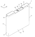
- FIGS. 1A and 1B are a perspective view and a top view, respectively, conceptually showing the power storage device.
- 2 and 3 are an exploded perspective view and an exploded front view of the electricity storage device, respectively.
- the electricity storage device includes a housing case 1, an electrode group 2, a positive electrode external terminal 3, a negative electrode external terminal 4, a positive electrode connection member 5, and a negative electrode connection member 6.
- the storage case 1 is a case in which the electrode group 2 and the electrolytic solution are stored.
- the first main wall 11 and the second main wall 12 that face each other, and the first main wall 11 and the second main wall 11 are opposed to each other.
- the main wall 12 includes a first side wall 13 and a second side wall 14 that connect the left and right sides, a top wall 15, and a bottom wall 16.
- the direction from the first side wall 13 to the second side wall 14 (the width direction of the power storage device) is the X direction
- the direction from the first main wall 11 to the second main wall 12 (the thickness direction of the power storage device).
- a metal such as aluminum or an alloy such as stainless steel as a constituent material of the storage case 1.
- the top wall 15 of the housing case 1 is formed with a rectangular groove-shaped recess 17 that extends in the Y direction and opens into both the first main wall 11 and the second main wall 12. ing. Accordingly, the first main wall 11 and the second main wall 12 are formed with a U-shaped notch that opens the recess 17. And the 1st accommodating part 18 and the 2nd accommodating part 19 are formed in the right and left of the recessed part 17. As shown in FIG. A positive electrode tab 24 to be described later is accommodated in the first accommodating portion 18, and a negative electrode tab 25 to be described later is accommodated in the second accommodating portion 19.
- the recess 17 has a shape that is recessed to a position between the positive electrode tab 24 and the negative electrode tab 25.
- a safety valve 81 and a stopper 82 that blocks the electrolyte injection hole.
- the housing case 1 includes a bottomed cylindrical outer can 71 and a lid 72 that seals the opening 71a of the outer can 71 as shown in FIG.
- the outer can 71 constitutes the first main wall 11, the second main wall 12, the first side wall 13, the second side wall 14, and the bottom wall 16 in the housing case 1.
- the lid 72 constitutes the top wall 15 in which the concave portion 17 is formed in the housing case 1. 2 shows a state in which the electrode group 2 is slightly pulled out from the opening 71a of the outer can 71.
- FIG. 4 is a cutaway end view of the electricity storage device along the line IV-IV shown in FIG.
- the electrode group 2 a plurality of positive plates 21 and a plurality of negative plates 22 are alternately stacked via separators 23.
- each of the positive electrode plates 21 is accommodated in a bag 28 formed of two separators 23 adjacent to each other via the positive electrode plate 21.
- the bag 28 is formed by crimping the edges of the two separators 23 together.
- the electrode group 2 includes both end surfaces 2b and 2c in the stacking direction (matching the Y direction) of the positive electrode plate 21 and the negative electrode plate 22, the inner surface of the first main wall 11 and the second main wall 12 Are accommodated in the housing case 1 in a state of being opposed to the inner surface of each. Further, as shown in FIGS. 2 and 3, in the assembled state of the power storage device, the end surface 2 a of the electrode group 2 directed toward the top wall 15 is closer to the first side wall 13 with respect to the plurality of positive plates 21.
- a plurality of positive electrode tabs 24 provided on the second side wall 14 and a plurality of negative electrode tabs 25 provided closer to the second side wall 14 with respect to the plurality of negative electrode plates 22 protrude. Specifically, it is as follows.
- the positive electrode plate 21 and the negative electrode plate 22 both have a rectangular shape. And in each of the positive electrode plates 21, the one side directed toward the top wall 15 in the assembled state of the electricity storage device is a position close to the end of the one side (the end to be disposed on the first side wall 13 side). In addition, a positive electrode tab 24 is provided. Further, in each of the negative electrode plates 22, one side directed toward the top wall 15 in the assembled state of the electric storage device is a position close to the end of the one side (the end to be disposed on the second side wall 14 side). In addition, a negative electrode tab 25 is provided. In the electrode group 2, the positive electrode plates 21 and the negative electrode plates 22 are alternately stacked such that the positive electrode tabs 24 face each other and the negative electrode tabs 25 face each other at a position away from the positive electrode tab 24. ing.
- all the positive electrode tabs 24 are fastened by rivets 26.
- a conductive spacer 27 is interposed between two adjacent positive electrode tabs 24 in order to prevent deformation of the positive electrode plate 21 and the positive electrode tab 24.
- a metal porous body such as aluminum cermet (registered trademark) that is easily deformed by an external force is used as the positive electrode plate 21.
- all the negative electrode tabs 25 are fastened by rivets 26. Further, in order to prevent the negative electrode plate 22 and the negative electrode tab 25 from being deformed, a conductive spacer is interposed between two adjacent negative electrode tabs 25.
- the positive external terminal 3 is electrically connected to the positive plate 21 via the positive tab 24, and the negative external terminal 4 is connected to the negative plate 22 via the negative tab 25. Electrically connected.
- the positive external terminal 3 and the negative external terminal 4 are provided on a lid 72 constituting the top wall 15 of the housing case 1.
- the positive electrode external terminal 3 is provided on the inner wall 171 of the recess 17 located on the first housing portion 18 (see FIG. 1A) side, and the negative electrode external terminal 4 is disposed on the second housing portion 19 (see FIG. 1A). It is provided on the inner wall 172 of the recess 17 located on the side. That is, the positive external terminal 3 is drawn in the X direction, and the negative external terminal 4 is drawn in the direction opposite to the X direction.
- FIG. 5 is an enlarged view of the main part of the cross section taken along the line VV shown in FIG. 1B. Specifically, FIG. 5 is a cross-sectional view showing the configuration of the positive external terminal 3 and its periphery.
- the positive electrode external terminal 3 is a rivet-type terminal, and has a rivet head portion 31 and a rivet leg portion 32.
- the rivet head 31 is provided with a protrusion 31a that is fitted into a fitting hole 52a of the positive electrode connecting member 5 described later.
- the inner wall 171 of the recess 17 is provided with a through hole 173 that allows the rivet leg portion 32 of the positive external terminal 3 to pass therethrough and prevents the rivet head 31 of the positive external terminal 3 from passing therethrough.
- the diameter of the through hole 173 is designed to be larger than the diameter of the rivet leg portion 32.
- the positive external terminal 3 is attached to the inner wall 171 of the recess 17 as follows. First, the rivet leg portion 32 is passed through the gasket ring 33 made of a rubber material. Thereafter, the rivet leg 32 is passed through the through hole 173 together with the gasket ring 33 so that the rivet head 31 is positioned inside the housing case 1. Thereby, the gasket ring 33 is interposed between the rivet head 31 and the inner wall 171. Next, the gasket ring 34 made of a resin material is attached to the rivet leg portion 32 so that the inner wall 171 is sandwiched between the gasket ring 34 and the gasket ring 33.
- the rivet leg portion 32 is passed through the gasket ring 34.
- the positive external terminal 3 is fixed to the inner wall 171 by caulking the tip of the rivet leg 32. Due to this caulking, the gasket rings 33 and 34 are sandwiched between the rivet head 31 and the caulking portion 35 of the positive external terminal 3, whereby the gasket ring 33 made of a rubber material is compressed. As a result, a part of the gasket ring 33 enters between the inner surface of the through hole 173 and the rivet leg portion 32. In this way, the positive external terminal 3 is attached to the inner wall 171 in a state where the positive external terminal 3 and the lid 72 are electrically insulated from each other by the gasket rings 33 and 34.
- the negative external terminal 4 is a rivet-type terminal similarly to the positive external terminal 3, and is attached to the inner wall 172 of the concave portion 17 by the same method as the above-described attachment method.
- the positive electrode connection member 5 is a member for electrically connecting the positive electrode tab 24 and the positive electrode external terminal 3.
- the positive electrode connection member 5 is formed by bending a single metal plate into an L shape, and includes a first flat plate portion 51 and a second flat plate portion 52.
- the positive electrode connecting member 5 has the first flat plate portion 51 opposed to the positive electrode tab 24 as shown in FIG. 4 and the second flat plate portion 52 as shown in FIG. It arrange
- the first flat plate portion 51 is fixed to the positive electrode tab 24 using a rivet 26 used for fastening the positive electrode tab 24.
- the second flat plate portion 52 is provided with a fitting hole 52a, and in the assembled state of the electricity storage device, a protrusion 31a provided on the rivet head 31 of the positive electrode external terminal 3 is fitted into the fitting hole 52a. ing. Thereby, the 2nd flat plate part 52 and the positive electrode external terminal 3 are mutually connected.
- the positive electrode connection member 5 is not limited to the one having the shape of the present embodiment, and one having another shape that enables electrical connection between the positive electrode tab 24 and the positive electrode external terminal 3 is used. May be.
- the negative electrode connection member 6 is a member for electrically connecting the negative electrode tab 25 and the negative electrode external terminal 4.
- the shape of the negative electrode connection member 6 and the connection mode between the negative electrode tab 25 and the negative electrode external terminal 4 by the negative electrode connection member 6 are the same as the shape and connection mode described above for the positive electrode connection member 5.
- the space in the housing case that was wasted in the square electricity storage device is omitted due to the presence of the recess 17. Therefore, in the electricity storage device, the space factor of the electrode group 2 is increased to 90% or more. Moreover, according to this electrical storage device, the space factor of the electrode group 2 can be increased to 93% or more. Thus, a significantly higher volumetric energy density is realized as compared with conventional power storage devices.
- one long groove 174 is formed by the recess 17 provided in these power storage devices. Then, by arranging a cable such as a harness in the groove 174, the module is gathered together with the cable in a compact manner.
- the positive external terminal 3 is drawn in the X direction
- the negative external terminal 4 is drawn in the direction opposite to the X direction (see FIG. 3). That is, the positive electrode external terminal 3 and the negative electrode external terminal 4 are drawn out in the width direction of the electricity storage device. Therefore, according to the electricity storage device of this embodiment, the positive electrode external terminal 3 and the negative electrode external terminal 4 have high strength against vibration in the width direction of the electricity storage device.
- FIG. 7 is an exploded perspective view of an electricity storage device according to a first modification.
- the structure of the storage case 1 which is a difference with the electrical storage device of the said embodiment is mainly demonstrated in detail.
- the housing case 1 is composed of a bottomed cylindrical outer can 73 and a lid 74 that seals the opening 73a of the outer can 73, as shown in FIG.
- the outer can 73 constitutes the top wall 15, the second main wall 12, the first side wall 13, the second side wall 14, and the bottom wall 16 in which the concave portion 17 is formed in the housing case 1.
- the lid 74 constitutes the first main wall 11 in the housing case 1.
- the space in the housing case that was wasted in the rectangular electricity storage device is omitted due to the presence of the recess 17. Therefore, in the electricity storage device, the space factor of the electrode group 2 is increased to 90% or more. Moreover, according to this electrical storage device, the space factor of the electrode group 2 can be increased to 93% or more. Thus, a significantly higher volumetric energy density is realized as compared with conventional power storage devices.
- FIG. 8 is an exploded perspective view of an electricity storage device according to a second modification.
- the structure of the storage case 1 which is a difference with the electrical storage device of the said embodiment is mainly demonstrated in detail.
- the housing case 1 is composed of two upper and lower case parts 75 and 76 joined to each other on a surface substantially parallel to the bottom wall 16 as shown in FIG.
- substantially parallel means parallel or within ⁇ 1 ° in parallel
- the lower case component 76 is a bottomed cylindrical outer can including a portion that becomes the bottom wall 16 in the housing case 1.
- the upper case part 75 is a lid that seals the opening 76 a of the lower case part 76, and includes a portion that becomes the top wall 15 in the housing case 1.
- the upper case component 76 accommodates the first accommodating portion 18 in which the positive electrode tab 24 is accommodated and the negative electrode tab 25 in the left and right positions of the recess 17 formed in the portion that becomes the top wall 15.
- a second accommodating portion 19 is provided.
- FIG. 8 shows a state in which the electrode group 2 is slightly pulled out from the opening 76a of the lower case component 76.
- the space in the housing case that was wasted in the rectangular electricity storage device is omitted due to the presence of the recess 17. Therefore, in the electricity storage device, the space factor of the electrode group 2 is increased to 90% or more. Moreover, according to this electrical storage device, the space factor of the electrode group 2 can be increased to 93% or more. Thus, a significantly higher volumetric energy density is realized as compared with conventional power storage devices.
- each part structure of this invention is not restricted to the said embodiment and modification, A various deformation
- at least one of the positive external terminal 3 and the negative external terminal 4 may be provided at a position different from the inner wall of the recess 17 in the top wall 15 of the housing case 1.
- the electricity storage device according to the present invention is useful, for example, as a large power storage device for home use or industrial use.
Landscapes
- Engineering & Computer Science (AREA)
- Power Engineering (AREA)
- Chemical & Material Sciences (AREA)
- Chemical Kinetics & Catalysis (AREA)
- Electrochemistry (AREA)
- General Chemical & Material Sciences (AREA)
- Microelectronics & Electronic Packaging (AREA)
- Manufacturing & Machinery (AREA)
- Materials Engineering (AREA)
- Sealing Battery Cases Or Jackets (AREA)
- Connection Of Batteries Or Terminals (AREA)
- Electric Double-Layer Capacitors Or The Like (AREA)
- Secondary Cells (AREA)
Abstract
Description
11 第1主壁
12 第2主壁
13 第1側壁
14 第2側壁
15 天壁
16 底壁
17 凹部
171、172 内壁
173 貫通孔
174 溝
18 第1収容部
19 第2収容部
2 電極群
2a、2b、2c 端面
21 正極板
22 負極板
23 セパレータ
24 正極タブ
25 負極タブ
26 リベット
27 スペーサ
28 袋
3 正極外部端子
31 リベット頭部
31a 突起
32 リベット脚部
33、34 ガスケットリング
35 カシメ部分
4 負極外部端子
5 正極接続部材
51 第1平板部
52 第2平板部
52a 嵌合孔
6 負極接続部材
71 外装缶
71a 開口部
72 蓋体
73 外装缶
73a 開口部
74 蓋体
75、76 ケース部品
76a 開口部
81 安全弁
82 栓
図1A及び図1Bはそれぞれ、蓄電デバイスを概念的に示した斜視図及び上面図である。図2及び図3はそれぞれ、蓄電デバイスの分解斜視図及び分解正面図である。これらの図に示す様に、蓄電デバイスは、収容ケース1と、電極群2と、正極外部端子3と、負極外部端子4と、正極接続部材5と、負極接続部材6とを備えている。
収容ケース1は、電極群2及び電解液が収容されるケースであり、互いに対向した第1主壁11及び第2主壁12と、第1主壁11及び第2主壁12どうしを左右で連結する第1側壁13及び第2側壁14と、天壁15と、底壁16とから構成されている。尚、以下では、第1側壁13から第2側壁14へ向かう方向(蓄電デバイスの幅方向)をX方向、第1主壁11から第2主壁12へ向かう方向(蓄電デバイスの厚さ方向)をY方向、底壁16から天壁15へ向かう方向(蓄電デバイスの高さ方向)をZ方向とする。尚、収容ケース1の構成材料には、収容ケース1の耐食性を高めるべく、アルミニウム等の金属やステンレス鋼等の合金を用いることが好ましい。
図4は、図3に示されるIV-IV線に沿う、蓄電デバイスの切断部端面図である。図4に示す様に、電極群2では、複数の正極板21と複数の負極板22とがセパレータ23を介して交互に積層されている。ここで、正極板21の各々は、この正極板21を介して隣り合う2枚のセパレータ23から形成された袋28に収容されている。具体的には、この袋28は、2枚のセパレータ23の縁どうしを圧着することにより形成されている。
正極外部端子3は、正極タブ24を介して正極板21に電気的に接続され、負極外部端子4は、負極タブ25を介して負極板22に電気的に接続されている。ここで、正極外部端子3及び負極外部端子4は、図3に示す様に、収容ケース1の天壁15を構成する蓋体72に設けられている。具体的には、正極外部端子3は、第1収容部18(図1A参照)側に位置する凹部17の内壁171に設けられ、負極外部端子4は、第2収容部19(図1A参照)側に位置する凹部17の内壁172に設けられている。即ち、正極外部端子3はX方向に引き出され、負極外部端子4はX方向とは反対方向に引き出されている。
正極接続部材5は、正極タブ24と正極外部端子3とを電気的に接続するための部材である。具体的には、正極接続部材5は、1枚の金属板をL字状に折り曲げることにより形成されたものであり、第1平板部51と第2平板部52とを有している。そして、蓄電デバイスの組立て状態において、正極接続部材5は、図4に示す様に第1平板部51が正極タブ24と対向すると共に、図5に示す様に第2平板部52が凹部17の内壁171に対向する様に、配置されている。又、図4に示す様に、第1平板部51は、正極タブ24の締結に用いられるリベット26を利用して、正極タブ24に固定されている。
[2-1]第1変形例
図7は、第1変形例に係る蓄電デバイスの分解斜視図である。尚、以下では、主に、上記実施形態の蓄電デバイスとの相違点である収容ケース1の構成について詳細に説明する。
図8は、第2変形例に係る蓄電デバイスの分解斜視図である。尚、以下では、主に、上記実施形態の蓄電デバイスとの相違点である収容ケース1の構成について詳細に説明する。
Claims (7)
- 複数の正極板と複数の負極板とがセパレータを介して積層された電極群と、
前記電極群が収容された収容ケースと、
前記収容ケースに設けられると共に前記電極群に電気的に接続された外部端子と
を備え、
前記収容ケースは、互いに対向した第1主壁及び第2主壁と、前記第1主壁及び前記第2主壁どうしを左右で連結する第1側壁及び第2側壁と、前記外部端子が設けられた天壁と、底壁とから構成され、
前記電極群は、前記正極板及び前記負極板の積層方向についての両端面を、前記第1主壁の内面及び前記第2主壁の内面にそれぞれ対向させた状態で、前記収容ケースに収容されており、
前記天壁の方へ向けられた前記電極群の端面からは、前記複数の正極板に対して前記第1側壁寄りにそれぞれ設けられた複数の正極タブと、前記複数の負極板に対して前記第2側壁寄りにそれぞれ設けられた複数の負極タブとが突出し、
前記収容ケースの前記天壁には、前記正極タブと前記負極タブとの間の位置まで窪んだ凹部が形成されている、蓄電デバイス。 - 前記凹部は、前記正極タブと前記負極タブとの間を前記積層方向へ延びると共に、前記第1主壁及び前記第2主壁の何れにも開口している、請求項1に記載の蓄電デバイス。
- 前記電極群の占積率が90%以上である、請求項1又は2に記載の蓄電デバイス。
- 前記収容ケースは、有底筒状の外装缶と、前記外装缶の開口部を封止する蓋体とから構成されており、
前記外装缶は、前記収容ケースにおいて、前記第1主壁、前記第2主壁、前記第1側壁、前記第2側壁、及び前記底壁を構成し、
前記蓋体は、前記収容ケースにおいて、前記凹部が形成されている前記天壁を構成する、請求項1~3の何れか1つに記載の蓄電デバイス。 - 前記収容ケースは、有底筒状の外装缶と、前記外装缶の開口部を封止する蓋体とから構成されており、
前記外装缶は、前記収容ケースにおいて、前記凹部が形成されている前記天壁、前記第2主壁、前記第1側壁、前記第2側壁、及び前記底壁を構成し、
前記蓋体は、前記収容ケースにおいて、前記第1主壁を構成する、請求項1~3の何れか1つに記載の蓄電デバイス。 - 前記収容ケースは、前記底壁に略平行な面で互いに接合される上下2つのケース部品から構成されており、
下側の前記ケース部品は、前記収容ケースにおいて前記底壁となる部分を含んだ有底筒状の外装缶であり、
上側の前記ケース部品は、下側の前記ケース部品の開口部を封止する蓋体であり、前記収容ケースにおいて前記天壁となる部分を含み、
上側の前記ケース部品には、前記天壁となる前記部分に形成されている前記凹部の左右の位置に、前記正極タブが収容される第1収容部と、前記負極タブが収容される第2収容部とがそれぞれ設けられている、請求項1~3の何れか1つに記載の蓄電デバイス。 - 前記外部端子は、
前記正極タブに電気的に接続された正極外部端子と、
前記負極タブに電気的に接続された負極外部端子と
を含み、
前記正極外部端子及び前記負極外部端子の少なくとも何れか一方は、前記凹部を構成する内壁に設けられている、請求項1~6の何れか1つに記載の蓄電デバイス。
Priority Applications (4)
| Application Number | Priority Date | Filing Date | Title |
|---|---|---|---|
| CN201580006915.6A CN105960693A (zh) | 2014-02-05 | 2015-01-29 | 蓄电设备 |
| EP15745750.8A EP3104384A4 (en) | 2014-02-05 | 2015-01-29 | Power storage device |
| KR1020167018436A KR20160117431A (ko) | 2014-02-05 | 2015-01-29 | 축전 디바이스 |
| US15/116,729 US20160351345A1 (en) | 2014-02-05 | 2015-01-29 | Electricity storage device |
Applications Claiming Priority (2)
| Application Number | Priority Date | Filing Date | Title |
|---|---|---|---|
| JP2014020668A JP2015149362A (ja) | 2014-02-05 | 2014-02-05 | 蓄電デバイス |
| JP2014-020668 | 2014-02-05 |
Publications (1)
| Publication Number | Publication Date |
|---|---|
| WO2015119027A1 true WO2015119027A1 (ja) | 2015-08-13 |
Family
ID=53777834
Family Applications (1)
| Application Number | Title | Priority Date | Filing Date |
|---|---|---|---|
| PCT/JP2015/052439 WO2015119027A1 (ja) | 2014-02-05 | 2015-01-29 | 蓄電デバイス |
Country Status (6)
| Country | Link |
|---|---|
| US (1) | US20160351345A1 (ja) |
| EP (1) | EP3104384A4 (ja) |
| JP (1) | JP2015149362A (ja) |
| KR (1) | KR20160117431A (ja) |
| CN (1) | CN105960693A (ja) |
| WO (1) | WO2015119027A1 (ja) |
Cited By (1)
| Publication number | Priority date | Publication date | Assignee | Title |
|---|---|---|---|---|
| CN108400262A (zh) * | 2017-02-06 | 2018-08-14 | 丰田自动车株式会社 | 密闭型电池和电池组 |
Families Citing this family (8)
| Publication number | Priority date | Publication date | Assignee | Title |
|---|---|---|---|---|
| DE112016001474T5 (de) | 2015-03-31 | 2017-12-14 | Gs Yuasa International Ltd. | Energiespeichergerät |
| JP6593304B2 (ja) | 2016-11-07 | 2019-10-23 | トヨタ自動車株式会社 | 蓄電デバイスおよび蓄電デバイスの製造方法 |
| JP6970912B2 (ja) * | 2017-09-12 | 2021-11-24 | 株式会社Gsユアサ | 蓄電素子、及び蓄電素子を備える蓄電装置 |
| CN117795717A (zh) * | 2021-10-13 | 2024-03-29 | 株式会社杰士汤浅国际 | 蓄电元件 |
| CN116438709A (zh) * | 2021-11-01 | 2023-07-14 | 宁德时代新能源科技股份有限公司 | 电池单体、电池、用电设备、制造电池单体的方法和设备 |
| CN216872125U (zh) * | 2022-02-21 | 2022-07-01 | 宁德时代新能源科技股份有限公司 | 电池单体、电池和用电设备 |
| CN217719785U (zh) * | 2022-07-19 | 2022-11-01 | 宁德时代新能源科技股份有限公司 | 电池单体、电池及用电装置 |
| WO2024045048A1 (zh) * | 2022-08-31 | 2024-03-07 | 宁德时代新能源科技股份有限公司 | 电池单体、电池以及用电装置 |
Citations (5)
| Publication number | Priority date | Publication date | Assignee | Title |
|---|---|---|---|---|
| JP2009266695A (ja) * | 2008-04-25 | 2009-11-12 | Toyota Motor Corp | 電池の製造方法及び組電池 |
| US20100143795A1 (en) * | 2006-10-02 | 2010-06-10 | Kenneth Michael Partington | Battery and a Process for Making a Battery |
| JP2010160931A (ja) * | 2009-01-07 | 2010-07-22 | Mitsubishi Motors Corp | 二次電池の保持構造 |
| JP2011171079A (ja) * | 2010-02-17 | 2011-09-01 | Toshiba Corp | 電池 |
| WO2012105491A1 (ja) * | 2011-01-31 | 2012-08-09 | 株式会社Gsユアサ | 蓄電素子 |
Family Cites Families (8)
| Publication number | Priority date | Publication date | Assignee | Title |
|---|---|---|---|---|
| CN1655389A (zh) * | 2005-03-04 | 2005-08-17 | 北京中信国安盟固利新材料技术研究院有限公司 | 大容量金属外壳锂离子二次电池 |
| JP5025276B2 (ja) * | 2007-01-31 | 2012-09-12 | 三洋電機株式会社 | アルカリ蓄電池およびその製造方法 |
| JP2011204469A (ja) | 2010-03-25 | 2011-10-13 | Sanyo Electric Co Ltd | 角形密閉二次電池 |
| JP5543269B2 (ja) * | 2010-05-12 | 2014-07-09 | シャープ株式会社 | 二次電池 |
| JP2012114066A (ja) * | 2010-11-02 | 2012-06-14 | Sharp Corp | 二次電池 |
| WO2012140707A1 (ja) * | 2011-04-11 | 2012-10-18 | パナソニック株式会社 | 薄型電池および電池デバイス |
| JP6048080B2 (ja) * | 2011-11-29 | 2016-12-21 | 株式会社Gsユアサ | 蓄電素子 |
| JP5861524B2 (ja) * | 2012-03-23 | 2016-02-16 | 株式会社豊田自動織機 | 蓄電モジュール |
-
2014
- 2014-02-05 JP JP2014020668A patent/JP2015149362A/ja active Pending
-
2015
- 2015-01-29 CN CN201580006915.6A patent/CN105960693A/zh active Pending
- 2015-01-29 EP EP15745750.8A patent/EP3104384A4/en not_active Withdrawn
- 2015-01-29 WO PCT/JP2015/052439 patent/WO2015119027A1/ja active Application Filing
- 2015-01-29 US US15/116,729 patent/US20160351345A1/en not_active Abandoned
- 2015-01-29 KR KR1020167018436A patent/KR20160117431A/ko not_active Application Discontinuation
Patent Citations (5)
| Publication number | Priority date | Publication date | Assignee | Title |
|---|---|---|---|---|
| US20100143795A1 (en) * | 2006-10-02 | 2010-06-10 | Kenneth Michael Partington | Battery and a Process for Making a Battery |
| JP2009266695A (ja) * | 2008-04-25 | 2009-11-12 | Toyota Motor Corp | 電池の製造方法及び組電池 |
| JP2010160931A (ja) * | 2009-01-07 | 2010-07-22 | Mitsubishi Motors Corp | 二次電池の保持構造 |
| JP2011171079A (ja) * | 2010-02-17 | 2011-09-01 | Toshiba Corp | 電池 |
| WO2012105491A1 (ja) * | 2011-01-31 | 2012-08-09 | 株式会社Gsユアサ | 蓄電素子 |
Non-Patent Citations (1)
| Title |
|---|
| See also references of EP3104384A4 * |
Cited By (2)
| Publication number | Priority date | Publication date | Assignee | Title |
|---|---|---|---|---|
| CN108400262A (zh) * | 2017-02-06 | 2018-08-14 | 丰田自动车株式会社 | 密闭型电池和电池组 |
| CN108400262B (zh) * | 2017-02-06 | 2021-05-18 | 丰田自动车株式会社 | 密闭型电池和电池组 |
Also Published As
| Publication number | Publication date |
|---|---|
| EP3104384A1 (en) | 2016-12-14 |
| CN105960693A (zh) | 2016-09-21 |
| US20160351345A1 (en) | 2016-12-01 |
| JP2015149362A (ja) | 2015-08-20 |
| EP3104384A4 (en) | 2017-03-15 |
| KR20160117431A (ko) | 2016-10-10 |
Similar Documents
| Publication | Publication Date | Title |
|---|---|---|
| WO2015119027A1 (ja) | 蓄電デバイス | |
| JP6220849B2 (ja) | 大型電気化学エネルギー貯蔵装置ハウジングおよびモジュール | |
| EP4016569A1 (en) | Power storage element | |
| JP6124175B2 (ja) | 蓄電素子 | |
| KR102444124B1 (ko) | 배터리 모듈 및 이를 포함하는 배터리 팩 | |
| US20150171404A1 (en) | Battery module | |
| CN110268548B (zh) | 蓄电装置 | |
| JP5625294B2 (ja) | 電池モジュール | |
| CN109075269A (zh) | 多腔室蓄电池模块 | |
| JP2017216095A (ja) | 電池モジュール | |
| JP6396033B2 (ja) | 電池モジュールおよび電池セル | |
| JP2016162755A (ja) | カバーを有する二次電池 | |
| JP2014179298A (ja) | 電源モジュール | |
| JP2015204248A (ja) | 角型電池用電気絶縁シート、角型電池、及び角型電池の製造方法 | |
| JP6170937B2 (ja) | 蓄電デバイスおよび蓄電モジュール | |
| JP6455081B2 (ja) | 蓄電装置 | |
| JP2023108022A (ja) | 二次電池 | |
| WO2015163230A1 (ja) | 蓄電装置 | |
| JP2013222517A (ja) | 角形二次電池 | |
| JP6155724B2 (ja) | 蓄電素子及び蓄電素子の製造方法 | |
| US20120214029A1 (en) | Rechargeable battery | |
| KR20130116807A (ko) | 전지 | |
| JP6451093B2 (ja) | 蓄電装置 | |
| JP6354454B2 (ja) | 蓄電装置 | |
| JP2019175719A (ja) | 燃料電池システム |
Legal Events
| Date | Code | Title | Description |
|---|---|---|---|
| 121 | Ep: the epo has been informed by wipo that ep was designated in this application |
Ref document number: 15745750 Country of ref document: EP Kind code of ref document: A1 |
|
| ENP | Entry into the national phase |
Ref document number: 20167018436 Country of ref document: KR Kind code of ref document: A |
|
| REEP | Request for entry into the european phase |
Ref document number: 2015745750 Country of ref document: EP |
|
| WWE | Wipo information: entry into national phase |
Ref document number: 2015745750 Country of ref document: EP |
|
| WWE | Wipo information: entry into national phase |
Ref document number: 15116729 Country of ref document: US |
|
| NENP | Non-entry into the national phase |
Ref country code: DE |