WO2012093711A1 - モータ制御装置及び電動パワーステアリング装置 - Google Patents
モータ制御装置及び電動パワーステアリング装置 Download PDFInfo
- Publication number
- WO2012093711A1 WO2012093711A1 PCT/JP2012/050144 JP2012050144W WO2012093711A1 WO 2012093711 A1 WO2012093711 A1 WO 2012093711A1 JP 2012050144 W JP2012050144 W JP 2012050144W WO 2012093711 A1 WO2012093711 A1 WO 2012093711A1
- Authority
- WO
- WIPO (PCT)
- Prior art keywords
- phase
- current
- value
- motor control
- abnormality
- Prior art date
Links
Images


Classifications
-
- H—ELECTRICITY
- H02—GENERATION; CONVERSION OR DISTRIBUTION OF ELECTRIC POWER
- H02P—CONTROL OR REGULATION OF ELECTRIC MOTORS, ELECTRIC GENERATORS OR DYNAMO-ELECTRIC CONVERTERS; CONTROLLING TRANSFORMERS, REACTORS OR CHOKE COILS
- H02P29/00—Arrangements for regulating or controlling electric motors, appropriate for both AC and DC motors
- H02P29/02—Providing protection against overload without automatic interruption of supply
- H02P29/024—Detecting a fault condition, e.g. short circuit, locked rotor, open circuit or loss of load
- H02P29/0241—Detecting a fault condition, e.g. short circuit, locked rotor, open circuit or loss of load the fault being an overvoltage
-
- B—PERFORMING OPERATIONS; TRANSPORTING
- B62—LAND VEHICLES FOR TRAVELLING OTHERWISE THAN ON RAILS
- B62D—MOTOR VEHICLES; TRAILERS
- B62D5/00—Power-assisted or power-driven steering
- B62D5/04—Power-assisted or power-driven steering electrical, e.g. using an electric servo-motor connected to, or forming part of, the steering gear
- B62D5/0457—Power-assisted or power-driven steering electrical, e.g. using an electric servo-motor connected to, or forming part of, the steering gear characterised by control features of the drive means as such
- B62D5/0481—Power-assisted or power-driven steering electrical, e.g. using an electric servo-motor connected to, or forming part of, the steering gear characterised by control features of the drive means as such monitoring the steering system, e.g. failures
- B62D5/049—Power-assisted or power-driven steering electrical, e.g. using an electric servo-motor connected to, or forming part of, the steering gear characterised by control features of the drive means as such monitoring the steering system, e.g. failures detecting sensor failures
-
- H—ELECTRICITY
- H02—GENERATION; CONVERSION OR DISTRIBUTION OF ELECTRIC POWER
- H02M—APPARATUS FOR CONVERSION BETWEEN AC AND AC, BETWEEN AC AND DC, OR BETWEEN DC AND DC, AND FOR USE WITH MAINS OR SIMILAR POWER SUPPLY SYSTEMS; CONVERSION OF DC OR AC INPUT POWER INTO SURGE OUTPUT POWER; CONTROL OR REGULATION THEREOF
- H02M1/00—Details of apparatus for conversion
- H02M1/32—Means for protecting converters other than automatic disconnection
-
- H—ELECTRICITY
- H02—GENERATION; CONVERSION OR DISTRIBUTION OF ELECTRIC POWER
- H02P—CONTROL OR REGULATION OF ELECTRIC MOTORS, ELECTRIC GENERATORS OR DYNAMO-ELECTRIC CONVERTERS; CONTROLLING TRANSFORMERS, REACTORS OR CHOKE COILS
- H02P27/00—Arrangements or methods for the control of AC motors characterised by the kind of supply voltage
- H02P27/04—Arrangements or methods for the control of AC motors characterised by the kind of supply voltage using variable-frequency supply voltage, e.g. inverter or converter supply voltage
- H02P27/06—Arrangements or methods for the control of AC motors characterised by the kind of supply voltage using variable-frequency supply voltage, e.g. inverter or converter supply voltage using dc to ac converters or inverters
- H02P27/08—Arrangements or methods for the control of AC motors characterised by the kind of supply voltage using variable-frequency supply voltage, e.g. inverter or converter supply voltage using dc to ac converters or inverters with pulse width modulation
Definitions
- the present invention relates to a motor control device and an electric power steering device.
- an abnormality mode (sensor abnormality) of the current sensor can be cited as an abnormality mode in which continuous control by two-phase driving can be executed. That is, when an abnormality (for example, an amplifier failure) occurs in a current sensor provided corresponding to each phase, the output level may become an abnormal value (for example, a current detection limit value (upper limit) Value or lower limit value) is fixed in the vicinity (so-called Hi / Lo sticking), etc.). In this case, if the actual power supply path is all normal and the abnormality that has occurred is only the sensor abnormality, at least as long as only two phases other than the abnormality occurrence phase are energized phases, The motor drive can be continued.
- an abnormality for example, an amplifier failure
- the output level may become an abnormal value (for example, a current detection limit value (upper limit) Value or lower limit value) is fixed in the vicinity (so-called Hi / Lo sticking), etc.).
- the present invention has been made to solve the above-described problems, and its purpose is to accurately detect the occurrence of a sensor abnormality by distinguishing it from a short-circuit abnormality that has occurred in each switching element constituting the drive circuit.
- An object of the present invention is to provide a motor control device and an electric power steering device.
- a motor control device includes a current detection means for detecting a three-phase current value energized by a motor, and a PWM carrier that generates a triangular wave based on each phase current value.
- Motor control signal output means for outputting a motor control signal by executing the current control, and a drive circuit for outputting drive power to the motor based on the motor control signal, the drive circuit comprising the motor
- a switching arm formed by connecting a pair of switching elements that are turned on / off based on a control signal in series is connected in parallel corresponding to each phase, and a current is applied to the low potential side of each switching arm.
- a sensor is provided, and the current detection means acquires the output signal of each current sensor at a timing when the triangular wave becomes a peak.
- the first current value and the second current value of each phase are detected by acquiring the output signal of each current sensor at the timing when the triangular wave becomes a valley, and each first current value and each second current is detected.
- a motor control device that detects a phase current value of each phase based on a difference between values, and is generated in a power supply path of each phase based on the first current value, the second current value, and the phase current.
- An abnormality detection means for detecting an abnormality wherein the abnormality detection means has at least one of an absolute value of the first current value and an absolute value of the second current value in any phase as a limit value for current detection. If the absolute value of the phase current value is smaller than the second threshold value corresponding to zero, the current sensor is determined to be abnormal for the phase.
- the first current value and the second current value of the abnormality occurrence phase may be constant at values near the limit value of current detection.
- the phase current value which is the difference between them is also constant at a value in the vicinity of “0”. Therefore, according to the said structure, generation
- the motor control signal output means executes the output of the motor control signal with two phases other than the abnormality occurrence phase as energized phases.
- region of the continuous control by two-phase drive can be expanded, ensuring safety
- the abnormality detection means has an absolute value of the phase current value exceeding a third threshold value corresponding to the limit value, and the first current value or the second current value is a lower limit value of the current detection. Is lower than the fourth threshold value corresponding to, it is determined that there is a short circuit abnormality in the switching element for the phase.
- each current sensor when each current sensor is provided on the low potential side of each switching arm constituting the drive circuit, a short circuit abnormality occurs in any one of the switching elements, thereby causing the first current value (when the upper stage is short-circuited). ) Or the second current value (when the upper stage is short-circuited) shows a value near the lower limit of the current detection.
- the electric power steering apparatus provided by the present invention is an electric power steering apparatus including the above-described motor control apparatus. According to the above configuration, the occurrence of sensor abnormality can be detected with high accuracy. As a result, it is possible to expand the execution area of the continuous control by the two-phase drive while ensuring safety. Even when the sensor abnormality occurs, the assist force is continuously applied to the steering system, thereby suppressing the increase of the steering force and reducing the driver's load.
- a motor control device and an electric power steering device capable of accurately detecting the occurrence of a sensor abnormality by distinguishing from a short circuit abnormality occurring in each switching element constituting the drive circuit.
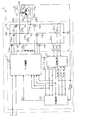
- the schematic block diagram of an electric power steering device (EPS).
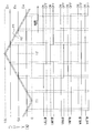
- Explanatory drawing which shows the aspect of the current control which used the triangular wave as the PWM carrier.
- the flowchart which shows the process sequence of electric current detection.
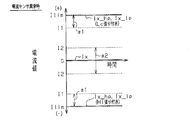
- Explanatory drawing which shows each phase current value at the time of current sensor abnormality generation
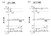
- (A), (b) is explanatory drawing which shows each phase current value at the time of short circuit abnormality generation
- the flowchart which shows the process sequence of a short circuit abnormality detection.
- the flowchart which shows the aspect of the motor control according to each abnormality detection and its abnormality mode.
- EPS electric power steering apparatus
- a steering shaft 3 to which a steering 2 is fixed is connected to a rack shaft 5 via a rack and pinion mechanism 4.
- the rotation of the steering shaft 3 accompanying the operation is converted into a reciprocating linear motion of the rack shaft 5 by the rack and pinion mechanism 4.
- the steering shaft 3 of this embodiment is formed by connecting a column shaft 3a, an intermediate shaft 3b, and a pinion shaft 3c.
- the EPS 1 includes an EPS actuator 10 as a steering force assisting device that applies an assist force for assisting a steering operation to the steering system, and an ECU 11 as a control unit that controls the operation of the EPS actuator 10. .
- the EPS actuator 10 of this embodiment is configured as a so-called column-type EPS actuator in which a motor 12 as a driving source is drivingly connected to a column shaft 3a via a speed reduction mechanism 13.
- a brushless motor is employed as the motor 12 of the present embodiment, and the motor 12 rotates by receiving supply of three-phase (U, V, W) driving power from the ECU 11.
- the EPS actuator 10 is configured to apply the motor torque as an assist force to the steering system by decelerating and transmitting the rotation of the motor 12 to the column shaft 3a.
- a torque sensor 14 and a vehicle speed sensor 15 are connected to the ECU 11, and the ECU 11 detects the steering torque ⁇ and the vehicle speed V based on the output signals of these sensors. Then, the ECU 11 calculates a target assist force based on the steering torque ⁇ and the vehicle speed V, and supplies the drive power to the motor 12 that is the drive source in order to cause the EPS actuator 10 to generate the target assist force.
- the operation of the EPS actuator 10, that is, the assist force applied to the steering system is controlled (power assist control).
- FIG. 2 is a control block diagram of the EPS of this embodiment.
- the ECU 11 includes a microcomputer 17 that outputs a motor control signal, and a drive circuit 18 that supplies three-phase drive power to the motor 12 based on the motor control signal output from the microcomputer 17. Yes.
- the drive circuit 18 of the present embodiment is formed by connecting each series of FETs 18a and 18d, FETs 18b and 18e, and FETs 18c and 18f in parallel.
- the connection points 19u, 19v, and 19w of the FETs 18a and 18d, the FETs 18b and 18e, and the FETs 18c and 18f are connected to the motor coils 12u, 12v, and 12w of each phase of the motor 12, respectively.
- the drive circuit 18 of the present embodiment is formed by connecting three switching arms 18u, 18v, and 18w corresponding to each phase in parallel with a pair of switching elements connected in series as a basic unit (switching arm). It is configured as a known PWM inverter.
- the motor control signal output from the microcomputer 17 is a gate on / off signal that defines the switching state (on / off operation) of each of the FETs 18a to 18f constituting the drive circuit 18.
- each of the FETs 18a to 18f constituting the drive circuit 18 is turned on / off when a control voltage based on the motor control signal is applied to its gate terminal. Then, the three-phase drive power is supplied to the motor 12 by switching the energization pattern to the motor coils 12u, 12v, 12w of each phase.
- the microcomputer 17 includes the DUTY instruction values Du, Dv, Dw corresponding to the phase voltages to be applied to the motor coils 12u, 12v, 12w of each phase and the PWM carrier.
- a motor control signal to be output to the drive circuit 18 is generated based on the comparison with the triangular wave (carrier wave).
- a dead time is set in order to avoid the occurrence of a through current due to a so-called arm short circuit. Yes.
- the microcomputer 17 corresponds to the phase when each DUTY instruction value Du, Dv, Dw is higher than the value of the triangular wave ⁇ 1 in the comparison with the triangular wave ⁇ 1 located on the upper side in FIG.
- a motor control signal is generated to turn on each FET 18a, 18b, 18c on the high potential side (upper stage), and to turn off each FET 18a, 18b, 18c when the FET is low.
- the DUTY instruction values Du, Dv, and Dw are lower than the value of the triangular wave ⁇ 2 in comparison with the triangular wave ⁇ 2 on the lower side, the low potential side (lower stage) corresponding to the phase.
- the FETs 18d, 18e, and 18f are turned on, and when they are high, the motor control signals are generated so as to turn off the FETs 18d, 18e, and 18f.
- each switching arm 18u, 18v, 18w constituting the driving circuit 18 has a low potential side (ground side, lower side in FIG. 2) in each phase.
- Corresponding current sensors 20u, 20v, 20w are provided. Each of these current sensors 20u, 20v, and 20w has a known configuration that amplifies and outputs the voltage across the terminals of the shunt resistor connected in series to each of the switching arms 18u, 18v, and 18w. .
- the microcomputer 17 of the present embodiment detects the phase current values Iu, Iv, and Iw that are energized to the motor 12 based on the output signals Si_u, Si_v, and Si_w of the current sensors 20u, 20v, and 20w.
- the current detection unit 21 provided in the microcomputer 17 acquires the output signals Si_u, Si_v, Si_w of the current sensors 20u, 20v, 20w at a predetermined sampling timing. Specifically, as shown in FIG. 3, the triangular wave ( ⁇ 1, ⁇ 2) as the PWM carrier becomes the “valley (minimum value)” timing (T1 in the figure) and the “mountain (maximum value)”.
- the output signals Si_u, Si_v, and Si_w of the current sensors 20u, 20v, and 20w are acquired at the timing (T2 in the figure).
- the “peak timing” and “valley timing” are, of course, peak timings at which the values of the triangular waves ( ⁇ 1, ⁇ 2) are “maximum” and “minimum”, respectively.
- the current detection unit 21 detects the phase current values Iu, Iv, Iw of the motor 12 based on the output signals Si_u, Si_v, Si_w acquired at these two timings.
- the current detection unit 21 as the current detection unit acquires the output signals Si_u, Si_v, Si_w of the current sensors 20 u, 20 v, 20 w at the respective sampling timings. (Step 101) Subsequently, the output signals Si_u, Si_v, and Si_w are A / D converted (Step 102).
- the first current value Iu_hp corresponding to the sampling timing at which the triangular wave ( ⁇ 1, ⁇ 2) as the PWM carrier becomes “mountain (maximum value)”
- the second current values Iu_lp, Iv_lp, Iw_lp corresponding to the sampling timing at which the Iv_hp, Iw_hp and the triangular wave ( ⁇ 1, ⁇ 2) as the PWM carrier become “valley (minimum value)” are detected (step 103).
- the phase current values Iu, Iv, Iw detected by the current detector 21 together with the steering torque ⁇ and the vehicle speed V are used as motor control signal output means.
- the motor control unit 22 receives the motor rotation angle ⁇ detected by the motor resolver 23.
- the microcomputer 17 generates a motor control signal to be output to the drive circuit 18 by executing current control based on each of these state quantities in the motor control unit 22.
- the motor control unit 22 calculates a current command value corresponding to the assist force (target assist force) to be applied to the steering system based on the steering torque ⁇ and the vehicle speed V. Specifically, a current command value is calculated such that the greater the detected steering torque ⁇ and the lower the vehicle speed V, the greater assist force is generated. And the motor control part 22 produces
- the motor control unit 22 converts the phase current values Iu, Iv, Iw detected as the actual current values based on the motor rotation angle ⁇ into the d axis of the d / q coordinate system. Convert to current value and q-axis current value. The motor control unit 22 calculates a q-axis current command value as the current command value (d-axis current command value is zero).
- the motor control unit 22 compares each DUTY instruction value Du, Dv, Dw based on each phase voltage command value calculated in this way with the triangular wave ( ⁇ 1, ⁇ 2) that is the PWM carrier as described above. Thus, a motor control signal is generated.
- the microcomputer 17 outputs the motor control signal to the drive circuit 18, the drive power for generating the target assist force is supplied to the motor 12 that is the drive source of the EPS actuator 10. It has come to be.
- the microcomputer 17 of the present embodiment is provided with an abnormality detection unit 25 that detects an abnormality that has occurred in the power supply path between the drive circuit 18 and the motor 12.
- the abnormality detection unit 25 serving as the abnormality detection means includes phase current values Iu, Iv, Iw detected by the current detection unit 21, and DUTY instruction values calculated by the motor control unit 22. Du, Dv, Dw and motor rotation angular velocity ⁇ are input.
- the abnormality detection part 25 detects generation
- the detection result by the abnormality detection unit 25 is input to the motor control unit 22 as the abnormality detection signal Str. Then, when the abnormality detection signal Str indicates that an energization failure has occurred and the energization failure occurrence phase is only one phase, the motor control unit 22 determines two phases other than the energization failure occurrence phase as the energization phase. In order to continue the supply of driving power to the motor 12, the motor control signal is generated.
- the cause of such an energization failure is an open (fixed) abnormality of each FET 18a to 18f constituting the drive circuit 18, and between the drive circuit 18 and the motor coils 12u, 12v, 12w of each phase. Disconnection of the power supply lines 26u, 26v, 26w, etc. Then, details of energization failure detection based on each of the above state quantities (phase current value, DUTY instruction value, and motor rotation angular velocity) and continuation control (two-phase drive) in which two phases other than the energization failure occurrence phase are energized phases. For example, refer to the descriptions in Patent Document 1, Patent Document 2, and the like.
- the abnormality detection unit 25 of the present embodiment includes the first current values Iu_hp, Iv_hp, Iw_hp and the second current values Iu_lp, Iv_lp, Iw_lp of the phases detected by the current detection unit 21 together with the state quantities. Is entered. Then, the abnormality detection unit 25 is based on the first current values Iu_hp, Iv_hp, Iw_hp and the second current values Iu_lp, Iv_lp, Iw_lp of each phase and the phase current values Iu, Iv, Iw of each phase. Abnormalities of the current sensors 20u, 20v, 20w (sensor abnormalities) and short-circuit abnormalities occurring in the FETs 18a to 18f constituting the drive circuit 18 are detected.
- the values of the output signals Si_u, Si_v, and Si_w are constant near the output limit (so-called Hi / Lo sticking). It may become.
- the phase current value Ix which is the difference between them, is also constant at a value in the vicinity of “0” (region ⁇ 2 in the figure).
- the abnormality detection unit 25 of the present embodiment is configured such that the first current values Iu_hp, Iv_hp, and Iw_hp detected by the current detection unit 21 and the second current values Iu_lp, Iv_lp, and Iw_lp are absolute values. It is determined whether at least one of the values exceeds a first threshold value I1 set in correspondence with the current detection limit value ( ⁇ Ilim). Further, the abnormality detection unit 25 determines whether or not the absolute values of the detected phase current values Iu, Iv, and Iw are smaller than the second threshold value I2 set corresponding to “0 (zero)”. judge. When there is a phase that satisfies both of these two determination conditions, it is determined that the sensor abnormality (sticking abnormality) has occurred in the phase.
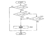
- step 201 when the abnormality detection unit 25 determines in step 201 that the absolute value of the first current value Ix_hp exceeds the first threshold value I1 (
- step 202 when it is determined in step 202 that the absolute value of the second current value Ix_lp exceeds the first threshold value I1 (
- step 204 If the absolute value of the phase current value Ix is smaller than the second threshold value I2 (
- the abnormality detection unit 25 of the present embodiment determines that the absolute value of the second current value Ix_lp is equal to or less than the first threshold value I1 (
- step 203 when the absolute value of the phase current value Ix is equal to or greater than the second threshold value I2 (
- phase current value Ix of the short-circuit abnormality occurrence phase indicates a value in the vicinity of the current detection limit value ( ⁇ Ilim) (region ⁇ 3 in the figure).
- the current detection unit 21 As the second current value Ix_lp of the abnormality occurrence phase to be detected, the through current having a value in the vicinity of the current detection lower limit ( ⁇ Ilim) (region ⁇ 4 in the figure) is detected. At this time, the lower FET is short-circuited to the ground, so that the first current value Ix_hp is theoretically substantially “0 (zero)”. Therefore, in this case, the phase current value Ix, which is the difference between the two, indicates a value in the vicinity of the current detection limit value (upper limit: + Ilim) (region ⁇ 3 in the figure).
- the first current value Ix_hp is generated due to the occurrence of the short circuit abnormality.
- the second current value Ix_lp indicates a value near the lower limit ( ⁇ Ilim) of the current detection.
- the absolute value of each phase current value Iu, Iv, Iw detected by the current detection unit 21 corresponds to the limit value ( ⁇ Ilim) of the current detection. Then, it is determined whether or not the third threshold value I3 set is exceeded.
- the abnormality detection unit 25 corresponds to the absolute value of the first current value Iu_hp, Iv_hp, Iw_hp or each of the second current values Iu_lp, Iv_lp, Iw_lp corresponding to the lower limit ( ⁇ Ilim) of the current detection. It is determined whether it is lower than the set fourth threshold I4.
- the fourth threshold value I4 has a negative sign similar to the lower limit value, and is set so that its absolute value is smaller than the third threshold value I3. And when there exists a phase which satisfy
- step 301 when the abnormality detection unit 25 determines in step 301 that the absolute value (
- Step 304 When it is determined in these two steps that the first current value Ix_hp is lower than the fourth threshold value I4 (Ix_hp ⁇ I4: step 302: YES), or the second current value Ix_lp is the fourth threshold value. If it is determined that it is lower than I4 (Ix_lp ⁇ I4: Step 302: YES), it is determined that the short-circuit abnormality has occurred in the X phase (Step 304).
- the abnormality detection unit 25 determines that the absolute value (
- the abnormality detection unit 25 performs the sensor abnormality determination process (see FIG. 6, steps 201 to 204) and the short-circuit abnormality detection process (see FIG. 6) for each phase of U, V, and W. 8, step 301 to step 304) are executed. Then, an abnormality detection signal Str including the results of the sensor abnormality detection and the short circuit abnormality detection is output to the motor control unit 22.
- the motor control unit 22 determines whether or not the abnormality detection signal Str input from the abnormality detection unit 25 indicates the occurrence of the sensor abnormality. Determines whether or not the sensor abnormality occurrence phase is only one phase, that is, whether or not two normal phases remain. If the abnormality detection signal Str indicates that a sensor abnormality has occurred and the phase in which the sensor abnormality has occurred is only one phase, the two phases other than the sensor abnormality occurrence phase are energized in the same manner as in the case of the energization failure. In order to continue supplying the driving power to the motor 12 as a phase, the motor control signal is generated (continuous control).
- the motor control unit 22 of the present embodiment determines whether or not the abnormality detection signal Str input from the abnormality detection unit 25 indicates the occurrence of the short circuit abnormality.
- the motor control is stopped and the fail-safe operation is promptly achieved.
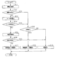
- the microcomputer 17 first performs the energization failure detection (step 401), and if it is determined that no energization failure has occurred (step 402: NO), the microcomputer 17 continues. Then, the sensor abnormality detection is executed (step 403, see FIG. 6). Further, if the microcomputer 17 determines that the sensor abnormality has not occurred based on the sensor abnormality detection result (step 404: NO), the microcomputer 17 subsequently performs the short-circuit abnormality detection (step 405, FIG. 8). When it is determined that the short circuit abnormality has not occurred based on the detection result of the short circuit abnormality (step 406: NO), a motor control signal is supplied to supply three-phase drive power to the motor 12. Generate (normal control, step 407).
- the microcomputer 17 determines that an energization failure has occurred in step 402 (step 402: YES), or if it is determined in step 404 that a sensor abnormality has occurred (step 404: YES), it is determined whether or not there is only one phase in which an abnormality has occurred, that is, two phases that can be energized remain (step 408).
- the motor control signal is used to continue the supply of drive power to the motor 12 with two phases other than the abnormality occurrence phase as energized phases. Is generated (continuous control, step 409).
- the microcomputer 17 determines that a short-circuit abnormality has occurred in step 406 (step 406: YES), or determines that no two phases that can be energized remain in step 408 (step 408: If YES, the motor control is stopped (step 410).
- the abnormality detection unit 25 corresponds to at least one of the absolute value of the detected first current value Ix_hp and the absolute value of each second current value Ix_lp corresponding to the limit value ( ⁇ Ilim) of the current detection. It is determined whether or not the set first threshold value I1 is exceeded. Further, the abnormality detection unit 25 determines whether or not the absolute value of each detected phase current value Ix is smaller than a second threshold value I2 set corresponding to “0 (zero)”. When there is a phase that satisfies both of these two determination conditions, it is determined that a sensor abnormality (sticking abnormality) has occurred in the phase.
- the first current value Ix_hp and the second current value Ix_lp of the abnormality occurrence phase are both close to the current detection limit value ( ⁇ Ilim).
- the value may be constant.
- the phase current value Ix which is the difference between the two, is also constant at a value near “0”.
- the abnormality detection unit 25 determines whether or not the absolute value of the detected phase current value Ix exceeds the third threshold I3 set corresponding to the limit value ( ⁇ Ilim) of the current detection To do. Further, the abnormality detecting unit 25 detects that each detected first current value Ix_hp or each second current value Ix_lp is lower than a fourth threshold value I4 set corresponding to the lower limit ( ⁇ Ilim) of the current detection. It is determined whether or not. When there is a phase that satisfies both of these two determination conditions, it is determined that a short circuit abnormality has occurred in the phase.
- the first current value Ix_hp (upper-stage short circuit) is generated due to the occurrence of a short circuit abnormality.
- the second current value Ix_lp (when the upper stage is short-circuited) shows a value in the vicinity of the lower limit ( ⁇ Ilim) of the current detection.
- the present invention is embodied in the ECU 11 as a motor control device that controls the operation of the motor 12 that is a drive source of the EPS actuator 10.
- the present invention is not limited to this and may be applied to uses other than EPS.
- the EPS format is not limited to the so-called column type, but may be a so-called pinion type or rack assist type.
- the motor control when the occurrence of a short circuit abnormality is determined by the short circuit abnormality detection shown in FIG. 8, the motor control is stopped.
- the present invention is not limited to this, and the motor control may be stopped when the absolute value of the phase current value Ix exceeds a threshold value indicating the occurrence of overcurrent.
- the threshold value may be set corresponding to the limit value ( ⁇ Ilim) of the current detection, similarly to the first and third threshold values.
- any of the output signals Si_u, Si_v, and Si_w of each of the current sensors 20u, 20v, and 20w indicates an energized state in a state where all of the FETs 18a to 18f constituting the drive circuit 18 are turned off. In this case, it may be determined that a sensor abnormality has occurred in the phase.
- short circuit abnormality detection shown in FIG. 8 is executed. Based on the detection result, in a state where the motor control is stopped, that is, in a state where all of the FETs 18a to 18f are turned off, the sensors based on the output signals Si_u, Si_v, Si_w of the current sensors 20u, 20v, 20w. Anomaly detection should be performed.
- the first threshold value I1 and the third threshold value I3 corresponding to the current detection limit value ( ⁇ Ilim) do not necessarily have to be the same value as the limit value, and may be set to arbitrary values in consideration of detection errors and the like. Good. The same applies to the fourth threshold value I4 corresponding to the lower limit ( ⁇ Ilim) of current detection, and the second threshold value I2 corresponding to “0 (zero)” may not necessarily be “0”.
- the short-circuit abnormality determination based on the terminal voltage of the abnormal phase may be executed in a state where all the FETs 18a to 18f constituting the drive circuit 18 are turned off. That is, by connecting a pull-up resistor to the power supply lines 26u, 26v, and 26w, a terminal voltage based on the power supply voltage is detected in the corresponding phase even when all of the FETs 18a to 18f are off at the time of a short circuit abnormality. Therefore, after the detection of the sensor abnormality, the short circuit of each FET in the phase is denied in this short circuit abnormality determination, so that the reliability of the sensor abnormality detection can be improved. Then, by repeating these series of determinations a plurality of times, the occurrence of sensor abnormality can be detected with higher accuracy.
- the motor control device characterized in that the motor control signal output means does not execute the output of the motor control signal in which two phases other than the abnormality occurrence phase are energized phases when the short circuit abnormality occurs. Thereby, fail safe can be achieved promptly and the safety can be further improved.
- (B) The motor control device characterized in that the fourth threshold value is set so that the absolute value thereof is smaller than the absolute value of the third threshold value. That is, the comparison between the fourth threshold value and the first current value and the second current value is to determine whether or not a through current has occurred, and since overcurrent detection is separately performed based on the phase current value, Positioning emphasizes the determination of the energization direction. Therefore, according to the above configuration, it is possible to eliminate the influence of the detection error and improve the accuracy of short circuit abnormality detection.
- a motor control device and an electric power steering device capable of accurately detecting the occurrence of a sensor abnormality by distinguishing from a short circuit abnormality occurring in each switching element constituting the drive circuit.
- SYMBOLS 1 Electric power steering apparatus (EPS), 10 ... EPS actuator, 11 ... ECU, 12 ... Motor, 12u, 12v, 12w ... Motor coil, 17 ... Microcomputer, 18 ... Drive circuit, 18a-18f ... FET, 18u, 18v , 18w ... switching arm, 20u, 20v, 20w ... current sensor, 21 ... current detection unit, 22 ... motor control unit, 25 ... abnormality detection unit, 26u, 26v, 26w ... power supply line, Si_u, Si_v, Si_w ... output Signal, Iu_hp, Iv_hp, Iw_hp, Ix_hp ...
- EPS Electric power steering apparatus
- 10 EPS actuator, 11 ... ECU, 12 ... Motor, 12u, 12v, 12w ... Motor coil, 17 ... Microcomputer, 18 ... Drive circuit, 18a-18f ... FET, 18u, 18v , 18w ... switching arm, 20u, 20v, 20w ... current
- first current value Iu_lp, Iv_lp, Iw_lp, Ix_lp ... second current value, Iu, Iv, Iw, Ix ... phase current value, I1, I2, I3, I4 ... threshold value, Ilim: limit value (upper limit and lower limit), Str: abnormality detection signal, ⁇ 1, ⁇ 2 ... triangular wave
Abstract
異常検出部は、検出される第1電流値Ix_hpの絶対値及び各第2電流値Ix_lpの絶対値の少なくとも何れかが、その電流検出の限界値(±Ilim)に対応して設定された第1の閾値I1を超えるか否かを判定する。また、異常検出部は、その検出される相電流値Ixの絶対値が「0(ゼロ)」に対応して設定された第2の閾値I2よりも小さいか否かを判定する。そして、これら二つの判定条件を共に満たす相がある場合には、当該相にセンサ異常(張り付き異常)が発生したものと判定する。
Description
本発明は、モータ制御装置及び電動パワーステアリング装置に関するものである。
近年、モータを駆動源とする電動パワーステアリング装置(EPS)においては、システムに何らかの異常が生じた場合であっても、その安全性が担保される限り、モータ駆動を継続可能であることが求められている。即ち、異常発生時においても、操舵力の増大を抑えて運転者の負担を軽減することによって、より安全に車両を退避させる、或いはその発生した異常を解消するための施設(例えば、ディーラーや修理工場等)まで走行することができるようになる。
そこで、従来、電力供給線の断線や駆動回路における接点故障(各スイッチング素子のオープン異常)等により生ずる通電不良の有無をモータの各相(U,V,W)について判定する。そして、その通電不良発生相が一相のみである場合には、当該通電不良発生相以外の二相を通電相としてモータ駆動を継続することが提案されている(例えば、特許文献1及び特許文献2参照)。
即ち、何れかの相に通電不良が生じた場合であっても、その通電不良発生相以外の相については、正常時と同様、安全に通電することが可能である。従って、上記構成によれば、その安全性を担保しつつ、モータ駆動を継続して、引き続き操舵系にアシスト力を付与することができる。
また、このような通電不良以外にも、二相駆動による継続制御の実行が可能な異常モードとして、電流センサの異常(センサ異常)を挙げることができる。即ち、各相に対応して設けられた電流センサに何らかの異常(例えば、アンプの故障等)が生ずることで、その出力レベルが異常値となることがある(例えば、電流検出の限界値(上限値又は下限値)近傍に固着する(所謂Hi/Lo張り付き)等)。この場合、実際の電力供給経路は全て正常であり、その発生した異常が当該センサ異常のみであるならば、少なくとも、異常発生相以外の二相のみを通電相とする限りにおいては、安全に、そのモータ駆動を継続することができる。
しかしながら、こうした過電流の発生を示すセンサ信号に基づき検出される異常モードには、上記のセンサ異常以外にも、駆動回路を構成する各スイッチングの短絡異常(ショート)がある。そして、当該短絡異常の発生時には、その異常発生相に貫通電流が発生するのみならず、駆動回路を正常に動作させることができなくなる。このため、従来、そのセンサ信号が過電流の発生を示すものである場合には、上記のような二相駆動による継続制御は行われていないのが実情であり、この点において、なお改善の余地を残すものとなっていた。
本発明は、上記問題点を解決するためになされたものであって、その目的は、駆動回路を構成する各スイッチング素子に生じた短絡異常と区別して、精度良くセンサ異常の発生を検出することのできるモータ制御装置及び電動パワーステアリング装置を提供することにある。
上記問題点を解決するために、本発明の提供するモータ制御装置は、モータに通電される三相の相電流値を検出する電流検出手段と、前記各相電流値に基づいて三角波をPWMキャリアとした電流制御を実行することによりモータ制御信号を出力するモータ制御信号出力手段と、前記モータ制御信号に基づいて前記モータに駆動電力を出力する駆動回路とを備え、前記駆動回路は、前記モータ制御信号に基づきオン/オフする一対のスイッチング素子を直列に接続してなるスイッチングアームを各相に対応して並列に接続することにより形成されるとともに、前記各スイッチングアームの低電位側には電流センサが設けられ、前記電流検出手段は、前記三角波が山となるタイミングで前記各電流センサの出力信号を取得することにより各相の第1電流値と、前記三角波が谷となるタイミングで前記各電流センサの出力信号を取得することにより各相の第2電流値とを検出するとともに、該各第1電流値及び各第2電流値の差分に基づいて各相の相電流値を検出するモータ制御装置であって、前記第1電流値、前記第2電流値、及び前記相電流に基づいて、各相の電力供給経路に生じた異常を検出する異常検出手段を備え、前記異常検出手段は、何れかの相において、前記第1電流値の絶対値又は前記第2電流値の絶対値の少なくとも何れかが電流検出の限界値に対応する第1の閾値を超え、且つ前記相電流値の絶対値がゼロに対応する第2の閾値よりも小さい場合には、当該相について前記電流センサの異常があると判定する。
即ち、各相の電流センサに何らかの異常が生ずることで、その異常発生相の第1電流値及び第2電流値が、共に電流検出の限界値近傍の値で一定となることがある。そして、この場合、両者の差分である相電流値もまた、「0」近傍の値で一定となる。従って、上記構成によれば、各相毎に、精度よくセンサ異常の発生を検出することができる。
好適には、前記モータ制御信号出力手段は、前記電流センサの異常発生時には、その異常発生相以外の二相を通電相として前記モータ制御信号の出力を実行する。上記構成によれば、安全性を担保しつつ、二相駆動による継続制御の実行領域を拡大することができる。
好適には、前記異常検出手段は、前記相電流値の絶対値が前記限界値に対応する第3の閾値を超え、且つ前記第1電流値又は前記第2電流値が前記電流検出の下限値に対応する第4の閾値よりも低い場合に、当該相について前記スイッチング素子の短絡異常があると判定する。
即ち、駆動回路を構成する各スイッチングアームの低電位側に各電流センサが設けられている場合には、その何れかのスイッチング素子に短絡異常が発生することにより、第1電流値(上段短絡時)又は第2電流値(上段短絡時)の何れか一方が、その電流検出の下限値近傍の値を示すようになる。
従って、上記構成によれば、各相毎に、精度よく短絡異常の発生を検出することができる。そして、その検出結果に基づいて、モータ制御を停止し、速やかにフェールセーフを図ることができる。その結果、その安全性を更に向上させることができる。
また、本発明の提供する電動パワーステアリング装置は、上述のモータ制御装置を備えた電動パワーステアリング装置である。
上記構成によれば、精度よくセンサ異常の発生を検出することができる。その結果、安全性を担保しつつ、その二相駆動による継続制御の実行領域を拡大することが可能になる。そして、そのセンサ異常発生時においても引き続き操舵系にアシスト力を付与することにより、その操舵力の増大を抑えて運転者の負荷を軽減することができる。
上記構成によれば、精度よくセンサ異常の発生を検出することができる。その結果、安全性を担保しつつ、その二相駆動による継続制御の実行領域を拡大することが可能になる。そして、そのセンサ異常発生時においても引き続き操舵系にアシスト力を付与することにより、その操舵力の増大を抑えて運転者の負荷を軽減することができる。
本発明によれば、駆動回路を構成する各スイッチング素子に生じた短絡異常と区別して、精度良くセンサ異常の発生を検出することが可能なモータ制御装置及び電動パワーステアリング装置を提供することができる。
以下、本発明を具体化した一実施形態を図面に従って説明する。
図1に示すように、本実施形態の電動パワーステアリング装置(EPS)1において、ステアリング2が固定されたステアリングシャフト3は、ラックアンドピニオン機構4を介してラック軸5と連結されており、ステアリング操作に伴うステアリングシャフト3の回転は、ラックアンドピニオン機構4によりラック軸5の往復直線運動に変換される。尚、本実施形態のステアリングシャフト3は、コラムシャフト3a、インターミディエイトシャフト3b、及びピニオンシャフト3cを連結してなる。そして、このステアリングシャフト3の回転に伴うラック軸5の往復直線運動が、同ラック軸5の両端に連結されたタイロッド6を介して図示しないナックルに伝達されることにより、転舵輪7の舵角、即ち車両の進行方向が変更される。
図1に示すように、本実施形態の電動パワーステアリング装置(EPS)1において、ステアリング2が固定されたステアリングシャフト3は、ラックアンドピニオン機構4を介してラック軸5と連結されており、ステアリング操作に伴うステアリングシャフト3の回転は、ラックアンドピニオン機構4によりラック軸5の往復直線運動に変換される。尚、本実施形態のステアリングシャフト3は、コラムシャフト3a、インターミディエイトシャフト3b、及びピニオンシャフト3cを連結してなる。そして、このステアリングシャフト3の回転に伴うラック軸5の往復直線運動が、同ラック軸5の両端に連結されたタイロッド6を介して図示しないナックルに伝達されることにより、転舵輪7の舵角、即ち車両の進行方向が変更される。
また、EPS1は、操舵系にステアリング操作を補助するためのアシスト力を付与する操舵力補助装置としてのEPSアクチュエータ10と、該EPSアクチュエータ10の作動を制御する制御手段としてのECU11とを備えている。
本実施形態のEPSアクチュエータ10は、駆動源であるモータ12が減速機構13を介してコラムシャフト3aと駆動連結された所謂コラム型のEPSアクチュエータとして構成されている。尚、本実施形態のモータ12には、ブラシレスモータが採用されており、同モータ12は、ECU11から三相(U,V,W)の駆動電力の供給を受けることにより回転する。そして、EPSアクチュエータ10は、同モータ12の回転を減速してコラムシャフト3aに伝達することにより、そのモータトルクをアシスト力として操舵系に付与する構成となっている。
一方、ECU11には、トルクセンサ14及び車速センサ15が接続されており、同ECU11は、これら各センサの出力信号に基づいて操舵トルクτ及び車速Vを検出する。そして、ECU11は、これら操舵トルクτ及び車速Vに基づいて目標アシスト力を演算し、当該目標アシスト力をEPSアクチュエータ10に発生させるべく、その駆動源であるモータ12への駆動電力の供給を通じて、該EPSアクチュエータ10の作動、即ち操舵系に付与するアシスト力を制御する(パワーアシスト制御)。
次に、本実施形態のEPSの電気的構成について説明する。
図2は、本実施形態のEPSの制御ブロック図である。同図に示すように、ECU11は、モータ制御信号を出力するマイコン17と、同マイコン17の出力するモータ制御信号に基づいてモータ12に三相の駆動電力を供給する駆動回路18とを備えている。
図2は、本実施形態のEPSの制御ブロック図である。同図に示すように、ECU11は、モータ制御信号を出力するマイコン17と、同マイコン17の出力するモータ制御信号に基づいてモータ12に三相の駆動電力を供給する駆動回路18とを備えている。
本実施形態の駆動回路18は、FET18a,18d、FET18b,18e、及びFET18c,18fの各組の直列回路を並列に接続することにより形成されている。そして、FET18a,18d、FET18b,18e、FET18c,18fの各接続点19u,19v,19wはそれぞれモータ12の各相のモータコイル12u,12v,12wに接続されている。
即ち、本実施形態の駆動回路18は、直列に接続された一対のスイッチング素子を基本単位(スイッチングアーム)として、各相に対応する3つのスイッチングアーム18u,18v,18wを並列に接続してなる周知のPWMインバータとして構成されている。そして、マイコン17の出力するモータ制御信号は、駆動回路18を構成する各FET18a~18fのスイッチング状態(オン/オフ作動)を規定するゲートオン/オフ信号となっている。
つまり、駆動回路18を構成する上記各FET18a~18fは、そのゲート端子に対して、上記モータ制御信号に基づく制御電圧が印加されることによりオン/オフする。そして、各相のモータコイル12u,12v,12wに対する通電パターンが切り替わることにより、三相の駆動電力がモータ12に供給されるようになっている。
詳述すると、本実施形態のマイコン17は、図3に示すように、各相のモータコイル12u,12v,12wに印加すべき相電圧に対応する各DUTY指示値Du,Dv,DwとPWMキャリア(搬送波)である三角波との比較に基づいて、その駆動回路18に出力するモータ制御信号を生成する。そして、本実施形態では、上下にシフトされた位相の等しい二つの三角波δ1,δ2を用いることにより(δ1>δ2)、所謂アーム短絡による貫通電流の発生を回避すべく、デッドタイムが設定されている。
即ち、マイコン17は、同図中、上側に位置する三角波δ1との比較において、当該三角波δ1の値よりも各DUTY指示値Du,Dv,Dwの方が高い場合には、当該相に対応する高電位側(上段)の各FET18a,18b,18cをオンし、低い場合には、これらの各FET18a,18b,18cをオフするようなモータ制御信号を生成する。そして、同図中、下側の三角波δ2との比較において、当該三角波δ2の値よりもDUTY指示値Du,Dv,Dwの方が低い場合には、当該相に対応する低電位側(下段)の各FET18d,18e,18fをオンし、高い場合には、これらの各FET18d,18e,18fをオフとするようなモータ制御信号を生成する構成になっている。
また、図2に示すように、本実施形態では、駆動回路18を構成する各スイッチングアーム18u,18v,18wの低電位側(接地側、図2中下側)には、それぞれ、各相に対応する電流センサ20u,20v,20wが設けられている。尚、これらの各電流センサ20u,20v,20wは、各スイッチングアーム18u,18v,18wに対して直列に接続されたシャント抵抗の端子間電圧を増幅して出力する周知の構成を有している。そして、本実施形態のマイコン17は、これら各電流センサ20u,20v,20wの出力信号Si_u,Si_v,Si_wに基づいて、モータ12に通電される各相電流値Iu,Iv,Iwを検出する。
詳述すると、マイコン17に設けられた電流検出部21は、所定のサンプリングタイミングで、各電流センサ20u,20v,20wの出力信号Si_u,Si_v,Si_wを取得する。具体的には、図3に示すように、そのPWMキャリアとしての三角波(δ1,δ2)が、「谷(最小値)」となるタイミング(同図中、T1)及び「山(最大値)」となるタイミング(同図中、T2)で、各電流センサ20u,20v,20wの出力信号Si_u,Si_v,Si_wを取得する。尚、この場合において、「山となるタイミング」「谷となるタイミング」とは、言うまでもなく、それぞれ、三角波(δ1,δ2)の値が「最大」「最小」となるピークタイミングである。そして、電流検出部21は、これら二つのタイミングで取得した出力信号Si_u,Si_v,Si_wに基づいて、モータ12の各相電流値Iu,Iv,Iwを検出する。
さらに詳述すると、図4のフローチャートに示すように、電流検出手段としての電流検出部21は、上記の各サンプリングタイミングで各電流センサ20u,20v,20wの出力信号Si_u,Si_v,Si_wを取得すると(ステップ101)、続いて、当該各出力信号Si_u,Si_v,Si_wをA/D変換する(ステップ102)。そして、そのA/D変換値Di_u,Di_v,Di_wに基づいて、そのPWMキャリアとしての三角波(δ1,δ2)が、「山(最大値)」となるサンプリングタイミングに対応した第1電流値Iu_hp,Iv_hp,Iw_hp及びPWMキャリアとしての三角波(δ1,δ2)が、「谷(最小値)」となるサンプリングタイミングに対応した第2電流値Iu_lp,Iv_lp,Iw_lpを検出する(ステップ103)。
次に、電流検出部21は、上記連続する二つのサンプリングタイミング(図2参照、T1,T2)で検出された各相の第1電流値Iu_hp,Iv_hp,Iw_hpから各第2電流値Iu_lp,Iv_lp,Iw_lpを減算する。そして、これにより得られた値を各相の相電流値Iu,Iv,Iwとして検出する(Iu=Iu_hp-Iu_lp、Iv=Iv_hp-Iv_lp、Iw=Iw_hp-Iw_lp、ステップ104)。
図2に示すように、本実施形態のマイコン17において、上記電流検出部21により検出された各相電流値Iu,Iv,Iwは、上記操舵トルクτ及び車速Vとともに、モータ制御信号出力手段としてのモータ制御部22に入力される。また、同モータ制御部22には、モータレゾルバ23により検出されたモータ回転角θが入力される。そして、マイコン17は、このモータ制御部22において、これらの各状態量に基づく電流制御を実行することにより、上記駆動回路18に出力するモータ制御信号を生成する。
詳述すると、モータ制御部22は、上記操舵トルクτ及び車速Vに基づいて、操舵系に付与すべきアシスト力(目標アシスト力)に対応した電流指令値を演算する。詳しくは、検出される操舵トルクτが大きいほど、また車速Vが低いほど、より大きなアシスト力が発生するような電流指令値を演算する。そして、同モータ制御部22は、その電流指令値に実電流値を追従させるべく、電流フィードバック制御を実行することにより、モータ制御信号を生成する。
具体的には、本実施形態のモータ制御部22は、上記モータ回転角θに基づいて、その実電流値として検出される上記各相電流値Iu,Iv,Iwをd/q座標系のd軸電流値及びq軸電流値に変換する。また、同モータ制御部22は、上記電流指令値としてq軸電流指令値を演算する(d軸電流指令値はゼロ)。そして、d/q座標系において各軸電流指令値に各軸電流値を追従させるべく電流フィードバック制御演算を実行し、その演算結果として得られるd/q座標系の電圧指令値を逆変換(二相/三相変換)することにより、三相座標系(U,V,W)の各相電圧指令値を演算する。
更に、モータ制御部22は、このようにして演算された各相電圧指令値に基づく各DUTY指示値Du,Dv,Dwを、上記のようにPWMキャリアである三角波(δ1,δ2)と比較することにより、モータ制御信号を生成する。そして、本実施形態では、このモータ制御信号をマイコン17が駆動回路18に出力することにより、EPSアクチュエータ10の駆動源であるモータ12に対し、その目標アシスト力を発生するための駆動電力が供給されるようになっている。
また、図2に示すように、本実施形態のマイコン17には、上記駆動回路18及びモータ12間の電力供給経路に生じた異常を検出する異常検出部25が設けられている。具体的には、異常検出手段としての異常検出部25には、電流検出部21により検出された各相の相電流値Iu,Iv,Iw、上記モータ制御部22において演算された各DUTY指示値Du,Dv,Dw、及びモータ回転角速度ωが入力される。そして、異常検出部25は、これらの各状態量に基づいて、各相の電流供給経路における通電不良の発生を検出する。
本実施形態では、異常検出部25による検出結果は、異常検出信号Strとして上記モータ制御部22に入力される。そして、モータ制御部22は、その異常検出信号Strが通電不良の発生を示し、且つ、その通電不良発生相が一相のみである場合には、当該通電不良発生相以外の二相を通電相としてモータ12に対する駆動電力の供給を継続すべく、そのモータ制御信号の生成を実行する。
尚、このような通電不良の発生要因としては、駆動回路18を構成する各FET18a~18fのオープン(開固定)異常、及び同駆動回路18と各相のモータコイル12u,12v,12wとの間を接続する電力供給線26u,26v,26wの断線等が挙げられる。そして、上記の各状態量(相電流値、DUTY指示値、及びモータ回転角速度)に基づく通電不良検出、及び通電不良発生相以外の二相を通電相とする継続制御(二相駆動)の詳細については、例えば、特許文献1や特許文献2等の記載を参照されたい。
また、本実施形態の異常検出部25には、上記各状態量とともに、電流検出部21において検出された各相の第1電流値Iu_hp,Iv_hp,Iw_hp及び各第2電流値Iu_lp,Iv_lp,Iw_lpが入力される。そして、異常検出部25は、これら各相の第1電流値Iu_hp,Iv_hp,Iw_hp及び各第2電流値Iu_lp,Iv_lp,Iw_lp、並びに各相の相電流値Iu,Iv,Iwに基づいて、上記各電流センサ20u,20v,20wの異常(センサ異常)、及び駆動回路18を構成する各FET18a~18fに生じた短絡(ショート)異常を検出する。
即ち、各相の電流センサ20u,20v,20wに異常(例えば、アンプの故障等)が生ずることにより、その出力信号Si_u,Si_v,Si_wの値が出力限界付近で一定(所謂Hi/Lo張り付き)となることがある。そして、このような場合、図5に示すように、その電流検出部21が検出する当該異常発生相の上記第1電流値Ix_hp及び第2電流値Ix_lp(x=u,v,w)は、共に電流検出の限界値(±Ilim)近傍(同図中、領域α1)の値で一定となる。その結果、両者の差分である相電流値Ixもまた、「0」近傍(同図中、領域α2)の値で一定となる。
この点に着目し、本実施形態の異常検出部25は、電流検出部21により検出される第1電流値Iu_hp,Iv_hp,Iw_hpの絶対値及び各第2電流値Iu_lp,Iv_lp,Iw_lpの絶対値の少なくとも何れかが、上記電流検出の限界値(±Ilim)に対応して設定された第1の閾値I1を超えるか否かを判定する。また、異常検出部25は、その検出される各相電流値Iu,Iv,Iwの絶対値が「0(ゼロ)」に対応して設定された第2の閾値I2よりも小さいか否かを判定する。そして、これら二つの判定条件を共に満たす相がある場合には、当該相に、上記のようなセンサ異常(張り付き異常)が発生したものと判定する。
具体的には、図6のフローチャートに示すように、本実施形態の異常検出部25は、先ず、判定対象とするX相(X=U,V,W)の第1電流値Ix_hpの絶対値(|Ix_hp|)が上記第1の閾値I1を超えるか否かを判定する(ステップ201)。そして、その第1電流値Ix_hpの絶対値が、上記第1の閾値I1以下である場合(|Ix_hp|≦I1、ステップ201:NO)には、続いて、当該X相の第2電流値Ix_lpの絶対値(|Ix_lp|)が上記第1の閾値I1を超えるか否かを判定する(ステップ202)。
次に、異常検出部25は、上記ステップ201において、その第1電流値Ix_hpの絶対値が第1の閾値I1を超えると判定した場合(|Ix_hp|>I1,ステップ201:YES)には、当該X相の相電流値Ixの絶対値が第2の閾値I2よりも小さいか否かを判定する(ステップ203)。また、上記ステップ202において、その第2電流値Ix_lpの絶対値が第1の閾値I1を超えると判定した場合(|Ix_lp|>I1,ステップ202:YES)にも、同様に、当該ステップ203において、当該X相の相電流値Ixの絶対値が第2の閾値I2よりも小さいか否かを判定する。そして、その相電流値Ixの絶対値が第2の閾値I2よりも小さい場合(|Ix|<I2,ステップ203:YES)には、当該X相にセンサ異常(張り付き異常)が発生したものと判定する(ステップ204)。
尚、本実施形態の異常検出部25は、上記ステップ202において、第2電流値Ix_lpの絶対値が、上記第1の閾値I1以下である場合(|Ix_lp|≦I1、ステップ202:NO)には、ステップ203及びステップ204の処理を実行しない。そして、上記ステップ203において、相電流値Ixの絶対値が第2の閾値I2以上である場合(|Ix|≧I2,ステップ203:NO)には、ステップ204の処理を実行しない。
一方、図7(a)(b)に示すように、駆動回路18を構成する各FET18a~18fの何れかが短絡(ショート)故障した場合には、所謂アーム短絡による貫通電流の発生によって、当該短絡異常発生相の相電流値Ixは、その電流検出の限界値(±Ilim)近傍(同図中、領域α3)の値を示すようになる。
具体的には、図7(a)に示すように、駆動回路18における高電位側(電源側、上段)の各FET18a,18b,18cの何れかに短絡異常が発生した場合には、電流検出部21が検出する当該異常発生相の第1電流値Ix_hpとして、電流検出の下限値(-Ilim)近傍(同図中、領域α4)の値を有した上記貫通電流が検出される。そして、第2電流値Ix_lpについては、正常時と同様に略「0(ゼロ)」である。従って、この場合、両者の差分である相電流値Ixは、電流検出の上限値(+Ilim)近傍(同図中、領域α3)において、その第1電流値Ix_hpと略等しい値を示すことになる。
また、図7(b)に示すように、駆動回路18における低電位側(接地側、上段)の各FET18d,18e,18fの何れかに短絡異常が発生した場合には、電流検出部21が検出する当該異常発生相の第2電流値Ix_lpとして、電流検出の下限値(-Ilim)近傍(同図中、領域α4)の値を有した上記貫通電流が検出される。そして、このとき、その下段FETが接地短絡されることで、第1電流値Ix_hpは理論上、略「0(ゼロ)」となる。従って、この場合、両者の差分である相電流値Ixは、電流検出の限界値(上限:+Ilim)近傍(同図中、領域α3)の値を示すことになる。
即ち、本実施形態のように各スイッチングアーム18u,18v,18wの低電位側に各電流センサ20u,20v,20wが設けられている場合には、上記短絡異常の発生により、第1電流値Ix_hp(上段短絡時)又は第2電流値Ix_lp(上段短絡時)の何れか一方が、その電流検出の下限値(-Ilim)近傍の値を示すことになる。
この点に着目し、本実施形態の異常検出部25は、電流検出部21により検出される各相電流値Iu,Iv,Iwの絶対値が、上記電流検出の限界値(±Ilim)に対応して設定された第3の閾値I3を超えるか否かを判定する。また、異常検出部25は、第1電流値Iu_hp,Iv_hp,Iw_hpの絶対値又は各第2電流値Iu_lp,Iv_lp,Iw_lpの何れかが、その電流検出の下限値(-Ilim)に対応して設定された第4の閾値I4より低いか否かを判定する。尚、本実施形態では、この第4の閾値I4は、上記下限値と同じく負の符号を有するとともに、その絶対値が上記第3の閾値I3よりも小さくなるように設定されている。そして、これら二つの判定条件を共に満たす相がある場合には、当該相に、上記のような短絡異常が発生したものと判定する。
具体的には、図8のフローチャートに示すように、本実施形態の異常検出部25は、先ず、判定対象とするX相(X=U,V,W)の相電流値Ixの絶対値(|Ix|)が上記第3の閾値I3を超えるか否かを判定する(ステップ301)。
次に、異常検出部25は、このステップ301において、当該相電流値Ixの絶対値(|Ix|)が上記第3の閾値I3を超えると判定した場合(|Ix|>I3、ステップ301:YES)、その第1電流値Ix_hpが、上記第4の閾値I4よりも低いか否かを判定する(ステップ302)。更に、異常検出部25は、このステップ301において、X相の第1電流値Ix_hpが、上記第4の閾値I4以上であると判定した場合(Ix_hp≧I4:ステップ302:NO)には、続いて、当該X相の第2電流値Ix_lpが上記第4の閾値I4よりも低いか否かを判定する(ステップ303)。そして、これら二つのステップにおいて、第1電流値Ix_hpが上記第4の閾値I4よりも低いと判定した場合(Ix_hp<I4:ステップ302:YES)、又は第2電流値Ix_lpが上記第4の閾値I4よりも低いと判定した場合(Ix_lp<I4:ステップ302:YES)には、当該X相に上記短絡異常が発生したものと判定する(ステップ304)。
尚、本実施形態の異常検出部25は、上記ステップ301において、相電流値Ixの絶対値(|Ix|)が上記第3の閾値I3以下であると判定した場合(|Ix|≦I3、ステップ301:NO)には、ステップ302以降の処理を実行しない。そして、上記ステップ303において、第2電流値Ix_lpが上記第4の閾値I4以上であると判定した場合(Ix_lp≧I4:ステップ303:NO)には、上記ステップ304の処理を実行しない。
このように、本実施形態の異常検出部25は、U,V,Wの各相毎に、上記センサ異常判定処理(図6参照、ステップ201~ステップ204)、及び上記短絡異常検出処理(図8参照、ステップ301~ステップ304)を実行する。そして、これらのセンサ異常検出及び短絡異常検出の結果を含む異常検出信号Strをモータ制御部22に出力する。
また、本実施形態では、モータ制御部22は、異常検出部25から入力された異常検出信号Strが上記センサ異常の発生を示すものであるか否かを判定し、当該センサ異常がある場合には、そのセンサ異常発生相が一相のみであるか否か、即ち正常な相が二相残存するか否かを判定する。そして、異常検出信号Strがセンサ異常の発生を示し、且つ、そのセンサ異常発生相が一相のみである場合には、上記通電不良発生時と同様、当該センサ異常発生相以外の二相を通電相としてモータ12に対する駆動電力の供給を継続すべく、そのモータ制御信号の生成を実行する(継続制御)。
更に、本実施形態のモータ制御部22は、異常検出部25から入力された異常検出信号Strが上記短絡異常の発生を示すものであるか否かを判定する。そして、その異常検出信号Strが当該短絡異常の発生を示す場合には、そのモータ制御を停止して、速やかにフェールセーフを図る構成となっている。
次に、本実施形態のマイコン17が実行する各異常検出、及び異常モードに応じたモータ制御の態様について説明する。
図9のフローチャートに示すように、本実施形態のマイコン17は、先ず通電不良検出を実行し(ステップ401)、通電不良が発生していないと判定した場合(ステップ402:NO)には、続いて上記センサ異常検出を実行する(ステップ403、図6参照)。更に、マイコン17は、そのセンサ異常検出の結果に基づき、当該センサ異常が発生していないと判定した場合(ステップ404:NO)には、続いて上記短絡異常検出を実行する(ステップ405、図8参照)。そして、その短絡異常検出の結果に基づき、当該短絡異常が発生していないと判定した場合(ステップ406:NO)には、モータ12に対し三相の駆動電力を供給すべく、モータ制御信号を生成する(通常制御、ステップ407)。
図9のフローチャートに示すように、本実施形態のマイコン17は、先ず通電不良検出を実行し(ステップ401)、通電不良が発生していないと判定した場合(ステップ402:NO)には、続いて上記センサ異常検出を実行する(ステップ403、図6参照)。更に、マイコン17は、そのセンサ異常検出の結果に基づき、当該センサ異常が発生していないと判定した場合(ステップ404:NO)には、続いて上記短絡異常検出を実行する(ステップ405、図8参照)。そして、その短絡異常検出の結果に基づき、当該短絡異常が発生していないと判定した場合(ステップ406:NO)には、モータ12に対し三相の駆動電力を供給すべく、モータ制御信号を生成する(通常制御、ステップ407)。
また、マイコン17は、上記ステップ402において通電不良が発生していると判定された場合(ステップ402:YES)、又は上記ステップ404においてセンサ異常が発生していると判定された場合(ステップ404:YES)には、その異常発生相が一相のみ、即ち通電可能な二相が残存するか否かを判定する(ステップ408)。そして、その異常発生相が一相のみである場合(ステップ408:YES)には、当該異常発生相以外の二相を通電相としてモータ12に対する駆動電力の供給を継続すべく、そのモータ制御信号の生成を実行する(継続制御、ステップ409)。
そして、マイコン17は、上記ステップ406において短絡異常が発生していると判定された場合(ステップ406:YES)、又は上記ステップ408において通電可能な二相が残存しないと判定した場合(ステップ408:YES)には、そのモータ制御を停止する(ステップ410)。
以上、本実施形態によれば、以下のような作用・効果を得ることができる。
(1)異常検出部25は、検出される第1電流値Ix_hpの絶対値及び各第2電流値Ix_lpの絶対値の少なくとも何れかが、その電流検出の限界値(±Ilim)に対応して設定された第1の閾値I1を超えるか否かを判定する。また、異常検出部25は、その検出される各相電流値Ixの絶対値が「0(ゼロ)」に対応して設定された第2の閾値I2よりも小さいか否かを判定する。そして、これら二つの判定条件を共に満たす相がある場合には、当該相にセンサ異常(張り付き異常)が発生したものと判定する。
(1)異常検出部25は、検出される第1電流値Ix_hpの絶対値及び各第2電流値Ix_lpの絶対値の少なくとも何れかが、その電流検出の限界値(±Ilim)に対応して設定された第1の閾値I1を超えるか否かを判定する。また、異常検出部25は、その検出される各相電流値Ixの絶対値が「0(ゼロ)」に対応して設定された第2の閾値I2よりも小さいか否かを判定する。そして、これら二つの判定条件を共に満たす相がある場合には、当該相にセンサ異常(張り付き異常)が発生したものと判定する。
即ち、各相の電流センサ20u,20v,20wに何らかの異常が生ずることで、その異常発生相の上記第1電流値Ix_hp及び第2電流値Ix_lpが、共に電流検出の限界値(±Ilim)近傍の値で一定となることがある。そして、この場合、両者の差分である相電流値Ixもまた、「0」近傍の値で一定となる。
従って、上記構成によれば、各相毎に、精度よくセンサ異常の発生を検出することができる。そして、その検出結果に基づいて、二相駆動による継続制御を実行することにより、安全性を担保しつつ、引き続き操舵系にアシスト力を付与することができる。その結果、異常発生後における操舵力の増大を抑えて運転者の負荷を軽減することができる。
(2)異常検出部25は、検出される相電流値Ixの絶対値が、その電流検出の限界値(±Ilim)に対応して設定された第3の閾値I3を超えるか否かを判定する。また、異常検出部25は、検出される各第1電流値Ix_hp又は各第2電流値Ix_lpが、その電流検出の下限値(-Ilim)に対応して設定された第4の閾値I4より低いか否かを判定する。そして、これら二つの判定条件を共に満たす相がある場合には、当該相に、短絡異常が発生したものと判定する。
即ち、駆動回路18を構成する各スイッチングアーム18u,18v,18wの低電位側に各電流センサ20u,20v,20wが設けられている場合、短絡異常の発生により、第1電流値Ix_hp(上段短絡時)又は第2電流値Ix_lp(上段短絡時)の何れか一方が、その電流検出の下限値(-Ilim)近傍の値を示すようになる。
従って、上記構成によれば、各相毎に、精度よく短絡異常の発生を検出することができる。そして、その検出結果に基づいて、モータ制御を停止し、速やかにフェールセーフを図ることにより、その安全性を更に向上させることができる。
なお、上記実施形態は以下のように変更してもよい。
上記実施形態では、本発明をEPSアクチュエータ10の駆動源であるモータ12の作動を制御するモータ制御装置としてのECU11に具体化した。しかし、これに限らず、EPS以外の用途に適用してもよい。
上記実施形態では、本発明をEPSアクチュエータ10の駆動源であるモータ12の作動を制御するモータ制御装置としてのECU11に具体化した。しかし、これに限らず、EPS以外の用途に適用してもよい。
また、EPSの形式についても所謂コラム型に限らず、所謂ピニオン型やラックアシスト型であってもよい。
上記実施形態では、図8に示される短絡異常検出により短絡異常の発生が確定した場合に、そのモータ制御を停止することとした。しかし、これに限らず、相電流値Ixの絶対値が、過電流の発生を示す閾値を超えた場合に、モータ制御を停止する構成としてもよい。尚、この場合における閾値については、第1及び第3の閾値と同様、その電流検出の限界値(±Ilim)に対応して設定するとよい。
上記実施形態では、図8に示される短絡異常検出により短絡異常の発生が確定した場合に、そのモータ制御を停止することとした。しかし、これに限らず、相電流値Ixの絶対値が、過電流の発生を示す閾値を超えた場合に、モータ制御を停止する構成としてもよい。尚、この場合における閾値については、第1及び第3の閾値と同様、その電流検出の限界値(±Ilim)に対応して設定するとよい。
また、センサ異常検出については、駆動回路18を構成する各FET18a~18fを全てオフとした状態において、各電流センサ20u,20v,20wの出力信号Si_u,Si_v,Si_wの何れかが通電状態を示す場合に、当該相にセンサ異常が発生したものと判定してもよい。
具体的には、例えば、先ず、図8に示される短絡異常検出を実行する。そして、その検出結果に基づいて、モータ制御を停止した状態、即ち各FET18a~18fが全てオフとなった状態において、上記各電流センサ20u,20v,20wの出力信号Si_u,Si_v,Si_wに基づくセンサ異常検出を行うとよい。
電流検出の限界値(±Ilim)に対応する第1の閾値I1及び第3の閾値I3については、必ずしも限界値と同値でなくともよく、検出誤差等を考慮した任意の値に設定してもよい。また、電流検出の下限値(-Ilim)に対応する第4の閾値I4も同様であり、「0(ゼロ)」に対応する第2の閾値I2もまた、必ずしも「0」でなくともよい。
また、図6に示されるセンサ異常検出後、更に、駆動回路18を構成する各FET18a~18fを全てオフとした状態において、当該異常相の端子電圧に基づく短絡異常判定を実行してもよい。即ち、電力供給線26u,26v,26wにプルアップ抵抗を接続することで、短絡異常時には、各FET18a~18fが全てオフであっても、当該相に電源電圧に基づく端子電圧が検出される。従って、センサ異常の検出後、この短絡異常判定において当該相における各FETの短絡が否定されることをもって、そのセンサ異常検出の信頼性を高めることができる。そして、これら一連の判定を複数回繰り返すことによって、より精度よく、センサ異常の発生を検出することができる。
次に、以上の実施形態から把握することのできる技術的思想を記載する。
(A)前記モータ制御信号出力手段は、前記短絡異常の発生時には、その異常発生相以外の二相を通電相とした前記モータ制御信号の出力を実行しないこと、を特徴とするモータ制御装置。これにより、速やかにフェールセーフを図り、その安全性を更に向上させることができる。
(A)前記モータ制御信号出力手段は、前記短絡異常の発生時には、その異常発生相以外の二相を通電相とした前記モータ制御信号の出力を実行しないこと、を特徴とするモータ制御装置。これにより、速やかにフェールセーフを図り、その安全性を更に向上させることができる。
(B)前記第4の閾値は、その絶対値が前記第3の閾値の絶対値よりも小さな値となるように設定されること、を特徴とするモータ制御装置。即ち、第4の閾値と第1電流値及び第2電流値との比較は、貫通電流の発生の有無を判定するためであり、別途、相電流値に基づく過電流検出を行うことから、その位置づけは、通電方向の確定に重きをおくものである。従って、上記構成によれば、検出誤差の影響を排除して、その短絡異常検出の精度を高めることができる。
本発明を詳細にまた特定の実施態様を参照して説明したが、本発明の精神と範囲を逸脱することなく様々な変更や修正を加えることができることは当業者にとって明らかである。
本出願は、2011年1月6日出願の日本特許出願(特願2011-001203)に基づくものであり、その内容はここに参照として取り込まれる。
本出願は、2011年1月6日出願の日本特許出願(特願2011-001203)に基づくものであり、その内容はここに参照として取り込まれる。
本発明によれば、駆動回路を構成する各スイッチング素子に生じた短絡異常と区別して、精度良くセンサ異常の発生を検出することが可能なモータ制御装置及び電動パワーステアリング装置を提供することができる。
1…電動パワーステアリング装置(EPS)、10…EPSアクチュエータ、11…ECU、12…モータ、12u,12v,12w…モータコイル、17…マイコン、18…駆動回路、18a~18f…FET、18u,18v,18w…スイッチングアーム、20u,20v,20w…電流センサ、21…電流検出部、22…モータ制御部、25…異常検出部、26u,26v,26w…電力供給線、Si_u,Si_v,Si_w…出力信号、Iu_hp,Iv_hp,Iw_hp,Ix_hp…第1電流値、Iu_lp,Iv_lp,Iw_lp,Ix_lp…第2電流値、Iu,Iv,Iw,Ix…相電流値、I1,I2,I3,I4…閾値、Ilim…限界値(上限及び下限)、Str…異常検出信号、δ1,δ2…三角波
Claims (4)
- モータに通電される三相の相電流値を検出する電流検出手段と、前記各相電流値に基づいて三角波をPWMキャリアとした電流制御を実行することによりモータ制御信号を出力するモータ制御信号出力手段と、前記モータ制御信号に基づいて前記モータに駆動電力を出力する駆動回路とを備え、前記駆動回路は、前記モータ制御信号に基づきオン/オフする一対のスイッチング素子を直列に接続してなるスイッチングアームを各相に対応して並列に接続することにより形成されるとともに、前記各スイッチングアームの低電位側には電流センサが設けられ、前記電流検出手段は、前記三角波が山となるタイミングで前記各電流センサの出力信号を取得することにより各相の第1電流値と前記三角波が谷となるタイミングで前記各電流センサの出力信号を取得することにより各相の第2電流値とを検出するとともに、該各第1電流値及び各第2電流値の差分に基づいて各相の相電流値を検出するモータ制御装置において、
前記第1電流値、前記第2電流値、及び前記相電流に基づいて、各相の電力供給経路に生じた異常を検出する異常検出手段を備え、
前記異常検出手段は、何れかの相において、前記第1電流値の絶対値又は前記第2電流値の絶対値の少なくとも何れかが電流検出の限界値に対応する第1の閾値を超え、且つ前記相電流値の絶対値がゼロに対応する第2の閾値よりも小さい場合には、当該相について前記電流センサの異常があると判定すること、を特徴とするモータ制御装置。 - 請求項1に記載のモータ制御装置において、
前記モータ制御信号出力手段は、前記電流センサの異常発生時には、その異常発生相以外の二相を通電相として前記モータ制御信号の出力を実行すること、
を特徴とするモータ制御装置。 - 請求項1又は請求項2に記載のモータ制御装置において、
前記異常検出手段は、前記相電流値の絶対値が前記限界値に対応する第3の閾値を超え、且つ前記第1電流値又は前記第2電流値が前記電流検出の下限値に対応する第4の閾値よりも低い場合に、当該相について前記スイッチング素子の短絡異常があると判定すること、を特徴とするモータ制御装置。 - 請求項1~請求項3の何れか一項に記載のモータ制御装置を備えた電動パワーステアリング装置。
Priority Applications (3)
| Application Number | Priority Date | Filing Date | Title |
|---|---|---|---|
| EP12732192.5A EP2662973B1 (en) | 2011-01-06 | 2012-01-06 | Motor control device and electric power steering device |
| CN201280004794.8A CN103299537B (zh) | 2011-01-06 | 2012-01-06 | 马达控制装置和电动助力转向装置 |
| US13/976,259 US8963468B2 (en) | 2011-01-06 | 2012-01-06 | Motor control device and electric power steering device |
Applications Claiming Priority (2)
| Application Number | Priority Date | Filing Date | Title |
|---|---|---|---|
| JP2011001203A JP5621598B2 (ja) | 2011-01-06 | 2011-01-06 | モータ制御装置及び電動パワーステアリング装置 |
| JP2011-001203 | 2011-01-06 |
Publications (1)
| Publication Number | Publication Date |
|---|---|
| WO2012093711A1 true WO2012093711A1 (ja) | 2012-07-12 |
Family
ID=46457561
Family Applications (1)
| Application Number | Title | Priority Date | Filing Date |
|---|---|---|---|
| PCT/JP2012/050144 WO2012093711A1 (ja) | 2011-01-06 | 2012-01-06 | モータ制御装置及び電動パワーステアリング装置 |
Country Status (5)
| Country | Link |
|---|---|
| US (1) | US8963468B2 (ja) |
| EP (1) | EP2662973B1 (ja) |
| JP (1) | JP5621598B2 (ja) |
| CN (1) | CN103299537B (ja) |
| WO (1) | WO2012093711A1 (ja) |
Families Citing this family (18)
| Publication number | Priority date | Publication date | Assignee | Title |
|---|---|---|---|---|
| JP5945741B2 (ja) * | 2012-09-24 | 2016-07-05 | 日立オートモティブシステムズ株式会社 | 電動パワーステアリング装置 |
| JP5876846B2 (ja) * | 2013-03-13 | 2016-03-02 | 東芝三菱電機産業システム株式会社 | 電動機駆動装置 |
| JP6081274B2 (ja) * | 2013-04-05 | 2017-02-15 | 東芝ライフスタイル株式会社 | 洗濯機のモータ制御装置及びモータ制御装置の保護方法 |
| JP2015100240A (ja) * | 2013-11-20 | 2015-05-28 | 株式会社オートネットワーク技術研究所 | 保護装置及び変圧システム |
| JP5929878B2 (ja) * | 2013-12-06 | 2016-06-08 | 株式会社デンソー | 制御装置、および、これを用いたシフトバイワイヤシステム |
| JP5999289B2 (ja) * | 2014-06-13 | 2016-09-28 | 日本精工株式会社 | 電動パワーステアリング装置の電源電圧診断装置 |
| CN105879383B (zh) * | 2014-11-03 | 2020-12-22 | 韦琳 | 一种麻将机故障分析报警方法及其应用的控制电路 |
| EP3217537B1 (en) * | 2014-11-04 | 2019-05-22 | Mitsubishi Electric Corporation | Motor control device, electric power steering device, and method for detecting inverter-system failure |
| CN107922000B (zh) * | 2015-08-11 | 2020-02-21 | 日本精工株式会社 | 马达控制装置、电动助力转向装置及车辆 |
| WO2017030020A1 (ja) * | 2015-08-19 | 2017-02-23 | 日本精工株式会社 | 電子制御装置及びそれを搭載した電動パワーステアリング装置 |
| WO2017094141A1 (ja) * | 2015-12-02 | 2017-06-08 | 三菱電機株式会社 | 電動パワーステアリング装置 |
| EP3175747A1 (de) * | 2015-12-03 | 2017-06-07 | Qbo Coffee GmbH | Getränkezubereitungsmaschine |
| WO2017122309A1 (ja) * | 2016-01-14 | 2017-07-20 | 三菱電機株式会社 | 電動機制御装置 |
| JP6680103B2 (ja) * | 2016-06-17 | 2020-04-15 | ブラザー工業株式会社 | 異常検出装置、モータ制御装置及び異常検出方法、 |
| US10322748B2 (en) * | 2016-09-23 | 2019-06-18 | Jtekt Corporation | Motor controller and steering device |
| JP6490725B2 (ja) * | 2017-01-19 | 2019-03-27 | アイシン精機株式会社 | アクチュエータの制御装置及びステアリング装置 |
| CN107257222A (zh) * | 2017-08-21 | 2017-10-17 | 合肥翔望智能科技有限公司 | 一种逆变器电流传感器故障诊断及处理系统 |
| CN107991977A (zh) * | 2018-02-06 | 2018-05-04 | 厦门市飞鸥科技有限公司 | 一种水产养殖智能监控系统及其监控方法 |
Citations (7)
| Publication number | Priority date | Publication date | Assignee | Title |
|---|---|---|---|---|
| JP2003324985A (ja) * | 2002-04-26 | 2003-11-14 | Toyoda Mach Works Ltd | モータ制御装置 |
| JP2005269880A (ja) * | 2003-06-19 | 2005-09-29 | Denso Corp | 3相電圧型pwmインバータ装置 |
| WO2005091488A1 (ja) | 2004-03-19 | 2005-09-29 | Mitsubishi Denki Kabushiki Kaisha | 電動機制御装置 |
| JP2008211909A (ja) | 2007-02-26 | 2008-09-11 | Jtekt Corp | モータ制御装置及び電動パワーステアリング装置 |
| JP2008295122A (ja) * | 2007-05-22 | 2008-12-04 | Nsk Ltd | モータ制御装置及びこれを用いた電動パワーステアリング制御装置 |
| JP2010028984A (ja) * | 2008-07-22 | 2010-02-04 | Denso Corp | 電力変換器 |
| JP2011001203A (ja) | 2009-06-16 | 2011-01-06 | Denki Kagaku Kogyo Kk | 吹付け方法 |
Family Cites Families (5)
| Publication number | Priority date | Publication date | Assignee | Title |
|---|---|---|---|---|
| US6121736A (en) * | 1998-07-10 | 2000-09-19 | Matsushita Electric Industrial Co., Ltd. | Control apparatus for motor, and motor unit having the control apparatus |
| DE10037972B4 (de) * | 1999-08-05 | 2005-09-15 | Sharp K.K. | Vorrichtung und Verfahren zur Elektromotorsteuerung |
| JP4701767B2 (ja) * | 2005-03-18 | 2011-06-15 | トヨタ自動車株式会社 | 電源装置 |
| JP5233178B2 (ja) * | 2007-06-14 | 2013-07-10 | 株式会社ジェイテクト | モータ制御装置及び電動パワーステアリング装置 |
| US8004226B2 (en) * | 2008-08-06 | 2011-08-23 | Caterpillar Inc. | Method and system for detecting a failed current sensor in a three-phase machine |
-
2011
- 2011-01-06 JP JP2011001203A patent/JP5621598B2/ja not_active Expired - Fee Related
-
2012
- 2012-01-06 EP EP12732192.5A patent/EP2662973B1/en not_active Not-in-force
- 2012-01-06 US US13/976,259 patent/US8963468B2/en not_active Expired - Fee Related
- 2012-01-06 CN CN201280004794.8A patent/CN103299537B/zh not_active Expired - Fee Related
- 2012-01-06 WO PCT/JP2012/050144 patent/WO2012093711A1/ja active Application Filing
Patent Citations (7)
| Publication number | Priority date | Publication date | Assignee | Title |
|---|---|---|---|---|
| JP2003324985A (ja) * | 2002-04-26 | 2003-11-14 | Toyoda Mach Works Ltd | モータ制御装置 |
| JP2005269880A (ja) * | 2003-06-19 | 2005-09-29 | Denso Corp | 3相電圧型pwmインバータ装置 |
| WO2005091488A1 (ja) | 2004-03-19 | 2005-09-29 | Mitsubishi Denki Kabushiki Kaisha | 電動機制御装置 |
| JP2008211909A (ja) | 2007-02-26 | 2008-09-11 | Jtekt Corp | モータ制御装置及び電動パワーステアリング装置 |
| JP2008295122A (ja) * | 2007-05-22 | 2008-12-04 | Nsk Ltd | モータ制御装置及びこれを用いた電動パワーステアリング制御装置 |
| JP2010028984A (ja) * | 2008-07-22 | 2010-02-04 | Denso Corp | 電力変換器 |
| JP2011001203A (ja) | 2009-06-16 | 2011-01-06 | Denki Kagaku Kogyo Kk | 吹付け方法 |
Also Published As
| Publication number | Publication date |
|---|---|
| JP5621598B2 (ja) | 2014-11-12 |
| CN103299537B (zh) | 2015-12-09 |
| EP2662973B1 (en) | 2018-05-09 |
| US8963468B2 (en) | 2015-02-24 |
| EP2662973A1 (en) | 2013-11-13 |
| JP2012143118A (ja) | 2012-07-26 |
| CN103299537A (zh) | 2013-09-11 |
| US20130278198A1 (en) | 2013-10-24 |
| EP2662973A4 (en) | 2016-03-30 |
Similar Documents
| Publication | Publication Date | Title |
|---|---|---|
| JP5621598B2 (ja) | モータ制御装置及び電動パワーステアリング装置 | |
| JP6040963B2 (ja) | 回転機の制御装置 | |
| JP5760830B2 (ja) | 3相回転機の制御装置 | |
| US7990093B2 (en) | Electric motor control apparatus | |
| US8544593B2 (en) | Motor drive apparatus and electric power steering system using the same | |
| JP6624213B2 (ja) | 電動パワーステアリング装置 | |
| JP5070867B2 (ja) | モータ制御装置及び電動パワーステアリング装置 | |
| US9270213B2 (en) | Motor control device | |
| JP5023833B2 (ja) | 電動パワーステアリング装置及び異常検出方法 | |
| US9461568B2 (en) | Motor control device and steering device for vehicle | |
| WO2012160694A1 (ja) | モータ制御装置 | |
| US11205988B2 (en) | Motor control device | |
| JP2013159165A (ja) | 電動パワーステアリング装置 | |
| US8983730B2 (en) | Electric power steering apparatus | |
| EP2567879B1 (en) | Electric power steering system | |
| JP5927858B2 (ja) | モータ制御装置及び車両の電動パワーステアリング装置 | |
| JP2012157140A (ja) | モータ制御装置及び電動パワーステアリング装置 | |
| JP2018057210A (ja) | 多相回転機の制御装置 | |
| JP2011250567A (ja) | モータ制御装置及び電動パワーステアリング装置 | |
| JP5131435B2 (ja) | 電動パワーステアリング装置 | |
| JP5412768B2 (ja) | モータ制御装置及び電動パワーステアリング装置 |
Legal Events
| Date | Code | Title | Description |
|---|---|---|---|
| 121 | Ep: the epo has been informed by wipo that ep was designated in this application |
Ref document number: 12732192 Country of ref document: EP Kind code of ref document: A1 |
|
| WWE | Wipo information: entry into national phase |
Ref document number: 13976259 Country of ref document: US |
|
| WWE | Wipo information: entry into national phase |
Ref document number: 2012732192 Country of ref document: EP |
|
| NENP | Non-entry into the national phase |
Ref country code: DE |