WO2012090768A1 - 磁界角計測装置,回転角計測装置およびそれを用いた回転機,システム,車両および車両駆動装置 - Google Patents
磁界角計測装置,回転角計測装置およびそれを用いた回転機,システム,車両および車両駆動装置 Download PDFInfo
- Publication number
- WO2012090768A1 WO2012090768A1 PCT/JP2011/079432 JP2011079432W WO2012090768A1 WO 2012090768 A1 WO2012090768 A1 WO 2012090768A1 JP 2011079432 W JP2011079432 W JP 2011079432W WO 2012090768 A1 WO2012090768 A1 WO 2012090768A1
- Authority
- WO
- WIPO (PCT)
- Prior art keywords
- magnetic field
- field angle
- bridge
- signal
- measuring device
- Prior art date
- Legal status (The legal status is an assumption and is not a legal conclusion. Google has not performed a legal analysis and makes no representation as to the accuracy of the status listed.)
- Ceased
Links
Images








Classifications
-
- G—PHYSICS
- G01—MEASURING; TESTING
- G01B—MEASURING LENGTH, THICKNESS OR SIMILAR LINEAR DIMENSIONS; MEASURING ANGLES; MEASURING AREAS; MEASURING IRREGULARITIES OF SURFACES OR CONTOURS
- G01B7/00—Measuring arrangements characterised by the use of electric or magnetic techniques
- G01B7/30—Measuring arrangements characterised by the use of electric or magnetic techniques for measuring angles or tapers; for testing the alignment of axes
-
- B—PERFORMING OPERATIONS; TRANSPORTING
- B62—LAND VEHICLES FOR TRAVELLING OTHERWISE THAN ON RAILS
- B62D—MOTOR VEHICLES; TRAILERS
- B62D5/00—Power-assisted or power-driven steering
- B62D5/04—Power-assisted or power-driven steering electrical, e.g. using an electric servo-motor connected to, or forming part of, the steering gear
- B62D5/0457—Power-assisted or power-driven steering electrical, e.g. using an electric servo-motor connected to, or forming part of, the steering gear characterised by control features of the drive means as such
- B62D5/0481—Power-assisted or power-driven steering electrical, e.g. using an electric servo-motor connected to, or forming part of, the steering gear characterised by control features of the drive means as such monitoring the steering system, e.g. failures
- B62D5/0484—Power-assisted or power-driven steering electrical, e.g. using an electric servo-motor connected to, or forming part of, the steering gear characterised by control features of the drive means as such monitoring the steering system, e.g. failures for reaction to failures, e.g. limp home
-
- B—PERFORMING OPERATIONS; TRANSPORTING
- B62—LAND VEHICLES FOR TRAVELLING OTHERWISE THAN ON RAILS
- B62D—MOTOR VEHICLES; TRAILERS
- B62D5/00—Power-assisted or power-driven steering
- B62D5/04—Power-assisted or power-driven steering electrical, e.g. using an electric servo-motor connected to, or forming part of, the steering gear
- B62D5/0457—Power-assisted or power-driven steering electrical, e.g. using an electric servo-motor connected to, or forming part of, the steering gear characterised by control features of the drive means as such
- B62D5/0481—Power-assisted or power-driven steering electrical, e.g. using an electric servo-motor connected to, or forming part of, the steering gear characterised by control features of the drive means as such monitoring the steering system, e.g. failures
- B62D5/049—Power-assisted or power-driven steering electrical, e.g. using an electric servo-motor connected to, or forming part of, the steering gear characterised by control features of the drive means as such monitoring the steering system, e.g. failures detecting sensor failures
-
- G—PHYSICS
- G01—MEASURING; TESTING
- G01D—MEASURING NOT SPECIALLY ADAPTED FOR A SPECIFIC VARIABLE; ARRANGEMENTS FOR MEASURING TWO OR MORE VARIABLES NOT COVERED IN A SINGLE OTHER SUBCLASS; TARIFF METERING APPARATUS; MEASURING OR TESTING NOT OTHERWISE PROVIDED FOR
- G01D5/00—Mechanical means for transferring the output of a sensing member; Means for converting the output of a sensing member to another variable where the form or nature of the sensing member does not constrain the means for converting; Transducers not specially adapted for a specific variable
- G01D5/12—Mechanical means for transferring the output of a sensing member; Means for converting the output of a sensing member to another variable where the form or nature of the sensing member does not constrain the means for converting; Transducers not specially adapted for a specific variable using electric or magnetic means
- G01D5/14—Mechanical means for transferring the output of a sensing member; Means for converting the output of a sensing member to another variable where the form or nature of the sensing member does not constrain the means for converting; Transducers not specially adapted for a specific variable using electric or magnetic means influencing the magnitude of a current or voltage
- G01D5/142—Mechanical means for transferring the output of a sensing member; Means for converting the output of a sensing member to another variable where the form or nature of the sensing member does not constrain the means for converting; Transducers not specially adapted for a specific variable using electric or magnetic means influencing the magnitude of a current or voltage using Hall-effect devices
- G01D5/145—Mechanical means for transferring the output of a sensing member; Means for converting the output of a sensing member to another variable where the form or nature of the sensing member does not constrain the means for converting; Transducers not specially adapted for a specific variable using electric or magnetic means influencing the magnitude of a current or voltage using Hall-effect devices influenced by the relative movement between the Hall device and magnetic fields
-
- H—ELECTRICITY
- H02—GENERATION; CONVERSION OR DISTRIBUTION OF ELECTRIC POWER
- H02K—DYNAMO-ELECTRIC MACHINES
- H02K11/00—Structural association of dynamo-electric machines with electric components or with devices for shielding, monitoring or protection
- H02K11/20—Structural association of dynamo-electric machines with electric components or with devices for shielding, monitoring or protection for measuring, monitoring, testing, protecting or switching
- H02K11/21—Devices for sensing speed or position, or actuated thereby
- H02K11/215—Magnetic effect devices, e.g. Hall-effect or magneto-resistive elements
Definitions
- the present invention relates to a magnetic field angle measuring device configured using a magnetoresistive element (hereinafter referred to as an MR (Magnetoresistive) element), and a rotation angle measuring device using the same.
- MR Magnetoresistive element
- the position sensor refers to a rotation angle sensor that detects the position (rotation angle) of a rotating body, a position sensor of a moving body that performs translational movement, and the like.
- a magnetic field generator such as a magnet is attached to the rotating body, and the direction of the magnetic field is measured by the magnetic field angle measurement sensor.
- the position sensor refers to a rotation angle sensor that detects the position (rotation angle) of a rotating body, a position sensor of a moving body that performs translational movement, and the like.
- a sensor using a magnetoresistive element is known as such a magnetic field angle measurement sensor.
- a magnetoresistive element is an element whose electric resistance value changes according to the direction and strength of a magnetic field applied to the element.
- the magnetoresistive effect element includes an anisotropic magnetoresistive layer element (Anisotropic Magneto-resistance, hereinafter referred to as “AMR element”), a giant magnetoresistive effect element (Giant Magnetoresistance, hereinafter referred to as “GMR element”), Tunneling magnetoresistive elements (Tunneling Magnetoresistance, hereinafter referred to as “TMR elements”) are known.
- AMR element anisotropic magnetoresistive layer element
- GMR element giant magnetoresistive effect element
- TMR elements Tunneling magnetoresistive elements
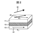
- the basic configuration of the GMR element is shown in FIG.
- the GMR element has a first magnetic layer (pinned magnetic layer or pinned magnetic layer) 13 and a second magnetic layer (free magnetic layer) 11, and a nonmagnetic layer (spacer layer) between the two magnetic layers. ) 12 is sandwiched.
- an external magnetic field 30 is applied to the GMR element, the magnetization direction of the fixed magnetic layer remains unchanged and fixed, while the magnetization direction 20 of the free magnetic layer changes according to the direction of the external magnetic field.
- the angle of the magnetization direction 22 of the pinned magnetic layer is referred to as a pin angle and is represented by ⁇ p .
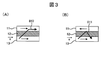
- FIG. 3 schematically shows cross sections of the free magnetic layer 11, the spacer layer 12, and the pinned magnetic layer 13. As shown in FIG. The arrows in the free magnetic layer 11 and the pinned magnetic layer 13 schematically indicate the direction of spin of many electrons.
- G / R is called a GMR coefficient and is several percent to several tens percent.
- the GMR element is also called a spin valve element because the current flow (that is, electric resistance) can be controlled by the direction of electron spin.
- the demagnetizing coefficient in the normal direction of the surface is extremely large, so the magnetization vector cannot rise in the normal direction (thickness direction), and in-plane Lying on. Since both the free magnetic layer 11 and the pinned magnetic layer 13 constituting the GMR element are sufficiently thin, the respective magnetization vectors lie in the in-plane direction.
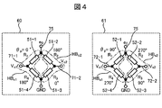
- the Wheatstone bridge 60 is configured by using four GMR elements R 1 (51-1) to R 4 (51-4).
- the difference voltage ⁇ V V c2 ⁇ V c1 between the terminals V c1 and V c2 when the excitation voltage e 0 is applied to the bridge circuit 60 of FIG. 4 is as follows:
- This bridge circuit is called a COS bridge because it outputs a signal proportional to cos ⁇ .
- the bridge 61 Since it is proportional to sin ⁇ , the bridge 61 is called a SIN bridge.
- the direction ⁇ m (magnetic field angle) of the magnetic field vector can be obtained.
- the magnetoresistive element is characterized by directly detecting the magnetic field direction.
- Patent Document 1 discloses a method of detecting an abnormality in a rotation angle sensor when the abnormality occurs.
- Patent Document 1 when the sum (V 1 + V 2 ) of the two outputs V 1 and V 2 of the bridge exceeds a predetermined range, it is determined that the sensor is faulty so that incorrect angle information is not output from the sensor. Take appropriate action. In this way, the safety of a vehicle or the like using the sensor can be improved.
- the digitization represented by “X-by-Wire” which operates only with electronic signals is also progressing.
- the command signal given by the driver with the steering wheel is once converted into an electronic signal (such as angle information). This is transmitted to the steering control device, and the steering drive motor is operated by the control according to the electronic signal.
- An object of the present invention is to provide a magnetic field angle measurement device or a rotation angle measurement device capable of outputting a measurement result capable of continuing the operation of the system even when an abnormality occurs in the sensor and contributing to downsizing of the system. is there.
- an angle signal is output based on a signal output from the normal half bridge.
- GMR element giant magnetoresistive element
- FIG. 1 is a configuration diagram of a magnetic field angle detection device according to the present embodiment.
- the magnetic field angle detection device includes a COS bridge 60, a SIN bridge 61, and a detection unit 302.
- the COS bridge 60 and the SIN bridge 61 are collectively referred to as an MR bridge unit 70.
- MR is an abbreviation for magneto-resistive element.
- the COS bridge 60 is composed of four GMR elements 51. By appropriately setting the spin direction (pin angle) of the fixed layer of the GMR element 51 as shown in FIG. V c2 ⁇ V c1 ) is proportional to the cosine cos ⁇ of the magnetic field angle ⁇ .
- the SIN bridge 61 includes four GMR elements 52. By appropriately setting the pin angle of the GMR element 52, the signal voltage (V s2 -V s1 ) of the bridge is changed to the magnetic field angle ⁇ . It is proportional to the sine sin ⁇ of.
- the one in which the bridge signal voltage (V c2 ⁇ V c1 ) is proportional to the cosine cos ⁇ of the magnetic field angle ⁇ is defined as the COS bridge 60, and the signal voltage (V s2 ⁇ V s1 ) is the sine sin ⁇ of the magnetic field angle ⁇ . What is proportional is defined as the SIN bridge 61.
- the reference angle of the magnetic field angle ⁇ is appropriately set so that the two signals are proportional to cos ⁇ and sin ⁇ , respectively.
- the COS bridge and the SIN bridge are defined as follows.
- a case where (V s2 ⁇ V s1 ) is proportional to the sine sin ( ⁇ eff ) of the effective magnetic field angle ⁇ eff is defined as a SIN bridge.
- the reference angle of the magnetic field angle is appropriately selected so that the two signals are proportional to cos ( ⁇ eff ) and sin ( ⁇ eff ).
- an AMR element is used will be described in detail in a later embodiment.
- the detection unit 302 receives the signal voltages V c1 , V c2 , V s1 , and V s2 of each bridge, and calculates and outputs the magnetic field angle ⁇ using these signals. During normal operation, the magnetic field angle is obtained using the relationship of (Equation 2) to (Equation 7).
- the excitation voltage e 0 was applied to the COS bridge 60 and the SIN bridge 61, and the other terminal was set to the ground potential (Ground potential, expressed as “GND” in the figure). This is the same connection as a normal bridge.
- the excitation voltage e 0 was set to 5 V in this example.
- connection between the MR bridge unit 70 and the detection unit 302 is not shown, but a power supply unit that supplies the excitation voltage e 0 is provided in the detection unit 302.
- the ground potential was also supplied from the detection unit 302 to both bridges.
- the connection between the excitation potential and the ground potential between the MR bridge unit 70 and the detection unit 302 is omitted, but the connection is appropriately performed as described above.
- the power supply unit that supplies the excitation voltage may use a constant current power supply instead of the constant voltage.
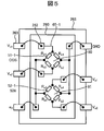
- FIG. 5 shows the configuration of the sensor element package 265 in which the GMR element bridge used in this embodiment is housed.
- a wafer 260 on which the GMR element 51 is formed is accommodated.
- a COS bridge 60 and a SIN bridge 61 are formed on the wafer 260.
- Each bridge constitutes a Wheatstone bridge using four GMR elements 51 and 52.
- the pads 262 on the wafer 260 and the corresponding terminals of the sensor element package 265 are connected by wire bonding.
- the wiring pattern of the GMR element 52 has a wiring width / length ratio (aspect ratio) set to have a desired resistance value.
- the magnetic field angle ⁇ is obtained.
- the magnetic field angle ⁇ is output to the outside through the output terminal 90 as an angle output.
- atan2 (y, x) ArcTan (y / x)
- atan2 (y, x) ArcTan (y / x) +180 °.
- fault and “failure” are used as follows.
- fault represents a state in which the characteristics of the internal state of the system exceed the normal allowable value.
- “Failure” refers to a situation where the system is unable to perform its functions continuously.
- the system refers to a magnetic field angle measurement device, a rotation angle measurement device, a rotating machine using the same, a vehicle drive device, or the like.
- the term “function stop” is also used in the same meaning as “failure” defined above.
- the factors that cause abnormalities in GMR elements are described.
- the cause of failure of the GMR element is a local resistance increase. This is because the GMR element is composed of a thin film having a thickness of several nanometers (nanometers), and therefore, when an excessive current flows, a part of the GMR element may be lost.
- FIG. 6 schematically shows one of the four GMR elements 52 constituting the bridge.
- the wiring that is the GMR element 52 includes the free magnetic layer 11, the spacer layer 12, and the fixed magnetic layer 13, as described with reference to FIG.
- (A) is the GMR element 52 in a normal state, and an arrow indicates a direction in which a current flows.
- (B) is a GMR element 52 in which a part of the pattern is narrowed due to a defect, and the defect part 53 (thinned part) in the current path is increased in resistance.
- the cause of the increase in resistance is that the cross-sectional area of the wiring is reduced and the resistance is increased because the resistance is reduced due to the defect. In other words, this is because the bulk resistance value locally increases in the narrowed portion (the missing portion 53).
- the magnetoresistive effect is caused by scattering at the free magnetic layer 11-spacer layer 12 interface and the fixed magnetic layer 13-spacer layer 12 interface in the entire wiring 52, as described with reference to FIG.
- the resistance component that increases due to wiring loss is a component that does not depend on the magnetic field direction. So, formulating the rate of increase of the magnetic field direction independent term as b times:
- Another cause of failure is deterioration of wire bonding.
- the connection of a wire connecting the V s1 terminal 263 and the wafer pad 262 in FIG. 5 deteriorates and a connection failure occurs, the signal voltage at the V s1 terminal of the sensor element package 265 becomes indefinite.
- the COS bridge 60 is constituted by two half bridges of the first half bridge HB c1 and the second half bridge HB c2 .
- the first half bridge HB c1 is composed of a GMR element R 1 (51-1), a signal output V c1 , and a GMR element R 4 (51-4).
- the second half bridge HB c2 is, GMR element R 2 (51-2), constituted by the signal output V c2, GMR element R 3 (51-3).
- the SIN bridge 61 is considered to be composed of the first half bridge HB s1 and the second half bridge HB s2 .
- the first half-bridge HB s1 is composed of a GMR element R 1 (52-1), the signal output V s1, GMR element R 4 (52-4).
- the second half bridge HB s2 includes a GMR element R 2 (52-2), a signal output V s2 , and a GMR element R 3 (52-3).
- the magnetic field angle ⁇ is obtained using the signal of the normal half bridge. More specifically, when an abnormality occurs in the half bridge HB s1 , the magnetic field angle is obtained using the output signal V s2 of the normal half bridge HB s2 .
- the magnetic field angle is obtained using the output signal of the normal half bridge.
- the magnetic field angle ⁇ obtained in this way is output from the detector.
- the detection unit 302 of the magnetic field angle measurement device 80 of the present invention can continue to output the correct magnetic field angle ⁇ even when an abnormality occurs in the GMR element. For this reason, the host system incorporating the magnetic field angle measurement device can be continued without stopping the operation.
- the magnetic field angle ⁇ may be calculated as follows. Further, when an abnormality occurs in the GMR element of the COS bridge 60, the correct magnetic field angle ⁇ can be obtained in the same manner.
- the operation state of the magnetic field angle measurement apparatus 80 that calculates the magnetic field angle using the normal half-bridge output signal is referred to as a “backup operation mode”.
- the COS bridge 60 and the SIN bridge 61 are not abnormal, and the operation state in which the magnetic field angle is calculated using the signals ⁇ V c21 and ⁇ V s21 is referred to as “normal operation mode”.
- the measured value V s2 is doubled as can be seen from (Equation 12). Therefore, the noise included in the measurement value is also doubled, so that the S / N ratio of the measurement value is reduced as compared with the normal operation mode. For this reason, the magnetic field angle ⁇ may have a slightly lower measurement accuracy than in the normal operation mode. As described above, in the backup operation mode, the measurement accuracy may deteriorate, but the correct magnetic field angle ⁇ is output.
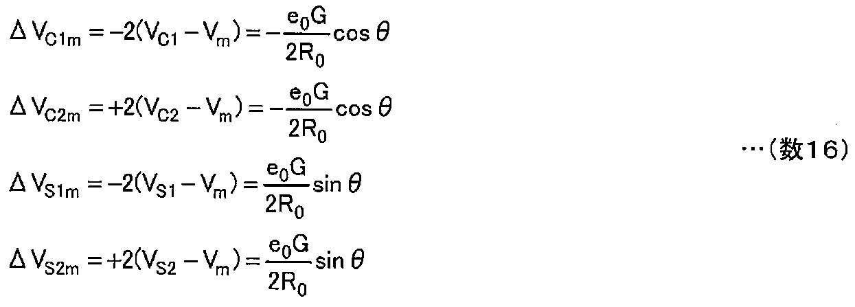
- the difference signal between the output voltage V c1 , V c2 , V s1 , V s2 of each half bridge and the intermediate voltage V m is doubled or -2 times as follows. Define as follows.
- the amount defined by (Equation 16) is appropriately set with the polarity of the coefficient ⁇ 2 so that each value becomes the same value as the differential signal ⁇ V c21 or ⁇ V s21 when normal.
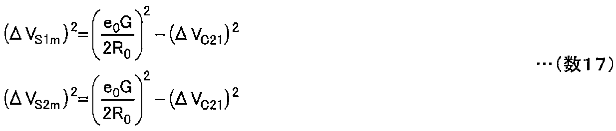
- Equation 17 is valid only when the half bridge is operating normally. Therefore, it can be identified that an abnormality has occurred in the herb bridge in which the relational expression (Equation 17) does not hold.
- ⁇ Res (1) and ⁇ Res (2) are obtained corresponding to the signals ⁇ V s1m and ⁇ V s2m of the two half bridges constituting the SIN bridge 61.
- the residual amount ⁇ Res (j) is obtained by doubling the square of the normal bridge signal voltage ( ⁇ V c21 ) and the difference between the half bridge signal voltage of the other bridge and the intermediate voltage V m ( ⁇ V sjm ). Is the sum of the squared and subtracted from the constant value. The one where the absolute value of the residual amount is larger is determined as the abnormality occurrence location.
- the magnetic field angle detection device of this embodiment includes a redundancy unit 311 in the detection unit 302.
- the configuration of the redundancy unit 311 is shown in FIG.
- Redundancy unit 311 inputs the output signal V q1 of the first half-bridge 65-1 (HB q1) output signal V q2 of the second half-bridge 65-2 (HB q2), and the intermediate voltage V m .
- q c or s, which are subscripts corresponding to the COS bridge 60 and the SIN bridge 61, respectively.
- the subscript “q” is used in this sense.
- Intermediate voltage V m is 1/2 of the excitation voltage e 0, equal to e 0/2.
- the generation circuit for the intermediate voltage V m is preferably a ratiometric circuit based on the excitation voltage e 0 .
- the ratiometric even if the excitation voltage e 0 is changed, generates voltage V m which means the circuit is kept to a constant ratio of e 0. The effect of making the V m generation circuit ratiometric will be described later.
- the intermediate voltage V m is generated by dividing the excitation voltage e 0 by resistors R 1 (331-1) and R 2 (331-2).
- the resistance values of the resistors R 1 (331-1) and R 2 (331-2) are made equal.
- a circuit that generates the intermediate voltage V m (resistors R 1 and R 2 (331-1, 331-2) in FIG. 7) may be provided in the detection unit 302.
- a power supply unit that generates the excitation voltage e 0 is provided separately from the detection unit 302, an intermediate voltage generation circuit may be provided in the power supply unit.
- the redundancy unit 311 When these signals are input, the redundancy unit 311 outputs output signals ⁇ V q21 , ⁇ V q1m , ⁇ V q2m , and an abnormality detection signal FD q .
- ⁇ V q21 is a quantity defined by ( Equation 8)
- ⁇ V q1m and ⁇ V q2m are quantities defined by ( Equation 16).
- the abnormality detection signal FD q generates an abnormality detection signal by inputting a difference output between ⁇ V q1m and ⁇ V q2m to the abnormality determination unit. Since ( ⁇ V q1m ⁇ V q2m ) is 0 during normal operation, the abnormality determination unit generates an abnormality detection signal when a certain threshold value is exceeded by a comparator circuit.
- the configuration of the redundancy unit 311 of this embodiment has the following two points.
- the differential signal between the half-bridge output signal and the intermediate voltage V m is amplified.
- the intermediate voltage V m generation circuit is ratiometric as described above, the ratio of e 0 and V m is kept constant even when the excitation voltage e 0 varies.
- any of the signals ⁇ V q21 , ⁇ V q1m , and ⁇ V q2m is proportional to the excitation voltage e 0 .
- the ratio of these signals is taken. Therefore, even if the excitation voltage e 0 varies, the value of the magnetic field angle ⁇ is not affected.
- the differential signal between the output signal of the half bridge and the intermediate voltage V m there is an effect that the influence on the output signal is reduced even if the excitation voltage varies.
- the detection unit 302 includes a redundancy unit 311-1 for inputting the output signal of the COS bridge 60 and a redundancy unit 311-2 for inputting the output signal of the SIN bridge 61.
- the output signal of each redundancy unit is input to the signal processing unit 303.
- a microcomputer is used as the signal processing unit 303, but the present invention is not limited to this.
- Signals input to the signal processing unit 303 are ⁇ V c21 , ⁇ V c1m , ⁇ V c2m , FD c and ⁇ V s21 , ⁇ V s1m , ⁇ V s2m , FD s . Therefore, by using these signals, an abnormal part can be identified by the same method as in the first embodiment, and a correct magnetic field angle ⁇ can be output even when an abnormality occurs.
- the correct magnetic field angle ⁇ can be output by the following method.
- the abnormality detection signals FD c and FD s of the COS bridge 60 and the SIN bridge 61 are transmitted, and it can be detected that an abnormality has occurred in the two bridges.
- the correct half bridge is identified in each of the bridges 60 and 61, and the correct magnetic field angle ⁇ is obtained as follows.
- a magnetic field angle detection apparatus according to the third embodiment of the present invention will be described with reference to FIG.
- FIG. 9 shows the configuration of the detector in this example.
- the output signals of the redundancy unit 311-1 and the redundancy unit 311-2 are input to the changeover switches 313-1 (SW1) and 313-2 (SW2), respectively.
- SW1 and SW2 changeover switches 313-1 and 313-2 (SW2), respectively.
- ADC analog-digital converter
- ADC Analog-Digital Converter
- the selector switch SW1 (313-1) is connected to the position 1a, and the selector switch SW2 (313-2) is connected to the position 2a.
- ⁇ V c21 and ⁇ V s21 are input to the signal processing unit 303, so the magnetic field angle ⁇ is obtained according to (Equation 9) and output as the magnetic field angle signal ⁇ .
- the output magnetic field angle signal may be either a digital signal or an analog signal.
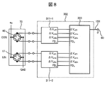
- FIG. 10A shows the operation of the changeover switch 313 when an abnormality occurs in the SIN bridge 61.
- the changeover switch SW1 (313-1) is set to 1d, and SW2 (313-2) is set to 2b.
- the selector switch 313 is set to the position (iii) or (iv) in FIG.
- the changeover switch 313 is switched according to FIG.
- the residual amount ⁇ res2 (i, j) defined by the equation (20) is calculated, and a normal half bridge is converted into COS, Find each in the SIN bridge.
- a normal combination is found, it is set to any one of (ii) to (v), and the correct magnetic field angle ⁇ is calculated using equation (19).
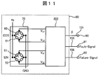
- a magnetic field angle measuring device 80 of the fourth embodiment using the present invention will be described with reference to FIG.
- the detection unit 302 outputs the magnetic field angle ⁇ , and outputs the abnormality transmission signal 155 and the stop transmission signal 156 to the output terminals 91 and 92, respectively.
- the abnormality transmission signal 155 (Fault Signal) is a signal for transmitting that the occurrence of an abnormality is detected in the magnetic field angle measuring apparatus but the correct angle ⁇ is output by operating in the backup operation mode.
- the stop transmission signal 156 (Failure Signal) indicates that the correct angle is not output because the degree of abnormality in the magnetic field angle measuring device is serious, that is, the function as the magnetic field angle measuring device is stopped. It is a signal to notify.
- the case where the stop transmission signal 156 is issued is, for example, when both of the two half bridges forming the COS bridge 60 become abnormal.
- an abnormality in the magnetic field angle measuring device is detected by the same method as in the first embodiment, and the mode is shifted to the backup operation mode. During operation in the backup operation mode, an abnormality transmission signal 155 is issued.
- the abnormality transmission signal 155 and the stop transmission signal 156 are output at different output terminals.
- the abnormality transmission signal 155 and the stop transmission signal 156 may be combined into one signal line.
- a specific method example to be combined into one a method of transmitting two kinds of signal states by preparing a plurality of signal voltage levels, or an abnormal transmission signal 155 and a stop transmission signal 156 using a digital signal, respectively. There is a method to output an error code corresponding to.
- the angle output 151, the abnormality transmission signal 155, and the stop transmission signal 156 may be combined into one signal line.
- two types of error code signals that can be distinguished from the digital signal representing the angle ⁇ are determined in advance, and the error codes may be assigned to the abnormality transmission signal 155 and the stop transmission signal 156.
- the abnormality transmission signal and angle output are output in the form of 16-bit digital data.
- the configuration of this digital data is shown in FIG.
- This data includes the angle information 591 in the first to twelfth bits, the stop transmission signal 592 in the 15th bit, and the abnormality transmission signal 593 in the 16th bit.
- Data having this data structure is output from the detection unit 302 of the magnetic field angle measurement device 80. In this way, the system that has received this data can know whether the magnetic field angle measuring device is operating in the normal mode or the backup operation mode, along with information on the magnetic field angle ⁇ .
- a low-cost magnetic field angle measuring device can be realized by reducing the number of output signal lines. Furthermore, noise tolerance can be increased by outputting a signal as digital data.
- the data receiving side can simultaneously know the measurement quality of the angle signal 591. There is an effect that appropriate processing can be performed.
- the signal having the data structure shown in FIG. 19 is transmitted by serial communication.
- the data of FIG. 19 can be transmitted in 1 ⁇ s with a transmission clock frequency of 16 MHz.
- the angle signal 591 and the abnormality transmission signal 593 can be transmitted substantially simultaneously.
- the host system incorporating the magnetic field angle measurement device can grasp the operation state of the magnetic field angle measurement device, and therefore can take measures according to the operation state.
- the specific treatment differs depending on the system in which the magnetic field angle measurement device is used. For example, during operation in the backup operation mode, it is possible to perform a treatment for improving safety by limiting the function and performance of the system.
- FIG. 20 is a diagram showing an example of the package configuration of the magnetic field angle measuring device 80 having the configuration of FIG. 1 or the configuration of FIG.
- the MR bridge unit 70 contains a COS bridge 60 and a SIN bridge 61. There are six wirings between the MR bridge unit 70 and the detection unit 302.
- the configuration includes two excitation voltages e 0 and ground potential GND, and four half-bridge output signals (V c1 , V c2 , V s1 , V s2 ).
- Output signals from the detection unit 302 are a magnetic field angle output 151 and an abnormal transmission signal output 155. As shown in FIG. 19, the magnetic field angle output 151 and the abnormality transmission signal output 155 may be combined into a single piece of data in the form of digital data and output through a single signal line.
- the detection unit 302 includes a power supply voltage terminal (V cc ) supplied from the outside and a ground potential terminal.
- the internal configuration of the configuration of FIG. 20 is the configuration of FIG.
- the MR bridge unit 70 and the detection unit 302 are each molded with a material such as resin.
- the wiring between the MR bridge and the detection unit 302 may be disconnected due to a stress or residual stress in the mold part.
- the correct magnetic field angle is not output.
- the magnetic field angle is calculated by using the half-bridge output signal that is not disconnected. The correct magnetic field angle ⁇ is output.
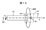
- a rotation angle measuring device 82 will be described with reference to FIG.
- the rotation angle measuring device 82 includes a sensor magnet 202 that is a magnetic flux generator and a magnetic field angle measuring device 80.
- the sensor magnet 202 is installed on the rotating body 121, and the rotating body 121 rotates around the rotation center line 226.
- the sensor magnet 202 Since the sensor magnet 202 is a magnetic flux generator, it generates a magnetic field in the direction shown in FIG. When the rotating body 121 rotates, the magnetic field direction at the position of the magnetic field angle measuring device 80 also rotates. Therefore, the rotation angle ⁇ r of the rotating body 121 can be measured by measuring the magnetic field angle.
- the magnetic field angle measuring device 80 used in the present embodiment has the same configuration as the magnetic field angle measuring device 80 of the first embodiment. Thus, even if abnormality occurs in one of the half-bridge of a magnetoresistive element included in the rotation angle measurement device 82, but measurement accuracy is slightly reduced as compared to normal, resulting correct rotation angle theta r . Therefore, there is an effect that the function of the host system including the rotation angle measuring device 82 can be continued.
- the rotating machine includes a motor and a generator.
- the motor will be described as an example.
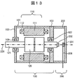
- FIG. 13 shows a cross-sectional view of the rotating machine of this embodiment.
- the motor unit 100 and the rotation angle detection unit 200 are configured.
- the motor unit 100 generates rotational torque by rotating a plurality of rotating magnetic poles by a magnetic action of a plurality of fixed magnetic poles and a plurality of rotating magnetic poles, and includes a stator 110 and a plurality of stators constituting the plurality of fixed magnetic poles. It is comprised from the rotor 120 which comprises this rotating magnetic pole.
- the stator 110 includes a stator core 111 and a stator coil 112 attached to the stator core 111.
- the rotor 120 is opposed to the inner peripheral side of the stator 110 via a gap and is rotatably supported.
- a three-phase AC type surface magnet type synchronous motor is used as the motor 100.
- the housing includes a cylindrical frame 101 and a first bracket 102 and a second bracket 103 provided at both axial ends of the frame 101.
- a bearing 106 is provided in the hollow portion of the first bracket 101, and a bearing 107 is provided in the hollow portion of the second bracket 103. These bearings support the rotating shaft 121 so as to be rotatable.
- a seal member (not shown) is provided between the frame 101 and the first bracket 102.
- the seal member is an O-ring provided in an annular shape, and is sandwiched and compressed by the frame 101 and the first bracket 102 from the axial direction and the radial direction. Thereby, between the flame
- the space between the frame 101 and the second bracket 103 is also waterproofed by a seal member (not shown).
- the stator 110 includes a stator core 111 and a stator coil 112 attached to the stator core 111, and is installed on the inner peripheral surface of the frame 101.
- the stator core 111 is a magnetic body (magnetic path forming body) formed by laminating a plurality of silicon steel plates in the axial direction.
- the stator core 111 protrudes inward in the radial direction from the annular back core and the inner peripheral portion of the back core. It consists of a plurality of teeth arranged at equal intervals in the direction.
- a winding conductor constituting the stator coil 112 is intensively wound around each of the plurality of teeth.
- the plurality of winding conductors are electrically connected for each phase by a connecting member juxtaposed in the axial end of one coil end portion (on the second bracket 103 side) of the stator coil 112, and further, a three-phase winding.
- Three-phase winding connection methods include a ⁇ (delta) connection method and a Y (star) connection method. In this embodiment, a ⁇ (delta) connection method is adopted.
- the rotor 120 includes a rotor core fixed on the outer peripheral surface of the rotating shaft 121, a plurality of magnets fixed on the outer peripheral surface of the rotor core, and a magnet cover provided on the outer peripheral side of the magnet.
- the magnet cover is for preventing scattering of the magnet from the rotor core, and is a cylindrical member or a tubular member formed of a non-magnetic material such as stainless steel (popular name SUS).
- the rotation angle detector 200 includes a magnetic field angle measurement device 201 (hereinafter referred to as a magnetic field sensor module 201) and a sensor magnet 202.
- the rotation angle detection unit 200 is installed in a space surrounded by the housing 203 and the second bracket 103.
- the sensor magnet 202 is installed on a shaft that rotates in conjunction with the rotating shaft 121. When the rotating shaft 121 changes its rotational position, the direction of the magnetic field generated changes accordingly. By detecting this magnetic field direction with the magnetic field sensor module 201, the rotation angle (rotation position) of the rotating shaft 121 can be measured.
- the sensor magnet 202 is a two-pole magnet magnetized with two poles, or a multi-pole magnet magnetized with four or more poles.
- the magnetic field sensor module used the magnetic angle measuring device 80 described in Example 4 of the present invention.
- the magnetic field sensor module 201 is installed in the housing 203.
- the housing 203 is preferably made of a material having an absolute value of magnetic susceptibility of 0.1 or less, such as aluminum or resin, so as not to affect the direction of magnetic flux. In this embodiment, it is made of resin.
- the magnetic field sensor module 201 may be fixed to the motor unit, and may be fixed to components other than the housing 203. If fixed to the motor unit, when the rotation angle of the rotating shaft 121 changes and the direction of the sensor magnet 202 changes, the rotation of the rotating shaft 121 is detected by detecting the change in the magnetic field direction at the magnetic field sensor 201 unit. This is because the corner can be detected.
- the sensor wiring 208 is connected to the magnetic field sensor module 201. An output signal of the magnetic field sensor 201 is transmitted by the sensor wiring 208.
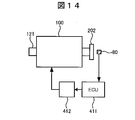
- the output signal of the magnetic field angle measuring device 80 is input to a rotating machine control controller (rotating machine control ECU) 411.
- a rotating machine control controller rotating machine control ECU
- These three types of signals may be transmitted individually using three signal lines, or as described above, for example, in the form of digital signals, transmitted in a time-sharing manner on one signal line. May be.
- the signal input to the rotating machine controller may be only the rotation angle ⁇ signal.
- the rotating machine controller calculates an appropriate driving voltage to be applied to the rotating machine based on the inputted rotation angle ⁇ , outputs a signal to the rotating machine drive unit 412, and is output from the rotating machine drive unit 412.
- the rotating machine 100 is driven by the drive waveform.
- the rotating machine controller even when an abnormality occurs in a part of the half bridges of the MR bridge unit 70 constituting the magnetic field angle measuring device 80, the correct angle is input to the rotating machine controller by shifting to the backup operation mode. Therefore, the rotating machine has an effect that its functional operation can be continued.
- an abnormal transmission signal is input to the rotating machine controller.
- the rotating machine control controller transmits an abnormality transmission signal to a host system in which the rotating machine is incorporated.
- the host system can take appropriate measures such as limiting the function of the system based on the abnormality transmission signal transmitted from the rotating machine.
- FIG. 14 shows a configuration in which the MR bridge unit 70 and the detection unit 302 are arranged in the vicinity of the sensor magnet 202 by being arranged inside the magnetic field angle measuring device 80, but the present embodiment has this configuration. It is not limited.
- the signal processing unit 303 in the detection unit 302 may be disposed in the vicinity of the rotating machine control controller, or the signal processing unit 303 may be incorporated in the rotating machine control controller.
- the signal processing unit 303 is configured by a microcomputer, the number of microcomputers to be used can be reduced by incorporating the function of the signal processing unit 303 into the rotating machine control controller, so that there is an effect that a low-cost rotating machine can be realized.
- FIGS. 13 and 14 an example of a motor as a rotating machine is shown.
- rotor includes not only a motor but also a “generator”, that is, a machine that converts mechanical energy into electrical energy. Even in the case of a generator, the effects of the present invention can be obtained with the same configuration as in FIGS. 13 and 14.
- FIG. 15 shows an example of electric power steering (abbreviated as Electric Power-Assisted Steeling, EPS) as a seventh embodiment according to the present invention.
- EPS Electric Power-Assisted Steeling
- the steering shaft 503 mechanically connected to the handle 501 moves in conjunction with the rotary shaft 121 via a connecting portion 504 formed of a gear or the like.
- the rotating shaft 121 is a rotating shaft of the motor 100, and the sensor magnet 202 is installed at one end.
- a magnetic field angle measurement device 80 (hereinafter referred to as a magnetic field sensor module 201) is installed in the vicinity of the sensor magnet 202, and measures the rotation angle of the rotary shaft 121 and transmits it to the ECU 411.
- the ECU 411 calculates an appropriate motor drive amount from a signal from a torque sensor (not shown) installed in the steering column 502 and a rotation angle signal ⁇ from the magnetic field sensor module 201 to drive the motor.
- the signal is transmitted to the unit 412.
- the motor 100 assists the movement of the steering shaft 503 via the rotating shaft 121.
- the magnetic field angle measuring device described in the fourth embodiment of the present invention is used as the magnetic field angle measuring device 80.
- the correct magnetic field angle rotation angle
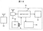
- a vehicle 580 according to the eighth embodiment using the present invention will be described with reference to FIG.
- This embodiment is a vehicle 580 using an electric power steering system.
- the magnetic field angle measuring device 80 used in the electric power steering is the rotation angle measuring device according to the fourth embodiment of the present invention.
- the abnormality transfer signal is issued by shifting to the backup operation mode depending on the type of abnormality.
- a stop transmission signal is issued in the case of an abnormality in which the backup operation mode is impossible.
- This stop transmission signal is transmitted to the host system 581 of the electric power steering system (EPS system) 582.
- EPS system electric power steering system
- it may be transmitted to the host system 581 via the electronic control unit (ECU) of the electric power steering system (EPS system) 582.
- ECU electronice control unit
- the information may be transmitted to the upper system 581 via a system layer other than the EPS system 582.
- the host system 581 When the abnormality transmission signal is transmitted to the host system 581, the host system 581 performs all or some combination of the following operations.
- an abnormality is displayed on the driver's seat display system 584, or the driver is informed that an abnormality has occurred due to a sound such as an alarm bell.
- the vehicle 580 can operate, but instructs the driver to go to a vehicle repair station or the like as soon as possible.
- the host system 581 shifts to the function restriction mode.
- functions such as limiting the maximum speed of the vehicle 580 are limited to increase safety and provide the necessary operations to move to the repair station.
- the vehicle drive system 586 is functionally limited to limit the maximum speed.
- the host system 581 transmits an abnormality occurrence to the vehicle repair station 588 using the wireless transmission system 585.
- the vehicle repair station 588 can quickly repair the vehicle when the vehicle arrives. If the vehicle does not come in for repair after a certain period of time, the vehicle owner can be urged to repair.
- the function for moving to the vehicle repair station is provided. Improve safety by limiting performance and functions such as speed.
- a ninth embodiment of the present invention will be described with reference to FIG.
- a present Example is an example of the hybrid vehicle drive device using a rotation angle measuring device.
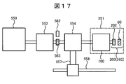
- FIG. 17 is a schematic diagram of a hybrid vehicle drive device combining an internal combustion engine and an electric motor as power for the vehicle.
- the output rotation shaft of the engine 553, the generator 552, and the drive motor 551 are arranged on the same axis, and the power is appropriately transmitted by the function of the power distribution mechanism 554.
- the power distribution method is appropriately set based on information such as the vehicle running state, the acceleration command state, and the battery charging state. Further, a power coupling mechanism 557 for transmitting power from the power distribution mechanism 554 to the power shaft 558 is provided.
- the drive motor 551 As the drive motor 551, the rotating machine described in Example 6 of the present invention was used.
- the drive motor 551 includes the motor unit 100 and the rotation angle detection unit 200 as described in the sixth embodiment.
- the rotation angle detection unit 200 constitutes a drive motor rotation angle sensor 560 that detects the rotation angle of the drive motor 551.
- the generator 552 is provided with a generator rotation angle sensor 562.
- a sensor magnet 563 is installed on the rotating shaft of the generator, and the direction of the magnetic field generated by the sensor magnet 563 is measured by the generator rotation angle sensor 562.
- the generator rotation angle sensor 562 the magnetic field angle measuring device described in the first embodiment was used.
- the correct rotation angle ⁇ is output by using the normal half bridge. It becomes possible to operate with. This has the effect of preventing the entire vehicle from stopping.
- the host system When the host system receives an abnormal transmission signal, it takes safety measures by limiting the maximum speed of the vehicle. Furthermore, there is an effect that it is possible to take measures such as prompt repair by issuing an alarm for notifying the driver of an abnormal state or notifying the abnormality by communication to the vehicle repair station.
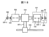
- FIG. 18 is a schematic diagram of an electric vehicle driving apparatus using a power electric motor of an automobile.
- the drive motor 551 and the generator 552 are arranged on the same axis, and the power is appropriately transmitted by the function of the power distribution mechanism 554.
- the power distribution method is appropriately set based on information such as the vehicle running state, the acceleration command state, and the battery charge state.
- the drive motor 511 As the drive motor 511, the rotating machine described in Example 6 of the present invention was used.
- the drive motor 511 includes the motor unit 100 and the rotation angle detection unit 200 as described in the sixth embodiment.
- the generator 552 is provided with a generator rotation angle sensor 562.
- a sensor magnet 563 is installed on the rotating shaft of the generator, and the direction of the magnetic field generated by the sensor magnet 563 is measured by the generator rotation angle sensor 562.
- the generator rotation angle sensor 562 the magnetic field angle measuring device described in the first embodiment was used.
- the correct rotation angle ⁇ is output by using the normal half bridge. It becomes possible to operate with. This has the effect of preventing the entire vehicle from stopping.
- the present invention is not limited to the GMR element, but can be applied to other magnetoresistive elements.
- an example using an anisotropic magnetoresistive element (Anisotropic-Magneto-resistance, AMR element) will be described.
- the reference angle of the magnetic field angle ⁇ is set to the current direction ⁇ .
- the current direction ⁇ can be set by the pattern shape of the wiring.
- the signal output of the bridge circuit composed of AMR elements is such that the COS bridge 60 is proportional to cos ( ⁇ eff ) and the SIN bridge 61 is proportional to sin ( ⁇ eff ).
- a bridge that outputs a signal proportional to the cosine cos ( ⁇ eff ) of the effective magnetic field angle ⁇ eff is a COS bridge.
- a bridge that outputs a signal proportional to the sine sin ( ⁇ eff ) of the effective magnetic field angle ⁇ eff is defined as a SIN bridge 61.
- the reference angle of the magnetic field angle is appropriately selected so that the two signals are proportional to cos ( ⁇ eff ) and sin ( ⁇ eff ).
- the shape substantially corresponds to the equations (Equation 8) and (Equation 9) of the bridge circuit of the GMR element.
- the magnetic field angle ⁇ is obtained as follows.
Landscapes
- Engineering & Computer Science (AREA)
- Physics & Mathematics (AREA)
- General Physics & Mathematics (AREA)
- Chemical & Material Sciences (AREA)
- Combustion & Propulsion (AREA)
- Transportation (AREA)
- Mechanical Engineering (AREA)
- Microelectronics & Electronic Packaging (AREA)
- Power Engineering (AREA)
- Transmission And Conversion Of Sensor Element Output (AREA)
- Power Steering Mechanism (AREA)
- Measuring Magnetic Variables (AREA)
Abstract
Description







ΔVc21=Vc2-Vc1 ΔVs21=Vs2-Vs1とすると、(数5),(数6)より次式を得る:

















53 欠損部
60 COSブリッジ
61 SINブリッジ
65 ハーフブリッジ
70 MRブリッジ部
71,72 ハーフブリッジ出力端子
80 磁界角計測装置
82 回転角計測装置
100 モータ部
110 ステータ
111 ステータコア
112 ステータコイル
120 ロータ
121 回転体
151 角度出力
155 異常伝達信号
156 停止伝達信号
200 回転角検出部
202 センサ磁石
226 回転中心線
260 ウエハ
262 ウエハ・パッド
265 センサ素子パッケージ
302 検出部
303 信号処理部
311 冗長化部
313 切替スイッチ
331 抵抗
411 電子制御コントロールユニット
412 駆動部
501 ハンドル
502 ステアリング・コラム
503 ステアリング・シャフト
504 連結部
551 駆動モータ
552 発電機
553 エンジン
554 動力分配機構
557 動力結合機構
558 動力シャフト
560 駆動モータ回転角センサ
562 発電機磁界角センサ
563 センサ磁石
580 車両
581 上位システム
582 EPSシステム
583 車両駆動システム
584 運転席表示システム
585 無線発信システム
588 車両修理ステーション
591 角度情報データ
592 停止信号データ
593 異常信号データ
本明細書で引用した全ての刊行物、特許および特許出願をそのまま参考として本明細書にとり入れるものとする。
Claims (22)
- 磁気抵抗素子で構成されるCOSブリッジと、SINブリッジと、検出部とで構成される磁界角度計測装置であって、
前記検出部は、COSブリッジまたはSINブリッジのおのおのの、いずれか一方のハーフブリッジに異常が発生した場合に、正常な方のハーフブリッジから出される信号に基づいて角度信号を出力する磁界角計測装置。 - 請求項1に記載の磁界角計測装置において、正常なハーフブリッジを同定する手段を有する磁界角計測装置。
- 請求項2に記載の磁界角計測装置において、前記正常な方のハーフブリッジから出される信号に基づいて角度信号を出力する際に、前記検出部が異常伝達信号を出力する磁界角計測装置。
- 請求項3に記載の磁界角計測装置において、前記異常伝達信号とは別に停止伝達信号を有する磁界角計測装置。
- 請求項3に記載の磁界角計測装置において、前記異常伝達信号は、前記角度信号と同一の信号線を用いてデジタル信号で出力されることを特徴とする磁界角計測装置。
- 回転体に取り付けられた磁束発生体と、請求項1に記載の磁界角計測装置とを有する回転角計測装置であって、前記磁束発生体が生成する磁界の方向を計測することで前記回転体の回転角を計測する回転角計測装置。
- ロータとステータを有する回転機であって、前記ロータと連動して回転する磁束発生体と、請求項1に記載の磁界角計測装置とを有し、前記磁束発生体が発生する磁界の方向を前記磁界角計測装置で計測する回転機。
- 請求項3に記載の磁界角計測装置が組み込まれたシステムであって、前記システムは通常動作モードと機能制限モードとを有し、前記機能制限モードでは前記システムの機能の一部を制限するものであって、前記磁界角計測装置が前記異常伝達信号を出力した場合に、前記機能制限モードで動作するシステム。
- 請求項3に記載の磁界角計測装置を用いた車両であって、前記車両は通常動作モードと機能制限モードとを有し、前記磁界角計測装置が前記異常伝達信号を出力した場合に、前記機能制限モードで動作する車両。
- 請求項9に記載の車両であって、前記機能制限モードでの車両の最高速度が前記通常動作モードでの最高速度よりも小さいことを特徴とする車両。
- 請求項7に記載の回転機を有する車両駆動装置。
- 請求項7に記載の回転機をモータとして有する車両駆動装置であって、前記磁界角計測装置が前記正常な方のハーフブリッジから出される信号に基づいて角度信号を出力する際に、前記検出部が異常伝達信号を出力し、前記異常伝達信号が出力された際に前記モータの最高速度を制限する車両駆動装置。
- 発電機とモータとを有する車両駆動装置であって、前記発電機に請求項3に記載の磁界角計測装置が設置されており、前記磁界角計測装置が前記異常伝達信号を出力している場合には、前記発電機による回生ブレーキ機能を制限することを特徴とする車両駆動装置。
- 請求項1乃至5のいずれか1項に記載の磁界角計測装置であって、前記磁気抵抗素子は巨大磁気抵抗素子であることを特徴とする磁界角計測装置。
- 請求項1乃至5のいずれか1項に記載の磁界角計測装置であって、前記磁気抵抗素子は異方性磁気抵抗素子であることを特徴とする磁界角計測装置。
- 請求項1に記載の磁界角計測装置であって、前記検出部は前記ハーフブリッジの出力信号と、前記ハーフブリッジへの励起電圧の1/2の電圧である中間電圧との差動検出器を有することを特徴とする磁界角計測装置。
- 請求項1に記載の磁界角計測装置であって、前記異常が、前記一方のハーフブリッジと前記検出部との間の断線であることを特徴とする磁界角計測装置。
- 請求項2に記載の磁界角計測装置において、前記正常な方のハーフブリッジから出される信号に基づいて角度信号を出力する際に、前記検出部が異常伝達信号を出力する磁界角計測装置。
- 請求項18に記載の磁界角計測装置において、前記異常伝達信号とは別に停止伝達信号を有する磁界角計測装置。
- 請求項18に記載の磁界角計測装置において、前記異常伝達信号は、前記角度信号と同一の信号線を用いてデジタル信号で出力されることを特徴とする磁界角計測装置。
- 請求項16に記載の磁界角計測装置であって、前記中間電圧は前記励起電圧からレシオメトリックな回路で生成することを特徴とする磁界角計測装置。
- 磁気抵抗素子で構成されるCOSブリッジと、SINブリッジと、検出部とで構成される磁界角度計測装置の角度算出方法であって、
前記検出部は、COSブリッジまたはSINブリッジのおのおのの、いずれか一方のハーフブリッジに異常が発生した場合に、正常な方のハーフブリッジから出される信号に基づいて角度信号を算出する磁界角計測装置の角度算出方法。
Priority Applications (3)
| Application Number | Priority Date | Filing Date | Title |
|---|---|---|---|
| DE112011104630T DE112011104630T5 (de) | 2010-12-28 | 2011-12-20 | Magnetfeld-Winkelmessvorrichtung, Drehwinkelmessvorrichtung und Rotationsmaschine, System, Fahrzeug und Fahrzeugantriebsvorrichtung, die jeweils dieselbe Drehwinkelmessvorrichtung verwenden |
| US13/992,935 US20130264915A1 (en) | 2010-12-28 | 2011-12-20 | Magnetic Field Angle Measurement Apparatus, Rotation Angle Measurement Apparatus, and Rotation Machine, System, Vehicle, and Vehicle Drive Apparatus Each Using Same Rotation Angle Measurement Apparatus |
| CN2011800636736A CN103282745A (zh) | 2010-12-28 | 2011-12-20 | 磁场角计测装置、旋转角计测装置和使用它的旋转机械、系统、车辆和车辆驱动装置 |
Applications Claiming Priority (2)
| Application Number | Priority Date | Filing Date | Title |
|---|---|---|---|
| JP2010-291545 | 2010-12-28 | ||
| JP2010291545A JP5380425B2 (ja) | 2010-12-28 | 2010-12-28 | 磁界角計測装置,回転角計測装置およびそれを用いた回転機,システム,車両および車両駆動装置 |
Publications (1)
| Publication Number | Publication Date |
|---|---|
| WO2012090768A1 true WO2012090768A1 (ja) | 2012-07-05 |
Family
ID=46382879
Family Applications (1)
| Application Number | Title | Priority Date | Filing Date |
|---|---|---|---|
| PCT/JP2011/079432 Ceased WO2012090768A1 (ja) | 2010-12-28 | 2011-12-20 | 磁界角計測装置,回転角計測装置およびそれを用いた回転機,システム,車両および車両駆動装置 |
Country Status (5)
| Country | Link |
|---|---|
| US (1) | US20130264915A1 (ja) |
| JP (1) | JP5380425B2 (ja) |
| CN (1) | CN103282745A (ja) |
| DE (1) | DE112011104630T5 (ja) |
| WO (1) | WO2012090768A1 (ja) |
Cited By (3)
| Publication number | Priority date | Publication date | Assignee | Title |
|---|---|---|---|---|
| US20150137797A1 (en) * | 2013-11-19 | 2015-05-21 | Infineon Technologies Ag | Off-axis magnetic field angle sensors |
| US9605978B2 (en) | 2013-11-19 | 2017-03-28 | Infineon Technologies Ag | Off-axis magnetic field angle sensors |
| TWI685667B (zh) * | 2019-03-18 | 2020-02-21 | 愛盛科技股份有限公司 | 磁場感測裝置 |
Families Citing this family (39)
| Publication number | Priority date | Publication date | Assignee | Title |
|---|---|---|---|---|
| DE112010005566B4 (de) | 2010-05-14 | 2018-05-09 | Hitachi, Ltd. | Magnetfeldwinkel-Messvorrichtung und Drehwinkel-Messvorrichtung, die diese verwendet |
| JP5427842B2 (ja) | 2011-06-30 | 2014-02-26 | 日立オートモティブシステムズ株式会社 | 回転角計測装置,制御装置およびそれらを用いた回転機システム |
| US9018942B2 (en) * | 2013-01-11 | 2015-04-28 | Bourns, Inc. | Position measurement using a variable flux collector |
| JP5948656B2 (ja) * | 2013-02-27 | 2016-07-06 | 日立オートモティブシステムズ株式会社 | 回転角検出装置 |
| JP2014181981A (ja) * | 2013-03-19 | 2014-09-29 | Denso Corp | 電流センサ |
| JP6239895B2 (ja) | 2013-08-08 | 2017-11-29 | 株式会社ジェイテクト | モータ制御装置及び電動パワーステアリング装置 |
| US9506996B2 (en) | 2013-10-17 | 2016-11-29 | Infineon Technologies Ag | Apparatus and method for detecting an error in a measurement of a quantity |
| US9915552B2 (en) * | 2013-11-19 | 2018-03-13 | Infineon Technologies Ag | Perpendicular gradiometric angle sensors, systems and methods |
| JP6419426B2 (ja) * | 2013-12-19 | 2018-11-07 | 日本電産エレシス株式会社 | 電動パワーステアリング用電子制御ユニット |
| JP6194372B2 (ja) | 2014-01-22 | 2017-09-06 | アルプス電気株式会社 | センサモジュール、並びに、これに用いるセンサチップ及び処理回路チップ |
| CN105899964B (zh) * | 2014-01-23 | 2019-09-24 | 三菱电机株式会社 | 磁检测装置 |
| JP5958572B2 (ja) * | 2014-02-27 | 2016-08-02 | 株式会社デンソー | 回転角検出装置、および、これを用いた電動パワーステアリング装置 |
| JP5967382B2 (ja) * | 2014-03-17 | 2016-08-10 | Tdk株式会社 | 回転磁界センサおよびそれを用いた角度決定方法 |
| EP2960666B1 (en) * | 2014-06-25 | 2017-01-25 | Nxp B.V. | Sensor system with a three half-bridge configuration |
| US9618365B2 (en) * | 2014-09-02 | 2017-04-11 | Infineon Technologies Ag | Angle sensor system having a magnetic sensor |
| JP6457243B2 (ja) | 2014-11-06 | 2019-01-23 | 株式会社東芝 | 電流センサ、及びスマートメータ |
| DE102014119531B4 (de) | 2014-12-23 | 2019-06-27 | Infineon Technologies Ag | Sensorschaltung |
| US9625281B2 (en) * | 2014-12-23 | 2017-04-18 | Infineon Technologies Ag | Fail-safe operation of an angle sensor with mixed bridges having separate power supplies |
| JP2016180727A (ja) * | 2015-03-25 | 2016-10-13 | セイコーエプソン株式会社 | 検出回路、半導体集積回路装置、磁界回転角検出装置、及び、電子機器 |
| JP6418063B2 (ja) * | 2015-05-20 | 2018-11-07 | 株式会社デンソー | センサ装置、これを用いた電動パワーステアリング装置、および、制御装置 |
| JP6591847B2 (ja) * | 2015-09-30 | 2019-10-16 | 旭化成エレクトロニクス株式会社 | センサ出力回路、装置、及び故障検出方法 |
| JP6555062B2 (ja) | 2015-10-01 | 2019-08-07 | 株式会社デンソー | 回転角検出装置 |
| DE102016103518B4 (de) * | 2016-02-29 | 2024-10-24 | Robert Bosch Gmbh | Verfahren und Vorrichtung zur Rotorlagendiagnose in einem elektromotorischen Antrieb |
| JP6535292B2 (ja) * | 2016-03-01 | 2019-06-26 | 旭化成エレクトロニクス株式会社 | 異常診断装置、異常診断方法、およびプログラム |
| WO2017186256A1 (de) * | 2016-04-29 | 2017-11-02 | Tdk-Micronas Gmbh | Abstandsmessvorrichtung |
| DE102017110197A1 (de) * | 2016-05-12 | 2017-11-16 | Infineon Technologies Ag | Außeraxiale Magnetfeld-Winkelsensoren |
| US20200318993A1 (en) * | 2016-07-01 | 2020-10-08 | Thyssenkrupp Presta Ag | Rotational position sensor with tunnel magnetoresistive sensor |
| DE102016121488B4 (de) * | 2016-11-10 | 2025-01-23 | Robert Bosch Gmbh | Verfahren zur detektion eines rotorlagewinkels in einer elektrischen maschine und steuerung dafür sowie damit ausgestattetes antriebssystem |
| CN108945086A (zh) * | 2017-05-19 | 2018-12-07 | 上海海拉电子有限公司 | 一种电动助力转向系统 |
| JP6906196B2 (ja) * | 2017-05-30 | 2021-07-21 | パナソニックIpマネジメント株式会社 | 電動工具 |
| EP4296623A3 (en) * | 2019-12-30 | 2024-03-13 | Melexis Technologies SA | Magnetic position sensor system and method |
| US11231297B2 (en) * | 2020-01-09 | 2022-01-25 | Robert Bosch Gmbh | Providing availability of rotary position sensor information after hardware failures |
| JP7229418B2 (ja) * | 2020-02-26 | 2023-02-27 | 三菱電機株式会社 | レゾルバの異常検出装置 |
| JP2021143969A (ja) * | 2020-03-13 | 2021-09-24 | Tdk株式会社 | 磁場検出装置、回転検出装置および電動パワーステアリング装置 |
| US11637482B2 (en) * | 2020-10-08 | 2023-04-25 | Analog Devices International Unlimited Company | Magnetic sensor system for motor control |
| JP7769964B2 (ja) * | 2021-05-17 | 2025-11-14 | パナソニックIpマネジメント株式会社 | 磁気センサ及び磁気検知システム |
| US12514656B2 (en) * | 2021-05-27 | 2026-01-06 | Covidien Lp | Surgical robotic systems |
| TWI874700B (zh) * | 2021-08-19 | 2025-03-01 | 達明機器人股份有限公司 | 位置偵測系統 |
| DE102021123737A1 (de) | 2021-09-14 | 2023-03-16 | Schaeffler Technologies AG & Co. KG | Sensoranordnung, Verfahren zur Detektion eines Signalfehlers in einer Sensoranordnung, Computerprogrammprodukt und Steuereinheit |
Citations (12)
| Publication number | Priority date | Publication date | Assignee | Title |
|---|---|---|---|---|
| JPH10201008A (ja) * | 1997-01-13 | 1998-07-31 | Mitsubishi Motors Corp | 電気自動車の回生制動装置 |
| JP2000088609A (ja) * | 1998-09-16 | 2000-03-31 | Daihatsu Motor Co Ltd | 操舵角検出装置 |
| JP2004212179A (ja) * | 2002-12-27 | 2004-07-29 | Koyo Seiko Co Ltd | 回転角検出装置 |
| JP2004358997A (ja) * | 2003-06-02 | 2004-12-24 | Toyota Motor Corp | 冗長型制御装置を備えた自動車 |
| JP2005233720A (ja) * | 2004-02-18 | 2005-09-02 | Fanuc Ltd | エンコーダ及び電動機の制御装置 |
| JP2006105932A (ja) * | 2004-10-08 | 2006-04-20 | Toyota Motor Corp | ブリッジ回路を有するセンサの故障判定装置およびその故障判定方法 |
| JP2006170837A (ja) * | 2004-12-16 | 2006-06-29 | Alps Electric Co Ltd | 補償機能を備えた角度検出センサ |
| JP2006317389A (ja) * | 2005-05-16 | 2006-11-24 | Tdk Corp | 角度スイッチセンサ |
| JP2008196938A (ja) * | 2007-02-13 | 2008-08-28 | Nsk Ltd | 回転情報算出装置 |
| JP2010048717A (ja) * | 2008-08-22 | 2010-03-04 | Tokai Rika Co Ltd | 位置検出装置 |
| JP2010185751A (ja) * | 2009-02-12 | 2010-08-26 | Nsk Ltd | 回転情報算出装置 |
| JP2011099846A (ja) * | 2009-10-09 | 2011-05-19 | Denso Corp | 回転角検出装置、および、これを用いた電動パワーステアリング装置 |
Family Cites Families (8)
| Publication number | Priority date | Publication date | Assignee | Title |
|---|---|---|---|---|
| DE19640695A1 (de) * | 1996-10-02 | 1998-04-09 | Bosch Gmbh Robert | Magnetoresistiver Sensor mit temperaturstabilem Nullpunkt |
| DE19852502A1 (de) * | 1998-11-13 | 2000-05-18 | Philips Corp Intellectual Pty | Verfahren zur Offset-Kalibrierung eines magnetoresistiven Winkelsensors |
| CN1330939C (zh) * | 2002-03-22 | 2007-08-08 | 旭化成电子材料元件株式会社 | 角度检测装置和角度检测系统 |
| JP2005049097A (ja) | 2003-07-29 | 2005-02-24 | Alps Electric Co Ltd | 故障検出回路 |
| JP2005051589A (ja) * | 2003-07-30 | 2005-02-24 | Matsushita Electric Ind Co Ltd | 車両無線データ収集システム |
| JP4991322B2 (ja) * | 2006-10-30 | 2012-08-01 | 日立オートモティブシステムズ株式会社 | Gmr素子を用いた変位センサ,gmr素子を用いた角度検出センサ及びそれらに用いる半導体装置 |
| JP5156671B2 (ja) * | 2009-02-27 | 2013-03-06 | 株式会社日立製作所 | 磁界検出装置および計測装置 |
| JP5287635B2 (ja) * | 2009-09-24 | 2013-09-11 | 株式会社ジェイテクト | 回転角センサ、モータ、回転角検出装置、及び電動パワーステアリング装置 |
-
2010
- 2010-12-28 JP JP2010291545A patent/JP5380425B2/ja not_active Expired - Fee Related
-
2011
- 2011-12-20 US US13/992,935 patent/US20130264915A1/en not_active Abandoned
- 2011-12-20 CN CN2011800636736A patent/CN103282745A/zh active Pending
- 2011-12-20 WO PCT/JP2011/079432 patent/WO2012090768A1/ja not_active Ceased
- 2011-12-20 DE DE112011104630T patent/DE112011104630T5/de not_active Ceased
Patent Citations (12)
| Publication number | Priority date | Publication date | Assignee | Title |
|---|---|---|---|---|
| JPH10201008A (ja) * | 1997-01-13 | 1998-07-31 | Mitsubishi Motors Corp | 電気自動車の回生制動装置 |
| JP2000088609A (ja) * | 1998-09-16 | 2000-03-31 | Daihatsu Motor Co Ltd | 操舵角検出装置 |
| JP2004212179A (ja) * | 2002-12-27 | 2004-07-29 | Koyo Seiko Co Ltd | 回転角検出装置 |
| JP2004358997A (ja) * | 2003-06-02 | 2004-12-24 | Toyota Motor Corp | 冗長型制御装置を備えた自動車 |
| JP2005233720A (ja) * | 2004-02-18 | 2005-09-02 | Fanuc Ltd | エンコーダ及び電動機の制御装置 |
| JP2006105932A (ja) * | 2004-10-08 | 2006-04-20 | Toyota Motor Corp | ブリッジ回路を有するセンサの故障判定装置およびその故障判定方法 |
| JP2006170837A (ja) * | 2004-12-16 | 2006-06-29 | Alps Electric Co Ltd | 補償機能を備えた角度検出センサ |
| JP2006317389A (ja) * | 2005-05-16 | 2006-11-24 | Tdk Corp | 角度スイッチセンサ |
| JP2008196938A (ja) * | 2007-02-13 | 2008-08-28 | Nsk Ltd | 回転情報算出装置 |
| JP2010048717A (ja) * | 2008-08-22 | 2010-03-04 | Tokai Rika Co Ltd | 位置検出装置 |
| JP2010185751A (ja) * | 2009-02-12 | 2010-08-26 | Nsk Ltd | 回転情報算出装置 |
| JP2011099846A (ja) * | 2009-10-09 | 2011-05-19 | Denso Corp | 回転角検出装置、および、これを用いた電動パワーステアリング装置 |
Cited By (4)
| Publication number | Priority date | Publication date | Assignee | Title |
|---|---|---|---|---|
| US20150137797A1 (en) * | 2013-11-19 | 2015-05-21 | Infineon Technologies Ag | Off-axis magnetic field angle sensors |
| US9354084B2 (en) * | 2013-11-19 | 2016-05-31 | Infineon Technologies Ag | Off-axis magnetic field angle sensors |
| US9605978B2 (en) | 2013-11-19 | 2017-03-28 | Infineon Technologies Ag | Off-axis magnetic field angle sensors |
| TWI685667B (zh) * | 2019-03-18 | 2020-02-21 | 愛盛科技股份有限公司 | 磁場感測裝置 |
Also Published As
| Publication number | Publication date |
|---|---|
| CN103282745A (zh) | 2013-09-04 |
| JP5380425B2 (ja) | 2014-01-08 |
| JP2012137457A (ja) | 2012-07-19 |
| DE112011104630T5 (de) | 2013-10-10 |
| US20130264915A1 (en) | 2013-10-10 |
Similar Documents
| Publication | Publication Date | Title |
|---|---|---|
| JP5380425B2 (ja) | 磁界角計測装置,回転角計測装置およびそれを用いた回転機,システム,車両および車両駆動装置 | |
| US8278916B2 (en) | Rotational angle sensor, motor, rotational angle detector, and electric power steering system | |
| US4984474A (en) | Torque sensor | |
| CN105674873B (zh) | 旋转角检测装置 | |
| JP5427842B2 (ja) | 回転角計測装置,制御装置およびそれらを用いた回転機システム | |
| JP2012137457A5 (ja) | ||
| JP5126325B2 (ja) | 回転角検出装置、および、これを用いた電動パワーステアリング装置 | |
| US20130335070A1 (en) | Rotation angle sensor | |
| US20160041007A1 (en) | Hall Sensor Insensitive to External Magnetic Fields | |
| CN102384758A (zh) | 旋转磁场传感器 | |
| JP6597254B2 (ja) | 回転角検出装置 | |
| WO2013069524A1 (ja) | 磁界角計測装置およびそれを用いた回転機 | |
| EP4182636B1 (en) | Apparatus for detecting sensor error | |
| JP2018179644A (ja) | 電動パワーステアリング装置用の回転角度検出器、トルクアングルセンサ、トルクセンサ及びモータ駆動制御装置、電動パワーステアリング装置並びに車両 | |
| JP5810698B2 (ja) | 相対角度検出装置、トルクセンサ、電動パワーステアリング装置及び車両 | |
| JP5315212B2 (ja) | 回転角度センサ異常検出装置、モータ制御システム、電動パワーステアリング | |
| CN116136386B (zh) | 具有对称的几何布置的磁角度传感器 | |
| US20200318993A1 (en) | Rotational position sensor with tunnel magnetoresistive sensor | |
| JP4020013B2 (ja) | 車両用操舵装置 | |
| JP2005308399A (ja) | 回転角検出装置及び電気式動力舵取装置 | |
| JP2011185747A (ja) | 異常検知装置 | |
| CN116490749A (zh) | 旋转角度检测装置 | |
| KR20230116398A (ko) | 차량용 토크 센서 장치 | |
| TW202449360A (zh) | 位置檢測系統及致動器 | |
| JP2018197672A (ja) | 回転角度センサの組付け構造体、相対角度検出装置、トルクセンサ、電動パワーステアリング装置及び車両 |
Legal Events
| Date | Code | Title | Description |
|---|---|---|---|
| 121 | Ep: the epo has been informed by wipo that ep was designated in this application |
Ref document number: 11853709 Country of ref document: EP Kind code of ref document: A1 |
|
| WWE | Wipo information: entry into national phase |
Ref document number: 13992935 Country of ref document: US |
|
| WWE | Wipo information: entry into national phase |
Ref document number: 1120111046308 Country of ref document: DE Ref document number: 112011104630 Country of ref document: DE |
|
| 122 | Ep: pct application non-entry in european phase |
Ref document number: 11853709 Country of ref document: EP Kind code of ref document: A1 |