WO2012085976A1 - Véhicule électrique à selle - Google Patents
Véhicule électrique à selle Download PDFInfo
- Publication number
- WO2012085976A1 WO2012085976A1 PCT/JP2010/007479 JP2010007479W WO2012085976A1 WO 2012085976 A1 WO2012085976 A1 WO 2012085976A1 JP 2010007479 W JP2010007479 W JP 2010007479W WO 2012085976 A1 WO2012085976 A1 WO 2012085976A1
- Authority
- WO
- WIPO (PCT)
- Prior art keywords
- battery case
- traveling wind
- battery
- type electric
- electric vehicle
- Prior art date
Links
Images


Classifications
-
- B—PERFORMING OPERATIONS; TRANSPORTING
- B60—VEHICLES IN GENERAL
- B60K—ARRANGEMENT OR MOUNTING OF PROPULSION UNITS OR OF TRANSMISSIONS IN VEHICLES; ARRANGEMENT OR MOUNTING OF PLURAL DIVERSE PRIME-MOVERS IN VEHICLES; AUXILIARY DRIVES FOR VEHICLES; INSTRUMENTATION OR DASHBOARDS FOR VEHICLES; ARRANGEMENTS IN CONNECTION WITH COOLING, AIR INTAKE, GAS EXHAUST OR FUEL SUPPLY OF PROPULSION UNITS IN VEHICLES
- B60K1/00—Arrangement or mounting of electrical propulsion units
- B60K1/04—Arrangement or mounting of electrical propulsion units of the electric storage means for propulsion
-
- B—PERFORMING OPERATIONS; TRANSPORTING
- B62—LAND VEHICLES FOR TRAVELLING OTHERWISE THAN ON RAILS
- B62K—CYCLES; CYCLE FRAMES; CYCLE STEERING DEVICES; RIDER-OPERATED TERMINAL CONTROLS SPECIALLY ADAPTED FOR CYCLES; CYCLE AXLE SUSPENSIONS; CYCLE SIDE-CARS, FORECARS, OR THE LIKE
- B62K11/00—Motorcycles, engine-assisted cycles or motor scooters with one or two wheels
- B62K11/02—Frames
- B62K11/04—Frames characterised by the engine being between front and rear wheels
-
- B—PERFORMING OPERATIONS; TRANSPORTING
- B62—LAND VEHICLES FOR TRAVELLING OTHERWISE THAN ON RAILS
- B62M—RIDER PROPULSION OF WHEELED VEHICLES OR SLEDGES; POWERED PROPULSION OF SLEDGES OR SINGLE-TRACK CYCLES; TRANSMISSIONS SPECIALLY ADAPTED FOR SUCH VEHICLES
- B62M7/00—Motorcycles characterised by position of motor or engine
- B62M7/02—Motorcycles characterised by position of motor or engine with engine between front and rear wheels
- B62M7/04—Motorcycles characterised by position of motor or engine with engine between front and rear wheels below the frame
-
- B—PERFORMING OPERATIONS; TRANSPORTING
- B60—VEHICLES IN GENERAL
- B60K—ARRANGEMENT OR MOUNTING OF PROPULSION UNITS OR OF TRANSMISSIONS IN VEHICLES; ARRANGEMENT OR MOUNTING OF PLURAL DIVERSE PRIME-MOVERS IN VEHICLES; AUXILIARY DRIVES FOR VEHICLES; INSTRUMENTATION OR DASHBOARDS FOR VEHICLES; ARRANGEMENTS IN CONNECTION WITH COOLING, AIR INTAKE, GAS EXHAUST OR FUEL SUPPLY OF PROPULSION UNITS IN VEHICLES
- B60K1/00—Arrangement or mounting of electrical propulsion units
-
- B—PERFORMING OPERATIONS; TRANSPORTING
- B60—VEHICLES IN GENERAL
- B60K—ARRANGEMENT OR MOUNTING OF PROPULSION UNITS OR OF TRANSMISSIONS IN VEHICLES; ARRANGEMENT OR MOUNTING OF PLURAL DIVERSE PRIME-MOVERS IN VEHICLES; AUXILIARY DRIVES FOR VEHICLES; INSTRUMENTATION OR DASHBOARDS FOR VEHICLES; ARRANGEMENTS IN CONNECTION WITH COOLING, AIR INTAKE, GAS EXHAUST OR FUEL SUPPLY OF PROPULSION UNITS IN VEHICLES
- B60K11/00—Arrangement in connection with cooling of propulsion units
- B60K11/06—Arrangement in connection with cooling of propulsion units with air cooling
-
- B—PERFORMING OPERATIONS; TRANSPORTING
- B60—VEHICLES IN GENERAL
- B60K—ARRANGEMENT OR MOUNTING OF PROPULSION UNITS OR OF TRANSMISSIONS IN VEHICLES; ARRANGEMENT OR MOUNTING OF PLURAL DIVERSE PRIME-MOVERS IN VEHICLES; AUXILIARY DRIVES FOR VEHICLES; INSTRUMENTATION OR DASHBOARDS FOR VEHICLES; ARRANGEMENTS IN CONNECTION WITH COOLING, AIR INTAKE, GAS EXHAUST OR FUEL SUPPLY OF PROPULSION UNITS IN VEHICLES
- B60K1/00—Arrangement or mounting of electrical propulsion units
- B60K2001/003—Arrangement or mounting of electrical propulsion units with means for cooling the electrical propulsion units
- B60K2001/005—Arrangement or mounting of electrical propulsion units with means for cooling the electrical propulsion units the electric storage means
-
- B—PERFORMING OPERATIONS; TRANSPORTING
- B60—VEHICLES IN GENERAL
- B60Y—INDEXING SCHEME RELATING TO ASPECTS CROSS-CUTTING VEHICLE TECHNOLOGY
- B60Y2200/00—Type of vehicle
- B60Y2200/10—Road Vehicles
- B60Y2200/12—Motorcycles, Trikes; Quads; Scooters
-
- B—PERFORMING OPERATIONS; TRANSPORTING
- B62—LAND VEHICLES FOR TRAVELLING OTHERWISE THAN ON RAILS
- B62K—CYCLES; CYCLE FRAMES; CYCLE STEERING DEVICES; RIDER-OPERATED TERMINAL CONTROLS SPECIALLY ADAPTED FOR CYCLES; CYCLE AXLE SUSPENSIONS; CYCLE SIDE-CARS, FORECARS, OR THE LIKE
- B62K2204/00—Adaptations for driving cycles by electric motor
Definitions
- the present invention relates to a straddle-type electric vehicle such as an electric motorcycle that generates electric power by driving an electric motor with electric power from a battery.
- the traveling wind inlet and the traveling wind outlet are provided below the battery cover, even if the lower area of the battery accommodating space is cooled, heat is accumulated in the upper area of the battery accommodating space. If the running wind is taken in from the lower side of the battery cover and discharged from the upper side, the heat dissipation is improved, but the running wind resistance is increased and the high speed running performance is lowered.
- an object of the present invention is to efficiently cool the battery for driving while suppressing the wind resistance and improving the high-speed driving performance. It is a second object of the present invention to provide a structure that can be suitably cooled without accumulating heat even when the battery is charged while traveling is stopped.
- a straddle-type electric vehicle includes a head pipe that supports a steering shaft, and a vehicle body frame having a main frame portion that extends rearward from the head pipe.
- a battery case provided in the main frame portion behind the head pipe, a battery that is housed in the battery case and supplies electric power to an electric motor that generates running power, and an internal space of the battery case
- a traveling wind passage that includes a traveling wind inlet for allowing traveling wind to flow into the battery case from the front, and an upper portion of the rear of the battery case.
- a traveling wind outlet is formed to allow the traveling wind flowing into the battery case to flow backward.
- the traveling wind flows from the front into the battery case provided in the main frame portion extending rearward from the head pipe to cool the battery, and the traveling wind exchanged heat with the battery. It flows out of the battery case.
- the traveling wind inlet is formed on the front upper side of the battery case and the traveling wind outlet is formed on the rear upper side of the battery case, the traveling wind moves from the front to the rear in the upper area of the internal space of the battery case. It flows so that it may penetrate. That is, traveling air flows smoothly in the battery case, and the temperature-increased air that easily collects in the upper region in the battery case is efficiently discharged. Therefore, it is possible to efficiently cool the battery for driving with a simple configuration while suppressing the driving wind resistance and improving the high-speed driving performance.
- the vehicle may further include a seat disposed behind the battery case, and a traveling air discharge port that exhausts the traveling wind in the traveling wind passage to the outside may be disposed in a lower seat space formed below the seat. .
- the traveling wind discharge port of the traveling wind passage is arranged in the space under the seat, it is possible to easily prevent rainwater and the like from entering the traveling wind passage from the traveling wind discharge port.
- the under-seat space is formed by the seat having a reverse concave shape in cross section when viewed from the front, and a cover having a concave shape in cross section when viewed from the front and disposed below the seat, and the size of the cover in the vehicle width direction is A gap may be formed between the seat and the lower wall portion by making the seat smaller than the size in the vehicle width direction.
- the traveling wind discharged from the traveling wind passage to the space under the seat exits to the both sides in the vehicle width direction through the gap between the seat and the cover. It can be smooth.
- the vehicle further includes an exhaust duct having a traveling wind communication port connected to the traveling wind outlet and the traveling wind outlet opening toward the space under the seat, and the traveling wind passage includes an internal passage of the exhaust duct.
- the exhaust duct may be arranged to extend in the front-rear direction in a side view in the upper part of the vehicle.
- the traveling wind that flows from the front to the rear in the upper region in the battery case flows so as to pass through the exhaust duct in the front-rear direction, so that the traveling wind can be discharged smoothly.
- the traveling wind passage is further provided with a traveling wind introduction port that is disposed in front of the head pipe and into which traveling wind is introduced from the outside, and has a traveling wind communication port that is connected to the traveling wind inlet.
- An internal passage of the introduction duct may be further included.
- the introduction duct having the traveling wind introduction port disposed in front of the head pipe is provided, the traveling wind from the front is smoothly guided into the battery case disposed behind the head pipe. Can do.
- An electric component installation portion provided upstream of the battery in the traveling wind passage, and an electric component installed in the electric component installation portion and electrically connected to the battery Good.
- the electrical component installation part is provided in a front region between the traveling wind inlet and the battery in the battery case, and the battery case has a flow area in the region where the electrical component is disposed of the battery. You may form so that it may become smaller than the flow-path area in the arrange
- the electrical component since the electrical component is disposed in the front region having a small flow path area in the battery case, the electrical component that generates heat during traveling of the vehicle can be effectively cooled with traveling wind at a high flow rate.
- the electrical component installation portion is configured by an electrical component installation plate that protrudes rearward from the inner surface of the battery case in the vicinity of the traveling wind inlet, and the battery case is arranged in plan view in the arrangement of the electrical components.
- the size in the vehicle width direction in the region thus formed may be smaller than the size in the vehicle width direction in the region where the battery is disposed.
- the electric component installation plate is arranged so that the electric component installation plate vertically divides the region immediately after the traveling wind inlet in the internal space of the battery case, the size in the height direction of the region where the electric component is arranged is
- the battery case is formed so that the size in the vehicle width direction of the region where the electric parts are arranged becomes small. Therefore, the flow path area in the region where the electrical components are arranged can be easily and sufficiently reduced.
- the battery case can be made compact in the vicinity of the head pipe, handling of the handle can be facilitated.
- An open / close lid that closes an upper wall portion defining a part of the internal space of the battery case so as to cover from above, and a battery charging connector that is exposed to the outside by opening the open / close lid,
- the upper wall portion may be provided with a heat radiating hole capable of discharging the air in the internal space to the outside.
- the heat generated from the battery when the battery is charged by opening the opening / closing lid can be dissipated from the heat radiation hole exposed to the outside by opening the opening / closing lid.
- a fan housed in the battery case and disposed below the battery may be further provided.
- a fan control device that operates the fan when the battery is in a charged state may be further provided.
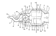
- FIG. 1 is a left side view of an electric motorcycle according to an embodiment of the present invention.
- FIG. 2 is a left side view of the main part of the electric motorcycle shown in FIG.
- FIG. 3 is a horizontal sectional view of a main part of the electric motorcycle shown in FIG. 2.
- FIG. 4 is a circuit diagram of an electric system including the electric component shown in FIG. 3.
- FIG. 3 is a cross-sectional view seen from the front of the space under the seat shown in FIG. It is a top view explaining the heat radiating hole of the battery case shown in FIG. It is a top view explaining the modification of the heat radiating hole of the battery case shown in FIG.
- FIG. 3 is a block diagram for explaining fan control of the electric motorcycle shown in FIG. 2.
- the present invention is a straddle-type electric motor in which a driver runs with power from an electric motor while driving over a seat. If it is a vehicle, it is applicable also to vehicles, such as ATV (All (Terrain Vehicle).
- ATV All (Terrain Vehicle).
- FIG. 1 is a left side view of an electric motorcycle 1 according to an embodiment of the present invention.
- the electric motorcycle 1 does not include an internal combustion engine, and travels by rotating the rear wheels 11 with power from the electric motor 22.
- the electric motorcycle 1 includes a front fork 2 provided in a substantially vertical direction with a predetermined caster angle, and a front wheel 3 as a driven wheel is rotatably supported at a lower portion of the front fork 2.
- a lower part of a steering shaft 4 (see FIG. 3) is connected to the upper part of the front fork 2, and a bar-type handle 5 is attached to the upper part of the steering shaft 4.
- An accelerator grip 5a is provided at a portion of the handle 5 that the driver grips with the right hand.
- the steering shaft 4 (see FIG. 3) is rotatably inserted into a head pipe 7 constituting the vehicle body frame 6, and the front wheel 3 is steered when the driver rotates the handle 5.
- the body frame 6 includes a head pipe 7 and a pair of left and right and upper and lower main frame portions 8 extending rearward while tilting slightly downward from the head pipe 7.
- the rear part of the main frame part 8 is connected to a pair of left and right pivot frame parts 9.
- the pivot frame portion 9 pivotally supports a front portion of a swing arm 10 extending substantially in the front-rear direction, and a rear wheel 11 as a drive wheel is rotatably supported on the rear portion of the swing arm 10.
- the main frame portion 8 and the pivot frame portion 9 are connected to a seat frame portion 12 that supports a seat 13 on which a driver or the like rides.
- An introduction duct 16 is provided in front of the battery case 15 and in the vicinity of the head pipe 7 for taking in the traveling wind from the front and guiding the traveling wind into the battery case 15. It is connected to the front upper part of the case 15.
- An exhaust duct 17 is provided at the rear of the battery case 15 and below the seat 13 for discharging the traveling wind flowing through the battery case 15 to the rear, and the front end of the exhaust duct 17 is the rear side of the battery case 15. Connected to the top.
- a cover 18 that forms a seat lower space 54 (see FIG. 2) is provided behind the exhaust duct 17 and below the seat 13.
- the vehicle body frame 6 includes a down frame portion 20 that is inclined downward from the main pipe portion 8 from the head pipe 7 and extends along the lower side of the battery case 15.
- An electric motor unit 21 is fixed to the rear end portion of the down frame portion 20, and the electric motor unit 21 is fixed to the main frame portion 8 and the pivot frame portion 9. That is, the main frame portion 8 and the pivot frame portion 9 are connected to the down frame portion 20 via the electric motor unit 21, and the electric motor unit 21 constitutes a part of the vehicle body frame 6.
- the electric motor unit 21 is disposed below the main frame portion 8 and the battery case 15 and in front of the pivot frame portion 9.
- the electric motor unit 21 includes an electric motor 22 that generates a driving force for driving and a transmission 23 that is integrally provided at a rear portion thereof.
- An inverter 25 is attached to the down frame portion 20 in front of the electric motor unit 21, and a controller 26 is attached to the rear portion of the battery case 15. Then, electric power from the battery 27 (see FIG. 2) is supplied to the electric motor 22 via the inverter 25, and rotational power is generated in the electric motor 22. The generated rotational power is shifted by the transmission 23 and transmitted to the rear wheel 11 via the chain 24.
- FIG. 2 is a left side view of the main part of the electric motorcycle 1 shown in FIG.
- the introduction duct 16, the battery case 15, and the exhaust duct 17 form a traveling wind passage 50 through which traveling wind generated when the electric motorcycle 1 travels flows from the front toward the rear.
- the introduction duct 16 has an internal passage 51 extending in the front-rear direction, and is curved and piped so that an intermediate portion thereof bypasses the head pipe 7.
- the introduction duct may have a structure in which the head pipe 7 penetrates the introduction duct in an up-and-down direction.
- a traveling wind inlet 16 a that opens forward is provided at the front end of the introduction duct 16, and the traveling wind inlet 16 a is located in front of the head pipe 7.
- a traveling wind communication port 16 b at the rear end of the introduction duct 16 communicates with a traveling wind inlet 15 a on the upper front side of the battery case 15.
- the introduction duct 16 has a sub chamber portion 16c that bulges downward at an intermediate portion in the front-rear direction.
- the area of the cross section of the flow path where the sub chamber portion 16c exists is larger than the areas of the traveling wind introduction port 16a and the traveling wind communication port 16b, and is twice or more larger in this embodiment.
- the sub chamber portion 16c that partially expands the cross-sectional area of the flow path temporarily reduces the flow rate of air in the internal passage 51, and it is easy to trap rain and dust from the outside in the sub chamber portion 16c.
- the sub chamber portion 16c is provided with a drain hole (not shown).
- a traveling wind inlet 15 a for allowing traveling wind to flow into the battery case 15 from the front is formed.
- a traveling wind outlet 15 b is formed on the upper side of the rear wall portion of the battery case 15 to allow the traveling wind flowing into the battery case 15 to flow backward.
- the traveling wind inlet 15a is positioned in front of the front-rear direction center of the main frame 8 in a side view, and the traveling wind outlet 15b is positioned rearward of the front-rear center of the main frame 8 in a side view.
- the traveling wind inlet 15 a is disposed at a position lower than the upper end of the head pipe 7 and higher than the lower end of the head pipe 7.
- the traveling wind outlet 15 b is disposed at a position higher than the center of the height of the portion of the pair of upper and lower main frame portions 8 at the same position in the front-rear direction as the traveling wind outlet 15 b and lower than the seat 13.
- a filter 36 made of non-woven fabric or the like is disposed at the traveling wind inlet 15a of the battery case 15 so as to capture foreign matter, rainwater, etc. contained in the traveling wind flowing into the internal space 52 of the battery case 15 from the introduction duct 16. I have to.
- a plurality of batteries 27 are arranged side by side vertically and horizontally.
- the battery 27 is positioned in the battery case 15 by a bracket (not shown) or the like.
- an electrical component installation plate 29 is provided as an electrical component installation unit 29 that protrudes rearward from the vicinity of the lower part of the traveling wind inlet 15 a on the front wall of the battery case 15.
- An electrical component 30 that is electrically connected to the battery 27 and generates heat during operation is installed in the electrical component installation unit 29.
- a traveling wind inlet and a traveling wind outlet communicating with the introduction duct 16 or the exhaust duct 17 are not provided. That is, in the internal space 52 of the battery case 15, the lower region is a convection zone and the upper region is a traveling wind passage zone.
- a fan 28 is accommodated and disposed below the battery 27 in the internal space 52 of the battery case 15. The high-temperature air naturally moves upward in the internal space of the battery case 15, but when the fan 28 is driven, the heat existing below the battery 27 is diffused and the heat is more preferably released upward. It becomes possible.
- the fan 28 may be provided in the vicinity (28X in FIG. 2) of the heat radiating hole 31b of the opening / closing lid 32 on the upper side of the battery case 15 or in the exhaust duct 17 (28Y in FIG. 2). Good. In these cases, the fans 28X and 28Y that have a function of blowing air from the battery case 15 to the outside are used.
- the upper wall portion of the battery case 15 forms a traveling-air dedicated passage 52f with a gap between the battery case 15 and the battery 27 accommodated in the internal space 52.
- a recess 31 that opens upward is formed on the upper wall portion of the battery case 15, and an opening / closing lid 32 is provided so as to cover the recess 31.
- the opening / closing lid 32 has a front end portion 32a attached to the battery case 15 so as to be rotatable.
- a battery charging connector 34 and an AC / DC converter 33 are accommodated in the recess 31, and the AC / DC converter 33 is connected to the battery 27 via an electric wire.
- the battery charging connector may be a quick charging connector.
- the battery charging connector 34 is exposed to the outside by opening the opening / closing lid 32.
- An open / close detection switch 35 that detects the open / close state of the open / close lid 32 is provided on the bottom wall 31 a of the recess 31.
- the bottom wall 31a of the recess 31 is formed with a heat radiation hole 31b through which air in the internal space 52 of the battery case 15 can be discharged to the outside.
- the bottom wall 31a of the recess 31 and the open / close lid 32 in the closed state are provided so as to incline downward as going backward. Therefore, when the rear end portion of the opening / closing lid 32 is lifted and opened, the opening / closing lid 32 is positioned above the heat radiation hole 31b.
- a traveling wind communication port 17 a at the front end of the exhaust duct 17 is connected to the traveling wind outlet 15 b of the battery case 15.
- the exhaust duct 17 has an internal passage 53 extending in the front-rear direction.
- the exhaust duct 17 is inclined slightly upward so that the rear portion thereof extends along the seat 13.
- the rear end of the exhaust duct 17 is provided with a traveling wind discharge port 17 b that opens rearward.
- the traveling wind discharge port 17 b communicates with a seat lower space 54 formed below the seat 13. Yes. This prevents rainwater or the like from entering the exhaust duct 17 from the traveling wind outlet 17b.
- the traveling wind passage 50 is formed by the internal passage 51 of the introduction duct 16, the upper region of the internal space 52 of the battery case 15, and the internal space 53 of the exhaust duct 17.
- the traveling wind passage 50 is electrically driven in a side view.
- the two-wheeled vehicle 1 is formed to extend in the front-rear direction above the center of the height.
- the traveling wind flowing in from the traveling wind introduction port 16a flows in the order of the introduction duct 16, the battery case 15, and the exhaust duct 17 and is discharged to the outside from the space under the seat 54.
- FIG. 3 is a horizontal sectional view of an essential part of the electric motorcycle 1 shown in FIG.
- FIG. 4 is a circuit diagram of an electrical system including the electrical component 30 shown in FIG.
- the introduction duct 16 has a running wind introduction port 16 a located in front of the head pipe 7, and a running wind communication port 16 b located in the rear of the head pipe 7. Curved to bypass the side.
- An electrical component installation portion 29 is provided in the front region 52a of the battery case 15, and the batteries 27 are arranged side by side in the battery housing region 52b on the rear side of the front region 52a.
- the left and right batteries 27 form a traveling-air dedicated passage 52c with a gap serving as a central passage between them.
- the left and right batteries 27 are also provided with traveling air dedicated passages 52d and 52e with a space between the left and right side walls of the battery case 15.
- the electrical component installation unit 29 is mounted with a terminal block 40 and an electrical component 30 connected to the battery 27 via a high-voltage electric wire connected to the terminal block 40.
- the electrical component 30 includes relays 37 and 38 provided in a circuit connecting the battery 27 and the inverter 25, and a current sensor 39 that detects a current value flowing on the circuit (see FIG. 4).
- the relays 37 and 38 and the current sensor 39 generate heat and become high temperature during traveling.
- the battery case 15 is formed such that, in plan view, the size L1 in the vehicle width direction in the region 52a in which the electrical component 30 is disposed is smaller than the size L2 in the vehicle width direction in the region 52b in which the battery 27 is disposed. Thereby, in the battery case 15, the flow path area in the area
- FIG. 5 is a cross-sectional view seen from the front of the under-seat space 54 shown in FIG.
- the under-seat space 54 is formed by the sheet 13 and the cover 18 disposed below the sheet 13.
- the sheet 13 includes an upper wall portion 13a and side wall portions 13b and 13c protruding downward from the left and right ends of the upper wall portion 13a, and has a reverse concave shape in cross section when viewed from the front.
- the cover 18 includes a lower wall portion 18a and side wall portions 18b and 18c protruding upward from the left and right ends of the lower wall portion 18a, and has a concave cross-sectional shape when viewed from the front.
- the size W2 of the cover 18 in the vehicle width direction is smaller than the size W1 of the seat 13 in the vehicle width direction.
- the side wall portions 13b and 13c of the sheet 13 and the side wall portions 13b and 13c of the cover 18 are overlapped with each other so as to form a gap 55 therebetween. That is, the air in the seat lower space 54 is discharged from the left and right gaps 55 to the outside in the vehicle width direction.
- FIG. 6A is a plan view for explaining the heat radiation hole 31b of the battery case 15 shown in FIG.
- FIG. 6B is a plan view for explaining a modification of the heat radiating hole 131b of the battery case 15 shown in FIG.
- the heat sink hole 31b which consists of several slits is formed in the bottom wall part 31a of the recessed part 31 (refer FIG. 2) of the battery case 15.
- the heat generated from the battery 27 when charging is performed by opening the opening / closing lid 32 (see FIG. 2) is released upward through the heat radiation hole 31b, so that a heat radiation effect is exhibited.
- a heat dissipation hole 131b covered with a mesh 41 may be provided in the bottom wall portion 131a of the recess provided in the upper wall portion of the battery case 15. Good.
- FIG. 7 is a block diagram for explaining fan control of the electric motorcycle 1 shown in FIG.
- an open / close detection switch 35 and a current sensor 39 are connected to the input side of the controller 26, and a fan 28 is connected to the output side of the controller 26.
- the controller 26 includes a charge determination unit 43, a battery state determination unit 44, and a fan control unit 45.
- the charge determination unit 43 determines whether or not the battery 27 is being charged based on a signal from the open / close detection switch 35.
- the charging determination unit 43 determines that the battery 27 is in a charged state, and the opening / closing lid 32 is opened from the opening / closing detection switch 35.
- a signal indicating that the battery is closed is received, it is determined that the battery 27 is not charged.
- Battery state determination unit 44 determines the heat generation state of battery 27 based on a signal from current sensor 39. Specifically, the battery state determination unit 44 determines that the battery is in a high heat generation state when the current value detected by the current sensor 39 is equal to or greater than a predetermined threshold, and the current value detected by the current sensor 39. Is less than a predetermined threshold value, it is determined that the battery is in a low heat generation state.
- the fan control unit 45 controls the fan 28 to be driven when the charge determination unit 43 determines that the battery is being charged and when the battery state determination unit 44 determines that the battery is in a high heat generation state. In other cases, the fan 28 is controlled to be stopped.
- the traveling wind flows into the battery case 15 from the front, cools the battery 27, and the traveling wind that exchanges heat with the battery 27 flows into the battery case 15. It flows backward.
- the traveling wind inlet 15a is formed on the upper front side of the battery case 15 and the traveling wind outlet 15b is formed on the rear upper side of the battery case 15, the traveling wind is above the inner space 52 of the battery case 15. It flows through the area from the front to the rear. That is, the traveling wind flows smoothly in the battery case 15 and the air whose temperature has increased and is collected in the upper region in the battery case 15 is efficiently discharged. Therefore, it is possible to efficiently cool the battery for driving with a simple configuration while suppressing the driving wind resistance and improving the high-speed driving performance.
- traveling wind passages 52c to 52f in which the battery 27 is not disposed.
- the traveling wind flowing into the battery case 15 from the traveling wind inlet 15a passes through the traveling wind passages 52c to 52f and flows out from the traveling wind outlet 15b, so that the flow of the traveling wind is very smooth.
- the introduction duct 16 having the traveling wind inlet 16a disposed in front of the head pipe 7 is provided, the traveling wind from the front is smoothly guided into the battery case 15 disposed behind the head pipe 7. It is burned.
- the traveling wind that flows backward from the battery case 15 flows through the exhaust duct 17 in the front-rear direction as it is, the traveling wind is smoothly discharged. Therefore, it is possible to sufficiently suppress the resistance caused by the traveling wind flowing through the traveling wind passage 50.
- traveling wind outlet 17b of the traveling wind passage 50 is disposed in the under-seat space 54, it is possible to easily prevent rainwater or the like from entering the traveling wind passage 50 from the traveling wind outlet 17b. .
- traveling wind discharged from the traveling wind passage 50 to the seat lower space 54 passes outside through the gap 55 between the seat 13 and the cover 18 to both sides in the vehicle width direction, the traveling wind flows. Can be further smoothed.
- the electrical component 30 that generates heat during travel is provided in the electrical component installation portion 29 on the upstream side of the battery 27, the electrical component 30 can be effectively cooled by the travel wind before the battery 27 is cooled.
- the electric component installation portion 29 is arranged so as to partition the internal space 52 of the battery case 15 in the vertical direction, the size in the height direction of the region 52a where the electric component 30 is arranged is reduced, and the battery case 15 The size L1 in the vehicle width direction of the region 52a where the electrical component 30 is arranged is small.
- the flow passage area of the region 52a where the electric component 30 is arranged in the battery case 15 is reduced, and the electric component 30 that generates heat during the traveling of the electric motorcycle 1 can be effectively cooled with the traveling airflow at a high flow rate. it can. Furthermore, since the portion immediately after the head pipe 7 in the battery case 15 becomes smaller, the handling of the handle 5 can be facilitated.
- the heat generated from the battery 27 can be radiated from the heat radiation hole 31b exposed to the outside by opening the opening / closing lid 32.
- the fan 28 operates when the electric motorcycle 1 stops traveling and the battery 27 is in a charged state, even if the battery 27 generates heat due to charging in the absence of traveling wind, heat is suitably radiated from the heat radiation hole 31b. be able to.
- the introduction duct 16 and / or the exhaust duct 17 are connected to the battery case 15.
- the traveling wind inlet 15a of the battery case 15 may be used as an inlet for introducing traveling wind from the outside.
- the traveling wind outlet 15b of the case 15 may be an outlet for discharging the traveling wind to the outside.
- the separate introduction duct 16 and / or the exhaust duct 17 are connected to the battery case 15, but the introduction duct 16 and / or the exhaust duct 17 are formed integrally with the battery case 15. Also good.
- the straddle-type electric vehicle according to the present invention can efficiently cool the battery for driving with a simple configuration while suppressing the driving wind resistance and improving the high-speed driving performance.
- the present invention is beneficial when applied widely to straddle-type electric vehicles such as electric motorcycles that have such excellent effects.
Landscapes
- Engineering & Computer Science (AREA)
- Mechanical Engineering (AREA)
- Chemical & Material Sciences (AREA)
- Combustion & Propulsion (AREA)
- Transportation (AREA)
- Automatic Cycles, And Cycles In General (AREA)
- Arrangement Or Mounting Of Propulsion Units For Vehicles (AREA)
- Electric Propulsion And Braking For Vehicles (AREA)
- Secondary Cells (AREA)
- Battery Mounting, Suspending (AREA)
Abstract
Priority Applications (5)
| Application Number | Priority Date | Filing Date | Title |
|---|---|---|---|
| JP2012549484A JP5584315B2 (ja) | 2010-12-24 | 2010-12-24 | 鞍乗型電動車両 |
| EP10860985.0A EP2657114B1 (fr) | 2010-12-24 | 2010-12-24 | Véhicule électrique à selle |
| US13/997,176 US8973697B2 (en) | 2010-12-24 | 2010-12-24 | Saddle-type electric vehicle |
| CN201080070669.8A CN103237719B (zh) | 2010-12-24 | 2010-12-24 | 跨乘式电动车辆 |
| PCT/JP2010/007479 WO2012085976A1 (fr) | 2010-12-24 | 2010-12-24 | Véhicule électrique à selle |
Applications Claiming Priority (1)
| Application Number | Priority Date | Filing Date | Title |
|---|---|---|---|
| PCT/JP2010/007479 WO2012085976A1 (fr) | 2010-12-24 | 2010-12-24 | Véhicule électrique à selle |
Publications (1)
| Publication Number | Publication Date |
|---|---|
| WO2012085976A1 true WO2012085976A1 (fr) | 2012-06-28 |
Family
ID=46313280
Family Applications (1)
| Application Number | Title | Priority Date | Filing Date |
|---|---|---|---|
| PCT/JP2010/007479 WO2012085976A1 (fr) | 2010-12-24 | 2010-12-24 | Véhicule électrique à selle |
Country Status (5)
| Country | Link |
|---|---|
| US (1) | US8973697B2 (fr) |
| EP (1) | EP2657114B1 (fr) |
| JP (1) | JP5584315B2 (fr) |
| CN (1) | CN103237719B (fr) |
| WO (1) | WO2012085976A1 (fr) |
Cited By (7)
| Publication number | Priority date | Publication date | Assignee | Title |
|---|---|---|---|---|
| CN104884344A (zh) * | 2012-12-25 | 2015-09-02 | 川崎重工业株式会社 | 跨乘式交通工具 |
| WO2016125728A1 (fr) * | 2015-02-02 | 2016-08-11 | シャープ株式会社 | Dispositif de déplacement autonome |
| JP2018052353A (ja) * | 2016-09-29 | 2018-04-05 | 本田技研工業株式会社 | 鞍乗り型電動車両の燃料電池スタック固定構造 |
| US10466699B2 (en) | 2015-02-02 | 2019-11-05 | Sharp Kabushiki Kaisha | Autonomous travel device |
| JP2020097314A (ja) * | 2018-12-18 | 2020-06-25 | スズキ株式会社 | 鞍乗型車両 |
| WO2023127136A1 (fr) * | 2021-12-28 | 2023-07-06 | 本田技研工業株式会社 | Véhicule à selle |
| EP4155180A4 (fr) * | 2020-11-10 | 2024-01-17 | Zhejiang CFMOTO Power Co., Ltd. | Motocyclette électrique |
Families Citing this family (31)
| Publication number | Priority date | Publication date | Assignee | Title |
|---|---|---|---|---|
| WO2012063292A1 (fr) * | 2010-11-12 | 2012-05-18 | 川崎重工業株式会社 | Structure de montage pour des dispositifs d'accumulateurs dans un véhicule électrique |
| JP5923115B2 (ja) * | 2011-12-28 | 2016-05-24 | 川崎重工業株式会社 | 鞍乗型電動車両 |
| WO2014102846A1 (fr) * | 2012-12-25 | 2014-07-03 | 川崎重工業株式会社 | Véhicule électrique |
| US20140305729A1 (en) * | 2013-04-12 | 2014-10-16 | CRP SERVICE S.r.I. | Electric motorcycle |
| JP2016002896A (ja) * | 2014-06-17 | 2016-01-12 | ヤマハ発動機株式会社 | 鞍乗型電動車両 |
| JP6510243B2 (ja) * | 2015-01-16 | 2019-05-08 | 株式会社Subaru | 車載用バッテリー |
| US10023264B2 (en) * | 2015-04-02 | 2018-07-17 | GM Global Technology Operations LLC | Cooling method for E-bike power and energy systems |
| JP6224668B2 (ja) * | 2015-09-24 | 2017-11-01 | 本田技研工業株式会社 | 鞍乗型車両 |
| JP2017081330A (ja) * | 2015-10-27 | 2017-05-18 | スズキ株式会社 | 電動二輪車用の外装構造 |
| JP6561770B2 (ja) * | 2015-10-27 | 2019-08-21 | スズキ株式会社 | 電動車両の構造 |
| US20170282749A1 (en) * | 2016-03-31 | 2017-10-05 | Honda Motor Co., Ltd. | Saddle-ride type vehicle |
| US10632857B2 (en) | 2016-08-17 | 2020-04-28 | Shape Corp. | Battery support and protection structure for a vehicle |
| EP3566253B1 (fr) | 2017-01-04 | 2022-12-28 | Shape Corp. | Structure de support de batterie pour un véhicule |
| US10483510B2 (en) | 2017-05-16 | 2019-11-19 | Shape Corp. | Polarized battery tray for a vehicle |
| US10886513B2 (en) | 2017-05-16 | 2021-01-05 | Shape Corp. | Vehicle battery tray having tub-based integration |
| WO2018213383A1 (fr) | 2017-05-16 | 2018-11-22 | Shape Corp. | Support de batterie de véhicule à 'éléments de retenue et de support de batterie intégrés |
| CN107161253B (zh) * | 2017-06-09 | 2019-08-16 | 诸大淼 | 一种快速锁止式共享单车 |
| CN111108015A (zh) | 2017-09-13 | 2020-05-05 | 形状集团 | 具有管状外围壁的车辆电池托盘 |
| JP6825122B2 (ja) * | 2017-09-29 | 2021-02-03 | 本田技研工業株式会社 | 鞍乗り型電動車両 |
| DE112018005556T5 (de) | 2017-10-04 | 2020-06-25 | Shape Corp. | Batterieträger-bodenbaugruppe für elektrofahrzeuge |
| WO2019169080A1 (fr) | 2018-03-01 | 2019-09-06 | Shape Corp. | Système de refroidissement intégré à un bac de batterie de véhicule |
| US11688910B2 (en) | 2018-03-15 | 2023-06-27 | Shape Corp. | Vehicle battery tray having tub-based component |
| JP6673962B2 (ja) * | 2018-03-28 | 2020-04-01 | 本田技研工業株式会社 | 電装品の配置構造 |
| WO2019186947A1 (fr) * | 2018-03-29 | 2019-10-03 | 本田技研工業株式会社 | Véhicule électrique du type à enfourcher à selle |
| WO2019186952A1 (fr) * | 2018-03-29 | 2019-10-03 | 本田技研工業株式会社 | Véhicule électrique du type à enfourcher |
| DE112018007389B4 (de) * | 2018-03-29 | 2024-10-17 | Honda Motor Co., Ltd. | Elektrisches fahrzeug vom grätschsitztyp |
| JP6708712B2 (ja) * | 2018-08-20 | 2020-06-10 | 本田技研工業株式会社 | 鞍乗型車両 |
| JP7354800B2 (ja) * | 2019-11-29 | 2023-10-03 | スズキ株式会社 | 鞍乗型電動車両 |
| JP7347166B2 (ja) * | 2019-11-29 | 2023-09-20 | スズキ株式会社 | 鞍乗型車両 |
| JP7437251B2 (ja) | 2020-07-07 | 2024-02-22 | カワサキモータース株式会社 | 鞍乗車両 |
| JP2023015905A (ja) * | 2021-07-20 | 2023-02-01 | ヤマハ発動機株式会社 | 電動車両 |
Citations (9)
| Publication number | Priority date | Publication date | Assignee | Title |
|---|---|---|---|---|
| JPH10297570A (ja) * | 1997-05-01 | 1998-11-10 | Yamaha Motor Co Ltd | ハイブリッド式二輪車 |
| JP2001106162A (ja) * | 1999-10-14 | 2001-04-17 | Yamaha Motor Co Ltd | シリーズハイブリッド式電動二輪車 |
| JP2001351653A (ja) * | 2000-06-02 | 2001-12-21 | Yamaha Motor Co Ltd | 燃料電池システム |
| JP2002037167A (ja) * | 2000-07-24 | 2002-02-06 | Yamaha Motor Co Ltd | 自動二輪車 |
| JP2002362470A (ja) * | 2001-06-13 | 2002-12-18 | Yamaha Motor Co Ltd | 電動車両 |
| JP2003019992A (ja) * | 2001-07-09 | 2003-01-21 | Yamaha Motor Co Ltd | スクータ型自動二輪車の冷却装置 |
| JP2008080986A (ja) | 2006-09-28 | 2008-04-10 | Honda Motor Co Ltd | バッテリ搭載機構 |
| JP2010195272A (ja) * | 2009-02-26 | 2010-09-09 | Suzuki Motor Corp | 自動二輪車 |
| JP2010228660A (ja) * | 2009-03-27 | 2010-10-14 | Honda Motor Co Ltd | 電動二輪車のバッテリ装置 |
Family Cites Families (13)
| Publication number | Priority date | Publication date | Assignee | Title |
|---|---|---|---|---|
| JP2900174B2 (ja) | 1990-05-18 | 1999-06-02 | 本田技研工業株式会社 | 電動式スクータ型自動二,三輪車 |
| JP2545948Y2 (ja) * | 1990-12-27 | 1997-08-27 | 本田技研工業株式会社 | 充電式電動二輪車 |
| JP3179508B2 (ja) * | 1991-02-27 | 2001-06-25 | 本田技研工業株式会社 | 電動車両用充電装置 |
| IT1260903B (it) * | 1992-03-04 | 1996-04-29 | Honda Motor Co Ltd | Motoveicolo a trazione elettrica. |
| JPH06278667A (ja) * | 1993-01-26 | 1994-10-04 | Honda Motor Co Ltd | 電動車両 |
| JP4010834B2 (ja) * | 2002-03-19 | 2007-11-21 | 本田技研工業株式会社 | スロットルセンサの取付構造 |
| JP3708067B2 (ja) * | 2002-08-09 | 2005-10-19 | 川崎重工業株式会社 | 弾塑性体の亀裂進展予測方法および変形予測方法 |
| JPWO2004069638A1 (ja) * | 2003-02-07 | 2006-05-25 | ヤマハ発動機株式会社 | 電動二輪車 |
| JP2007062643A (ja) * | 2005-09-01 | 2007-03-15 | Yamaha Motor Co Ltd | 自動二輪車の車体冷却構造および自動二輪車 |
| JP2007118628A (ja) * | 2005-10-24 | 2007-05-17 | Yamaha Motor Co Ltd | 鞍乗型車両 |
| JP2009225526A (ja) * | 2008-03-14 | 2009-10-01 | Gs Yuasa Corporation | 冷却装置 |
| JP4908490B2 (ja) * | 2008-12-26 | 2012-04-04 | 本田技研工業株式会社 | 鞍乗型電動車両のバッテリ収納箱構造 |
| US8455128B2 (en) * | 2010-01-19 | 2013-06-04 | U.S. Alternative Energy, LLC | Battery system for electric motorcycle |
-
2010
- 2010-12-24 CN CN201080070669.8A patent/CN103237719B/zh active Active
- 2010-12-24 US US13/997,176 patent/US8973697B2/en active Active
- 2010-12-24 EP EP10860985.0A patent/EP2657114B1/fr active Active
- 2010-12-24 JP JP2012549484A patent/JP5584315B2/ja active Active
- 2010-12-24 WO PCT/JP2010/007479 patent/WO2012085976A1/fr active Application Filing
Patent Citations (9)
| Publication number | Priority date | Publication date | Assignee | Title |
|---|---|---|---|---|
| JPH10297570A (ja) * | 1997-05-01 | 1998-11-10 | Yamaha Motor Co Ltd | ハイブリッド式二輪車 |
| JP2001106162A (ja) * | 1999-10-14 | 2001-04-17 | Yamaha Motor Co Ltd | シリーズハイブリッド式電動二輪車 |
| JP2001351653A (ja) * | 2000-06-02 | 2001-12-21 | Yamaha Motor Co Ltd | 燃料電池システム |
| JP2002037167A (ja) * | 2000-07-24 | 2002-02-06 | Yamaha Motor Co Ltd | 自動二輪車 |
| JP2002362470A (ja) * | 2001-06-13 | 2002-12-18 | Yamaha Motor Co Ltd | 電動車両 |
| JP2003019992A (ja) * | 2001-07-09 | 2003-01-21 | Yamaha Motor Co Ltd | スクータ型自動二輪車の冷却装置 |
| JP2008080986A (ja) | 2006-09-28 | 2008-04-10 | Honda Motor Co Ltd | バッテリ搭載機構 |
| JP2010195272A (ja) * | 2009-02-26 | 2010-09-09 | Suzuki Motor Corp | 自動二輪車 |
| JP2010228660A (ja) * | 2009-03-27 | 2010-10-14 | Honda Motor Co Ltd | 電動二輪車のバッテリ装置 |
Non-Patent Citations (1)
| Title |
|---|
| See also references of EP2657114A4 * |
Cited By (10)
| Publication number | Priority date | Publication date | Assignee | Title |
|---|---|---|---|---|
| CN104884344A (zh) * | 2012-12-25 | 2015-09-02 | 川崎重工业株式会社 | 跨乘式交通工具 |
| US9896144B2 (en) | 2012-12-25 | 2018-02-20 | Kawasaki Jukogyo Kabushiki Kaisha | Straddle-type vehicle |
| WO2016125728A1 (fr) * | 2015-02-02 | 2016-08-11 | シャープ株式会社 | Dispositif de déplacement autonome |
| US10466699B2 (en) | 2015-02-02 | 2019-11-05 | Sharp Kabushiki Kaisha | Autonomous travel device |
| JP2018052353A (ja) * | 2016-09-29 | 2018-04-05 | 本田技研工業株式会社 | 鞍乗り型電動車両の燃料電池スタック固定構造 |
| US10479434B2 (en) | 2016-09-29 | 2019-11-19 | Honda Motor Co., Ltd. | Saddle-riding-type electric vehicle fuel cell stack fixation structure |
| JP2020097314A (ja) * | 2018-12-18 | 2020-06-25 | スズキ株式会社 | 鞍乗型車両 |
| JP7131360B2 (ja) | 2018-12-18 | 2022-09-06 | スズキ株式会社 | 鞍乗型車両 |
| EP4155180A4 (fr) * | 2020-11-10 | 2024-01-17 | Zhejiang CFMOTO Power Co., Ltd. | Motocyclette électrique |
| WO2023127136A1 (fr) * | 2021-12-28 | 2023-07-06 | 本田技研工業株式会社 | Véhicule à selle |
Also Published As
| Publication number | Publication date |
|---|---|
| CN103237719B (zh) | 2016-01-06 |
| EP2657114B1 (fr) | 2016-05-11 |
| JPWO2012085976A1 (ja) | 2014-05-22 |
| CN103237719A (zh) | 2013-08-07 |
| US8973697B2 (en) | 2015-03-10 |
| EP2657114A1 (fr) | 2013-10-30 |
| JP5584315B2 (ja) | 2014-09-03 |
| US20130319782A1 (en) | 2013-12-05 |
| EP2657114A4 (fr) | 2014-05-14 |
Similar Documents
| Publication | Publication Date | Title |
|---|---|---|
| JP5584315B2 (ja) | 鞍乗型電動車両 | |
| JP5664788B2 (ja) | 車両の冷却装置 | |
| JP5292508B2 (ja) | 鞍乗り型電動車両の車両接近告知装置 | |
| US9027694B2 (en) | Saddle-type electric vehicle | |
| US9296444B2 (en) | Straddle electric vehicle | |
| WO2012066602A1 (fr) | Véhicule à selle | |
| US9643514B2 (en) | Straddle electric vehicle | |
| KR100663792B1 (ko) | 전동 차량의 냉각 구조 | |
| CN111836756B (zh) | 跨骑型电动车辆 | |
| CN111886179B (zh) | 跨骑型电动车辆 | |
| JP2013071548A (ja) | 電動車両 | |
| US9758215B2 (en) | Fuel cell two-wheeled vehicle | |
| JP6147540B2 (ja) | 鞍乗り型車両 | |
| JP5693859B2 (ja) | 電動車両用のバッテリ冷却装置 | |
| JP2010232084A (ja) | バッテリ搭載構造 | |
| JP4881648B2 (ja) | 自動二輪車 | |
| US20220009341A1 (en) | Straddle vehicle | |
| JP2010241367A (ja) | 車両の空気抵抗低減構造 | |
| JP2012096616A (ja) | 電動車両のバッテリ温度調整構造 | |
| JPWO2019059257A1 (ja) | 鞍乗り型車両 | |
| JP2023142837A (ja) | 電動ユニット | |
| JP7566999B1 (ja) | 電動車両 | |
| JP2022095234A (ja) | エンジンの排気構造 | |
| JP2017013710A (ja) | エンジン房冷却構造 |
Legal Events
| Date | Code | Title | Description |
|---|---|---|---|
| 121 | Ep: the epo has been informed by wipo that ep was designated in this application |
Ref document number: 10860985 Country of ref document: EP Kind code of ref document: A1 |
|
| ENP | Entry into the national phase |
Ref document number: 2012549484 Country of ref document: JP Kind code of ref document: A |
|
| WWE | Wipo information: entry into national phase |
Ref document number: 13997176 Country of ref document: US |
|
| NENP | Non-entry into the national phase |
Ref country code: DE |
|
| WWE | Wipo information: entry into national phase |
Ref document number: 2010860985 Country of ref document: EP |