WO2012077754A1 - ディスクブレーキ - Google Patents
ディスクブレーキ Download PDFInfo
- Publication number
- WO2012077754A1 WO2012077754A1 PCT/JP2011/078434 JP2011078434W WO2012077754A1 WO 2012077754 A1 WO2012077754 A1 WO 2012077754A1 JP 2011078434 W JP2011078434 W JP 2011078434W WO 2012077754 A1 WO2012077754 A1 WO 2012077754A1
- Authority
- WO
- WIPO (PCT)
- Prior art keywords
- disk
- pin
- torque receiving
- pair
- friction pads
- Prior art date
- Legal status (The legal status is an assumption and is not a legal conclusion. Google has not performed a legal analysis and makes no representation as to the accuracy of the status listed.)
- Ceased
Links
Images


Classifications
-
- F—MECHANICAL ENGINEERING; LIGHTING; HEATING; WEAPONS; BLASTING
- F16—ENGINEERING ELEMENTS AND UNITS; GENERAL MEASURES FOR PRODUCING AND MAINTAINING EFFECTIVE FUNCTIONING OF MACHINES OR INSTALLATIONS; THERMAL INSULATION IN GENERAL
- F16D—COUPLINGS FOR TRANSMITTING ROTATION; CLUTCHES; BRAKES
- F16D55/00—Brakes with substantially-radial braking surfaces pressed together in axial direction, e.g. disc brakes
- F16D55/02—Brakes with substantially-radial braking surfaces pressed together in axial direction, e.g. disc brakes with axially-movable discs or pads pressed against axially-located rotating members
- F16D55/22—Brakes with substantially-radial braking surfaces pressed together in axial direction, e.g. disc brakes with axially-movable discs or pads pressed against axially-located rotating members by clamping an axially-located rotating disc between movable braking members, e.g. movable brake discs or brake pads
- F16D55/224—Brakes with substantially-radial braking surfaces pressed together in axial direction, e.g. disc brakes with axially-movable discs or pads pressed against axially-located rotating members by clamping an axially-located rotating disc between movable braking members, e.g. movable brake discs or brake pads with a common actuating member for the braking members
- F16D55/225—Brakes with substantially-radial braking surfaces pressed together in axial direction, e.g. disc brakes with axially-movable discs or pads pressed against axially-located rotating members by clamping an axially-located rotating disc between movable braking members, e.g. movable brake discs or brake pads with a common actuating member for the braking members the braking members being brake pads
- F16D55/226—Brakes with substantially-radial braking surfaces pressed together in axial direction, e.g. disc brakes with axially-movable discs or pads pressed against axially-located rotating members by clamping an axially-located rotating disc between movable braking members, e.g. movable brake discs or brake pads with a common actuating member for the braking members the braking members being brake pads in which the common actuating member is moved axially, e.g. floating caliper disc brakes
- F16D55/2265—Brakes with substantially-radial braking surfaces pressed together in axial direction, e.g. disc brakes with axially-movable discs or pads pressed against axially-located rotating members by clamping an axially-located rotating disc between movable braking members, e.g. movable brake discs or brake pads with a common actuating member for the braking members the braking members being brake pads in which the common actuating member is moved axially, e.g. floating caliper disc brakes the axial movement being guided by one or more pins engaging bores in the brake support or the brake housing
- F16D55/227—Brakes with substantially-radial braking surfaces pressed together in axial direction, e.g. disc brakes with axially-movable discs or pads pressed against axially-located rotating members by clamping an axially-located rotating disc between movable braking members, e.g. movable brake discs or brake pads with a common actuating member for the braking members the braking members being brake pads in which the common actuating member is moved axially, e.g. floating caliper disc brakes the axial movement being guided by one or more pins engaging bores in the brake support or the brake housing by two or more pins
-
- F—MECHANICAL ENGINEERING; LIGHTING; HEATING; WEAPONS; BLASTING
- F16—ENGINEERING ELEMENTS AND UNITS; GENERAL MEASURES FOR PRODUCING AND MAINTAINING EFFECTIVE FUNCTIONING OF MACHINES OR INSTALLATIONS; THERMAL INSULATION IN GENERAL
- F16D—COUPLINGS FOR TRANSMITTING ROTATION; CLUTCHES; BRAKES
- F16D65/00—Parts or details
- F16D65/02—Braking members; Mounting thereof
- F16D65/04—Bands, shoes or pads; Pivots or supporting members therefor
- F16D65/092—Bands, shoes or pads; Pivots or supporting members therefor for axially-engaging brakes, e.g. disc brakes
-
- F—MECHANICAL ENGINEERING; LIGHTING; HEATING; WEAPONS; BLASTING
- F16—ENGINEERING ELEMENTS AND UNITS; GENERAL MEASURES FOR PRODUCING AND MAINTAINING EFFECTIVE FUNCTIONING OF MACHINES OR INSTALLATIONS; THERMAL INSULATION IN GENERAL
- F16D—COUPLINGS FOR TRANSMITTING ROTATION; CLUTCHES; BRAKES
- F16D55/00—Brakes with substantially-radial braking surfaces pressed together in axial direction, e.g. disc brakes
- F16D2055/0004—Parts or details of disc brakes
- F16D2055/0008—Brake supports
-
- F—MECHANICAL ENGINEERING; LIGHTING; HEATING; WEAPONS; BLASTING
- F16—ENGINEERING ELEMENTS AND UNITS; GENERAL MEASURES FOR PRODUCING AND MAINTAINING EFFECTIVE FUNCTIONING OF MACHINES OR INSTALLATIONS; THERMAL INSULATION IN GENERAL
- F16D—COUPLINGS FOR TRANSMITTING ROTATION; CLUTCHES; BRAKES
- F16D55/00—Brakes with substantially-radial braking surfaces pressed together in axial direction, e.g. disc brakes
- F16D2055/0075—Constructional features of axially engaged brakes
- F16D2055/0091—Plural actuators arranged side by side on the same side of the rotor
-
- F—MECHANICAL ENGINEERING; LIGHTING; HEATING; WEAPONS; BLASTING
- F16—ENGINEERING ELEMENTS AND UNITS; GENERAL MEASURES FOR PRODUCING AND MAINTAINING EFFECTIVE FUNCTIONING OF MACHINES OR INSTALLATIONS; THERMAL INSULATION IN GENERAL
- F16D—COUPLINGS FOR TRANSMITTING ROTATION; CLUTCHES; BRAKES
- F16D2121/00—Type of actuator operation force
- F16D2121/02—Fluid pressure
- F16D2121/04—Fluid pressure acting on a piston-type actuator, e.g. for liquid pressure
Definitions
- the present invention relates to a disc brake for braking a vehicle.
- This application claims priority based on Japanese Patent Application No. 2010-276191 filed in Japan on December 10, 2010, the contents of which are incorporated herein by reference.
- a disc brake for braking a vehicle is configured to bring a friction pad into contact with a disc rotating with a wheel by a caliper and perform braking by the frictional resistance.
- a structure is known in which a carrier that supports a caliper receives braking torque generated in a friction pad during braking (see, for example, Patent Document 1).
- the present invention aims to provide a disc brake capable of improving productivity.
- the disc brake is supported by the carrier so as to be fixed to the non-rotating portion of the vehicle, and is slidably supported by the carrier.
- a pair of friction pads disposed on both sides of the disk, and a caliper that has a piston that presses one of the pair of friction pads and is slidably supported by the carrier.
- the carrier is provided with one torque receiving pin that is disposed on the disk entry side when the vehicle moves forward, extends across the disk in the axial direction of the disk, and slides with a pair of friction pads.
- the pair of friction pads are formed with insertion holes through which the torque receiving pins are inserted on the respective disk insertion sides.
- the one torque receiving pin is configured to receive a braking torque in the disk rotation direction generated in the pair of friction pads during braking when the vehicle moves forward.
- the engagement portion is formed on the disk delivery side of each of the pair of friction pads when the vehicle moves forward, and the engagement hole through which the pad pin supported by the caliper is inserted. It is.
- the engagement hole and the pad pin are provided with a gap in the disc rotation direction so as not to receive a braking torque when the vehicle moves forward.
- the engaging portion is provided on each of the pair of friction pads at a distance that is approximately twice the distance between the center of the torque receiving pin and the circumferential center of the friction pad.
- the engagement hole is formed at a position away from the center of the torque receiving pin and through which the pad pin supported by the caliper is inserted.
- the center in the disk circumferential direction coincides with the center of the line segment connecting the insertion hole and the engagement hole in the position in the disk circumferential direction. ing.
- a portion where the pair of friction pads slide is circular.
- the torque receiving pin has a portion that extends from the fixing portion to the carrier in a direction away from the disk in a disk axial direction and slidably supports the caliper. .
- the productivity of the disc brake can be improved.
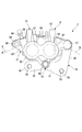
- 1 is a plan view showing a disc brake according to a first embodiment of the present invention.
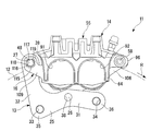
- 1 is a front view showing a disc brake according to a first embodiment of the present invention. It is a sectional side view showing the disc brake concerning a 1st embodiment of the present invention. It is a rear view which shows the disc brake which concerns on 1st Embodiment of this invention. It is a top view which shows the carrier of a disc brake which concerns on 1st Embodiment of this invention, a pair of friction pad, and a disc. It is a front view showing a carrier of a disc brake concerning a 1st embodiment of the present invention, a pair of friction pads, and a disc.
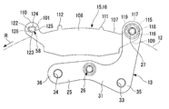
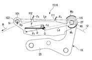
- FIG. 1 is a front view showing a carrier, a pad pin, a pair of friction pads and a disc of a disc brake according to a first embodiment of the present invention, dimensions of each part, directions of forces and moments, and the like.
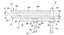
- FIG. It is a front view which shows an example of the attachment state to the vehicle of the disc brake which concerns on 1st Embodiment of this invention. It is a front view which shows another example of the attachment state to the vehicle of the disc brake which concerns on 1st Embodiment of this invention. It is a top view which shows the disc brake which concerns on 2nd Embodiment of this invention. It is a front sectional view showing a disc brake concerning a 2nd embodiment of the present invention.
- the disc brake according to the first embodiment of the present invention is a disc brake for vehicles, specifically for motorcycles.
- the disc brake 11 includes a carrier 13 fixed to the vehicle body, a caliper 14 straddling the disc 12 fixed to the wheel, a pair of friction pads 15 and 16, and a pad spring 17. 1 to 3 and a boot 19 shown in FIG.
- the arrow R shown in each figure has shown the rotation direction of the disk 12 at the time of advance of a vehicle.
- the inlet side in the rotational direction is the disk inlet side and the outlet side is the disk outlet side.
- the axial direction of the disk 12 is the disk axial direction
- the radial direction of the disk 12 is the disk radial direction
- the rotational direction of the disk 12 is the disk rotational direction or the disk circumferential direction.
- the disk 12 has a disk shape.
- the disk 12 is provided on a wheel (not shown) of a vehicle that is a braking target of the disk brake 11 and rotates together with the wheel.
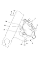
- the carrier 13 is shown in FIGS. 1 to 4 which are fixed to the mounting bracket 25 shown in FIGS. 1 to 4, the guide pin 26 shown in FIG. And a torque receiving pin 27.
- the mounting bracket 25 is disposed on the outer side (the side opposite to the wheel), which is one side of the disk 12, and is fixed to the non-rotating portion of the vehicle.
- the mounting bracket 25 includes a base portion 31 extending in the disc rotation direction, and a radial direction extending outward in the disc radial direction from the end portion of the base portion 31 on the disc insertion side. And an extending portion 32.
- a mounting hole 33 is formed in the base portion 31 at the end on the disk insertion side so as to penetrate in the disk axial direction.
- a mounting hole 34 is formed on the disk delivery side of the base portion 31 so as to penetrate in the disk axial direction.
- the carrier 13 is mounted on the vehicle with a mounting bolt (not shown) in which a fixing portion 35 around the mounting hole 33 and a fixing portion 36 around the mounting hole 34 are screwed into the mounting holes 33 and 34, respectively. Fixed to the non-rotating part.
- a guide pin mounting hole 38 is formed at one position through the disk axial direction at an intermediate position of the base portion 31 in the disk rotation direction, in other words, between the mounting hole 33 and the mounting hole 34.
- the mounting bracket 25 is formed with a torque receiving pin mounting hole 39 shown in FIG. 4 at one end in the disk axial direction at the end of the radially extending portion 32 on the outer side in the disk radial direction.
- the center of the torque receiving pin mounting hole 39 is disposed outside the disk 12 in the disk radial direction.
- the torque receiving pin mounting hole 39 is disposed on the outer side in the disk radial direction than the guide pin mounting hole 38 and on the disk insertion side.
- the outer shape of the mounting bracket 25 is formed by, for example, punching a metal plate material by press molding.
- mounting holes 33 and 34, guide pin mounting holes 38, and torque receiving pin mounting holes 39 are formed in the punched plate material by cutting or the like.
- the mounting bracket 25 does not undergo any bending process on the plate material, and has a shape with a constant thickness with no protrusions in the plate thickness direction.
- the guide pin 26 has, in order from one end in the axial direction, a small-diameter fixed shaft portion 42, an intermediate shaft portion 43 having a larger diameter than the fixed shaft portion 42, and a larger diameter than the intermediate shaft portion 43.
- the flange portion 44 and a guide shaft portion 45 having a smaller diameter than the intermediate shaft portion 43 are provided.
- the guide pin 26 is made of metal, and only one guide pin 26 is provided in the carrier 13.
- the guide pin 26 protrudes to the opposite side (outer side) from the disk 12 as a whole, and its fixed shaft portion 42 is fitted and fixed to the guide pin mounting hole 38 of the mounting bracket 25. In the state of being attached to the mounting bracket 25 as described above, the guide pin 26 protrudes from the mounting bracket 25 to the side opposite to the disk 12 along the disk axial direction.
- the torque receiving pin 27 includes, in order from one end in the axial direction, a torque receiving shaft portion 48 having a circular cross section having a constant diameter, and a fixed shaft portion (fixing portion) 49 having a larger diameter than the torque receiving shaft portion 48. And an intermediate shaft portion 50 having a larger diameter than the fixed shaft portion 49, a flange portion 51 having a larger diameter than the intermediate shaft portion 50, and a guide shaft portion 52 having a smaller diameter than the fixed shaft portion 49.
- the torque receiving pin 27 is made of metal, and only one is provided in the carrier 13.
- the torque receiving pin 27 is fixed by fitting the fixed shaft portion 49 into the torque receiving pin mounting hole 39 of the mounting bracket 25.
- the 48 side extends to the disk 12 side across the disk 12, and the other guide shaft portion 52 side extends to the opposite side of the disk 12.
- the torque receiving pin 27 extends from the mounting bracket 25 to the disk 12 side and both sides opposite to the disk 12, and from the outer side, which is one surface side of the disk 12, to the inner side, which is the other surface side of the disk 12. Extends beyond the disk 12.
- the torque receiving pin 27 is arranged on the disk insertion side in the carrier 13 depending on the formation position of the torque receiving pin mounting hole 39, and on the disk insertion side and on the disk radial direction outer side than the guide pin 26. Has been placed.
- the caliper 14 is slidable in the disk axial direction with respect to the carrier 13 by a guide shaft portion 52 of the torque receiving pin 27 and a guide shaft portion 45 of the guide pin 26 as shown in FIG. Supported by That is, the caliper 14 is a so-called pin slide type caliper. As shown in FIG. 2, the caliper 14 includes a caliper body 55, two pistons 56 and 57, and a pad pin 58.
- the caliper body 55 is formed by being integrally formed by casting from an aluminum alloy or the like and then being machined.
- the caliper body 55 is slidably attached to the torque receiving pin 27 shown in FIG. 1 and the guide pin 26 shown in FIG. 3 of the carrier 13 while straddling the disk 12 as shown in FIGS. .
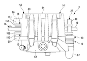
- the caliper body 55 includes a cylinder portion 62 disposed on the outer side of the carrier 13, a bridge portion 63 extending from the outer side of the cylinder portion 62 in the disk radial direction to the inner side of the disk 12, and a bridge It has a claw portion 64 extending radially inward of the disk 12 so as to face the cylinder portion 62 from the inner end portion of the portion 63.
- a sliding guide portion 66 is formed in the cylinder portion 62 so as to protrude inward in the disc radial direction from an intermediate position in the disc circumferential direction. Further, a sliding guide portion 67 is formed in the cylinder portion 62 so as to protrude from the outer side in the disk radial direction to the disk insertion side.
- a guide pin support hole 68 shown in FIG. 3 is formed in the sliding guide portion 66 so as to penetrate in the disk axial direction.
- a torque receiving pin support hole 69 shown in FIG. 1 is formed in the sliding guide portion 67 from the disk 12 side to a midway position in the disk axial direction.
- the boot 18 described above is fitted into the guide pin support hole 68 of the cylinder portion 62.
- the sliding guide portion 66 is slidably supported by the guide shaft portion 45 of the guide pin 26 via the boot 18.
- the guide shaft portion 52 of the torque receiving pin 27 is fitted in the torque receiving pin support hole 69 of the cylinder portion 62.
- the sliding guide portion 67 is slidably supported on the guide shaft portion 52 of the torque receiving pin 27.
- the sliding guide portion 66 and the sliding guide portion 67 are slidably guided by inserting the guide shaft portion 45 and the torque receiving pin 27 into the inside, but this is the embodiment of the present invention.
- the sliding guide portion 66 and the sliding guide portion 67 may be configured in a pin shape so that a hole is provided in the center portion of the guide shaft portion 45 and the torque receiving pin 27.
- the boot 18 is made of rubber. As shown in FIG. 3, the boot 18 is fitted into a locking portion 72 that is locked to the intermediate shaft portion 43 and the flange portion 44 of the guide pin 26, a telescopic bellows portion 73, and a guide pin support hole 68. In addition, a cylindrical portion 75 having a sliding hole 74 on the inside and a lid portion 76 covering the opposite side of the flange portion 44 of the guide shaft portion 45 are provided. The boot 18 is held in the guide pin support hole 68 of the caliper 14 by the cylindrical portion 75, and can slide the guide shaft portion 45 of the guide pin 26 of the carrier 13 in the sliding hole 74 inside the cylindrical portion 75. To fit.
- the boot 19 shown in FIG. 1 is also made of rubber.
- the boot 19 includes a locking portion 80 shown in FIG. 1 that is locked to the intermediate shaft portion 50 and the flange portion 51 shown in FIG. 5 of the torque receiving pin 27, and a guide shaft portion 52 that protrudes from the torque receiving pin support hole 69. It has a retractable bellows 81 that covers it.
- the caliper body 55 is supported by the guide pins 26 and the torque receiving pins 27 provided on the carrier 13 so as to be slidable in the direction along the disk axial direction.
- the torque receiving pin 27 extends from a fixed shaft portion 49 that is a fixed portion to the carrier 16 in a direction away from the disk 12 in the disk axis direction, and is a portion of the guide shaft that slidably supports the caliper 14. Part 52.
- two bottomed bores 87 and 88 are formed side by side in the disc rotation direction along the disc axial direction so as to open toward the claw portion 64 as shown in FIG. .
- a pipe connection hole 89 that communicates with the bore 87 on the disk feed-in side and the bore 88 on the disk feed-out side is formed along the disk radial direction.
- a brake pipe (not shown) is connected to the pipe connection hole 89.
- An air bleeding bleeder plug 90 communicating with the bore 88 is attached to the disk delivery side of the cylinder portion 62.
- the claw portion 64 has recesses 91 and 92 for allowing a cutting tool to pass when the bores 87 and 88 are machined. It is formed on the inlet side and the disk outlet side.
- a delivery side projecting portion 95 projecting from the bridge portion 63 is formed on the disc delivery side outside the disc radial direction.
- a delivery side projecting portion 96 projecting from the bridge portion 63 on the disc delivery side is formed on the outer side in the disc radial direction.
- the pistons 56 and 57 are slidably fitted into the bores 87 and 88 of the cylinder portion 62 as shown in FIG. In this fitted state, the pistons 56 and 57 are arranged side by side with respect to the caliper body 55 in the disk rotation direction.
- the pistons 56 and 57 are made of metal.
- the pad pin 58 is fitted into a through-hole extending in the disk axial direction provided in the delivery side projection 95 and the delivery side projection 96 of the caliper body 55.
- the pad pin 58 has a guide shaft portion 101 having a circular cross section having a constant diameter and disposed between the drawing-side projection 95 and the drawing-side projection 96 in this fitted state.
- the pad pin 58 is made of metal and extends along the disk axial direction, and the guide shaft portion 101 is disposed so as to straddle the disk 12 on the outer side in the disk radial direction than the disk 12 and on the disk delivery side from the bridge portion 63. ing.
- the line connecting the center position of this line and the center of the disk 12 (hereinafter referred to as the disk center) is orthogonal.
- the pair of friction pads 15 and 16 are disposed on both surfaces of the disk 12 and supported by the torque receiving shaft portion 48 of the torque receiving pin 27 and the guide shaft portion 101 of the pad pin 58.
- the friction pad 15 is disposed on the outer side which is one surface side of the disk 12
- the friction pad 16 is disposed on the inner side which is the other surface side of the disk 12.
- the outer friction pad 15 includes a friction material 106 that generates frictional resistance by contacting the disk 12, and a metal plate-like back metal 107 that holds the friction material 106. ing.
- the back plate 107 of the friction pad 15 includes a main plate portion 108 to which the friction material 106 is fixed to the surface on the disk 12 side, and a main plate portion 108 on the outer side in the disk radial direction as shown in FIG. From the disk entry side, the end protrusion 109 projecting obliquely to the disk entry side and the disk radial direction outside, and the disk delivery side and the disk radial direction from the disk delivery side outside the disk radial direction of the main plate portion 108 It has the edge part protrusion part 110 which protrudes diagonally outside.
- the back metal 107 of the friction pad 15 includes a protrusion 111 that protrudes radially outward from the end protrusion 109 side of the outer edge of the main plate 108 in the radial direction of the disk and an end protrusion of the outer edge of the main plate 108 in the radial direction of the disk. And a protrusion 112 protruding radially outward from the 110 side.
- the insertion hole 115 includes a plane portion 116 (a lower plane portion in FIG. 6), a plane portion 117 (an upper plane portion in FIG. 6), a plane portion 118 (a right plane portion in FIG. 6), and a plane portion. 119 (the flat portion on the left side in FIG. 6).
- the flat portion 116 is located at the center in the disk circumferential direction (the center in the left-right direction in the drawing) on the inner side in the disk radial direction, along the disk axial direction, and the center of the friction material 106 (hereinafter referred to as the pad center) and the disk center. It is formed along the direction orthogonal to the connecting line.
- the flat surface portion 117 is formed at the center in the disk circumferential direction outside the disk radial direction, along the disk axial direction, and along the direction perpendicular to the line connecting the pad center and the disk center.
- the flat surface portion 118 is formed at the center in the disk radial direction on the disk insertion side, along the disk axial direction, and along a line connecting the pad center and the disk center.
- the flat surface portion 119 is formed at the center in the disk radial direction on the disk delivery side, along the disk axial direction, and along a line connecting the pad center and the disk center.
- the torque receiving shaft portion 48 of the torque receiving pin 27 is inserted into the insertion hole 115.
- the insertion holes 115 can come into contact with the circular torque receiving shaft portion 48 at the four flat portions 116 to 119.
- the end protrusion 110 is formed with a long engagement hole (engagement portion) 122 extending in the disk axial direction along the disk circumferential direction. That is, the engagement hole 122 is formed in the friction pad 15 on the disk delivery side, which is a part other than the insertion hole 115.
- the engagement hole 122 includes a plane portion 123 (a lower plane portion in FIG. 6), a plane portion 124 (an upper plane portion in FIG. 6), a curved surface portion 125 (a curved surface portion on the right side in FIG. 6), and a curved portion. And a surface portion 126 (a curved portion on the left side in FIG. 6).
- the flat surface portion 123 is formed on the inner side in the disk radial direction, along the disk axial direction, and along the direction orthogonal to the line connecting the pad center and the disk center.
- the flat surface portion 124 is formed on the outer side in the disk radial direction, along the disk axial direction, and along the direction orthogonal to the line connecting the pad center and the disk center.
- the curved surface portion 125 is formed in a semicircular shape along the disk axial direction on the disk insertion side.
- the curved surface portion 126 is formed in a semicircular shape along the disk axial direction on the disk delivery side. Then, the guide shaft portion 101 of the pad pin 58 is inserted into the engagement hole 122.
- the flat surface portion 123 and the surface portion 124 parallel to the flat portion 123 can come into contact with the circular guide shaft portion 101 of the circular pad pin 58.
- the engagement hole 122 is provided with a predetermined gap on both sides in the disk rotation direction so that the curved surface portions 125 and 126 do not contact the pad pin 58. It should be noted that this gap need only be provided at least on the disk entry side.
- the pair of friction pads 15 and 16 has a line connecting the center of the engagement hole 122 and the center of the insertion hole 115 connecting the center of the pad and the center of the disk.
- the engagement hole 122 has a torque that is approximately twice the distance between the center of the torque receiving pin 27 and the center of the circumferential length of the friction pad 15 in the friction pad 15. It is formed at a position away from the center of the receiving pin 27.
- the friction pad 15 has a center in the circumferential direction of the disk that is aligned with a center of a line segment connecting the insertion hole 115 and the engagement hole 122 in the circumferential direction of the disk.
- the friction pad 15 on the outer side is slidably supported by the torque receiving shaft portion 48 of the torque receiving pin 27 of the carrier 13 in the insertion hole 115 formed on the disk insertion side.
- the engagement hole 122 formed on the delivery side is supported by the guide shaft portion 101 of the pad pin 58, and the torque receiving shaft portion 48 and the guide shaft portion 101 guide the sliding in the disk axis direction.
- the friction pad 15 abuts against the pad spring 17 shown in FIG. 3 at the protrusions 111 and 112, and is biased diagonally by the pad spring 17 toward the inner side in the disk radial direction and the disk delivery side.
- the inner friction pad 16 has a mirror surface through the disk 12 with respect to the outer friction pad 15.
- the inner side friction pad 16 uses a back metal 107 common to the outer side friction pad 15, and the friction material 106 common to the outer side friction pad 15 is placed on the reverse side of the back metal 107. It is configured to be fixed. That is, the back metal 107 is a common component shared by the outer friction pad 15 and the inner friction pad 16.
- the friction material 106 is also fixed to the back plate 107 of the inner friction pad 16 on the surface of the main plate portion 108 on the disk 12 side.
- the back metal 107 is formed with an insertion hole 115 in an end protruding portion 109 protruding from the main plate portion 108 to the disk insertion side, and an end portion protruding from the main plate portion 108 to the disk supply side.
- Engagement holes 122 are formed in the projecting portion 110, and projecting portions 111 and 112 projecting radially outward from the main plate portion 108 are formed.
- the inner friction pad 16 also receives the same torque receiving force as that for supporting the outer friction pad 15 so as to be able to come into contact with the flat portions 116 to 119 in the insertion hole 115 formed on the disk insertion side.
- a circular torque receiving shaft portion 48 of the pin 27 is inserted.
- the outer side friction pad 15 is supported so that it can be brought into contact with the flat portions 123 and 124 in the engagement hole 122 formed on the disk delivery side, which is a part other than the insertion hole 115.
- the circular guide shaft portion 101 of the same pad pin 58 as that to be inserted is inserted while forming a predetermined gap on both sides of the disk rotation direction.
- a torque receiving shaft portion 48 which is a portion where the pair of friction pads 15, 16 slide, has a circular shape.
- the engagement hole 122 has a torque receiving pin that is approximately twice the distance between the center of the torque receiving pin 27 and the center of the circumferential length of the friction pad 16. 27 is formed at a position away from the center of 27. Specifically, the friction pad 16 has the center in the circumferential direction of the disk aligned with the center of the line segment connecting the insertion hole 115 and the engagement hole 122 in the circumferential direction of the disk.
- the inner friction pad 16 is also supported by the torque receiving shaft portion 48 of the torque receiving pin 27 of the carrier 13 so that the insertion hole 115 formed on the disk insertion side is slidable.
- the exit-side engagement hole 122 is supported by the guide shaft portion 101 of the pad pin 58, and the torque receiving pin 27 and the pad pin 58 guide the sliding in the disk axis direction.
- the back metal 107 of the inner friction pad 16 is also biased obliquely by the pad spring 17 toward the inner side in the disk radial direction and the disk delivery side by the pad spring 17.
- the carrier 13 is provided with one torque receiving pin 27 on which the pair of friction pads 15 and 16 slide on the disk insertion side.
- the pair of friction pads 15, 16 are formed with insertion holes 115 through which the torque receiving pins 27 are inserted on the respective disk insertion sides, and engaging portions that engage with the caliper 14 at portions other than the insertion holes 115.
- a certain engagement hole 122 is formed.
- Both the outer side friction pad 15 and the inner side friction pad 16 are not supported by the mounting bracket 25, and the torque receiving pin 27 attached to the mounting bracket 25 and the pad pin attached to the caliper 14. Only 58 is supported.
- a claw portion 64 of the caliper 14 is arranged on the side of the inner friction pad 16 opposite to the disc 12, and a cylinder portion 62 of the caliper 14 is arranged on the side of the outer friction pad 15 opposite to the disc 12. Is done.
- the caliper body 55 slides on the guide shaft portion 45 of the guide pin 26 and the guide shaft portion 52 of the torque receiving pin 27 so as to move the claw portion 64 to the disk 12 side.
- the friction pad 16 is pressed.
- the inner friction pad 16 slides on the guide shaft portion 101 of the torque receiving pin 27 and the torque receiving shaft portion 48 of the pad pin 58 to contact the disk 12.
- the pair of friction pads 15 and 16 provided on both surfaces of the disk 12 are brought into contact with the disk 12, and the disk 12, that is, the wheel is braked by the frictional resistance.
- braking torque is generated from the disk insertion side to the disk extraction side in the pair of friction pads 15 and 16.
- One torque receiving pin 27 on the disk insertion side receives the braking torque in the disk rotation direction from the flat portions 117 and 118 of the insertion hole 115 that abuts on the torque receiving pin 27.
- the pad pin 58 of the caliper 14 supports the pair of friction pads 15 and 16 by the engagement hole 122 that is long in the disk rotation direction.
- the engagement hole 122 and the pad pin 58 include the disk rotation direction. Is provided with a predetermined gap so as not to receive braking torque from the pair of friction pads 15 and 16.
- the disc brake 11 is a pull type disc brake that receives the braking torque during braking on the disc entry side, and the braking torque generated in the pair of friction pads 15 and 16 during braking when the vehicle is moving forward. Only one torque receiving pin 27 on the disk insertion side is configured to receive.
- FIG. 8 shows an example of an attachment state of the disc brake 11 according to the present embodiment to the vehicle.
- the front fork 130 provided in the two-wheeled vehicle is inclined rearwardly.
- Two caliper supports, a lower caliper support 131 and an upper caliper support 132, are provided at the rear portion of the front fork 130.
- a mounting portion 133 is provided at the rear end of the caliper support 131.
- a mounting portion 134 is provided at the rear end of the caliper support 132.
- the disc brake 11 is bolted to the mounting portions 133 and 134 at the fixing portions 35 and 36 of the carrier 13 described above, and is disposed behind the front fork 130.
- the caliper supports 131 and 132 including the attachment portions 133 and 134 are non-rotating portions of the vehicle that do not rotate like wheels.
- the extending portion extending in the same direction from both ends of the base portion 136.
- a U-shaped carrier 139 having 137 and 138 may be used.
- the guide pin 26 and the torque receiving pin 27 are provided at the respective ends of the extending portions 137 and 138 of the carrier 139.
- both ends of the base portion 136 may be bolted to the attachment portions 143 and 144 at the tips of the two caliper supports 141 and 142 at the front portion of the front fork 140. In this case, a small carrier 139 can be obtained.
- a T-shaped groove is formed on the disc insertion side when the carrier that supports the caliper moves forward in the vehicle.
- the groove has a structure in which a T-shaped protrusion of the friction pad is engaged, and the torque generated in the friction pad during braking is received by the T-shaped groove of the carrier.
- the surface pressure during braking can be made uniform by lowering the surface pressure on the disk insertion side, thereby improving the brake noise suppression performance.
- the structure that receives the braking torque by the T-shaped groove of the carrier has a problem that the shape of the groove and the shape of the protrusion of the friction pad are complicated, and the productivity is not good. Further, since the surface pressure of the friction pad during braking is not stable, there is a problem that the friction pad wears unevenly or brake noise is generated.
- the pair of friction pads 15 and 16 are slid by the single torque receiving pin 27 disposed on the disc insertion side of the carrier 13, and the single torque receiving pin 27.
- it receives a braking torque in the disc rotation direction generated in the pair of friction pads 15 and 16 during braking when the vehicle is moving forward. Therefore, since the braking torque is received on the disk entry side, the self-servo effect does not occur. For this reason, the surface pressure on the disk entry side of the friction pads 15 and 16 during braking can be reduced, and the surface pressure can be made uniform. Accordingly, uneven wear of the friction pads 15 and 16 can be reduced, so that the life of the friction pads 15 and 16 can be increased, the amount of brake operation can be reduced, and the brake operation feeling can be improved. Moreover, brake squeal can be suppressed.
- one torque receiving pin 27 receives the braking torque in the disk rotation direction generated in the pair of friction pads 15 and 16 during braking when the vehicle moves forward, the structure is simplified and productivity is improved. be able to.
- the shape of the mounting bracket 25 can be simplified and the productivity can be improved.
- the back metal 107 can be shared by the friction pads 15 and 16, the types of parts can be reduced, and the manufacturing cost and the management cost can be reduced.
- the disc rotation is performed so that the pad pin 58 supported by the caliper 14 and the engagement hole 122 formed on the disc delivery side of each of the pair of friction pads 15 and 16 do not receive the braking torque when the vehicle moves forward.
- a predetermined gap is provided in the direction. For this reason, since the role that the pad pin 58 supports the friction pads 15 and 16 is clarified, the caliper 14 including the pad pin 58 can be reduced in size and simplified.
- the engagement hole 122 is provided in each of the pair of friction pads 15 and 16 by a distance approximately twice as long as the distance between the center of the torque receiving pin 27 and the center of the friction pad 15 and 16 in the circumferential direction. It is formed at a position away from the center of. For this reason, it is possible to reduce the load on the pad pin 58 while reducing the size of the friction pads 15 and 16 as a whole, and to reduce the size of the pad pin 58.
- one torque receiving pin 27 receives the braking torque of the pair of friction pads 15 and 16 at a torque receiving shaft portion 48 which is a circular portion. For this reason, it is possible to easily reduce the load on the pad pin 58 and reduce the size of the pad pin 58 while reducing the size of the entire friction pads 15 and 16 as described above.
- the disc brake 11 is a pull type in which the torque receiving pin 27 is disposed on the disk insertion side, and the torque receiving shaft portion 48 of the torque receiving pin 27 has a round cross section.
- the following conditions are met. That is, (1) The angle ⁇ formed by the direction of the force F applied to the friction pads 15 and 16 and the direction of the force Ft applied to the torque receiving pin 27, and the direction of the component force Fd in the direction orthogonal to the direction of the force F and the force Ft
- the relationship between the angle ⁇ and the angle ⁇ is ⁇ ⁇ .
- the pad pin 58 can be further reduced in size and simplified.
- the pair of friction pads 15 and 16 has a center in the disk circumferential direction, a center of a line segment connecting the insertion hole 115 through which the torque receiving pin 27 is inserted and the engagement hole 122 through which the pad pin 58 is inserted, and the disk circumferential direction.
- the position matches. For this reason, it is possible to reduce the load on the pad pin 58 while reducing the size of the friction pads 15 and 16 as a whole, and to reduce the size of the pad pin 58.
- one torque receiving pin 27 is a guide shaft portion 52 that extends from a fixed shaft portion 49 that is a fixed portion to the carrier 13 and supports the caliper 14 so as to be slidable, thereby suppressing the influence of braking torque.
- the caliper 14 can be slidably supported by the torque receiving pins 27. This is the direction in which the guide shaft portion 52 extends away from the disk 12 in the disk axis direction, and extends in the disk axis direction across the disk 12 to increase the braking torque of the pair of friction pads 15 and 16. This is because the torque receiving shaft portion 48 is in the opposite direction. Therefore, the structure is further simplified and the productivity can be further improved.
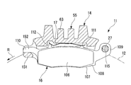
- the caliper 14 is not provided with the pad pin 58 of the first embodiment.
- the caliper 14 is formed with a slide base 150 that protrudes toward the disk 12 along the disk axis direction on the delivery-side protrusion 95, and to the disk 12 side along the disk axis direction at the delivery-side protrusion 96.
- a protruding slide base 151 is formed.
- an engaging portion 152 that engages with the slide base portions 150 and 151 of the caliper 14 is formed on the end protruding portion 110 of the common back plate 107 of the friction pads 15 and 16. And this engaging part 152 slides on the slide base parts 150 and 151 along the disk radial direction outer side. As a result, the friction pads 15 and 16 are prevented from rotating and slide. That is, the pair of friction pads 15, 16 are formed with insertion holes 115 through which the torque receiving pins 27 are inserted on the respective disk insertion sides, and engaging portions 152 that engage with the caliper 14 at portions other than the insertion holes 115. Is formed.
- the number of parts and the manufacturing cost can be reduced because the pad pin is not necessary.
- the carrier configured to be fixed to the non-rotating portion of the vehicle, and the pair of friction pads that are slidably supported by the carrier and disposed on both sides of the disc
- a disc brake having a piston that presses one friction pad of the pair of friction pads and a caliper that is slidably supported by the carrier. And a torque receiving pin that extends in the axial direction of the disk across the disk and on which the pair of friction pads slide.
- insertion holes through which the torque receiving pins are inserted are formed on the respective disk insertion sides, and engaging portions that are engaged with the calipers are formed at portions other than the insertion holes. .
- One torque receiving pin on the disk entry side is configured to receive a braking torque in the disk rotation direction generated in the pair of friction pads during braking when the vehicle moves forward.
- a pair of friction pads are slid by one torque receiving pin arranged on the disk entrance side of the carrier, and this one torque receiving pin is applied to the pair of friction pads during braking when the vehicle moves forward.
- the generated braking torque in the disk rotation direction is received. Therefore, since the torque at the time of braking is received on the disk entry side, the self-servo effect does not occur, so the surface pressure on the disk entry side of the friction pad during braking can be reduced and the surface pressure can be made uniform. .
- one torque receiving pin receives a braking torque in the disk rotation direction generated in the pair of friction pads during braking when the vehicle moves forward. For this reason, a structure becomes simple and productivity can be improved. In particular, it is not necessary to form a torque receiving portion on the carrier mounting bracket. For this reason, the shape of a mounting bracket can be simplified and productivity can be improved.
- the backing metal of both friction pads can be shared. In this case, the types of parts can be reduced, and the manufacturing cost and the management cost can be reduced.
- the engagement portion is an engagement hole formed on the disk delivery side of each of the pair of friction pads when the vehicle moves forward, and through which a pad pin supported by the caliper is inserted.
- the engagement hole and the pad pin are provided with a predetermined gap in the disk rotation direction so as not to receive a braking torque when the vehicle moves forward.
- the engaging portion is separated from the center of the torque receiving pin by a distance of approximately twice the distance between the center of the torque receiving pin and the circumferential center of the friction pad.
- the engagement hole is formed in a position where the pad pin supported by the caliper is inserted.
- the pair of friction pads is characterized in that the center in the disk circumferential direction coincides with the center of a line segment connecting the insertion hole and the engagement hole in the disk circumferential direction.
- the one torque receiving pin is characterized in that a portion where the pair of friction pads slide is circular.
- the torque receiving pin has a portion that extends in a direction away from the disk in a disk axial direction from a fixed portion to the carrier and slidably supports the caliper. In this manner, the torque receiving pin is separated from the disk in the disk axial direction, as opposed to the portion receiving the braking torque of the pair of friction pads extending from the fixing portion to the carrier across the disk in the disk axial direction. Since the caliper is slidably supported at the portion extending in the direction, the caliper can be slidably supported by the torque receiving pin while suppressing the influence of the braking torque. Therefore, the structure is further simplified and the productivity can be further improved.
- one torque receiving pin receives the braking torque in the disk rotation direction generated in the pair of friction pads during braking when the vehicle moves forward, the structure is simplified and the productivity of the disk brake is improved. Can be improved. Further, since it is not necessary to form a torque receiving portion on the mounting bracket of the carrier, the shape of the mounting bracket can be simplified and the productivity of the disc brake can be improved.
Landscapes
- Engineering & Computer Science (AREA)
- General Engineering & Computer Science (AREA)
- Mechanical Engineering (AREA)
- Braking Arrangements (AREA)
Priority Applications (1)
| Application Number | Priority Date | Filing Date | Title |
|---|---|---|---|
| CN201180047646.XA CN103249959B (zh) | 2010-12-10 | 2011-12-08 | 盘形制动器 |
Applications Claiming Priority (2)
| Application Number | Priority Date | Filing Date | Title |
|---|---|---|---|
| JP2010276191A JP5879032B2 (ja) | 2010-12-10 | 2010-12-10 | ディスクブレーキ |
| JP2010-276191 | 2010-12-10 |
Publications (1)
| Publication Number | Publication Date |
|---|---|
| WO2012077754A1 true WO2012077754A1 (ja) | 2012-06-14 |
Family
ID=46207237
Family Applications (1)
| Application Number | Title | Priority Date | Filing Date |
|---|---|---|---|
| PCT/JP2011/078434 Ceased WO2012077754A1 (ja) | 2010-12-10 | 2011-12-08 | ディスクブレーキ |
Country Status (3)
| Country | Link |
|---|---|
| JP (1) | JP5879032B2 (enExample) |
| CN (1) | CN103249959B (enExample) |
| WO (1) | WO2012077754A1 (enExample) |
Cited By (1)
| Publication number | Priority date | Publication date | Assignee | Title |
|---|---|---|---|---|
| ITUA20162181A1 (it) * | 2016-03-31 | 2017-10-01 | Freni Brembo Spa | Pastiglia, assieme, pinza e metodo per freno a disco |
Families Citing this family (3)
| Publication number | Priority date | Publication date | Assignee | Title |
|---|---|---|---|---|
| JP6493309B2 (ja) * | 2016-05-31 | 2019-04-03 | 株式会社アドヴィックス | ブレーキキャリパ |
| TWI715264B (zh) * | 2018-12-26 | 2021-01-01 | 日商本田技研工業股份有限公司 | 碟煞及其製造方法 |
| JP7737814B2 (ja) * | 2021-05-20 | 2025-09-11 | ナブテスコ株式会社 | パッドホルダ及び鉄道車両用ブレーキキャリパ装置 |
Citations (4)
| Publication number | Priority date | Publication date | Assignee | Title |
|---|---|---|---|---|
| JPS5732231A (en) * | 1980-08-01 | 1982-02-20 | Baruresutora Chiimika Spa | Membrane type sulfonation and improved process for multi stage nutralization of sulfonic acid and device therefor |
| JPS6314029U (enExample) * | 1986-07-11 | 1988-01-29 | ||
| JPH07127674A (ja) * | 1993-11-05 | 1995-05-16 | Nissin Kogyo Kk | 車両用ディスクブレーキ |
| WO2010010583A1 (en) * | 2008-07-22 | 2010-01-28 | Freni Brembo S.P.A. | Pad for a brake caliper and brake caliper for a disc brake |
Family Cites Families (4)
| Publication number | Priority date | Publication date | Assignee | Title |
|---|---|---|---|---|
| JPS589005Y2 (ja) * | 1977-03-03 | 1983-02-18 | 日信工業株式会社 | オ−トバイのディスクブレ−キ装置 |
| US5499696A (en) * | 1993-07-27 | 1996-03-19 | Tokico Ltd. | Disk brake |
| JPH07208514A (ja) * | 1994-01-19 | 1995-08-11 | Tokico Ltd | ディスクブレーキ |
| JP2008196683A (ja) * | 2006-06-29 | 2008-08-28 | Akebono Brake Ind Co Ltd | ディスクブレーキ |
-
2010
- 2010-12-10 JP JP2010276191A patent/JP5879032B2/ja not_active Expired - Fee Related
-
2011
- 2011-12-08 CN CN201180047646.XA patent/CN103249959B/zh not_active Expired - Fee Related
- 2011-12-08 WO PCT/JP2011/078434 patent/WO2012077754A1/ja not_active Ceased
Patent Citations (4)
| Publication number | Priority date | Publication date | Assignee | Title |
|---|---|---|---|---|
| JPS5732231A (en) * | 1980-08-01 | 1982-02-20 | Baruresutora Chiimika Spa | Membrane type sulfonation and improved process for multi stage nutralization of sulfonic acid and device therefor |
| JPS6314029U (enExample) * | 1986-07-11 | 1988-01-29 | ||
| JPH07127674A (ja) * | 1993-11-05 | 1995-05-16 | Nissin Kogyo Kk | 車両用ディスクブレーキ |
| WO2010010583A1 (en) * | 2008-07-22 | 2010-01-28 | Freni Brembo S.P.A. | Pad for a brake caliper and brake caliper for a disc brake |
Cited By (2)
| Publication number | Priority date | Publication date | Assignee | Title |
|---|---|---|---|---|
| ITUA20162181A1 (it) * | 2016-03-31 | 2017-10-01 | Freni Brembo Spa | Pastiglia, assieme, pinza e metodo per freno a disco |
| US10690202B2 (en) | 2016-03-31 | 2020-06-23 | Freni Brembo S.P.A. | Pad, assembly, clamp and method for brake disc |
Also Published As
| Publication number | Publication date |
|---|---|
| CN103249959A (zh) | 2013-08-14 |
| JP2012122598A (ja) | 2012-06-28 |
| JP5879032B2 (ja) | 2016-03-08 |
| CN103249959B (zh) | 2017-03-08 |
Similar Documents
| Publication | Publication Date | Title |
|---|---|---|
| JP6208065B2 (ja) | 対向ピストン型ディスクブレーキ装置 | |
| JP5368528B2 (ja) | 静止用機械式ディスクブレーキ | |
| JP5847561B2 (ja) | ディスクブレーキ | |
| CN101852256B (zh) | 盘式制动设备 | |
| JP2006057718A (ja) | フローティングキャリパ型ディスクブレーキ | |
| US4068743A (en) | Disc brake support structure | |
| JP5879032B2 (ja) | ディスクブレーキ | |
| EP2971839B1 (en) | Tensioned brake pad | |
| CN110730876A (zh) | 盘式制动器 | |
| JP4474474B2 (ja) | ピンスライド型車両用ディスクブレーキ | |
| US8708111B2 (en) | Disk brake equipped reduced-size yoke | |
| JP5826091B2 (ja) | ディスクブレーキ | |
| JP2009133356A (ja) | フローティングキャリパ型ディスクブレーキ | |
| TWI703281B (zh) | 碟式制動器 | |
| WO2010137715A1 (ja) | 車両用ディスクブレーキ | |
| TWI664362B (zh) | Disc brake | |
| JP5544263B2 (ja) | ブレーキパッド | |
| JP2009008113A (ja) | ディスクブレーキ | |
| JP5677581B2 (ja) | ディスクブレーキ | |
| JP4955095B2 (ja) | 車両用ディスクブレーキ | |
| JP6134613B2 (ja) | ディスクブレーキ | |
| JP2012167739A (ja) | ディスクブレーキ | |
| CN104246271B (zh) | 盘式制动器 | |
| JP5603797B2 (ja) | 車両用ディスクブレーキ | |
| JP2009103144A (ja) | ディスクブレーキ |
Legal Events
| Date | Code | Title | Description |
|---|---|---|---|
| 121 | Ep: the epo has been informed by wipo that ep was designated in this application |
Ref document number: 11847129 Country of ref document: EP Kind code of ref document: A1 |
|
| NENP | Non-entry into the national phase |
Ref country code: DE |
|
| 122 | Ep: pct application non-entry in european phase |
Ref document number: 11847129 Country of ref document: EP Kind code of ref document: A1 |