WO2012074016A1 - 管状挿入システム - Google Patents
管状挿入システム Download PDFInfo
- Publication number
- WO2012074016A1 WO2012074016A1 PCT/JP2011/077693 JP2011077693W WO2012074016A1 WO 2012074016 A1 WO2012074016 A1 WO 2012074016A1 JP 2011077693 W JP2011077693 W JP 2011077693W WO 2012074016 A1 WO2012074016 A1 WO 2012074016A1
- Authority
- WO
- WIPO (PCT)
- Prior art keywords
- information
- bending
- amount
- unit
- shape
- Prior art date
Links
Images


Classifications
-
- A—HUMAN NECESSITIES
- A61—MEDICAL OR VETERINARY SCIENCE; HYGIENE
- A61B—DIAGNOSIS; SURGERY; IDENTIFICATION
- A61B1/00—Instruments for performing medical examinations of the interior of cavities or tubes of the body by visual or photographical inspection, e.g. endoscopes; Illuminating arrangements therefor
- A61B1/005—Flexible endoscopes
- A61B1/0051—Flexible endoscopes with controlled bending of insertion part
-
- A—HUMAN NECESSITIES
- A61—MEDICAL OR VETERINARY SCIENCE; HYGIENE
- A61B—DIAGNOSIS; SURGERY; IDENTIFICATION
- A61B1/00—Instruments for performing medical examinations of the interior of cavities or tubes of the body by visual or photographical inspection, e.g. endoscopes; Illuminating arrangements therefor
- A61B1/00002—Operational features of endoscopes
- A61B1/00004—Operational features of endoscopes characterised by electronic signal processing
- A61B1/00006—Operational features of endoscopes characterised by electronic signal processing of control signals
-
- A—HUMAN NECESSITIES
- A61—MEDICAL OR VETERINARY SCIENCE; HYGIENE
- A61B—DIAGNOSIS; SURGERY; IDENTIFICATION
- A61B1/00—Instruments for performing medical examinations of the interior of cavities or tubes of the body by visual or photographical inspection, e.g. endoscopes; Illuminating arrangements therefor
- A61B1/005—Flexible endoscopes
- A61B1/0051—Flexible endoscopes with controlled bending of insertion part
- A61B1/0052—Constructional details of control elements, e.g. handles
-
- A—HUMAN NECESSITIES
- A61—MEDICAL OR VETERINARY SCIENCE; HYGIENE
- A61B—DIAGNOSIS; SURGERY; IDENTIFICATION
- A61B1/00—Instruments for performing medical examinations of the interior of cavities or tubes of the body by visual or photographical inspection, e.g. endoscopes; Illuminating arrangements therefor
- A61B1/005—Flexible endoscopes
- A61B1/009—Flexible endoscopes with bending or curvature detection of the insertion part
-
- G—PHYSICS
- G02—OPTICS
- G02B—OPTICAL ELEMENTS, SYSTEMS OR APPARATUS
- G02B23/00—Telescopes, e.g. binoculars; Periscopes; Instruments for viewing the inside of hollow bodies; Viewfinders; Optical aiming or sighting devices
- G02B23/24—Instruments or systems for viewing the inside of hollow bodies, e.g. fibrescopes
- G02B23/2476—Non-optical details, e.g. housings, mountings, supports
-
- A—HUMAN NECESSITIES
- A61—MEDICAL OR VETERINARY SCIENCE; HYGIENE
- A61B—DIAGNOSIS; SURGERY; IDENTIFICATION
- A61B1/00—Instruments for performing medical examinations of the interior of cavities or tubes of the body by visual or photographical inspection, e.g. endoscopes; Illuminating arrangements therefor
- A61B1/00002—Operational features of endoscopes
- A61B1/00043—Operational features of endoscopes provided with output arrangements
-
- A—HUMAN NECESSITIES
- A61—MEDICAL OR VETERINARY SCIENCE; HYGIENE
- A61B—DIAGNOSIS; SURGERY; IDENTIFICATION
- A61B17/00—Surgical instruments, devices or methods, e.g. tourniquets
- A61B17/00234—Surgical instruments, devices or methods, e.g. tourniquets for minimally invasive surgery
- A61B2017/00292—Surgical instruments, devices or methods, e.g. tourniquets for minimally invasive surgery mounted on or guided by flexible, e.g. catheter-like, means
- A61B2017/003—Steerable
- A61B2017/00318—Steering mechanisms
- A61B2017/00323—Cables or rods
- A61B2017/00327—Cables or rods with actuating members moving in opposite directions
-
- A—HUMAN NECESSITIES
- A61—MEDICAL OR VETERINARY SCIENCE; HYGIENE
- A61B—DIAGNOSIS; SURGERY; IDENTIFICATION
- A61B34/00—Computer-aided surgery; Manipulators or robots specially adapted for use in surgery
- A61B34/20—Surgical navigation systems; Devices for tracking or guiding surgical instruments, e.g. for frameless stereotaxis
- A61B2034/2046—Tracking techniques
- A61B2034/2061—Tracking techniques using shape-sensors, e.g. fiber shape sensors with Bragg gratings
Definitions
- the present invention relates to a tubular insertion system.
- the endoscope has an insertion part.
- the distal end portion of the insertion portion has a measurement portion that measures the strength when the insertion portion is inserted.
- a measurement unit is, for example, a strain gauge (pressure sensor).
- Patent Document 1 Such an endoscope is disclosed in Patent Document 1, for example.
- a pressure-sensitive sensor that is a measurement unit is disposed at a distal end portion of an insertion unit such as an endoscope or a catheter.
- the pressure sensor detects the amount of force (pressure sensitive information).
- This detection result is used for operation as operation support information indicating operation support when the insertion unit is inserted and when the insertion unit is curved.
- This operation includes an insertion operation of the insertion portion, a twisting operation of the insertion portion, a bending operation of the insertion portion, and the like.
- This operation support information is very important when operating the insertion section.
- Patent Document 1 in order for the operator to easily insert the insertion portion, the operator needs to accurately and accurately grasp the pressure sensitive information at the distal end portion indicating the operation support information. In order for the operator to insert the insertion portion more easily, it is desirable for the operator to know operation support information such as shape information of the insertion portion in addition to the pressure sensitive information. In order for the operator to acquire such operation support information (shape information of the insertion portion), the operator needs to accurately grasp the pressure sensitive information from all directions. For this reason, in Patent Document 1 described above, it is preferable that the pressure-sensitive sensors are arranged so as to be distributed over the entire distal end portion of the insertion portion.
- the present invention has been made in view of these circumstances, and an object thereof is to provide a tubular insertion system that can easily obtain operation support information with high accuracy.
- One aspect of the tubular insertion system of the present invention detects an insertion portion having a bending portion that bends, a bending operation mechanism that operates the bending portion to bend the bending portion, and an operation of the bending operation mechanism.
- a bending operation amount detection calculation mechanism that calculates bending operation amount information indicating the amount of operation;
- a bending shape detection calculation mechanism that detects a bending shape of the bending portion and calculates bending shape information indicating the bending shape;
- a first operation support information acquisition unit configured to acquire first operation support information indicating support for operation of the bending unit based on at least one of the bending operation amount information and the bending shape information;
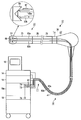
- FIG. 1 is a schematic configuration diagram of a tubular insertion system according to the present invention.
- FIG. 2A is a diagram for explaining a bending operation amount detection calculation mechanism.
- FIG. 2B is a diagram for explaining a bending operation amount detection calculation mechanism.
- FIG. 2C is a diagram for explaining a relationship between a read unit and a bending operation amount detection unit arranged in the bending operation unit.
- FIG. 2D is a diagram for explaining a relationship between a read unit and a bending operation amount detection unit arranged in the bending operation unit.
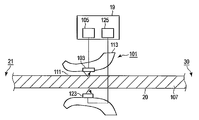
- FIG. 3A is a diagram for explaining a curved shape detection calculation mechanism.
- FIG. 3B is a diagram for explaining a curved shape detection calculation mechanism.
- FIG. 4A is a diagram illustrating a state where the insertion portion is inserted into the body cavity by the insertion assisting tool.
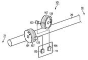
- FIG. 4B is a diagram for explaining an insertion / extraction twisting operation detection calculation mechanism.
- FIG. 4C is a diagram for explaining the insertion / extraction twisting operation detection calculation mechanism.
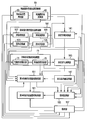
- FIG. 5 is a diagram for explaining a control system of the endoscope system.
- an endoscope system tubular insertion system 10 includes, for example, an endoscope 12 that images a desired observation object, and an image that performs image processing on the observation object captured by the endoscope 12.
- a processing device 14 for example, a video processor
- a monitor 16 that is connected to the image processing device 14, is a display unit that displays an observation target imaged by the endoscope 12 and image-processed by the image processing device 14. is doing.
- the endoscope system 10 emits light that emits illumination light toward the endoscope 12, and emits light that is different from the illumination light emitted from the light source device 18, and light emission detection that detects this light.
- the apparatus 18a has the control apparatus 19 which controls the endoscope system 10 containing the endoscope 12, the image processing apparatus 14, the monitor 16, the light source device 18, and the light emission detection apparatus 18a.
- the observation object is an affected part or a lesion part in a subject (for example, a body cavity (lumen)).
- the endoscope 12 includes a hollow elongate insertion portion 20 that is inserted into a body cavity of a patient, and an operation portion 30 that is connected to a proximal end portion of the insertion portion 20 and operates the endoscope 12.
- the endoscope 12 is a tubular insertion device that inserts a tubular insertion portion 20 into a body cavity.
- the insertion portion 20 includes a distal end hard portion 21, a bending portion 23 that bends, and a flexible tube portion 25 from the distal end side to the proximal end portion side of the insertion portion 20.
- the proximal end portion of the distal rigid portion 21 is connected to the distal end portion of the bending portion 23, and the proximal end portion of the bending portion 23 is connected to the distal end portion of the flexible tube portion 25.
- the distal end hard portion 21 is the distal end portion of the insertion portion 20 and the distal end portion of the endoscope 12 and is hard.
- the bending portion 23 is bent in a desired direction such as up, down, left, and right, for example, by an operation of a bending operation portion 37 described later.
- a bending operation portion 37 described later.
- the bending portion 23 is configured by connecting a node ring (not shown) so as to be rotatable along the longitudinal axis direction of the insertion portion 20.
- the flexible tube portion 25 has a desired flexibility and is bent by an external force.
- the flexible tube portion 25 is a tubular member that extends from a body portion 31 (described later) of the operation portion 30.
- the operation unit 30 includes a main body part 31 from which the flexible tube part 25 extends, a gripping part 33 that is connected to a base end part of the main body part 31 and is gripped by an operator who operates the endoscope 12, and a gripping part And a universal cord 41 connected to the terminal 33.
- the gripping portion 33 has a bending operation portion 37 that operates operation wires 38LR and 38UD described later in order to bend the bending portion 23.
- the bending operation section 37 includes a left / right bending operation knob 37LR for bending the bending section 23 left and right, an up / down bending operation knob 37UD for bending the bending section 23 up and down, and a fixed knob for fixing the position of the curved bending section 23. 37c.
- the left / right bending operation knob 37LR is connected to a left / right bending operation driving unit (not shown) driven by the left / right bending operation knob 37LR.
- the up / down bending operation knob 37UD is connected to an up / down bending operation driving unit (not shown) driven by the up / down bending operation knob 37UD.
- the up and down bending operation driving unit and the left and right bending operation driving unit are, for example, disposed in the grip portion 33.
- the bending operation drive unit in the left-right direction is connected to an operation wire 38LR that passes through the operation unit 30, the flexible tube unit 25, and the bending unit 23.
- the operation wire 38LR is connected to the distal end portion of the bending portion 23.
- the bending operation driving unit in the vertical direction is connected to an operation wire 38UD through which the operation unit 30, the flexible tube unit 25, and the bending unit 23 are inserted.
- the operation wire 38UD is different from the operation wire 38LR.
- the operation wire 38UD is connected to the distal end portion of the bending portion 23.
- the left / right bending operation knob 37LR bends the bending portion 23 in the left / right direction via the left / right bending operation driving portion and the operation wire 38LR.
- the up / down bending operation knob 37UD bends the bending portion 23 in the up / down direction via the up / down bending operation drive unit and the operation wire 38UD.
- Such a bending operation section 37 (left / right bending operation knob 37LR and up / down bending operation knob 37UD), left / right bending operation driving section, operation wire 38LR, up / down bending operation driving section, and operation wire 38UD
- a bending operation mechanism 39 that operates the bending portion 23.
- the universal cord 41 extends from the side surface of the grip portion 33.
- the universal cord 41 has a connector 42 that can be attached to and detached from the image processing device 14, the light source device 18, and the light emission detection device 18 a at the base end.
- the image processing device 14, the light source device 18, the light emission detection device 18a, and the control device 19 are connected to each other.
- the image processing device 14, the light source device 18, and the light emission detection device 18 a are detachably connected to the endoscope 12 through a connector 42.
- the endoscope system 10 detects the operation of the bending operation mechanism 39 and calculates bending operation amount information indicating the amount of operation.
- An operation amount detection calculation mechanism 61 and a bending shape detection calculation mechanism 71 that detects a bending shape (bending amount) of the bending portion 23 that is actually bent and calculates bending shape information indicating the bending shape. .
- the bending operation amount of the bending operation mechanism 39 is a bending operation in which the bending operation mechanism 39 is operated to bend the bending portion 23. Indicates the amount. Specifically, the bending operation amount of the bending operation mechanism 39 is a bending operation amount in which the operation wires 38LR and 38UD are operated as shown in FIG. 2A, or a bending in which the bending operation unit 37 is operated as shown in FIG. 2B. Indicates the operation amount.
- the bending operation amount detection calculation mechanism 61 is a bending operation amount detection unit 63 that detects a bending operation amount of the bending operation mechanism 39, and a bending operation amount that calculates bending operation amount information based on the detection result of the bending operation amount detection unit 63. And an arithmetic unit 65.
- the base end portion of the operation wire 38LR and the base end portion of the operation wire 38UD are linear, for example.
- a read portion 67 such as a scale is provided.
- the read section 67 moves together with the operation wires 38LR and 38UD as the operation wires 38LR and 38UD move.
- the bending operation amount detection unit 63 reads the read portion 67 that moves together with the operation wires 38LR and 38UD, and detects the movement of the read portion 67.
- the bending operation amount detection unit 63 detects the movement of the operation wires 38LR and 38UD.
- the bending operation amount detection unit 63 is a linear encoder, for example, and is disposed inside the operation unit 30, for example.
- the bending operation amount calculation unit 65 detects the movement amount of the read portion 67, that is, the movement amount of the operation wire 38LR and the operation wire 38UD, based on the detection result detected by the bending operation amount detection unit 63. Then, the bending operation amount calculator 65 calculates bending operation amount information of the operation wire 38LR and the operation wire 38UD based on the detection result. The bending operation amount calculator 65 calculates the bending operation amount information of the operation wire 38LR and the operation wire 38UD, thereby detecting the bending operation amount of the bending operation mechanism 39 and calculating the bending operation amount information.
- the bending operation amount calculation unit 65 is disposed, for example, in the control device 19 as shown in FIGS. 1 and 2A.
- the bending operation amount detection calculation mechanism 61 detects the bending operation amount of the bending operation mechanism 39 based on the movement amount of the operation wires 38LR and 38UD in the bending operation mechanism 39, and calculates the bending operation amount information.
- the read section 67 may be disposed on the left / right bending operation knob 37LR and the up / down bending operation knob 37UD.
- the read portion 67 is disposed, for example, on the outer peripheral surface of the cylindrical left / right bending operation knob 37LR and the outer peripheral surface of the cylindrical up / down bending operation knob 37UD.
- the read section 67 may be disposed on the surface of the left / right bending operation knob 37LR and the surface of the up / down bending operation knob 37UD.
- the bending operation amount detection unit 63 reads the read portion 67 that rotates together with the left and right bending operation knob 37LR and the vertical bending operation knob 37UD, and detects the rotation of the read portion 67. Accordingly, the bending operation amount detection unit 63 detects the rotation of the left / right bending operation knob 37LR and the up / down bending operation knob 37UD.
- the bending operation amount detection unit 63 is, for example, a rotary encoder.
- the bending operation amount calculator 65 Based on the detection result detected by the bending operation amount detector 63, the bending operation amount calculator 65 detects the amount of movement of the read portion 67, that is, the amount of rotation between the left and right bending operation knob 37LR and the upper and lower bending operation knob 37UD. . Then, the bending operation amount calculation unit 65 calculates the bending operation amount information of the left and right bending operation knobs 37LR and the upper and lower bending operation knobs 37UD based on the detection result. The bending operation amount calculation unit 65 detects the bending operation amount of the bending operation mechanism 39 by calculating the bending operation amount information of the left and right bending operation knob 37LR and the up and down bending operation knob 37UD, and calculates the bending operation amount information. It will be.
- the bending operation amount detection calculation mechanism 61 detects the bending operation amount of the bending operation mechanism 39 based on the rotation amount of the left and right bending operation knob 37LR and the upper and lower bending operation knob 37UD in the bending operation mechanism 39, and performs bending. Calculates manipulated variable information.
- the bending portion 23 bends up and down and left and right as described above, but may be bent only up and down or only left and right.
- the bending operation amount detection calculation mechanism 61 detects the bending operation amount in the vertical direction or the bending operation amount in the left-right direction of the bending operation mechanism 39, and calculates the respective bending operation amount information.
- the bending operation amount detection calculation mechanism 61 includes the bending operation amount in the vertical direction of the bending operation mechanism 39 when the bending portion 23 is bent in the vertical direction, and the bending operation mechanism when the bending portion 23 is bent in the left and right direction. At least one of the bending operation amounts 39 in the left-right direction is detected, and bending operation amount information is calculated.
- the curved shape detection calculation mechanism 71 has the light emission detection device 18a described above.
- the light emission detection device 18a includes a light source 79 such as an LED that emits light, and a condenser lens 81 that condenses the light emitted from the LED.
- the condenser lens 81 is disposed between the light source 79 and an optical fiber 83a described later, and between an optical fiber 83b described later and a curved shape detecting unit 73 described later.
- the condensing lens 81 condenses the light onto the optical fiber 83a so that the light emitted from the light source 79 enters the optical fiber 83a.
- the condensing lens 81 condenses the light guided (returned) from the hard tip portion 21 to the light emission detection device 18a by the optical fiber 83b on the curved shape detection unit 73.
- the curved shape detection calculation mechanism 71 is linearly disposed along the longitudinal direction of the insertion portion 20, is capable of being bent, and a linear member whose characteristics change as a result of bending, and the bending portion 23 bends. Accordingly, when the linear member is curved, the curved shape detecting unit 73 that detects the curved shape of the curved portion 23 based on the characteristics of the linear member, and the actual curved shape based on the detection result of the curved shape detecting unit 73. A bending shape calculating unit 75 for calculating the bending shape of the bending portion 23.
- the linear member includes an optical fiber 83a that guides the light emitted from the light source 79 and collected by the condenser lens 81 to the distal end rigid portion 21 via the operation unit 30 and the insertion unit 20, and the distal end rigid member.
- the optical fiber 83b which guides the light which returns to the light emission detection apparatus 18a from the part 21 to the curved shape detection part 73 via the insertion part 20 and the operation part 30 from the front-end
- the optical fiber 83 a and the optical fiber 83 b are inserted through the universal cord 41, the operation unit 30, and the insertion unit 20.
- the optical fiber 83 a and the optical fiber 83 b are light guide members capable of guiding light emitted from the light source 79 along the longitudinal direction of the insertion portion 20.
- the optical fiber 83a has at least one processing region 87 processed so that light is emitted (leaks) toward the outside of the optical fiber 83a when the bending portion 23 is bent.
- the processing region 87 is an optical property changing unit that changes the optical property (for example, light amount) of the light guided by the optical fiber 83 a according to the bending state of the insertion unit 20.
- the processing area 87 is disposed in the vicinity of the position where the bending of the insertion portion 20 should be detected, for example, in the bending portion 23.
- the distal end hard portion 21 transmits the light emitted from the optical fiber 83a to the optical fiber. It has a reflecting portion 89 that reflects light so as to be incident on 83b.
- the reflection unit 89 is, for example, a corner cube.
- the curved shape detecting unit 73 is arranged in the light emission detecting device 18a, and the curved shape calculating unit 75 is arranged in the control device 19 as shown in FIGS. 1 and 3A.
- the curved shape detection unit 73 is a light receiving unit such as a light receiving element.
- the bending portion 23 is bent, whereby the optical fiber 83a in the bending portion 23 is bent, whereby a part of the light is emitted to the outside through the processing region 87 (leaks). That is, the processing region 87 which is an optical property changing portion changes the optical property (for example, the light amount) of the optical fiber 83a.
- the curved shape detection unit 73 determines the curved shape of the curved portion 23, specifically, the direction and size of the bending, based on the changed optical characteristics (for example, light amount). To detect.
- the bending shape calculation unit 75 calculates the bending shape of the bending portion 23 that is actually bent based on the detection result of the bending shape detection unit 73.
- the optical characteristics are not limited to, for example, the amount of light, and may be, for example, the state of light such as spectrum or polarization, and the curved shape detection unit 73 only needs to detect optical characteristics corresponding to these.
- a light projecting lens 91, an isolator 93, a condenser lens 81, a reflecting portion 95, and a reflecting mirror 97 may be provided instead of the optical fiber 83b.
- the light projecting lens 91 projects the light emitted from the light source 79.
- the condensing lens 81 condenses the light on the optical fiber 83a so that the light transmitted through the isolator 93 enters the optical fiber 83a.
- the reflection unit 95 is a mirror that reflects light so that light emitted from the optical fiber 83a enters the optical fiber 83a.
- the reflection mirror 97 is guided back by the optical fiber 83 a and reflects the light emitted from the optical fiber 83 a toward the curved shape detection unit 73.
- the reflecting portion 95 is disposed at the distal end hard portion 21, and the light projecting lens 91, the isolator 93, the condensing lens 81, and the reflecting mirror 97 are disposed in the light emission detection device 18a.
- the light emission detection device 18a, the light source 79, the condensing lens 81, the optical fibers 83a and 83b, the reflection unit 89, the light projection lens 91, the isolator 93, the reflection unit 95, and the reflection mirror 97 are The curved shape detection calculation mechanism 71 is included.
- a linear member whose electrical characteristics change by being bent may be provided instead of the optical fiber 83a.
- at least one strain gauge or gyro sensor may be arranged along the longitudinal direction of the insertion portion 20.
- the bending portion 23 is bent vertically and horizontally as described above, but may be bent only vertically and horizontally.
- the bending shape detection calculation mechanism 71 detects a bending shape when the bending portion 23 is bent in the up-down direction or a bending shape when the bending portion 23 is bent in the left-right direction.
- the bending operation amount detection calculation mechanism 61 detects at least one of a bending shape when the bending portion 23 is bent in the vertical direction and a bending shape when the bending portion 23 is bent in the left and right direction. Compute information.
- the endoscope system 10 detects at least one of the insertion operation of the insertion portion 20 and the twisting operation of the insertion portion 20, and detects the detected insertion operation and twisting operation. It further has an insertion / extraction twist operation detection calculation mechanism 101 for calculating insertion / extraction twist information indicating at least one of the above.
- This insertion / extraction twist information includes at least one of insertion / extraction information and twist information.
- the insertion / extraction information includes, for example, at least one of an insertion / extraction amount of the insertion unit 20 and information obtained by differentiating the insertion / extraction amount with respect to time at least once. This differentiated information is, for example, the insertion / extraction speed.
- the twist information includes, for example, at least one of a twist amount including the twist direction of the insertion portion 20 and information obtained by differentiating the twist amount one time or more.
- This differentiated information is, for example, the twisting speed.
- a tool 113 is disposed in the opening 111.
- the insertion assisting tool 113 assists the insertion in order for the insertion part 20 to be inserted into the body cavity. Therefore, the insertion part 20 is inserted into the body cavity from the opening 111 via the insertion assisting tool 113.
- Such an insertion assisting tool 113 is a mouthpiece, for example.
- the insertion / extraction twisting operation detection calculation mechanism 101 includes an insertion / extraction detection unit 103 that detects insertion / extraction of the insertion unit 20 including the bending portion 23, and an insertion / extraction amount and insertion / extraction speed based on the detection result of the insertion / extraction detection unit 103. And an insertion / extraction calculation unit 105 for calculating.
- the insertion unit 20 (flexible tube unit 25) is disposed on the outer peripheral surface of the insertion unit 20 (flexible tube unit 25), for example, in a lattice shape. It has a read portion 107 such as a pattern. The read unit 107 moves together with the insertion unit 20 as the insertion unit 20 moves back and forth for insertion and removal.
- the insertion / extraction detection unit 103 reads the read unit 107 that moves together with the insertion unit 20 and detects the movement of the read unit 107. Thereby, the insertion / extraction detection unit 103 detects the insertion / extraction of the insertion unit 20.
- the insertion / extraction detection unit 103 is, for example, an encoder.
- the insertion / extraction detection unit 103 is disposed in the insertion assisting tool 113 disposed in the opening 111 when the insertion unit 20 is inserted into the body cavity through the opening 111.
- the insertion / extraction calculation unit 105 calculates an insertion / extraction amount (insertion amount / extraction amount) and an insertion / extraction speed (insertion rate / extraction speed) of the insertion unit 20 (bending portion 23). To do.
- the insertion / extraction calculation part 105 is arrange
- the insertion / extraction torsion operation detection calculation mechanism 101 calculates a torsion detection unit 123 that detects torsion of the insertion unit 20 including the bending portion 23, and a torsion amount and torsion speed including a torsion direction based on the detection result of the torsion detection unit 123. And a torsion calculation unit 125 for calculating.
- This twist indicates movement in the circumferential direction of the insertion portion 20 with respect to the axial direction of the insertion portion 20, and indicates rotation (turning) of the insertion portion 20.
- the twist detection unit 123 reads the read portion 107 that is twisted together with the insertion portion 20 and detects the twist of the read portion 107. Thereby, the twist detection unit 123 detects the twist of the insertion unit 20.
- the twist detection unit 123 is, for example, an encoder.
- the twist detection unit 123 is disposed in the insertion assisting tool 113 in the same manner as the insertion / extraction detection unit 103.
- the twist detection unit 123 may be integrated with the insertion / extraction detection unit 103 or may be a separate body.
- the twist calculation unit 125 calculates a twist amount and a twist speed including the twist direction of the insertion unit 20 (bending portion 23) based on the detection result detected by the twist detection unit 123. As shown in FIGS. 1 and 4B, the twist calculation unit 125 is disposed in the control device 19, for example.
- an insertion rotating body 129 that contacts the outer peripheral surface of the insertion portion 20 and rotates when the insertion portion 20 is inserted, and the outer peripheral surface of the insertion portion 20
- a twist rotating body 131 that contacts and rotates when the insertion portion 20 is twisted may be provided.
- the insertion rotator 129 and the torsion rotator 131 are disposed on the insertion assisting tool 113 (not shown in FIG. 4C), come into contact with the outer peripheral surface of the insertion portion 20, and rotate by insertion and twisting of the insertion portion 20.
- a roller For example, a roller.
- the read section 107 as described above is disposed on the outer peripheral surface of the insertion rotary body 129 and the outer peripheral surface of the twist rotary body 131.
- the insertion / extraction detection unit 103 reads the read unit 107 that rotates together with the insertion rotary body 129 and detects the rotation of the read unit 107. Thereby, the insertion / extraction detection unit 103 detects the insertion / extraction of the insertion unit 20.
- the twist detection unit 123 reads the read portion 107 that rotates together with the twist rotating body 131 and detects the rotation of the read portion 107. Thereby, the twist detection unit 123 detects the twist of the insertion unit 20.
- the insertion / removal calculation unit 105 rotates the insertion rotary body 129, that is, the insertion / removal amount (insertion amount or removal amount) of the insertion unit 20 (bending portion 23) and the insertion / removal speed ( (Insertion speed or removal speed).
- the torsion calculation unit 125 calculates the rotation amount of the torsion rotating body 131, that is, the torsion amount and the torsion speed of the insertion unit 20 (the bending portion 23) based on the detection result detected by the torsion detection unit 123.
- the insertion / extraction / twist information only needs to include at least one of the insertion / removal amount, the insertion / removal speed, and the twist amount / twist speed including the twist direction of the insertion unit 20. It is only necessary to have at least one of an insertion / extraction mechanism having the portion 103 and the insertion / extraction calculation unit 105 and an insertion / extraction mechanism having the twist detection unit 123 and the twist calculation unit 125.
- the endoscope system 10 calculates the bending operation amount based on the calculation result (bending operation amount information) calculated by the bending operation amount detection calculation mechanism 61 (the bending operation amount calculation unit 65). It has a shape prediction calculation unit 141 that predicts (estimates) the bending shape of the corresponding bending portion 23 and calculates prediction information indicating the prediction.
- the shape prediction calculation unit 141 is curved by the operation of the bending operation unit 37, that is, how much the bending unit 23 is bent. The curved shape (state) of the unit 23 is predicted.
- the shape prediction calculation unit 141 may calculate the prediction information by adding the calculation result calculated by the insertion / extraction twisting operation detection calculation mechanism 101 to the bending operation amount information.
- This calculation result indicates insertion / extraction twist information, and indicates that at least one of the insertion / extraction amount, the insertion / extraction speed, the twist amount, and the twist speed is at least one.
- the shape prediction calculation unit 141 is disposed in, for example, the control device 19.
- the endoscope system 10 is calculated by the calculation result (curved shape information) calculated by the curved shape detection calculation mechanism 71 (curved shape calculation unit 75) and the shape prediction calculation unit 141.
- a shape deviation calculation unit 143 that calculates deviation information is provided.
- This deviation information indicates at least one of the deviation amount and the time variation of the deviation.
- the deviation amount is a difference between the curved shape of the curved portion 23 that is actually curved and the curved shape of the curved portion 23 that is predicted based on the bending operation amount information, and is the difference between the actual value and the predicted value.
- the time variation of the deviation indicates at least one of information obtained by integrating the deviation amount with time at least once and information obtained by differentiating the deviation amount with time at least once.
- the shape deviation calculation unit 143 is disposed in the control device 19, for example.
- the endoscope system 10 includes a safety standard value recording unit 147 that records the safety standard value indicating the safety judgment of the operation of the bending unit 23, that is, the safety standard of the operation. .
- This operation indicates, for example, at least one of the operation of the bending operation mechanism 39, the insertion / extraction of the insertion unit 20, and the twist of the insertion unit 20 in order to bend the bending unit 23.
- the safety reference value includes a deviation information safety reference value corresponding to the deviation information, a bending operation amount information safety reference value corresponding to the bending operation amount (bending operation amount information), and a bending shape information corresponding to the bending shape information.
- the safety reference value and the insertion / extraction twist information safety reference value corresponding to the insertion / extraction twist information are shown.
- the safety standard value includes an allowable range of deviation amount, an allowable range of deviation time change (time integration, time differentiation), a maximum value of the bending operation amount, a maximum value of the bending shape, and an insertion portion.
- the maximum value of the insertion / removal amount of 20 the maximum value when the insertion / removal amount is differentiated for one time or more (insertion / removal speed of the insertion portion 20), the maximum value of the twist amount of the insertion portion 20, and the twist amount once or more time
- the maximum value when differentiated is shown.
- the deviation information, the bending operation amount information, the bending shape information, and the insertion / extraction twist information are parameters necessary for the first operation support information instructed by the instruction unit 157 described later, for example, and are selected as the first operation support information. It becomes a target information group, that is, a selection target information group.
- the deviation information safety reference value, the bending operation amount information safety reference value, the bending shape information safety reference value, and the insertion / extraction twist information safety reference value become a safety reference value group corresponding to the selection target information group.
- the safety standard value recording unit 147 may record only the safety standard value of a parameter (for example, only the deviation amount) necessary for the first operation support information instructed by the instruction unit 157 described later, for example.
- the safety standard value recording unit 147 is disposed in the control device 19, for example.
- the endoscope system 10 includes a calculation result (bending operation amount information) calculated by the bending operation amount calculation unit 65 and a calculation result (curving shape information) calculated by the bending shape calculation unit 75. ) And a first operation support information acquisition unit 151 that acquires first operation support information indicating information for supporting the operation.
- the first operation support information acquisition unit 151 acquires the first operation support information by calculating the combination of the curved shape information and the prediction information.
- the first operation support information acquisition unit 151 acquires the shift information from the shape shift calculation unit 143, and acquires the first operation support information corresponding to the shift information.
- the first operation support information acquisition unit 151 When the first operation support information acquisition unit 151 acquires the first operation support information corresponding to the shift information, the first operation support information acquisition unit 151 includes at least one information included in the shift information and this information.
- the first operation support information corresponding to the deviation information is acquired based on the deviation information safety reference value corresponding to. Specifically, the first operation support information acquisition unit 151 acquires first operation support information corresponding to the shift information indicating the shift amount based on the shift amount and the shift amount safety reference value. Alternatively, the first operation support information acquisition unit 151 acquires the first operation support information corresponding to the shift information indicating the shift time change based on the shift time change and the shift time change safety reference value. . Note that the first operation support information acquisition unit 151 receives both the first operation support information corresponding to the shift information indicating the shift amount and the first operation support information corresponding to the shift information indicating the time change of the shift. You may get it.
- the first operation support information is an index indicating how much the deviation amount is relative to the deviation amount safety reference value (allowable range), and indicates the degree of safety of the deviation amount.
- the first operation support information is an index indicating how much the deviation time change is relative to the deviation time change safety reference value, and indicates the degree of safety of the deviation time change. As described above, the first operation support information is an index indicating how much the deviation information is relative to the deviation information safety reference value.
- 1st operation assistance information acquisition part 151 is arrange
- the first operation support information acquisition unit 151 may acquire first operation support information corresponding to the bending operation amount information, the bending shape information, and the insertion / extraction twist information.
- the first operation support information acquisition unit 151 When the first operation support information acquisition unit 151 acquires the first support information corresponding to the bending operation amount information, the first operation support information acquisition unit 151 includes the bending operation amount information in the bending operation amount detection calculation mechanism 61. And the first operation support information corresponding to the bending operation amount information is acquired based on the bending operation amount information safety reference value in the safety reference value recording unit 147. At this time, the first operation support information is an index indicating how much the bending operation amount (bending operation amount information) is relative to the bending operation amount information safety reference value (the maximum value of the bending operation amount). This shows the degree of safety of the time change of the bending operation amount (bending operation amount information).
- the first operation support information acquisition unit 151 When the first operation support information acquisition unit 151 acquires the first support information corresponding to the curved shape information, the first operation support information acquisition unit 151 includes the curved shape information and the safety reference value recording unit 147. First operation support information corresponding to the curve shape information is acquired based on the curve shape information safety reference value (the maximum value of the curve shape). At this time, the first operation support information is an index indicating the ratio of the curved shape information to the curved shape information safety reference value (the maximum value of the curved shape), and indicates the degree of safety of the curved shape information. It is shown.
- the first operation support information acquisition unit 151 When the first operation support information acquisition unit 151 acquires the first support information corresponding to the insertion / extraction twist information, the first operation support information acquisition unit 151 includes the insertion / extraction twist information in the insertion / extraction twist operation detection calculation mechanism 101. Based on the insertion / extraction twist information safety reference value in the safety reference value recording unit 147, the first operation support information corresponding to the insertion / extraction twist information is acquired. At this time, the first operation support information is an index indicating how much the insertion / extraction twist information is relative to the insertion / extraction twist information safety reference value. For example, the insertion / extraction amount and the temporal differentiation of the insertion / extraction amount (insertion / extraction speed) And the degree of safety in the twist amount and the time differentiation (twist speed) of the twist amount.
- Such a first operation acquisition unit includes the first operation support information corresponding to the shift amount, the first operation support information corresponding to the time change of the shift, and the first operation corresponding to the bending operation amount information.
- At least one of the first operation support information and the first operation support information corresponding to the twisting speed is acquired. That is, the first operation support information acquisition unit 151 acquires at least one of the first operation support information corresponding to each piece of information in the selection target information group based on the safety reference value group corresponding to the selection target information group. To do.
- the first operation support information acquisition unit 151 does not need to acquire all the first operation support information described above.
- the first operation support information acquisition unit 151 uses the first parameter (for example, only the deviation amount) specified by the instruction unit 157 described later. Only operation support information may be acquired.
- the first operation support information is an indicator of at least one of the above-described parameters (for example, only the deviation amount).
- the endoscope system 10 includes the shift amount, the change in shift time, the bending operation amount information, the bending shape information, the insertion / removal amount, the insertion / removal speed, the twist amount, the twist speed, the prediction information, and the first information.
- An information recording unit 155 that records at least one of the operation support information, specifically, a parameter such as a deviation amount indicating information necessary for the first operation support information is provided.
- the information recording unit 155 may record only parameters necessary for the first operation support information instructed by the instruction unit 157, for example, at a predetermined timing instructed by the instruction unit 157 to be described later.
- the information recording unit 155 is disposed in the control device 19, for example.
- the endoscope system 10 calculates bending operation amount information in the bending operation amount detection calculation mechanism 61, calculation of bending shape information in the bending shape detection calculation mechanism 71, and insertion / extraction twisting operation detection calculation.
- the instruction unit 157 instructs to perform at least one of the following calculation, the recording of the information recording unit 155, and the calculation of the second operation support information in the second operation support information acquisition unit 161 described later. And have.
- the instruction unit 157 is disposed, for example, in the control device 19.
- the endoscope system 10 uses the first operation support information (index) acquired by the first operation support information acquisition unit 151, the shift amount, the time change of the shift, and the bending operation amount information.
- Curve shape information, insertion / extraction amount, insertion / extraction speed, twisting amount, and twisting speed can be determined from the indicators that at least one of the indicators has exceeded the respective safety reference values.
- 2nd operation support information acquisition part 161 which acquires the 2nd operation support information which shows guiding each to each safety standard value so that it may fit in.
- the second operation support information acquisition unit 161 acquires second operation support information based on the first operation support information acquired by the first operation support information acquisition unit 151. Therefore, when the first operation support information acquisition unit 151 acquires only the first operation support information corresponding to the deviation amount, the second operation support information acquisition unit 161 is based on the first operation support information. Only the second operation support information corresponding to the deviation amount is acquired. In this case, the second support information is information indicating that the deviation amount is guided to the deviation amount safety reference value so that the deviation amount falls within the deviation amount safety reference value.
- the second operation support information has an amount or direction for keeping the parameter within the safety reference value when the parameter is predicted to deviate from the safety reference value based on the parameter recorded in the information recording unit 155. ing. That is, the second operation support information is based on a parameter such as a deviation amount acquired by the information recording unit 155 at a predetermined timing, a deviation amount, a temporal change in deviation, bending operation amount information, curved shape information, an insertion amount, and an insertion / extraction amount. If the speed, the twist amount, and the twist speed are predicted to deviate from the safety standard, this is information indicating that the operation is restored.
- the monitor 16 described above has at least one of bending operation amount information, bending shape information, insertion / extraction twist information, prediction information, deviation information, first operation support information, and second operation support information. Is displayed.
- the insertion assisting tool 113 is disposed in the opening 111, and the insertion part 20 is inserted into the body cavity via the insertion assisting tool 113.
- the insertion / extraction torsion operation detection calculation mechanism 101 calculates insertion / extraction twist information having at least one of the insertion / extraction amount, the insertion / extraction speed, the twist amount, and the twist speed of the insertion portion 20.
- the bending operation part 37 is operated, and the bending part 23 is bent.
- the bending operation amount detection calculation mechanism 61 calculates bending operation amount information.
- the curved shape detection calculation mechanism 71 calculates curved shape information.
- the shape prediction calculation unit 141 predicts (estimates) the bending shape of the bending portion 23 corresponding to the bending operation amount based on the bending operation amount information, and calculates the prediction information.
- the shape prediction calculation unit 141 may calculate prediction information by adding insertion / extraction twist information to the bending operation amount information.
- the shape deviation calculation unit 143 calculates deviation information based on the curved shape information and the prediction information.
- the first operation support information acquisition unit 151 acquires deviation information indicating at least one of the deviation amount and the time variation of the deviation from the shape deviation calculation unit 143, and the deviation amount safety reference value from the safety reference value recording unit 147, or Acquire the time-dependent safety reference value for outliers. Then, the first operation support information acquisition unit 151 acquires, for example, first operation support information corresponding to the shift information indicating the shift amount based on the shift amount and the shift amount safety reference value, or the shift time. Based on the change and the time change safety reference value of the deviation, the first operation support information corresponding to the deviation information indicating the time change of the deviation is acquired.
- This first operation support information includes an index indicating how much the deviation amount is relative to the deviation amount safety reference value (allowable range), or which deviation time change is relative to the deviation time change safety reference value. It is an index that indicates the proportion of the degree.
- the first operation support information acquisition unit 151 acquires the bending operation amount information from the bending operation amount detection calculation mechanism 61 and acquires the bending operation amount information safety reference value from the safety reference value recording unit 147.
- the first operation support information acquisition unit 151 acquires first operation support information corresponding to the bending operation amount information based on the bending operation amount information and the bending operation amount information safety reference value.
- the first operation support information is an index indicating how much the bending operation amount (bending operation amount information) is relative to the bending operation amount information safety reference value (the maximum value of the bending operation amount).
- the first operation support information acquisition unit 151 acquires the curve shape information from the curve shape detection calculation mechanism 71 and acquires the curve shape information safety reference value from the safety reference value recording unit 147. And the 1st operation assistance information acquisition part 151 acquires the 1st operation assistance information corresponding to curve shape information based on curve shape information and curve shape information safety reference value.
- the first operation support information is an index indicating how much the bending shape information is relative to the bending shape information safety reference value (the maximum value of the bending shape).
- the first operation support information acquisition unit 151 acquires insertion / extraction twist information from the insertion / extraction twist operation detection calculation mechanism 101.
- the first operation support information acquisition unit 151 acquires the insertion / extraction twist information safety reference value from the safety reference value recording unit 147.
- the 1st operation assistance information acquisition part 151 acquires the 1st operation assistance information corresponding to the insertion / extraction twist information based on the insertion / extraction twist information and the insertion / extraction twist information safety reference value.
- the first operation support information is an index indicating how much the insertion / extraction twist information is relative to the safety reference value.
- the first operation support information acquisition unit 151 does not need to acquire all the first operation support information described above, and the first operation support information of the parameter (for example, only the deviation amount) instructed by the instruction unit 157. Only need to get. Therefore, the first operation support information acquisition unit 151 includes the first operation support information corresponding to the deviation information, the first operation support information corresponding to the bending operation amount information, and the first operation corresponding to the bending shape information. What is necessary is just to acquire at least one of assistance information and the 1st operation assistance information corresponding to insertion / extraction twist information. When the first operation support information acquisition unit 151 calculates a plurality of pieces of first operation support information, the first operation support information acquisition unit 151 may combine them.
- the information recording unit 155 includes a shift amount, a change in shift time, bending operation amount information, bending shape information, insertion / extraction twist information, prediction information, and first operation support information that is each of the above-described indexes. More specifically, information necessary for the first operation support information is recorded at a predetermined timing.
- the second operation support information acquisition unit 161 acquires second operation support information based on the first operation support information acquired by the first operation support information acquisition unit 151.
- the second operation support information indicates such an amount that the insertion / extraction amount falls within the insertion / extraction twist information safety reference value when the insertion / extraction amount exceeds the insertion / extraction twist information safety reference value. This amount is an amount indicating that the insertion / removal operation is canceled or the insertion / removal operation is returned.
- the monitor 16 displays at least one of bending operation amount information, insertion / extraction twist information, bending shape information, first operation support information, second operation support information, prediction information, and deviation information. .
- various operations are performed by the instruction unit 157 at a predetermined timing such as simultaneously or separately.
- bending operation amount information (the bending operation amount of the bending operation mechanism 39 for bending the bending portion 23).
- the first operation support information can be directly acquired with high accuracy and easily by the unit 151.
- the pressure sensor or the like can be made unnecessary, and the first is possible without worrying about the optimization of the pressure sensor, the arrangement position, the noise, or the like. It is possible to easily obtain the operation support information. Moreover, in this embodiment, since a pressure sensitive sensor etc. can be made unnecessary, the front-end
- the optical fibers 83a and 83b are provided in the insertion unit 20, and the optical fibers such as the shape prediction calculation unit 141 and the shape deviation calculation unit 143 are provided.
- Devices other than 83 a and 83 b are arranged in the operation unit 30 and the control device 19. Therefore, in this embodiment, highly accurate 1st operation assistance information is easily acquirable in the state which made the insertion part 20 small diameter.
- the bending operation amount detection calculation mechanism 61 can calculate the bending operation amount information, and the bending shape detection calculation mechanism 71. Accordingly, the curved shape information can be calculated, and as a result, the first operation support information acquisition unit 151 can easily acquire the first operation support information with high accuracy.
- the shape prediction calculation unit 141 calculates the prediction information based on the bending operation amount information, so that the shape shift calculation unit 143 can calculate the shift information, and the first operation support information with high accuracy can be obtained. Can be acquired easily.
- the shape prediction calculation unit 141 can calculate prediction information with higher accuracy by adding the insertion / extraction torsion information to the bending operation amount information and calculating the prediction information.
- the operation support information can be easily acquired.
- the deviation information can be calculated by the shape deviation calculator 143 based on the curved shape information and the prediction information, and the first operation support information with high accuracy can be easily acquired.
- the first operation support information corresponding to the insertion / extraction twist information can be acquired based on the insertion / extraction twist information and the insertion / extraction twist information safety reference value.
- the bending operation amount detection unit 63 is arranged in the operation unit 30 and the optical fiber 83 for shape detection is arranged in the insertion unit 20 with a very simple configuration.
- the operation support information and the second operation support information can be acquired.
- the operation part 30 can be made compact and lightweight by the above, and various and highly accurate operation assistance information can be acquired even if the insertion part 20 is made thin.
- the operator can be informed of various operation support information such as pressure-sensitive information at the distal end of the insertion portion 20 and shape information of the insertion portion with a very simple and compact configuration.
- the tubular insertion system which can perform safer and easier insertion operation and twist operation can be made compact.
- the instruction unit 157 can acquire only the first operation support information of the parameter instructed by the instruction unit 157.
- the first operation support information and the second operation support information with higher accuracy can be acquired by combining the first operation support information for each parameter described above.
- the first operation support information is used as an index indicating how much the parameter such as the deviation amount is relative to the safety reference value of the parameter, so that the degree of safety of the parameter can be easily achieved. Can be determined.
- the second operation support information can be acquired based on the first operation support information, and the parameter can be guided to fall within the safety reference value by the second operation support information. Safety can be ensured.
- information for safe operation can be easily obtained by the second operation support information having an amount or direction in which a parameter such as a deviation amount falls within the safety reference value. Can be operated.
- the monitor 16 includes the bending operation amount information, the insertion / extraction twist information, the bending shape information, the first operation support information, the second operation support information, the prediction information, and the deviation information. The operator can be informed of this information in order to display at least one.
- the endoscope system (tubular insertion system) 10 of the present embodiment may be used for industrial purposes, and in this case, the insertion portion 20 is inserted into a tube.
- the insertion unit 20 may be inserted into a tube including a body cavity (lumen) for medical use and a tube for industrial use, for example.
- the endoscope system (tubular insertion system) 10 is not limited to the insertion unit 20 and may be used for forceps, a catheter, or the like of the endoscope 12.
- the forceps of the endoscope 12 is particularly effective when the distal end incorporates an operation mechanism for surgery or work.
- the present invention is not limited to the above-described embodiment as it is, and can be embodied by modifying the constituent elements without departing from the scope of the invention in the implementation stage. Further, various inventions can be formed by appropriately combining a plurality of constituent elements disclosed in the embodiment.
Abstract
管状挿入システムである内視鏡システム(10)は、湾曲する湾曲部(23)を有する挿入部(20)と、湾曲部(23)を操作する湾曲操作機構(39)とを有している。内視鏡システム(10)は、湾曲操作機構(39)の湾曲操作量を検出し、湾曲操作量を示す湾曲操作量情報を演算する湾曲操作量検出演算機構(61)と、実際に湾曲している湾曲部(23)の湾曲形状を検出し、湾曲形状を示す湾曲形状情報を演算する湾曲形状検出演算機構(71)と、湾曲操作量情報と湾曲形状情報との少なくとも一方を基に、湾曲部(23)の操作の支援を示す第1の操作支援情報を取得する第1の操作支援情報取得部(151)とをさらに有する。
Description
本発明は、管状挿入システムに関する。
内視鏡は、挿入部を有している。一般的に挿入部の先端部は、挿入部が挿入された際に、力量を測定する測定部を有している。このような測定部は、例えば歪ゲージ(感圧センサ)である。
このような内視鏡は、例えば特許文献1に開示されている。特許文献1において、測定部である感圧センサは、内視鏡やカテーテル等の挿入部の先端部に配設されている。感圧センサは、力量(感圧情報)を検出する。この検出結果は、挿入部が挿入される際および挿入部が湾曲する際において、操作の支援を示す操作支援情報として、操作に役立たれている。この操作とは、挿入部の挿入操作や挿入部の捻り操作や挿入部の湾曲操作などである。この操作支援情報は、挿入部の操作時において、非常に重要となっている。
上述した特許文献1において、オペレータが挿入部を容易に挿入するためには、オペレータは、操作支援情報を示す先端部における感圧情報を正確かつ高精度に把握する必要がある。
またオペレータが挿入部をより容易な挿入するためには、オペレータは感圧情報以外にも挿入部の形状情報といった操作支援情報を知ることが望ましい。オペレータがこのような操作支援情報(挿入部の形状情報)を取得するためには、オペレータは感圧情報をあらゆる方向から正確に把握する必要がある。
このために、上述した特許文献1において、感圧センサは挿入部の先端部全体に分布するように配設されることが好適である。しかし、先端部の細径化や、挿入部における限られた配線空間の観点などから、多数の感圧センサがこのように配設されることは容易ではない。また感圧センサの性能は、ノイズや感圧センサの配置場所に大きく影響が出てしまう。
また、さまざまな操作支援情報を同時に検出するセンシングシステムを構築することはさらに難しい。
このように操作支援情報を高精度且つ容易に取得できない虞が生じる。
このため本発明は、これらの事情に鑑みてなされたものであり、操作支援情報を高精度且つ容易に取得できる管状挿入システムを提供することを目的とする。
本発明の管状挿入システムの一態様は、湾曲する湾曲部を有する挿入部と、前記湾曲部を湾曲するために前記湾曲部を操作する湾曲操作機構と、前記湾曲操作機構の操作を検出し、前記操作の量を示す湾曲操作量情報を演算する湾曲操作量検出演算機構と、前記湾曲部の湾曲形状を検出し、前記湾曲形状を示す湾曲形状情報を演算する湾曲形状検出演算機構と、前記湾曲操作量情報と前記湾曲形状情報との少なくとも一方を基に、前記湾曲部の操作の支援を示す第1の操作支援情報を取得する第1の操作支援情報取得部と、を具備する。
本発明によれば、操作支援情報を高精度且つ容易に取得できる管状挿入システムを提供することができる。
以下、図面を参照して本発明の実施形態について詳細に説明する。
図1と図2Aと図2Bと図2Cと図2Dと図3Aと図3Bと図4Aと図4Bと図4Cと図5とを参照して第1の実施形態について説明する。なお図示の簡略化のために、一部の図では、部材の一部を省略している。
図1に示すように、内視鏡システム(管状挿入システム)10は、例えば所望する観察対象物を撮像する内視鏡12と、内視鏡12によって撮像された観察対象物を画像処理する画像処理装置14(例えばビデオプロセッサ)と、画像処理装置14と接続し、内視鏡12によって撮像され、画像処理装置14によって画像処理された観察対象物を表示する表示部であるモニタ16とを有している。また内視鏡システム10は、内視鏡12にむけて照明光を出射する光源装置18と、光源装置18から出射される照明光とは異なる光を出射し、この光を検出する光出射検出装置18aと、内視鏡12と画像処理装置14とモニタ16と光源装置18と光出射検出装置18aとを含む内視鏡システム10を制御する制御装置19とを有している。
この観察対象物とは、被検体(例えば体腔(管腔))内における患部や病変部等である。
図1に示すように内視鏡12は、患者の体腔内に挿入される中空の細長い挿入部20と、挿入部20の基端部と連結し、内視鏡12を操作する操作部30とを有している。内視鏡12は、管状の挿入部20を体腔内に挿入する管状挿入装置である。
挿入部20は、挿入部20の先端部側から基端部側に向かって、先端硬質部21と、湾曲する湾曲部23と、可撓管部25とを有している。先端硬質部21の基端部は湾曲部23の先端部と連結し、湾曲部23の基端部は可撓管部25の先端部と連結している。
先端硬質部21は、挿入部20の先端部及び内視鏡12の先端部であり、硬い。
湾曲部23は、後述する湾曲操作部37の操作によって、例えば上下左右といった所望の方向に湾曲する。湾曲部23が湾曲することにより、先端硬質部21の位置と向きとが変わり、観察対象物が観察視野内に捉えられ、照明光が観察対象物に照明される。湾曲部23は、図示しない節輪が挿入部20の長手軸方向に沿って回動可能に連結されていることで、構成されている。
可撓管部25は、所望な可撓性を有しており、外力によって曲がる。可撓管部25は、操作部30の後述する本体部31から延出されている管状部材である。
操作部30は、可撓管部25が延出している本体部31と、本体部31の基端部と連結し、内視鏡12を操作するオペレータによって把持される把持部33と、把持部33と接続しているユニバーサルコード41とを有している。
把持部33は、図1と図2Aとに示すように、湾曲部23を湾曲するために後述する操作ワイヤ38LR,38UDを操作する湾曲操作部37を有している。湾曲操作部37は、湾曲部23を左右に湾曲操作させる左右湾曲操作ノブ37LRと、湾曲部23を上下に湾曲操作させる上下湾曲操作ノブ37UDと、湾曲した湾曲部23の位置を固定する固定ノブ37cとを有している。
左右湾曲操作ノブ37LRは、左右湾曲操作ノブ37LRによって駆動する図示しない左右方向の湾曲操作駆動部と接続している。また、上下湾曲操作ノブ37UDは、上下湾曲操作ノブ37UDによって駆動する図示しない上下方向の湾曲操作駆動部と接続している。上下方向の湾曲操作駆動部と左右方向の湾曲操作駆動部とは、例えば把持部33内に配設されている。
左右方向の湾曲操作駆動部は、操作部30と可撓管部25と湾曲部23とを挿通する操作ワイヤ38LRと接続している。またこの操作ワイヤ38LRは、湾曲部23の先端部と接続している。
また上下方向の湾曲操作駆動部は、操作部30と可撓管部25と湾曲部23とを挿通する操作ワイヤ38UDと接続している。操作ワイヤ38UDは、操作ワイヤ38LRとは異なる。操作ワイヤ38UDは、湾曲部23の先端部と接続している。
また上下方向の湾曲操作駆動部は、操作部30と可撓管部25と湾曲部23とを挿通する操作ワイヤ38UDと接続している。操作ワイヤ38UDは、操作ワイヤ38LRとは異なる。操作ワイヤ38UDは、湾曲部23の先端部と接続している。
左右湾曲操作ノブ37LRは、左右方向の湾曲操作駆動部と操作ワイヤ38LRとを介して湾曲部23を左右方向に湾曲する。また上下湾曲操作ノブ37UDは、上下方向の湾曲操作駆動部と操作ワイヤ38UDとを介して湾曲部23を上下方向に湾曲する。
このような湾曲操作部37(左右湾曲操作ノブ37LRと上下湾曲操作ノブ37UD)と、左右方向の湾曲操作駆動部と、操作ワイヤ38LRと、上下方向の湾曲操作駆動部と、操作ワイヤ38UDとは、湾曲部23を湾曲するために、湾曲部23を操作する湾曲操作機構39として機能する。
ユニバーサルコード41は、把持部33の側面から延出されている。ユニバーサルコード41は、画像処理装置14と光源装置18と光出射検出装置18aとに着脱可能なコネクタ42を基端部に有している。
画像処理装置14と光源装置18と光出射検出装置18aと制御装置19とは、互いに接続している。画像処理装置14と光源装置18と光出射検出装置18aとは、コネクタ42を介して内視鏡12と着脱自在に接続する。
図2Aと図2Bと図3Aと図3Bと図5とに示すように、内視鏡システム10は、湾曲操作機構39の操作を検出し、操作の量を示す湾曲操作量情報を演算する湾曲操作量検出演算機構61と、実際に湾曲している湾曲部23の湾曲形状(湾曲量)を検出し、湾曲形状を示す湾曲形状情報を演算する湾曲形状検出演算機構71とを有している。
図2Aと図2Bとに示すように、湾曲操作量検出演算機構61において、湾曲操作機構39の湾曲操作量とは、湾曲部23を湾曲させるために、湾曲操作機構39が操作される湾曲操作量を示す。詳細には、湾曲操作機構39の湾曲操作量とは、図2Aに示すように操作ワイヤ38LR,38UDが操作される湾曲操作量、または図2Bに示すように湾曲操作部37が操作される湾曲操作量を示す。
湾曲操作量検出演算機構61は、湾曲操作機構39の湾曲操作量を検出する湾曲操作量検出部63と、湾曲操作量検出部63の検出結果を基に湾曲操作量情報を演算する湾曲操作量演算部65とを有している。
湾曲操作量検出演算機構61は、湾曲操作機構39の湾曲操作量を検出する湾曲操作量検出部63と、湾曲操作量検出部63の検出結果を基に湾曲操作量情報を演算する湾曲操作量演算部65とを有している。
図2Aに示すように、湾曲操作量検出部63が湾曲操作機構39の湾曲操作量を検出するために、例えば操作ワイヤ38LRの基端部と操作ワイヤ38UDの基端部とには、例えばリニアスケールなどの被読取部67が配設されている。被読取部67は、操作ワイヤ38LR,38UDが移動することで、操作ワイヤ38LR,38UDと共に移動する。
湾曲操作量検出部63は、操作ワイヤ38LR,38UDと共に移動する被読取部67を読み取り、被読取部67の移動を検出する。これにより湾曲操作量検出部63は、操作ワイヤ38LR,38UDの移動を検出する。湾曲操作量検出部63は、例えばリニアエンコーダであり、例えば操作部30内部に配設されている。
湾曲操作量検出部63は、操作ワイヤ38LR,38UDと共に移動する被読取部67を読み取り、被読取部67の移動を検出する。これにより湾曲操作量検出部63は、操作ワイヤ38LR,38UDの移動を検出する。湾曲操作量検出部63は、例えばリニアエンコーダであり、例えば操作部30内部に配設されている。
湾曲操作量演算部65は、湾曲操作量検出部63が検出した検出結果を基に、被読取部67の移動量、つまり操作ワイヤ38LRと操作ワイヤ38UDとの移動量を検出する。そして湾曲操作量演算部65は、この検出結果を基に、操作ワイヤ38LRと操作ワイヤ38UDとの湾曲操作量情報を演算する。湾曲操作量演算部65は、操作ワイヤ38LRと操作ワイヤ38UDとの湾曲操作量情報を演算することで、湾曲操作機構39の湾曲操作量を検出し、湾曲操作量情報を演算することとなる。湾曲操作量演算部65は、図1と図2Aとに示すように例えば制御装置19に配設されている。
このように、湾曲操作量検出演算機構61は、湾曲操作機構39における操作ワイヤ38LR,38UDの移動量を基に、湾曲操作機構39の湾曲操作量を検出し、湾曲操作量情報を演算する。
なお図2Bと図2Cとに示すように、被読取部67は、左右湾曲操作ノブ37LRと上下湾曲操作ノブ37UDとに配設されていてもよい。この場合、被読取部67は、例えば、円筒の左右湾曲操作ノブ37LRの外周面と、円筒の上下湾曲操作ノブ37UDの外周面とに配設されている。
または図2Bと図2Dとに示すように、被読取部67は、左右湾曲操作ノブ37LRの表面と、上下湾曲操作ノブ37UDの表面とに配設されていてもよい。
または図2Bと図2Dとに示すように、被読取部67は、左右湾曲操作ノブ37LRの表面と、上下湾曲操作ノブ37UDの表面とに配設されていてもよい。
これらの場合、湾曲操作量検出部63は、左右湾曲操作ノブ37LRと上下湾曲操作ノブ37UDと共に回動する被読取部67を読み取り、被読取部67の回動を検出する。これにより湾曲操作量検出部63は、左右湾曲操作ノブ37LRと上下湾曲操作ノブ37UDとの回動を検出する。湾曲操作量検出部63は、例えばロータリーエンコーダである。
湾曲操作量演算部65は、湾曲操作量検出部63が検出した検出結果を基に、被読取部67の移動量、つまり左右湾曲操作ノブ37LRと上下湾曲操作ノブ37UDとの回動量を検出する。そして湾曲操作量演算部65は、この検出結果を基に、左右湾曲操作ノブ37LRと上下湾曲操作ノブ37UDとの湾曲操作量情報を演算する。湾曲操作量演算部65は、左右湾曲操作ノブ37LRと上下湾曲操作ノブ37UDとの湾曲操作量情報を演算することで、湾曲操作機構39の湾曲操作量を検出し、湾曲操作量情報を演算することとなる。
このように、湾曲操作量検出演算機構61は、湾曲操作機構39における左右湾曲操作ノブ37LRと上下湾曲操作ノブ37UDとの回動量を基に、湾曲操作機構39の湾曲操作量を検出し、湾曲操作量情報を演算する。
なお上述した被読取部67は、湾曲操作量検出演算機構61に含まれる。
また本実施形態では、湾曲部23は、上述したように上下左右に湾曲するが、上下のみまたは左右のみに湾曲してもよい。この場合、湾曲操作量検出演算機構61は、湾曲操作機構39の上下方向の湾曲操作量または左右方向の湾曲操作量を検出し、それぞれの湾曲操作量情報を演算する。
このように湾曲操作量検出演算機構61は、湾曲部23が上下方向に湾曲する際の湾曲操作機構39の上下方向における湾曲操作量と、湾曲部23が左右方向に湾曲する際の湾曲操作機構39の左右方向における湾曲操作量との少なくとも一方を検出し、湾曲操作量情報を演算する。
図3Aに示すように、湾曲形状検出演算機構71は、上述した光出射検出装置18aを有している。
光出射検出装置18aは、光を出射する例えばLEDなどの光源79と、LEDから出射された光を集光する集光レンズ81とを有している。集光レンズ81は、光源79と後述する光ファイバ83aの間と、後述する光ファイバ83bと後述する湾曲形状検出部73の間とに配設されている。集光レンズ81は、光源79から出射された光が光ファイバ83aに入射するように、光を光ファイバ83aに集光する。また集光レンズ81は、光ファイバ83bによって先端硬質部21から光出射検出装置18aに導光された(戻ってきた)光を湾曲形状検出部73に集光する。
光出射検出装置18aは、光を出射する例えばLEDなどの光源79と、LEDから出射された光を集光する集光レンズ81とを有している。集光レンズ81は、光源79と後述する光ファイバ83aの間と、後述する光ファイバ83bと後述する湾曲形状検出部73の間とに配設されている。集光レンズ81は、光源79から出射された光が光ファイバ83aに入射するように、光を光ファイバ83aに集光する。また集光レンズ81は、光ファイバ83bによって先端硬質部21から光出射検出装置18aに導光された(戻ってきた)光を湾曲形状検出部73に集光する。
また湾曲形状検出演算機構71は、挿入部20の長手方向に沿って線状に配設され、湾曲可能で、湾曲することで特性が変化する線状部材と、湾曲部23が湾曲することに伴い線状部材が湾曲した際に、線状部材の特性を基に湾曲部23の湾曲形状を検出する湾曲形状検出部73と、湾曲形状検出部73の検出結果を基に、実際に湾曲している湾曲部23の湾曲形状を演算する湾曲形状演算部75とを有している。
線状部材は、光源79から出射され、集光レンズ81によって集光された光を、操作部30と挿入部20とを介して先端硬質部21にまで導光する光ファイバ83aと、先端硬質部21から光出射検出装置18aに戻る光を、先端硬質部21から挿入部20と操作部30とを介して湾曲形状検出部73に導光する光ファイバ83bとを示す。
光ファイバ83aと光ファイバ83bとは、ユニバーサルコード41と操作部30と挿入部20とを挿通している。このような光ファイバ83aと光ファイバ83bとは、光源79から出射された光を挿入部20の長手方向に沿って導光可能な導光部材である。
線状部材において、光ファイバ83aは、湾曲部23が湾曲した際に、光が光ファイバ83aの外部に向けて出射する(漏れる)ように加工された加工領域87を少なくとも1つ有している。加工領域87は、光ファイバ83aによって導光される光の光学特性(例えば光量)を挿入部20の湾曲状態に応じて変化させる光学特性変化部である。加工領域87は、挿入部20の湾曲を検出すべき箇所近傍、例えば湾曲部23に配設されている。
なお図3Aに示すように、湾曲形状検出部73が線状部材の特性を基に湾曲部23の湾曲形状を検出するために、先端硬質部21は、光ファイバ83aから出射した光を光ファイバ83bに入射させるように光を反射する反射部89を有している。反射部89は、例えばコーナキューブである。
湾曲形状検出部73は図3Aに示すように例えば光出射検出装置18aに配設され、湾曲形状演算部75は図1と図3Aとに示すように制御装置19に配設されている。湾曲形状検出部73は、例えば受光素子のような受光部である。
本実施形態では湾曲部23が湾曲することで、湾曲部23における光ファイバ83aが湾曲し、これにより光の一部は加工領域87を通じて外部に出射する(漏れる)。つまり、光学特性変化部である加工領域87は、光ファイバ83aの光学特性(例えば光量)を変化させる。湾曲形状検出部73は、加工領域87が光学特性を変化させた際に、この変化した光学特性(例えば光量)を基に、湾曲部23の湾曲形状、詳細には湾曲の方向と大きさとを検出する。
湾曲形状演算部75は、湾曲形状検出部73の検出結果を基に、実際に湾曲している湾曲部23の湾曲形状を演算する。
なお光学特性は、例えば光量に限定されず、例えばスペクトルや偏波などの光の状態であってもよく、湾曲形状検出部73はこれらに対応した光学特性を検出するものであれば良い。
なお図3Bに示すように、光ファイバ83bの代わりに、投光レンズ91と、アイソレータ93と、集光レンズ81と、反射部95と、反射ミラー97とが配設されていてもよい。投光レンズ91は、光源79から出射された光を投光する。集光レンズ81は、アイソレータ93を透過した光が光ファイバ83aに入射するように光を光ファイバ83aに集光する。反射部95は、光ファイバ83aから出射した光が光ファイバ83aに入射するように光を反射するミラーである。反射ミラー97は、光ファイバ83aによって戻るように導光され、光ファイバ83aから出射した光を湾曲形状検出部73に向かって反射する。
反射部95は先端硬質部21に配設され、投光レンズ91とアイソレータ93と集光レンズ81と反射ミラー97とは光出射検出装置18aに配設される。
反射部95は先端硬質部21に配設され、投光レンズ91とアイソレータ93と集光レンズ81と反射ミラー97とは光出射検出装置18aに配設される。
光出射検出装置18aと、光源79と、集光レンズ81と、光ファイバ83a,83bと、反射部89と、投光レンズ91と、アイソレータ93と、反射部95と、反射ミラー97とは、湾曲形状検出演算機構71に含まれる。
なお光ファイバ83aの代わりに、湾曲することで電気特性が変化する線状部材が配設されていてもよい。また光ファイバ83aの代わりに、挿入部20の長手方向に沿って少なく1つの歪みゲージまたはジャイロセンサが配設されていてもよい。
なお本実施形態では、湾曲部23は、上述したように上下左右に湾曲するが、上下のみまたは左右のみに湾曲してもよい。この場合、湾曲形状検出演算機構71は、湾曲部23が上下方向に湾曲する際の湾曲形状、または湾曲部23が左右方向に湾曲する際の湾曲形状を検出する。
このように湾曲操作量検出演算機構61は、湾曲部23が上下方向に湾曲する際に湾曲形状と、湾曲部23が左右方向に湾曲する際に湾曲形状との少なくとも一方を検出し、湾曲形状情報を演算する。
また内視鏡システム10は、図4Aと図4Bと図4Cとに示すよう、挿入部20の挿入操作と挿入部20の捻り操作との少なくとも一方を検出し、検出した挿入操作と捻り操作との少なくとも一方を示す挿抜捻り情報を演算する挿抜捻り操作検出演算機構101をさらに有している。
この挿抜捻り情報は、挿抜情報と捻り情報との少なくとも1つを有している。挿抜情報は、例えば、挿入部20の挿抜量と、挿抜量を1回以上時間微分した情報との少なくとも1つを含む。この微分した情報は、例えば挿抜速度である。また捻り情報は、例えば、挿入部20の捻り方向を含む捻り量と、捻り量を1回以上時間微分した情報との少なくとも1つを含む。この微分した情報は、例えば捻り速度である。挿抜捻り操作検出演算機構101がこの挿抜捻り情報を演算する際、または挿入部20が例えば口のような開口部111を介して体腔内に挿入される際、図4Aに示すように、挿入補助具113が開口部111に配設される。挿入補助具113は、挿入部20が体腔内に挿入するために挿入を補助する。そのため挿入部20は、挿入補助具113を介して開口部111から体腔内に挿入される。このような挿入補助具113は、例えばマウスピースである。
この挿抜捻り情報は、挿抜情報と捻り情報との少なくとも1つを有している。挿抜情報は、例えば、挿入部20の挿抜量と、挿抜量を1回以上時間微分した情報との少なくとも1つを含む。この微分した情報は、例えば挿抜速度である。また捻り情報は、例えば、挿入部20の捻り方向を含む捻り量と、捻り量を1回以上時間微分した情報との少なくとも1つを含む。この微分した情報は、例えば捻り速度である。挿抜捻り操作検出演算機構101がこの挿抜捻り情報を演算する際、または挿入部20が例えば口のような開口部111を介して体腔内に挿入される際、図4Aに示すように、挿入補助具113が開口部111に配設される。挿入補助具113は、挿入部20が体腔内に挿入するために挿入を補助する。そのため挿入部20は、挿入補助具113を介して開口部111から体腔内に挿入される。このような挿入補助具113は、例えばマウスピースである。
図4Bに示すように、挿抜捻り操作検出演算機構101は、湾曲部23を含む挿入部20の挿抜を検出する挿抜検出部103と、挿抜検出部103の検出結果を基に挿抜量と挿抜速度と演算する挿抜演算部105とを有している。
挿抜検出部103が挿入部20の挿抜を検出するために、挿入部20(可撓管部25)は、挿入部20(可撓管部25)の外周面に配設される例えば格子状のパターンなどの被読取部107を有している。被読取部107は、挿入部20が挿抜のために前後に移動することで、挿入部20と共に移動する。
挿抜検出部103は、挿入部20と共に移動する被読取部107を読み取り、被読取部107の移動を検出する。これにより、挿抜検出部103は、挿入部20の挿抜を検出する。挿抜検出部103は、例えばエンコーダである。挿抜検出部103は、挿入部20が開口部111を介して体腔内に挿入される際に開口部111に配設される挿入補助具113に配設される。
挿抜演算部105は、挿抜検出部103が検出した検出結果を基に、挿入部20(湾曲部23)の挿抜量(挿入量または抜去量)と挿抜速度(挿入速度または抜去速度)とを演算する。挿抜演算部105は、図1と図4Bとに示すように例えば制御装置19に配設されている。
また挿抜捻り操作検出演算機構101は、湾曲部23を含む挿入部20の捻れを検出する捻れ検出部123と、捻れ検出部123の検出結果を基に捻り方向を含む捻り量と捻り速度とを演算する捻れ演算部125とを有している。
この捻れとは 挿入部20の軸方向に対する挿入部20の周方向における移動を示し、挿入部20の回転(回動)を示す。
この捻れとは 挿入部20の軸方向に対する挿入部20の周方向における移動を示し、挿入部20の回転(回動)を示す。
捻れ検出部123は、挿入部20と共に捻れる被読取部107を読み取り、被読取部107の捻れを検出する。これにより捻れ検出部123は、挿入部20の捻れを検出する。捻れ検出部123は、例えばエンコーダである。捻れ検出部123は、挿抜検出部103と同様に挿入補助具113に配設される。捻れ検出部123は、挿抜検出部103と一体であっても別体であってもよい。
捻れ演算部125は、捻れ検出部123が検出した検出結果を基に、挿入部20(湾曲部23)の捻れ方向を含む捻り量と捻り速度とを演算する。捻れ演算部125は、図1と図4Bとに示すように、例えば制御装置19に配設されている。
なお図4Cに示すように、被読取部107の代わりに、挿入部20の外周面と接触し、挿入部20が挿入された際に回転する挿入回転体129と、挿入部20の外周面と接触し、挿入部20が捻られた際に回転する捻れ回転体131とが配設されていてもよい。
挿入回転体129と捻れ回転体131とは、図4Cでは図示を省略している挿入補助具113に配設され、挿入部20の外周面と接触し、挿入部20の挿入と捻れとによって回転する例えばローラである。挿入回転体129の外周面と捻れ回転体131の外周面とには、上述したような被読取部107が配設されている。挿抜検出部103は、挿入回転体129と共に回転する被読取部107を読み取り、被読取部107の回転を検出する。これにより挿抜検出部103は、挿入部20の挿抜を検出する。また捻れ検出部123は、捻れ回転体131と共に回転する被読取部107を読み取り、被読取部107の回転を検出する。これにより捻れ検出部123は、挿入部20の捻れを検出する。
挿抜演算部105は、挿抜検出部103が検出した検出結果を基に、挿入回転体129の回転量、つまり挿入部20(湾曲部23)の挿抜量(挿入量または抜去量)と挿抜速度(挿入速度または抜去速度)とを演算する。また捻れ演算部125は、捻れ検出部123が検出した検出結果を基に、捻れ回転体131の回転量、つまり挿入部20(湾曲部23)の捻り量と捻り速度とを演算する。
なお挿抜捻り情報は、挿入部20の挿抜量と挿抜速度と捻り方向を含む捻り量と捻り速度との少なくとも1つを有していればよいため、挿抜捻り操作検出演算機構101は、挿抜検出部103と挿抜演算部105と有する挿抜機構と、捻れ検出部123と捻れ演算部125と有する挿抜機構との少なくとも一方を有していればよい。
また図5に示すように、内視鏡システム10は、湾曲操作量検出演算機構61(湾曲操作量演算部65)によって演算された演算結果(湾曲操作量情報)を基に、湾曲操作量に対応する湾曲部23の湾曲形状を予測(推定)し、予測を示す予測情報を演算する形状予測演算部141を有している。この形状予測演算部141は、外力が挿入部20に加わっていない際において、湾曲操作部37の操作によって、湾曲部23がどの程度湾曲しているか、つまり湾曲操作部37の操作によって湾曲する湾曲部23の湾曲形状(状態)を予測する。
なお形状予測演算部141は、湾曲操作量情報に、さらに挿抜捻り操作検出演算機構101によって演算された演算結果を加え、予測情報を演算してもよい。この演算結果は、挿抜捻り情報を示し、挿抜量と挿抜速度と捻り量と捻り速度との少なくも1つであることを示す。
形状予測演算部141は、図1に示すように、例えば制御装置19に配設されている。
また図5に示すように、内視鏡システム10は、湾曲形状検出演算機構71(湾曲形状演算部75)によって演算された演算結果(湾曲形状情報)と、形状予測演算部141によって演算された演算結果(予測情報)とを基に、ずれ情報を演算する形状ずれ演算部143を有している。このずれ情報は、ずれ量とずれの時間変化との少なくとも1つを示している。ずれ量は、実際に湾曲している湾曲部23の湾曲形状と、湾曲操作量情報を基に予測した湾曲部23の湾曲形状との差であり、実際値と予想値との差である。ずれの時間変化は、ずれ量を1回以上時間積分した情報と、ずれ量を1回以上時間微分した情報との少なくとも1つを示す。形状ずれ演算部143は、図1に示すように、例えば制御装置19に配設されている。
また図5に示すように、内視鏡システム10は、湾曲部23の操作の安全性の判断、つまり操作の安全基準を示す安全基準値を記録する安全基準値記録部147を有している。
この操作とは、例えば、湾曲部23を湾曲させるために、湾曲操作機構39の操作と、挿入部20の挿抜と、挿入部20の捻りとの少なくとも1つを示す。
この操作とは、例えば、湾曲部23を湾曲させるために、湾曲操作機構39の操作と、挿入部20の挿抜と、挿入部20の捻りとの少なくとも1つを示す。
またこの安全基準値とは、ずれ情報に対応するずれ情報安全基準値と、湾曲操作量(湾曲操作量情報)に対応する湾曲操作量情報安全基準値と、湾曲形状情報に対応する湾曲形状情報安全基準値と、挿抜捻り情報に対応する挿抜捻り情報安全基準値とを示す。
詳細には、この安全基準値は、ずれ量の許容範囲と、ずれの時間変化(時間積分,時間微分)の許容範囲と、湾曲操作量の最大値と、湾曲形状の最大値と、挿入部20の挿抜量の最大値と、挿抜量を1回以上時間微分した際(挿入部20の挿抜速度)の最大値と、挿入部20の捻り量の最大値と、捻り量を1回以上時間微分した際(挿入部20の捻り速度)の最大値とを示す。
なおずれ情報と湾曲操作量情報と湾曲形状情報と挿抜捻り情報とは、例えば後述する指示部157によって指示された第1の操作支援情報に必要なパラメータであり、第1の操作支援情報として選択対象となる情報群、つまり選択対象情報群となる。
なおずれ情報と湾曲操作量情報と湾曲形状情報と挿抜捻り情報とは、例えば後述する指示部157によって指示された第1の操作支援情報に必要なパラメータであり、第1の操作支援情報として選択対象となる情報群、つまり選択対象情報群となる。
またずれ情報安全基準値と湾曲操作量情報安全基準値と湾曲形状情報安全基準値と挿抜捻り情報安全基準値とは、選択対象情報群と対応する安全基準値群となる。
安全基準値記録部147は、例えば後述する指示部157によって指示された第1の操作支援情報に必要なパラメータ(例えばずれ量のみ)の安全基準値のみを記録しても良い。
安全基準値記録部147は、図1に示すように、例えば制御装置19に配設されている。
また図5に示すように、内視鏡システム10は、湾曲操作量演算部65によって演算された演算結果(湾曲操作量情報)と、湾曲形状演算部75によって演算された演算結果(湾曲形状情報)との少なくとも一方を基に、操作を支援する情報を示す第1の操作支援情報を取得する第1の操作支援情報取得部151を有している。
詳細には、第1の操作支援情報取得部151は、湾曲形状情報と予測情報とを組み合わせて演算することで、第1の操作支援情報を取得する。
さらに詳細には、第1の操作支援情報取得部151は、形状ずれ演算部143からずれ情報を取得し、ずれ情報に対応する第1の操作支援情報を取得する。
第1の操作支援情報取得部151がずれ情報に対応する第1の操作支援情報を取得する場合、第1の操作支援情報取得部151は、ずれ情報に含まれる少なくとも1つの情報と、この情報に対応するずれ情報安全基準値とを基に、ずれ情報に対応する第1の操作支援情報を取得する。詳細には、第1の操作支援情報取得部151は、ずれ量と、ずれ量安全基準値とを基に、ずれ量を示すずれ情報に対応する第1の操作支援情報を取得する。または第1の操作支援情報取得部151は、ずれの時間変化と、ずれの時間変化安全基準値とを基に、ずれの時間変化を示すずれ情報に対応する第1の操作支援情報を取得する。なお第1の操作支援情報取得部151は、ずれ量を示すずれ情報に対応する第1の操作支援情報と、ずれの時間変化を示すずれ情報に対応する第1の操作支援情報との両方を取得してもよい。
この時、第1の操作支援情報は、ずれ量がずれ量安全基準値(許容範囲)に対してどの程度の割合かを示す指標であり、ずれ量の安全の程度を示すものである。また第1の操作支援情報は、ずれの時間変化がずれの時間変化安全基準値に対してどの程度の割合かを示す指標であり、ずれの時間変化の安全の程度を示すものである。このように、第1の操作支援情報は、ずれ情報がずれ情報安全基準値に対してどの程度の割合かを示す指標である。
第1の操作支援情報取得部151は、図1に示すように、例えば制御装置19に配設されている。
なお第1の操作支援情報取得部151は、湾曲操作量情報と湾曲形状情報と挿抜捻り情報とに対応する第1の操作支援情報を取得してもよい。
第1の操作支援情報取得部151が湾曲操作量情報に対応する第1の支援情報を取得する場合、第1の操作支援情報取得部151は、湾曲操作量検出演算機構61における湾曲操作量情報と、安全基準値記録部147における湾曲操作量情報安全基準値とを基に、湾曲操作量情報に対応する第1の操作支援情報を取得する。
この時、第1の操作支援情報は、湾曲操作量(湾曲操作量情報)が湾曲操作量情報安全基準値(湾曲操作量の最大値)に対してどの程度の割合かを示す指標であり、湾曲操作量(湾曲操作量情報)の時間変化の安全の程度を示すものである。
この時、第1の操作支援情報は、湾曲操作量(湾曲操作量情報)が湾曲操作量情報安全基準値(湾曲操作量の最大値)に対してどの程度の割合かを示す指標であり、湾曲操作量(湾曲操作量情報)の時間変化の安全の程度を示すものである。
また第1の操作支援情報取得部151は、湾曲形状情報に対応する第1の支援情報を取得する場合、第1の操作支援情報取得部151は、湾曲形状情報と、安全基準値記録部147における湾曲形状情報安全基準値(湾曲形状の最大値)とを基に、湾曲形状情報に対応する第1の操作支援情報を取得する。
この時、第1の操作支援情報は、湾曲形状情報が湾曲形状情報安全基準値(湾曲形状の最大値)に対してどの程度の割合かを示す指標であり、湾曲形状情報の安全の程度を示すものである。
この時、第1の操作支援情報は、湾曲形状情報が湾曲形状情報安全基準値(湾曲形状の最大値)に対してどの程度の割合かを示す指標であり、湾曲形状情報の安全の程度を示すものである。
また第1の操作支援情報取得部151が挿抜捻り情報に対応する第1の支援情報を取得する場合、第1の操作支援情報取得部151は、挿抜捻り操作検出演算機構101における挿抜捻り情報と、安全基準値記録部147における挿抜捻り情報安全基準値とを基に、挿抜捻り情報に対応する第1の操作支援情報を取得する。
この時、第1の操作支援情報は、挿抜捻り情報が挿抜捻り情報安全基準値に対してどの程度の割合かを示す指標であり、例えば、挿抜量と、挿抜量の時間微分(挿抜速度)と、捻り量と、捻り量の時間微分(捻り速度)とにおける安全の程度を示すものである。
この時、第1の操作支援情報は、挿抜捻り情報が挿抜捻り情報安全基準値に対してどの程度の割合かを示す指標であり、例えば、挿抜量と、挿抜量の時間微分(挿抜速度)と、捻り量と、捻り量の時間微分(捻り速度)とにおける安全の程度を示すものである。
このような第1の操作取得部は、ずれ量に対応する第1の操作支援情報と、ずれの時間変化に対応する第1の操作支援情報と、湾曲操作量情報に対応する第1の操作支援情報と、湾曲形状情報に対応する第1の操作支援情報と、挿抜量に対応する第1の操作支援情報と、挿抜速度に対応する第1の操作支援情報と、捻り量に対応する第1の操作支援情報と、捻り速度に対応する第1の操作支援情報との少なくとも1つを取得する。
つまり第1の操作支援情報取得部151は、選択対象情報群と対応する安全基準値群を基に、選択対象情報群の各情報にそれぞれ対応する第1の操作支援情報の少なくとも1つを取得する。
なお第1の操作支援情報取得部151は、上述した全ての第1の操作支援情報を取得する必要は無く、例えば後述する指示部157によって指示されたパラメータ(例えばずれ量のみ)の第1の操作支援情報のみを取得しても良い。
つまり第1の操作支援情報取得部151は、選択対象情報群と対応する安全基準値群を基に、選択対象情報群の各情報にそれぞれ対応する第1の操作支援情報の少なくとも1つを取得する。
なお第1の操作支援情報取得部151は、上述した全ての第1の操作支援情報を取得する必要は無く、例えば後述する指示部157によって指示されたパラメータ(例えばずれ量のみ)の第1の操作支援情報のみを取得しても良い。
また例えば、第1の操作支援情報は、少なくとも1つの上述したパラメータ(例えばずれ量のみ)の指標となる。
また図5に示すように、内視鏡システム10は、ずれ量とずれの時間変化と湾曲操作量情報と湾曲形状情報と挿抜量と挿抜速度と捻り量と捻り速度と予測情報と第1の操作支援情報との少なくとも1つ、詳細には第1の操作支援情報に必要な情報を示すずれ量などのパラメータを記録する情報記録部155を有している。情報記録部155は、例えば後述する指示部157によって指示された所定のタイミングで、例えば指示部157によって指示された第1の操作支援情報に必要なパラメータのみを記録しても良い。情報記録部155は、図1に示すように、例えば制御装置19に配設されている。
また図5に示すように、内視鏡システム10は、湾曲操作量検出演算機構61における湾曲操作量情報の演算と、湾曲形状検出演算機構71における湾曲形状情報の演算と、挿抜捻り操作検出演算機構101における挿抜捻り情報の演算と、形状予測演算部141における予測情報の演算と、形状ずれ演算部143におけるずれ情報の演算と、第1の操作支援情報取得部151における第1の操作支援情報の演算と、情報記録部155の記録と、後述する第2の操作支援情報取得部161における第2の操作支援情報の演算との少なくとも1つを所定のタイミングで行うように指示する指示部157とを有する。指示部157は、図1に示すように、例えば制御装置19に配設されている。
また図5に示すように、内視鏡システム10は、第1の操作支援情報取得部151が取得した第1の操作支援情報(指標)において、ずれ量とずれの時間変化と湾曲操作量情報と湾曲形状情報と挿抜量と挿抜速度と捻り量と捻り速度とにそれぞれ対応する指標の少なくとも1つがそれぞれの安全基準値を超えたことを指標から判断できた場合、それぞれがそれぞれの安全基準値に収まるように、それぞれをそれぞれの安全基準値に誘導することを示す第2の操作支援情報を取得する第2の操作支援情報取得部161を有している。
第2の操作支援情報取得部161は、第1の操作支援情報取得部151によって取得された第1の操作支援情報を基に、第2の操作支援情報を取得する。そのため、第1の操作支援情報取得部151がずれ量に対応する第1の操作支援情報のみを取得した場合、第2の操作支援情報取得部161は、第1の操作支援情報を基に、ずれ量に対応する第2の操作支援情報のみを取得することとなる。この場合、第2の支援情報は、ずれ量がずれ量安全基準値に収まるように、ずれ量をずれ量安全基準値に誘導することを示す情報である。
なお第2の操作支援情報は、情報記録部155に記録されているパラメータを基にパラメータが安全基準値から外れることを予測した場合、パラメータを安全基準値に収めるための量または方向を有している。つまり第2の操作支援情報は、情報記録部155が所定のタイミングで取得するずれ量などのパラメータを基に、ずれ量とずれの時間変化と湾曲操作量情報と湾曲形状情報と挿抜量と挿抜速度と捻り量と捻り速度とが安全基準から外れると予測される場合、操作を基に戻す旨の情報である。
なお上述したモニタ16は、湾曲操作量情報と、湾曲形状情報と、挿抜捻り情報と、予測情報と、ずれ情報と、第1の操作支援情報と、第2の操作支援情報との少なくとも1つを表示する。
次に本実施形態の動作方法について説明する。
図4Aに示すように、挿入補助具113が開口部111に配設され、挿入部20は挿入補助具113を介して体腔内に挿入される。
図4Aに示すように、挿入補助具113が開口部111に配設され、挿入部20は挿入補助具113を介して体腔内に挿入される。
このとき、挿抜捻り操作検出演算機構101は、挿入部20の挿抜量と挿抜速度と捻り量と捻り速度との少なくとも1つを有する挿抜捻り情報を演算する。
また湾曲操作部37が操作され、湾曲部23が湾曲する。このとき、湾曲操作量検出演算機構61は、湾曲操作量情報を演算する。
また湾曲形状検出演算機構71は、湾曲形状情報を演算する。
次に、形状予測演算部141は、湾曲操作量情報を基に、湾曲操作量に対応する湾曲部23の湾曲形状を予測(推定)し、予測情報を演算する。このとき、形状予測演算部141は、湾曲操作量情報に、さらに挿抜捻り情報を加えて予測情報を演算してもよい。
形状ずれ演算部143は、湾曲形状情報と予測情報とを基に、ずれ情報を演算する。
なお上記における各種の演算は、指示部157によって、所定のタイミングで行われる。
第1の操作支援情報取得部151は、形状ずれ演算部143からずれ量とずれの時間変化との少なくとも一方を示すずれ情報を取得し、安全基準値記録部147からずれ量安全基準値、またはずれの時間変化安全基準値を取得する。そして第1の操作支援情報取得部151は、ずれ量とずれ量安全基準値とを基に、例えば、ずれ量を示すずれ情報に対応する第1の操作支援情報を取得する、またはずれの時間変化とずれの時間変化安全基準値とを基に、ずれの時間変化を示すずれ情報に対応する第1の操作支援情報を取得する。この第1の操作支援情報は、ずれ量がずれ量安全基準値(許容範囲)に対してどの程度の割合かを示す指標、またはずれの時間変化がずれの時間変化安全基準値に対してどの程度の割合かを示す指標である。
また第1の操作支援情報取得部151は、湾曲操作量検出演算機構61から湾曲操作量情報を取得し、安全基準値記録部147から湾曲操作量情報安全基準値を取得する。そして第1の操作支援情報取得部151は、湾曲操作量情報と湾曲操作量情報安全基準値とを基に、湾曲操作量情報に対応する第1の操作支援情報を取得する。この時、第1の操作支援情報は、湾曲操作量(湾曲操作量情報)が湾曲操作量情報安全基準値(湾曲操作量の最大値)に対してどの程度の割合かを示す指標である。
また第1の操作支援情報取得部151は、湾曲形状検出演算機構71から湾曲形状情報を取得し、安全基準値記録部147から湾曲形状情報安全基準値を取得する。そして第1の操作支援情報取得部151は、湾曲形状情報と湾曲形状情報安全基準値とを基に、湾曲形状情報に対応する第1の操作支援情報を取得する。この時、第1の操作支援情報は、湾曲形状情報が湾曲形状情報安全基準値(湾曲形状の最大値)に対してどの程度の割合かを示す指標である。
また第1の操作支援情報取得部151は、挿抜捻り操作検出演算機構101から挿抜捻り情報を取得する。また第1の操作支援情報取得部151は、安全基準値記録部147から挿抜捻り情報安全基準値を取得する。そして、第1の操作支援情報取得部151は、挿抜捻り情報と挿抜捻り情報安全基準値とを基に、挿抜捻り情報に対応する第1の操作支援情報を取得する。このとき、第1の操作支援情報は、挿抜捻り情報が安全基準値に対してどの程度の割合かを示す指標である。
なお第1の操作支援情報取得部151は、上述した全ての第1の操作支援情報を取得する必要は無く、指示部157によって指示されたパラメータ(例えばずれ量のみ)の第1の操作支援情報のみを取得すれば良い。
そのため第1の操作支援情報取得部151は、ずれ情報に対応する第1の操作支援情報と、湾曲操作量情報に対応する第1の操作支援情報と、湾曲形状情報に対応する第1の操作支援情報と、挿抜捻り情報に対応する第1の操作支援情報との少なくとも1つを取得すればよい。第1の操作支援情報取得部151は、複数の第1の操作支援情報を算出した場合、それぞれを組み合わせればよい。
そのため第1の操作支援情報取得部151は、ずれ情報に対応する第1の操作支援情報と、湾曲操作量情報に対応する第1の操作支援情報と、湾曲形状情報に対応する第1の操作支援情報と、挿抜捻り情報に対応する第1の操作支援情報との少なくとも1つを取得すればよい。第1の操作支援情報取得部151は、複数の第1の操作支援情報を算出した場合、それぞれを組み合わせればよい。
次に情報記録部155は、ずれ量と、ずれの時間変化と、湾曲操作量情報と、湾曲形状情報と、挿抜捻り情報と、予測情報と、上述した各指標である第1の操作支援情報との少なくとも1つ、詳細には、第1の操作支援情報に必要な情報を所定のタイミングで記録する。
次に第2の操作支援情報取得部161は、第1の操作支援情報取得部151によって取得された第1の操作支援情報を基に、第2の操作支援情報を取得する。第2の操作支援情報は、例えば挿抜量が挿抜捻り情報安全基準値を超えた場合、挿抜量が挿抜捻り情報安全基準値に収まるような量を示す。この量は、挿抜の操作を相殺したり、挿抜の操作を戻すことを示す量などである。
モニタ16は、湾曲操作量情報と、挿抜捻り情報と、湾曲形状情報と、第1の操作支援情報と、第2の操作支援情報と、予測情報と、ずれ情報との少なくとも1つを表示する。
なお上述したように、各種動作は、指示部157によって、同時または別個といったように所定のタイミングで行われる。
このように本実施形態では、湾曲操作量情報と湾曲形状情報との少なくとも一方を基に、詳細には、湾曲操作量情報(湾曲部23を湾曲するための湾曲操作機構39の湾曲操作量)と、湾曲形状情報(実際に湾曲している湾曲部23の湾曲形状)と、ずれ情報(湾曲操作量情報と湾曲形状情報とを用いた場合)とを基に、第1の操作支援情報取得部151によって第1の操作支援情報を直接的に高精度且つ且つ容易に取得できる。
また本実施形態では、湾曲操作量情報と湾曲形状情報とを用いることで、感圧センサなどを不要にでき、感圧センサの最適化や配置位置やノイズなどを気にすることなく、第1の操作支援情報を容易に取得することができる。また本実施形態では、感圧センサなどを不要にできるために、挿入部20の先端部を細径にできる。また本実施形態では、さまざまなパラメータの第1の操作支援情報を同時に検出できる。
また本実施形態では、第1の操作支援情報を取得するために、挿入部20内部に光ファイバ83a,83bを配設するのみで、形状予測演算部141や形状ずれ演算部143などの光ファイバ83a,83b以外のデバイスは操作部30や制御装置19に配設されている。そのため本実施形態では、挿入部20を細径にした状態で、高精度の第1の操作支援情報を容易に取得できる。
また本実施形態では、湾曲部23が上下方向と左右方向との少なくとも一方に湾曲する場合であっても、湾曲操作量検出演算機構61によって湾曲操作量情報を演算でき、湾曲形状検出演算機構71によって湾曲形状情報を演算でき、結果的に第1の操作支援情報取得部151によって、高精度の第1の操作支援情報を容易に取得できる。
また本実施形態では、形状予測演算部141によって、湾曲操作量情報を基に予測情報を演算することで、形状ずれ演算部143がずれ情報を演算でき、高精度の第1の操作支援情報を容易に取得できる。
また本実施形態では、形状予測演算部141は、湾曲操作量情報に挿抜捻り情報を加えて予測情報を演算することで、より精度の高い予測情報を演算することができ、高精度の第1の操作支援情報を容易に取得できる。
また本実施形態では、湾曲形状情報と予測情報とを基に形状ずれ演算部143によってずれ情報を演算でき、高精度の第1の操作支援情報を容易に取得できる。
また本実施形態では、挿抜捻り情報と、挿抜捻り情報安全基準値とを基に、挿抜捻り情報に対応する第1の操作支援情報を取得することができる。
また本実施形態では、湾曲操作量検出部63を操作部30に配設するとともに、形状検出のための光ファイバ83を挿入部20に配設する非常に簡単な構成で、上述した第1の操作支援情報と第2の操作支援情報とを取得することができる。また本実施形態では、上記によって、操作部30をコンパクト且つ軽量にでき、挿入部20を細くしても、多様かつ高精度な操作支援情報を取得することができる。このように本実施形態では、非常にシンプルかつコンパクトな構成で、挿入部20の先端部の感圧情報や挿入部の形状情報等の多様な操作支援情報をオペレータに同時に知らせることができる。これにより本実施形態では、より安全且つ容易な挿入操作及び捻り操作が可能な管状挿入システムをコンパクトにできる。
また本実施形態では、指示部157によって、指示部157によって指示されたパラメータの第1の操作支援情報のみを取得することができる。
また本実施形態では、上述したパラメータごとの第1の操作支援情報を組み合わせることで、より高精度の第1の操作支援情報と第2の操作支援情報とを取得することができる。
また本実施形態では、第1の操作支援情報を、例えばずれ量などのパラメータがパラメータの安全基準値に対してどの程度の割合かを示す指標とすることで、パラメータの安全の程度を容易に判別することができる。
また本実施形態では、第1の操作支援情報を基に、第2の操作支援情報を取得することができ、第2の操作支援情報によってパラメータを安全基準値に収めるように誘導でき、パラメータの安全性を確保することができる。
また本実施形態では、ずれ量などのパラメータを安全基準値に収める量または方向を有している第2の操作支援情報によって、安全に操作するための情報を容易に得ることができ、安全に操作することができる。
また本実施形態では、モニタ16が、湾曲操作量情報と、挿抜捻り情報と、湾曲形状情報と、第1の操作支援情報と、第2の操作支援情報と、予測情報と、ずれ情報との少なくとも1つを表示するため、オペレータにこれら情報を知らせることができる。
なお本実施形態の内視鏡システム(管状挿入システム)10は工業用に用いられてもよく、この場合、挿入部20は管に挿入される。このように、挿入部20は、例えば医療用途向けの体腔(管腔)と、例えば工業用途向けの管とを含む管空に挿入されればよい。また内視鏡システム(管状挿入システム)10は、挿入部20に限らず、内視鏡12の鉗子やカテーテルなどに用いられてもよい。内視鏡12の鉗子では、先端に手術や作業のための操作機構を組み込んだものに、特に有効である。
本発明は、上記実施形態そのままに限定されるものではなく、実施段階ではその要旨を逸脱しない範囲で構成要素を変形して具体化できる。また、上記実施形態に開示されている複数の構成要素の適宜な組み合せにより種々の発明を形成できる。
Claims (8)
- 湾曲する湾曲部(23)を有する挿入部(20)と、
前記湾曲部(23)を湾曲するために前記湾曲部(23)を操作する湾曲操作機構(39)と、
前記湾曲操作機構(39)の操作を検出し、前記操作の量を示す湾曲操作量情報を演算する湾曲操作量検出演算機構(61)と、
前記湾曲部(23)の湾曲形状を検出し、前記湾曲形状を示す湾曲形状情報を演算する湾曲形状検出演算機構(71)と、
前記湾曲操作量情報と前記湾曲形状情報との少なくとも一方を基に、前記湾曲部(23)の操作の支援を示す第1の操作支援情報を取得する第1の操作支援情報取得部(151)と、
を具備する管状挿入システム(10)。 - 前記湾曲操作量情報を基に、前記湾曲操作量に対応する前記湾曲部(23)の前記湾曲形状の予測情報を演算する形状予測演算部(141)をさらに具備する請求項1に記載の管状挿入システム(10)。
- 前記第1の操作支援情報取得部(151)は、前記湾曲形状情報と前記湾曲形状の前記予測情報とを組み合わせて演算することにより、前記第1の操作支援情報を取得する請求項2に記載の管状挿入システム(10)。
- 前記湾曲部(23)の前記湾曲形状と、前記湾曲操作量情報を基に予測した前記湾曲部(23)の前記湾曲形状との差であるずれ量と、前記ずれ量を1回以上時間積分した情報と、前記ずれ量を1回以上時間微分した情報との少なくとも1つを含む情報をずれ情報と定義したときに、
前記湾曲形状情報と前記湾曲形状の前記予測情報とを基に、前記ずれ情報を演算する形状ずれ演算部(143)をさらに具備する請求項3に記載の管状挿入システム(10)。 - 前記第1の操作支援情報取得部(151)は、前記形状ずれ演算部(143)から前記ずれ情報を取得し、前記ずれ情報に対応する前記第1の操作支援情報を取得する請求項4に記載の管状挿入システム(10)。
- 前記第1の操作支援情報取得部(151)は、前記ずれ情報に含まれる少なくとも1つの情報と、この情報に対応するずれ情報安全基準値とを基に、前記ずれ情報に対応する前記第1の操作支援情報を取得する請求項5に記載の管状挿入システム(10)。
- 前記挿入部(20)の挿抜操作と捻り操作との少なくとも一方を検出し、検出した前記挿抜操作と前記捻り操作との少なくとも一方を示す挿抜捻り情報を演算する挿抜捻り操作検出演算機構(101)をさらに具備する請求項2に記載の管状挿入システム(10)。
- 前記形状予測演算部(141)は、前記湾曲操作量情報に、さらに、前記挿抜捻り情報を加えて、前記湾曲形状の予測情報を演算する請求項7に記載の管状挿入システム(10)。
Priority Applications (3)
| Application Number | Priority Date | Filing Date | Title |
|---|---|---|---|
| CN201180056294.4A CN103228193B (zh) | 2010-12-01 | 2011-11-30 | 管状插入系统 |
| EP11845575.7A EP2647327B1 (en) | 2010-12-01 | 2011-11-30 | Tubular insertion system |
| US13/903,247 US9943220B2 (en) | 2010-12-01 | 2013-05-28 | Tubular insertion system |
Applications Claiming Priority (2)
| Application Number | Priority Date | Filing Date | Title |
|---|---|---|---|
| JP2010-268586 | 2010-12-01 | ||
| JP2010268586A JP5766940B2 (ja) | 2010-12-01 | 2010-12-01 | 管状挿入システム |
Related Child Applications (1)
| Application Number | Title | Priority Date | Filing Date |
|---|---|---|---|
| US13/903,247 Continuation US9943220B2 (en) | 2010-12-01 | 2013-05-28 | Tubular insertion system |
Publications (1)
| Publication Number | Publication Date |
|---|---|
| WO2012074016A1 true WO2012074016A1 (ja) | 2012-06-07 |
Family
ID=46171942
Family Applications (1)
| Application Number | Title | Priority Date | Filing Date |
|---|---|---|---|
| PCT/JP2011/077693 WO2012074016A1 (ja) | 2010-12-01 | 2011-11-30 | 管状挿入システム |
Country Status (5)
| Country | Link |
|---|---|
| US (1) | US9943220B2 (ja) |
| EP (1) | EP2647327B1 (ja) |
| JP (1) | JP5766940B2 (ja) |
| CN (1) | CN103228193B (ja) |
| WO (1) | WO2012074016A1 (ja) |
Cited By (4)
| Publication number | Priority date | Publication date | Assignee | Title |
|---|---|---|---|---|
| CN103330544A (zh) * | 2013-06-18 | 2013-10-02 | 深圳市古安泰自动化技术有限公司 | 内窥镜弯曲控制机构及内窥镜 |
| CN104114074A (zh) * | 2012-07-09 | 2014-10-22 | 奥林巴斯医疗株式会社 | 导入装置系统 |
| EP2954831A4 (en) * | 2013-02-06 | 2016-09-07 | Olympus Corp | BENDING DEVICE |
| JPWO2018116572A1 (ja) * | 2016-12-22 | 2019-02-14 | オリンパス株式会社 | 内視鏡挿入形状観測装置 |
Families Citing this family (19)
| Publication number | Priority date | Publication date | Assignee | Title |
|---|---|---|---|---|
| JP6061602B2 (ja) * | 2012-10-10 | 2017-01-18 | オリンパス株式会社 | 挿入部及び挿入部材を有する挿入システム |
| JP6128796B2 (ja) * | 2012-10-25 | 2017-05-17 | オリンパス株式会社 | 挿入システム、挿入支援装置、挿入支援装置の作動方法及びプログラム |
| JP6132585B2 (ja) * | 2013-02-21 | 2017-05-24 | オリンパス株式会社 | 被検体挿入システム |
| JP6333518B2 (ja) * | 2013-05-24 | 2018-05-30 | オリンパス株式会社 | 管状システム |
| JP6270499B2 (ja) * | 2014-01-21 | 2018-01-31 | オリンパス株式会社 | 内視鏡装置 |
| JP6431678B2 (ja) * | 2014-03-20 | 2018-11-28 | オリンパス株式会社 | 挿入形状検出装置 |
| JP6322495B2 (ja) * | 2014-06-26 | 2018-05-09 | オリンパス株式会社 | 形状推定装置、形状推定装置を備えた内視鏡システム及び形状推定のためのプログラム |
| DE112014007269T5 (de) * | 2014-12-19 | 2017-10-12 | Olympus Corporation | Einfügung/Entfernung-Unterstützungsapparat und Einfügung/Entfernung-Unterstützungsverfahren |
| CN107249421B (zh) * | 2015-01-30 | 2019-06-18 | 奥林巴斯株式会社 | 预先形状推测装置、插拔作业系统、插拔作业辅助系统 |
| JP6492159B2 (ja) * | 2015-02-27 | 2019-03-27 | オリンパス株式会社 | 操作支援装置、挿入体システム及び操作支援方法 |
| JP6500096B2 (ja) * | 2015-05-01 | 2019-04-10 | オリンパス株式会社 | 湾曲情報導出装置、湾曲情報導出装置を備えた内視鏡システム、湾曲情報導出方法及び湾曲情報導出のためのプログラム |
| WO2016207973A1 (ja) * | 2015-06-23 | 2016-12-29 | オリンパス株式会社 | 内視鏡システム、内視鏡情報処理装置および内視鏡情報処理方法 |
| JP6446550B2 (ja) * | 2015-07-10 | 2018-12-26 | オリンパス株式会社 | 可撓管挿入装置、及び可撓管挿入装置の作動方法 |
| DE112016006985T5 (de) * | 2016-06-20 | 2019-02-28 | Olympus Corporation | Einführvorrichtung für einen flexiblen Tubus |
| WO2018122946A1 (ja) * | 2016-12-27 | 2018-07-05 | オリンパス株式会社 | 医療用マニピュレータの形状取得方法および制御方法 |
| WO2018134898A1 (ja) | 2017-01-17 | 2018-07-26 | オリンパス株式会社 | 可撓性管状システム及び力覚情報算出方法 |
| WO2019008726A1 (ja) * | 2017-07-06 | 2019-01-10 | オリンパス株式会社 | 管状挿入装置 |
| KR102110353B1 (ko) * | 2018-04-18 | 2020-05-14 | (주) 태웅메디칼 | 분리형 프로브를 갖는 내시경 |
| CN112294236B (zh) * | 2020-10-14 | 2022-03-25 | 北京大学 | 内窥镜前端弯曲部形态检测系统及其检测方法 |
Citations (4)
| Publication number | Priority date | Publication date | Assignee | Title |
|---|---|---|---|---|
| JPH03198828A (ja) * | 1989-12-26 | 1991-08-30 | Olympus Optical Co Ltd | 内視鏡装置 |
| JPH06154153A (ja) | 1992-11-16 | 1994-06-03 | Olympus Optical Co Ltd | 管体の接触状態検出装置 |
| JPH11281897A (ja) * | 1998-03-27 | 1999-10-15 | Olympus Optical Co Ltd | 内視鏡 |
| JP2001169998A (ja) * | 1999-12-21 | 2001-06-26 | Olympus Optical Co Ltd | 内視鏡挿入形状検出装置 |
Family Cites Families (16)
| Publication number | Priority date | Publication date | Assignee | Title |
|---|---|---|---|---|
| US6371907B1 (en) * | 1996-11-18 | 2002-04-16 | Olympus Optical Co., Ltd. | Endoscope apparatus driving manipulation wires with drive motor in drum portion |
| JP2003230536A (ja) * | 2002-02-07 | 2003-08-19 | Olympus Optical Co Ltd | 電動湾曲内視鏡 |
| JP3938700B2 (ja) * | 2002-03-22 | 2007-06-27 | オリンパス株式会社 | 電動湾曲内視鏡装置 |
| CN100525699C (zh) * | 2004-09-27 | 2009-08-12 | 奥林巴斯株式会社 | 弯曲控制装置 |
| JP4679241B2 (ja) * | 2005-05-24 | 2011-04-27 | オリンパスメディカルシステムズ株式会社 | 内視鏡 |
| WO2007013350A1 (ja) * | 2005-07-25 | 2007-02-01 | Olympus Medical Systems Corp. | 医療用制御装置 |
| US8897916B2 (en) * | 2007-03-01 | 2014-11-25 | Tokyo Institute Of Technology | Maneuvering system having inner force sense presenting function |
| JP5228161B2 (ja) * | 2007-03-09 | 2013-07-03 | 富士フイルム株式会社 | 内視鏡の湾曲装置 |
| JP5074069B2 (ja) * | 2007-03-29 | 2012-11-14 | オリンパスメディカルシステムズ株式会社 | 多関節湾曲機構及び多関節湾曲機構を備えた医療器具 |
| JP5137540B2 (ja) * | 2007-11-29 | 2013-02-06 | オリンパスメディカルシステムズ株式会社 | 内視鏡システム |
| JP5295555B2 (ja) * | 2007-12-10 | 2013-09-18 | オリンパスメディカルシステムズ株式会社 | 内視鏡システム |
| JP5301867B2 (ja) * | 2008-04-07 | 2013-09-25 | オリンパスメディカルシステムズ株式会社 | 医療用マニピュレータシステム |
| JP2010035768A (ja) * | 2008-08-04 | 2010-02-18 | Olympus Medical Systems Corp | 能動駆動式医療機器 |
| US8335590B2 (en) * | 2008-12-23 | 2012-12-18 | Intuitive Surgical Operations, Inc. | System and method for adjusting an image capturing device attribute using an unused degree-of-freedom of a master control device |
| JP5052698B2 (ja) * | 2009-11-18 | 2012-10-17 | オリンパスメディカルシステムズ株式会社 | 医療装置 |
| EP2377457B1 (en) * | 2010-02-22 | 2016-07-27 | Olympus Corporation | Medical apparatus |
-
2010
- 2010-12-01 JP JP2010268586A patent/JP5766940B2/ja active Active
-
2011
- 2011-11-30 CN CN201180056294.4A patent/CN103228193B/zh active Active
- 2011-11-30 WO PCT/JP2011/077693 patent/WO2012074016A1/ja active Application Filing
- 2011-11-30 EP EP11845575.7A patent/EP2647327B1/en not_active Not-in-force
-
2013
- 2013-05-28 US US13/903,247 patent/US9943220B2/en active Active
Patent Citations (4)
| Publication number | Priority date | Publication date | Assignee | Title |
|---|---|---|---|---|
| JPH03198828A (ja) * | 1989-12-26 | 1991-08-30 | Olympus Optical Co Ltd | 内視鏡装置 |
| JPH06154153A (ja) | 1992-11-16 | 1994-06-03 | Olympus Optical Co Ltd | 管体の接触状態検出装置 |
| JPH11281897A (ja) * | 1998-03-27 | 1999-10-15 | Olympus Optical Co Ltd | 内視鏡 |
| JP2001169998A (ja) * | 1999-12-21 | 2001-06-26 | Olympus Optical Co Ltd | 内視鏡挿入形状検出装置 |
Non-Patent Citations (1)
| Title |
|---|
| See also references of EP2647327A4 |
Cited By (8)
| Publication number | Priority date | Publication date | Assignee | Title |
|---|---|---|---|---|
| CN104114074A (zh) * | 2012-07-09 | 2014-10-22 | 奥林巴斯医疗株式会社 | 导入装置系统 |
| CN104114074B (zh) * | 2012-07-09 | 2016-11-02 | 奥林巴斯株式会社 | 导入装置系统 |
| EP2954831A4 (en) * | 2013-02-06 | 2016-09-07 | Olympus Corp | BENDING DEVICE |
| US10064542B2 (en) | 2013-02-06 | 2018-09-04 | Olympus Corporation | Bending apparatus with bending direction restriction mechanism |
| CN103330544A (zh) * | 2013-06-18 | 2013-10-02 | 深圳市古安泰自动化技术有限公司 | 内窥镜弯曲控制机构及内窥镜 |
| CN103330544B (zh) * | 2013-06-18 | 2015-01-21 | 深圳市亚泰光电技术有限公司 | 内窥镜弯曲控制机构及内窥镜 |
| JPWO2018116572A1 (ja) * | 2016-12-22 | 2019-02-14 | オリンパス株式会社 | 内視鏡挿入形状観測装置 |
| US11311176B2 (en) | 2016-12-22 | 2022-04-26 | Olympus Corporation | Endoscope insertion observation apparatus capable of calculating duration of movement of insertion portion |
Also Published As
| Publication number | Publication date |
|---|---|
| EP2647327A4 (en) | 2014-06-25 |
| CN103228193B (zh) | 2015-07-22 |
| US9943220B2 (en) | 2018-04-17 |
| CN103228193A (zh) | 2013-07-31 |
| JP2012115521A (ja) | 2012-06-21 |
| EP2647327A1 (en) | 2013-10-09 |
| EP2647327B1 (en) | 2018-01-31 |
| US20130261392A1 (en) | 2013-10-03 |
| JP5766940B2 (ja) | 2015-08-19 |
Similar Documents
| Publication | Publication Date | Title |
|---|---|---|
| JP5766940B2 (ja) | 管状挿入システム | |
| JP6091410B2 (ja) | 内視鏡装置の作動方法及び内視鏡システム | |
| US10188315B2 (en) | Insertion system having insertion portion and insertion member | |
| EP1902662B1 (en) | Endoscope apparatus | |
| WO2015146712A1 (ja) | 湾曲形状推定システム、管状挿入システム、及び、湾曲部材の湾曲形状推定方法 | |
| WO2014129436A1 (ja) | 被検体挿入システム | |
| JP5159995B2 (ja) | 内視鏡システム | |
| WO2015083526A1 (ja) | 内視鏡の制御方法及び内視鏡システム | |
| JP5506337B2 (ja) | 三次元形状検出装置 | |
| WO2017068650A1 (ja) | 挿入体支援システム | |
| JP2006043449A (ja) | 内視鏡システム | |
| US20160073858A1 (en) | Calibration assist apparatus, curving system, and calibration method | |
| JP4436638B2 (ja) | 内視鏡装置及び内視鏡挿入動作プログラム | |
| JP2019517846A (ja) | 位置情報を提供するセンサを有する内視鏡型機器 | |
| JPH0373843B2 (ja) | ||
| JP6150579B2 (ja) | 挿入装置 | |
| JP6554609B2 (ja) | 可撓管挿入装置 | |
| JP6326483B2 (ja) | 光学形状検出対応機器のためのねじれを最小化するためのシステムと方法 | |
| JP2013172905A (ja) | 管状挿入システム | |
| JP4472080B2 (ja) | 顕微鏡下手術支援システム | |
| JP5676028B2 (ja) | 三次元形状検出装置の作動方法 | |
| JP2019170638A (ja) | 内視鏡システム | |
| JP6385528B2 (ja) | 医療システム及び医療システムの作動方法 | |
| JP6116465B2 (ja) | 内視鏡 |
Legal Events
| Date | Code | Title | Description |
|---|---|---|---|
| 121 | Ep: the epo has been informed by wipo that ep was designated in this application |
Ref document number: 11845575 Country of ref document: EP Kind code of ref document: A1 |
|
| WWE | Wipo information: entry into national phase |
Ref document number: 2011845575 Country of ref document: EP |
|
| NENP | Non-entry into the national phase |
Ref country code: DE |