WO2018122946A1 - 医療用マニピュレータの形状取得方法および制御方法 - Google Patents
医療用マニピュレータの形状取得方法および制御方法 Download PDFInfo
- Publication number
- WO2018122946A1 WO2018122946A1 PCT/JP2016/088841 JP2016088841W WO2018122946A1 WO 2018122946 A1 WO2018122946 A1 WO 2018122946A1 JP 2016088841 W JP2016088841 W JP 2016088841W WO 2018122946 A1 WO2018122946 A1 WO 2018122946A1
- Authority
- WO
- WIPO (PCT)
- Prior art keywords
- manipulator
- shape
- shape sensor
- sensor
- channel
- Prior art date
Links
Images


Classifications
-
- A—HUMAN NECESSITIES
- A61—MEDICAL OR VETERINARY SCIENCE; HYGIENE
- A61B—DIAGNOSIS; SURGERY; IDENTIFICATION
- A61B34/00—Computer-aided surgery; Manipulators or robots specially adapted for use in surgery
- A61B34/20—Surgical navigation systems; Devices for tracking or guiding surgical instruments, e.g. for frameless stereotaxis
-
- A—HUMAN NECESSITIES
- A61—MEDICAL OR VETERINARY SCIENCE; HYGIENE
- A61B—DIAGNOSIS; SURGERY; IDENTIFICATION
- A61B34/00—Computer-aided surgery; Manipulators or robots specially adapted for use in surgery
- A61B34/30—Surgical robots
-
- A—HUMAN NECESSITIES
- A61—MEDICAL OR VETERINARY SCIENCE; HYGIENE
- A61B—DIAGNOSIS; SURGERY; IDENTIFICATION
- A61B34/00—Computer-aided surgery; Manipulators or robots specially adapted for use in surgery
- A61B34/30—Surgical robots
- A61B34/35—Surgical robots for telesurgery
-
- A—HUMAN NECESSITIES
- A61—MEDICAL OR VETERINARY SCIENCE; HYGIENE
- A61B—DIAGNOSIS; SURGERY; IDENTIFICATION
- A61B34/00—Computer-aided surgery; Manipulators or robots specially adapted for use in surgery
- A61B34/70—Manipulators specially adapted for use in surgery
-
- A—HUMAN NECESSITIES
- A61—MEDICAL OR VETERINARY SCIENCE; HYGIENE
- A61B—DIAGNOSIS; SURGERY; IDENTIFICATION
- A61B34/00—Computer-aided surgery; Manipulators or robots specially adapted for use in surgery
- A61B34/70—Manipulators specially adapted for use in surgery
- A61B34/71—Manipulators operated by drive cable mechanisms
-
- B—PERFORMING OPERATIONS; TRANSPORTING
- B25—HAND TOOLS; PORTABLE POWER-DRIVEN TOOLS; MANIPULATORS
- B25J—MANIPULATORS; CHAMBERS PROVIDED WITH MANIPULATION DEVICES
- B25J9/00—Programme-controlled manipulators
- B25J9/10—Programme-controlled manipulators characterised by positioning means for manipulator elements
-
- A—HUMAN NECESSITIES
- A61—MEDICAL OR VETERINARY SCIENCE; HYGIENE
- A61B—DIAGNOSIS; SURGERY; IDENTIFICATION
- A61B17/00—Surgical instruments, devices or methods, e.g. tourniquets
- A61B17/28—Surgical forceps
- A61B17/29—Forceps for use in minimally invasive surgery
-
- A—HUMAN NECESSITIES
- A61—MEDICAL OR VETERINARY SCIENCE; HYGIENE
- A61B—DIAGNOSIS; SURGERY; IDENTIFICATION
- A61B17/00—Surgical instruments, devices or methods, e.g. tourniquets
- A61B2017/00017—Electrical control of surgical instruments
- A61B2017/00022—Sensing or detecting at the treatment site
-
- A—HUMAN NECESSITIES
- A61—MEDICAL OR VETERINARY SCIENCE; HYGIENE
- A61B—DIAGNOSIS; SURGERY; IDENTIFICATION
- A61B17/00—Surgical instruments, devices or methods, e.g. tourniquets
- A61B2017/00017—Electrical control of surgical instruments
- A61B2017/00115—Electrical control of surgical instruments with audible or visual output
-
- A—HUMAN NECESSITIES
- A61—MEDICAL OR VETERINARY SCIENCE; HYGIENE
- A61B—DIAGNOSIS; SURGERY; IDENTIFICATION
- A61B17/00—Surgical instruments, devices or methods, e.g. tourniquets
- A61B17/00234—Surgical instruments, devices or methods, e.g. tourniquets for minimally invasive surgery
- A61B2017/00292—Surgical instruments, devices or methods, e.g. tourniquets for minimally invasive surgery mounted on or guided by flexible, e.g. catheter-like, means
- A61B2017/003—Steerable
- A61B2017/00305—Constructional details of the flexible means
- A61B2017/00314—Separate linked members
-
- A—HUMAN NECESSITIES
- A61—MEDICAL OR VETERINARY SCIENCE; HYGIENE
- A61B—DIAGNOSIS; SURGERY; IDENTIFICATION
- A61B17/00—Surgical instruments, devices or methods, e.g. tourniquets
- A61B17/00234—Surgical instruments, devices or methods, e.g. tourniquets for minimally invasive surgery
- A61B2017/00292—Surgical instruments, devices or methods, e.g. tourniquets for minimally invasive surgery mounted on or guided by flexible, e.g. catheter-like, means
- A61B2017/003—Steerable
- A61B2017/00318—Steering mechanisms
- A61B2017/00323—Cables or rods
- A61B2017/00327—Cables or rods with actuating members moving in opposite directions
-
- A—HUMAN NECESSITIES
- A61—MEDICAL OR VETERINARY SCIENCE; HYGIENE
- A61B—DIAGNOSIS; SURGERY; IDENTIFICATION
- A61B17/00—Surgical instruments, devices or methods, e.g. tourniquets
- A61B17/00234—Surgical instruments, devices or methods, e.g. tourniquets for minimally invasive surgery
- A61B2017/00292—Surgical instruments, devices or methods, e.g. tourniquets for minimally invasive surgery mounted on or guided by flexible, e.g. catheter-like, means
- A61B2017/0034—Surgical instruments, devices or methods, e.g. tourniquets for minimally invasive surgery mounted on or guided by flexible, e.g. catheter-like, means adapted to be inserted through a working channel of an endoscope
-
- A—HUMAN NECESSITIES
- A61—MEDICAL OR VETERINARY SCIENCE; HYGIENE
- A61B—DIAGNOSIS; SURGERY; IDENTIFICATION
- A61B34/00—Computer-aided surgery; Manipulators or robots specially adapted for use in surgery
- A61B34/20—Surgical navigation systems; Devices for tracking or guiding surgical instruments, e.g. for frameless stereotaxis
- A61B2034/2046—Tracking techniques
- A61B2034/2061—Tracking techniques using shape-sensors, e.g. fiber shape sensors with Bragg gratings
Definitions
- the present invention relates to a shape acquisition method and a control method for a medical manipulator.
- a medical manipulator system that inserts a medical manipulator into a patient's body via a forceps channel or the like of an endoscope that is inserted into the patient's body cavity to treat the affected area (for example, Patent Document 1). reference.).
- the kinematic shape information of the manipulator that is, the information on the joint angle of the manipulator is obtained based on the information on the bending detected by the optical fiber sensor and the information on the kinematic model. Estimated.
- the medical manipulator system described in Patent Document 1 requires a fiber bundle in which a number of optical fibers are bundled in order to detect bending radii at a plurality of locations along the longitudinal direction of the medical manipulator.
- the manipulator is required to have a small diameter in order to reduce the invasiveness.
- the manipulator becomes thicker and obstructs the reduction of the diameter, making it difficult to realize the minimally invasive.
- there is an inconvenience that the number of parts for manufacturing the medical manipulator is increased and the cost is increased.
- the present invention has been made in view of the above-described circumstances, and continuously estimates a flexible shape along the longitudinal direction of a medical manipulator using a minimum number of sensors while reducing the diameter of the manipulator. It is an object of the present invention to provide a shape acquisition method and a control method for a medical manipulator capable of performing the above.
- One embodiment of the present invention is a long manipulator having a flexible portion and having one or more joints at a tip, a manipulator channel that penetrates the manipulator, and a path provided along the longitudinal direction of the manipulator channel.
- a shape sensor movably provided in the path and having one or more detection points for detecting shape information of the manipulator channel, and a shape sensor for driving the shape sensor forward and backward along the longitudinal direction of the path
- a position information calculation unit for calculating longitudinal position information, and the detected shape of the channel for the manipulator Based on the information and the calculated longitudinal position information of the shape sensor, a shape estimation unit that estimates the curved shape of the manipulator, and the control parameter of the manipulator is calculated from the estimated curved shape information of the manipulator
- a medical manipulator system comprising: a control parameter calculation unit that performs control
- the shape sensor having one or more detection points is inserted into the path provided along the longitudinal direction of the channel for the manipulator in which the long manipulator having the flexible portion is arranged, and the shape sensor is inserted in the length of the path.
- the shape sensor By detecting the shape of the manipulator channel by the shape sensor while driving forward and backward along the direction, it is possible to estimate the curved shape of the manipulator based on the detected shape of the manipulator channel and the longitudinal position information thereof. it can.
- a small number of shape sensors can be driven forward and backward in the longitudinal direction in real time to detect the shape at each position in the longitudinal direction, so a fiber bundle in which a large number of optical fibers are bundled.
- the shape of the manipulator channel that is, the curved shape along the longitudinal direction of the manipulator when placed in the manipulator channel can be estimated using a minimum number of sensors.
- the control parameter calculation unit calculates the control parameter of the manipulator from the estimated information of the curved shape of the manipulator, and the manipulator is controlled based on the calculated control parameter. Interference is compensated, and the manipulator can be controlled well regardless of the shape of the soft part.
- the shape estimation unit includes the shape information of the manipulator channel detected by a shape sensor and the shape information of the same manipulator channel detected before N + 1 cycles (N ⁇ 0). If the difference is equal to or greater than the first threshold, the shape information of the manipulator may be updated.
- the shape information of the detected manipulator channel is compared with the shape information of the manipulator channel detected in advance, and the shape of the manipulator is only when the difference is equal to or greater than the first threshold value. Since the information is updated, it is possible to prevent the manipulator from being inadvertently operated in the case of an error or a shake, and to control the manipulator with high accuracy.
- the shape sensor driving unit is disposed near the proximal end of the manipulator, and is disposed near the distal end of the manipulator and a motor that generates power for driving the shape sensor forward and backward by rotational driving. And a guide member that guides the shape sensor by part of the shape sensor. The shape sensor is moved forward and backward by pulling and feeding the shape sensor as the motor is driven to rotate. It may be driven.
- the shape sensor moves forward between the motor arranged near the base end of the manipulator and the guide member arranged near the tip of the manipulator in a path provided in parallel with the manipulator channel.
- Backward drive is possible. Therefore, the curved shape of the manipulator can be estimated over the entire length of the manipulator (particularly the soft portion) disposed in the manipulator channel.
- the shape sensor can be driven forward and backward in a path parallel to the manipulator channel, so the curved shape of the manipulator can be estimated in real time during the procedure. can do.
- a traction wire having a diameter smaller than that of the shape sensor is connected to a distal end of the shape sensor, and the shape sensor driving unit is disposed in the vicinity of a base end of the manipulator.
- a motor that generates power to drive the shape sensor forward and backward via a tow wire, and a guide that is disposed near the tip of the manipulator, and a portion of the tow wire is wound around, thereby guiding the reference wire And moving the shape sensor forward by pulling and feeding the shape sensor as the motor is driven to rotate.
- the shape sensor moves forward between the motor arranged near the base end of the manipulator and the guide member arranged near the tip of the manipulator in a path provided in parallel with the manipulator channel. Backward drive is possible.
- a pulling wire is connected to the tip of the shape sensor, and a part of the pulling wire is wound around the guide member. Therefore, since the shape sensor is not hung around the guide member, the shape sensor can be prevented from being broken or damaged.
- the pulling wire has a smaller diameter than the shape sensor, the diameter of the R portion of the guide member can be reduced. Therefore, the inner diameter of the path through which the shape sensor is inserted can be reduced, and the size of the medical manipulator system can be reduced.
- positioned in parallel with the said shape sensor is connected to the edge part on the opposite side to the side to which the said shape sensor is connected in the said tow wire. Also good.
- the shape information of the two-direction manipulator channel is simultaneously detected at each position in the longitudinal direction of the path by the shape sensor having one or more detection points and the two shape sensors of the sub-shape sensor.
- the curved shape of the manipulator can be estimated more precisely and quickly.
- the stopper which prevents the penetration
- the shape sensor is provided with a pressure receiving member that is expandable to substantially the same diameter as the path inner diameter, and the shape sensor driving unit applies pressure in the longitudinal direction to the pressure receiving member.
- a pressure feeding means for driving the shape sensor forward and backward may be provided.
- the shape sensor can be easily driven forward and backward in the longitudinal direction.
- the inner diameter of the path through which the shape sensor is inserted can be reduced compared to a structure in which the shape sensor is driven by a guide member and a motor that guides the shape sensor by wrapping a part thereof. Therefore, the medical manipulator system The dimension of can be reduced.
- the said shape estimation part judges that it is abnormal when the shape information of the said manipulator channel detected by the said shape sensor becomes more than a 2nd threshold value, and again the said manipulator by the said shape sensor The shape information of the channel for use may be detected.
- the shape information of the manipulator channel is equal to or greater than the second threshold, it is determined that there is some abnormality such as misalignment that cannot be used in normal use, and again, The shape sensor detects the shape information of the channel for the manipulator. Therefore, it is possible to prevent the manipulator from being excessively controlled or driven based on an abnormal value, and to ensure safety.
- the manipulator control unit compares the control parameter of the manipulator calculated by the control parameter calculation unit with the control parameter of the manipulator calculated one cycle before, and the difference is third.
- the control parameter after correction corrected by the high-frequency cutoff filter stored in the manipulator control unit may be output to the manipulator driving unit.
- the corrected control corrected by the high frequency cutoff filter Since the manipulator is driven based on the parameter, the driving amount of the manipulator can be suppressed within a certain range. Therefore, it is possible to avoid the instability of the operation of the manipulator due to the sudden change of the parameter, and to drive the manipulator stably.
- the manipulator control unit compares the control parameter of the manipulator calculated by the control parameter calculation unit with the control parameter of the manipulator calculated one cycle before, and the difference is fourth. If the threshold value is larger than the threshold value, it may be determined as abnormal, and the shape sensor may be controlled to detect the shape information of the manipulator channel again.
- the said manipulator drive part is good also as controlling the said joint based on the shape information of the said manipulator acquired by the said shape sensor.
- One embodiment of the present invention is a shape sensor having one or more detection points along a longitudinal direction of a channel for a manipulator in which a long manipulator having a flexible portion and having one or more joints at a tip is arranged.
- the present invention it is possible to continuously estimate the flexible shape along the longitudinal direction of the medical manipulator using a minimum number of sensors while reducing the diameter of the manipulator.
- FIG. 1 is an overall configuration diagram showing a medical manipulator system according to an embodiment of the present invention. It is the elements on larger scale which show the front-end
- FIG. 4A It is a figure which shows the 4th modification of the shape sensor and shape sensor drive part of FIG. 4A. It is a flowchart which shows the control method of the medical manipulator which concerns on embodiment of this invention. It is a flowchart which shows the other control method of the medical manipulator which concerns on embodiment of this invention. It is a flowchart which shows the other control method of the medical manipulator which concerns on embodiment of this invention. It is a flowchart which shows the other control method of the medical manipulator which concerns on embodiment of this invention.
- the medical manipulator system 1 includes an overtube 5 that is an elongated tube made of a flexible material, and a manipulator provided on the overtube 5.
- a long manipulator 2 having one or more joints inserted at the tip of the channel 13 and a path A provided in parallel along the longitudinal direction of the channel 13 for the manipulator into which the manipulator 2 is inserted are inserted into the manipulator.
- a control unit 100 for controlling is provided.
- the control unit 100 includes a position information calculation unit 9 that calculates the longitudinal position information of the shape sensor 4 based on the drive amount (insertion amount) of the shape sensor drive unit 8, and the detected shape information (curvature) of the manipulator channel 13. Radius) and the calculated longitudinal position information of the shape sensor 4, the shape estimation unit 6 that estimates the curved shape of the manipulator 2, and the control parameters of the manipulator 2 from the estimated curved shape information of the manipulator 2 And a manipulator control unit 3 that controls the manipulator 2 based on the calculated control parameter.
- the shape sensor driving unit 8 is disposed near the base end of the manipulator 2, is disposed near the distal end of the manipulator 2, and is disposed near the distal end of the manipulator 2. And a guide member 17 that guides the shape sensor 4 (see FIG. 4A).
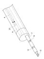
- the manipulator 2 includes an elongated flexible portion 7, a treatment portion 15 such as a grasping forceps disposed at the tip of the flexible portion 7, and a joint 16 that changes the posture of the treatment portion 15. It has.
- a manipulator driving unit 11 that drives the manipulator 2 is provided at the base end of the flexible portion 7, and generates power to drive the manipulator 2 based on a command from a manipulator control unit 3 described later. It is supposed to let you.
- the manipulator drive unit 11 includes a motor (not shown) that generates power, and the treatment unit 15 and the joint 16 are operated via a power transmission member such as a wire by the rotation of the motor.
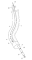
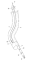
- the shape sensor 4 is, for example, a sensor such as an optical fiber sensor of a long and narrow member having flexibility, and the longitudinal axis of the shape sensor 4 is set at one or more detection points P provided along the longitudinal direction. A signal corresponding to the radius of curvature in the direction along the one plane is included. As shown in FIG. 2, the shape sensor 4 is inserted through a path A provided in parallel along the longitudinal direction of the manipulator channel 13, and is provided at the base end of the shape sensor 4. The shape sensor 4 can be driven forward and backward along the longitudinal direction of the path A by the rotational drive of the shape sensor drive unit 8. More specifically, as shown in FIG.
- the shape sensor 4 made of a long member is folded around a guide member 17 disposed near the distal end of the manipulator 2, and its proximal end portion Is connected to a motor 18 disposed near the proximal end of the manipulator 2.
- the shape sensor 4 is formed in a loop shape between the motor 18 of the shape sensor driving unit 8 and the guide member 17, and is shaped between the motor 18 and the guide member 17 as the motor 18 rotates. The sensor 4 is moved forward and backward by being pulled and extended.
- the position information calculation unit 9 calculates the movement amount (longitudinal position information) in the longitudinal direction of the shape sensor 4 based on the drive amount (insertion amount) of the shape sensor 4 inserted by the shape sensor drive unit 8.
- the amount of movement of the shape sensor 4 in the longitudinal direction can be calculated, for example, by converting the amount of rotation of the motor 18.
- a rotating member such as a roller (not shown) that contacts the outer surface of the shape sensor 4 and is rotated by movement of the shape sensor 4 in the longitudinal direction is disposed, and the shape sensor is based on the amount of rotation of the rotating member.
- Other methods such as calculating the amount of movement in the longitudinal direction of 4 may be adopted.
- the shape estimation unit 6 calculates the shape sensor calculated by the position information calculation unit 9 while moving the shape sensor 4 in the path A provided in parallel along the longitudinal direction of the manipulator channel 13 in which the manipulator 2 is disposed.
- the curved shape of the path A is estimated based on the insertion amount of 4 and a signal corresponding to the radius of curvature detected by the shape sensor 4. Since the path A through which the shape sensor 4 is inserted is provided in parallel along the longitudinal direction of the manipulator channel 13 through which the manipulator 2 is inserted, when the manipulator 2 is inserted into the manipulator channel 13, the manipulator channel The shape of the flexible part 7 of the manipulator 2 changes following the shape of 13, and the shape of the shape sensor 4 inserted through the path A changes. Therefore, the shape information of the path A and the shape information of the manipulator channel 13 are substantially equal, and the curved shape of the path A can be regarded as the curved shape of the manipulator channel 13.
- the path A through which the shape sensor 4 is inserted is arranged so as to run along the channel provided in the manipulator 2 itself or the outer surface of the manipulator 2 in addition to the channel provided in the endoscope or overtube in which the manipulator 2 is inserted.
- the control parameter calculation unit 10 calculates the control parameters of the manipulator 2 from the information on the curved shape of the manipulator 2 estimated by the shape estimation unit 6.
- the manipulator control unit 3 controls the manipulator 2 based on the control parameters of the manipulator 2 calculated by the control parameter calculation unit 10.
- the overtube 5 is inserted to the vicinity of the affected part along the patient's twisted body cavity. Since the overtube 5 is flexible, the overtube 5 is curved following the shape of the body cavity of the patient. Then, the manipulator 2 selected in accordance with the treatment is inserted into the manipulator channel 13 provided in the overtube 5.
- the shape sensor 4 is inserted into the path A provided in the overtube 5. Then, while the shape sensor is driven forward and backward in the longitudinal direction between the motor 18 and the guide member 17 by the motor 18, the measurement of the radius of curvature at each position of one or more detection points P and the length of the shape sensor 4 are performed.
- the curved shape of the manipulator channel 13 is estimated by the shape estimation unit 6 based on the data obtained by repeating the movement in the direction and associating the obtained information on the plurality of curvature radii with the information on the position in the longitudinal direction.
- the curved shape of the manipulator channel 13 can be estimated by tracing with the shape sensor 4.
- the manipulator 2 Since the curved shape of the manipulator channel 13 is estimated in this way, even if the manipulator 2 is inserted into the manipulator channel 13, the manipulator 2 is based on the estimated curved shape of the manipulator channel 13. It is controlled by the manipulator control unit 3 and the operability of the manipulator 2 can be improved.
- the overtube 5 When the overtube 5 is moved to treat a different affected part from the state of treating one affected part, the patient's body position is changed, or the organ is moved, the shape of the body cavity of the patient is changed. In some cases, the overtube 5 is also bent in accordance with the changed shape of the body cavity. In such a case, the curved shape of the manipulator channel 13 is estimated while the shape sensor 4 is advanced and retracted in the longitudinal direction again in the path A, and the manipulator 2 is adjusted according to the estimated curved shape of the manipulator channel 13. What is necessary is just to repeat the operation
- the shape sensor 4 is connected to the path of the overtube 5 even when the affected part is moved in the middle of the hand or the patient's body position is changed.
- the manipulator 2 can be controlled in the manipulator channel 13 while being arranged without being inserted or removed from A.
- a plurality of shape information is detected at each position by one or more detection points P while moving a small number of shape sensors 4 in the longitudinal direction of the path A. Since the curved shape of the manipulator channel 13 is estimated, a large number of shape sensors 4 are unnecessary, and the curved shape along the longitudinal direction of the manipulator 2 can be measured using the minimum shape sensor 4. is there. Further, since the procedure can be performed while the shape sensor 4 is arranged without being inserted or removed from the path A, it is possible to estimate the curved shape along the longitudinal direction of the manipulator 2 when arranged in the manipulator channel 13 in real time. it can.
- the manipulator 2 is controlled based on the control parameters calculated from the estimated curved shape information of the manipulator 2, the attenuation of the driving force of the manipulator 2 and the interference of the joint are compensated, and the shape of the flexible portion 7 is compensated.
- the manipulator 2 can be controlled well.
- the shape estimation unit 6 compares the detected shape information of the manipulator channel 13 with the shape information of the manipulator channel 13 detected in advance, and the difference is equal to or greater than a predetermined threshold value.
- the shape information may be updated.
- the shape information of the manipulator channel 13 detected by the shape sensor 4 and the shape information of the manipulator channel 13 detected before N + 1 cycles (N ⁇ 0) are obtained.
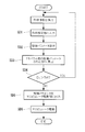
- comparison step SA1
- the difference D R is the case where the first threshold value Th1 or more (step SA2), and updates the configuration information of the manipulator 2 it is determined that the shape of the manipulator for the channel 13 is changed (Step SA3).
- the control parameter calculation unit 10 calculates a control parameter of the manipulator 2 based on the updated shape information (step SA4), and the manipulator control unit 3 controls the manipulator 2 based on the calculated control parameter. Is performed (step SA5). Further, if the difference D R between the shape information and shape information of the manipulator for the channel 13, N + 1 cycle (N ⁇ 0) manipulator channel 13 which is detected before is the first threshold value Th1 or less (step SA2 ), The shape information is transmitted to the control parameter calculation unit 10 as it is, and the control parameters of the manipulator 2 are calculated based on the shape information (step SA4). The manipulator control unit 3 controls the manipulator 2 based on the control parameter calculated by the control parameter calculation unit 10 (step SA5).
- the medical manipulator system 1 according to the present embodiment, there is an advantage that the manipulator 2 can be prevented from being inadvertently operated in the case of an error or a shake, and the manipulator 2 can be controlled with high accuracy. is there.
- the shape sensor drive unit 8 drives the shape sensor 4, the shape estimation unit 6 estimates the curved shape of the manipulator 2, and the control parameter calculation unit 10 calculates the control parameters of the manipulator 2 in real time. .
- the manipulator 2 can be controlled smoothly even if the control parameters change.
- driving of the shape sensor 4 by the shape sensor driving unit 8, estimation of the curved shape of the manipulator 2 by the shape estimation unit 6, and calculation of the control parameters of the manipulator 2 by the control parameter calculation unit 10 are performed by the manipulator 2 by the manipulator control unit 3.
- the controllability of the manipulator 2 can be improved by performing control of the manipulator at a control cycle of 10000 times or less, for example, the control cycle of the manipulator is 100 ⁇ s and the parameters are calculated from the shape estimation at 1 s or less.
- the shape sensor drive unit 8, the shape estimation unit 6, the control parameter calculation unit 10, and the manipulator control unit 3 may be configured to be operable in separate and independent operation modes.
- the parameter calculation mode in which the shape sensor 4 detects the shape information of the manipulator channel 13 without calculating the manipulator 2 and calculates the control parameters of the manipulator 2, and the shape information of the manipulator channel 13 is obtained.
- the control is switched to the manipulator control mode in which the manipulator 2 is controlled and the treatment is performed without performing the detection and calculation of the control parameters. Therefore, in the parameter calculation mode, the manipulator 2 is stopped, so that the manipulator 2 is not driven unnecessarily and can be operated safely.
- the shape estimation unit 6 when the shape information of the manipulator channel 13 detected by the shape sensor 4 is equal to or greater than the second threshold, it is determined that an abnormality has occurred, and the shape estimation unit 6 again determines that the shape sensor 4
- the shape information of the manipulator channel 13 may be detected. Specifically, as shown in FIG. 6, when the shape information R of the manipulator channel 13 detected by the shape sensor 4 is equal to or more than the second threshold Th2, it cannot be used normally.
- the shape estimation unit 6 again causes the shape sensor 4 to detect the shape information of the manipulator channel 13 (step SB1). Further, when the shape information R of the manipulator channel 13 detected by the shape sensor 4 is smaller than the second threshold Th2, it is determined that there is no abnormality such as misalignment, and the detected shape information R is controlled.
- the control parameter calculation unit 10 calculates a control parameter of the manipulator 2 based on the output shape information R (step SB3), and the manipulator control unit 3 controls the manipulator 2 based on the calculated control parameter. (Step SB4).
- the control parameter calculation unit 10 calculates a control parameter of the manipulator 2 based on the output shape information R (step SB3), and the manipulator control unit 3 controls the manipulator 2 based on the calculated control parameter. (Step SB4).
- the manipulator control unit 3 compares the control parameter of the manipulator 2 calculated by the control parameter calculation unit 10 with the control parameter of the manipulator 2 calculated one cycle before, and the difference is When the threshold value is 3 or more, the corrected control parameter corrected by the high-frequency cutoff filter stored in the manipulator control unit 3 may be output to the manipulator driving unit 11.
- the shape information of the manipulator channel 13 detected by the shape sensor 4 is input to the shape estimation unit 6 (step SC1), and the manipulator 2 is controlled based on this shape information.
- the parameter is calculated by the control parameter calculation unit 10 (step SC2).
- the manipulator control unit 3 compares the calculated control parameter with the control parameter of the manipulator 2 calculated one cycle before (step SC3), and when the difference Dk is equal to or greater than the third threshold Th3.
- Step SC4 the corrected control parameter corrected by the high-frequency cutoff filter stored in the manipulator control unit 3 is output to the manipulator driving unit 11 (step SC5).
- the manipulator 2 is driven by the manipulator driving unit 11 (step SC7).
- the control parameter is output as it is to the manipulator driving unit 11 ( Step SC6)
- the manipulator 2 is driven by the manipulator driving unit 11 (step SC7).
- the difference Dk between the control parameter of the manipulator 2 and the control parameter of the manipulator 2 calculated one cycle before is equal to or greater than the third threshold Th3.
- the driving amount of the manipulator 2 can be suppressed within a certain range even if the parameter changes suddenly. It can be driven.
- the manipulator control unit 3 compares the control parameter of the manipulator 2 calculated by the control parameter calculation unit 10 with the control parameter of the manipulator 2 calculated one cycle before, and the difference is If the threshold value Th4 is larger than 4, it may be determined as abnormal, and the shape sensor 4 may detect the shape information of the manipulator channel 13 again.
- the shape information of the manipulator channel 13 detected by the shape sensor 4 is output to the shape estimation unit 6 (step SD1), and the manipulator 2 is controlled based on this shape information.
- the parameter is calculated by the control parameter calculation unit 10 (step SD2).
- the manipulator control unit 3 compares the calculated control parameter with the control parameter of the manipulator 2 calculated one cycle before (step SD3), and when the difference Dk is larger than the fourth threshold Th4. It judges that it is abnormal (step SD4), and makes the shape sensor 4 detect the shape information of the channel 13 for the manipulator again.
- step SD5 When the difference Dk is equal to or smaller than the fourth threshold Th4, the control parameter is output as it is to the manipulator driving unit 11 (step SD5), and the manipulator 2 is operated by the manipulator driving unit 11 based on the output control parameter. Driven (step SD6).
- the difference Dk between the control parameter of the manipulator 2 and the control parameter of the manipulator 2 calculated one cycle before is greater than the fourth threshold Th4. If it is larger, it is determined that there is some abnormality, so that it is possible to prevent the manipulator 2 from being forcibly driven based on the abnormal value, and to perform a treatment safely.
- a warning unit (not shown) may be provided that warns the operator that an abnormal state is detected by voice or the like when a determination of abnormality is detected a predetermined number of times or more. By doing so, when there is some abnormality such as a displacement that cannot be used in normal use, it is handled so that the manipulator 2 is not controlled or driven based on the abnormal value. be able to.
- the joint 16 may be controlled by the manipulator driving unit 11 based on the shape information of the manipulator 2 detected by the shape sensor 4. Since the joint of the manipulator 2 is controlled based on the shape information of the manipulator, there is an advantage that the controllability of the angle of the tip of the manipulator 2 can be improved.
- the shape sensor driving unit 8 includes a motor 18 disposed in the vicinity of the proximal end of the manipulator 2 and a guide member 17 disposed in the vicinity of the distal end of the manipulator 2, and is formed in a loop shape.
- the sensor 4 has been described as being driven forward and backward between the motor 18 and the guide member 17, instead of this, as a first modification, for example, as shown in FIG. 4B, the tip of the shape sensor 4 is used.
- a pulling wire 12 having a diameter smaller than that of the shape sensor 4 may be connected to the loop, and a loop formed by the shape sensor 4 and the pulling wire 12 may be driven forward and backward between the motor 18 and the guide member 17. .
- the shape sensor 4 can be prevented from being broken or damaged, and a pulling wire having a diameter smaller than that of the shape sensor can be prevented.
- the inner diameter of the path A through which the shape sensor 4 is inserted can be reduced.
- the shape sensor 4 is connected to one end of the traction wire 12 and the other end of the traction wire 12 is arranged in parallel with the shape sensor 4.
- the shape sensor 19 may be connected, and the loop formed by the shape sensor 4, the pulling wire 12, and the sub-shape sensor 19 may be driven forward and backward between the motor 18 and the guide member 17.
- a stopper 20 that prevents the shape sensor 4 from entering the guide member 17 may be provided between the shape sensor 4 and the guide member 17. By doing in this way, it can prevent that the shape sensor 4 is wound around the guide member 17, and it can prevent the bending and damage of the shape sensor 4 with a simple structure.
- the stopper 20 exemplifies a cylindrical body whose inner diameter is smaller than the outer diameter of the shape sensor 4, but the tip of the shape sensor 4 can be prevented from entering the guide member 17. Any member may be used as long as it has a shape.
- a pressure receiving member 21 made of, for example, a balloon or the like that can be expanded to the same diameter as the inner diameter of the path A is provided at the tip of the shape sensor 4, and the motor 18 and guide
- pressure feeding means 22 that drives the shape sensor 4 to move forward and backward by applying pressure in the longitudinal direction to the pressure receiving member 21 may be provided.
- the pressure feeding means 22 a pump or the like that applies propulsive force by adding water pressure or air pressure to the pressure receiving member 21 can be used.
- the shape sensor 4 can be easily driven forward and backward in the longitudinal direction by applying pressure from the pressure feeding means to the pressure receiving member 21. . Moreover, since the internal diameter of the path
Abstract
本発明に係る医療用マニピュレータシステム(1)は、マニピュレータ(2)と、マニピュレータ用チャネル(13)と、マニピュレータ用チャネル(13)に沿う経路(A)と、マニピュレータ用チャネル(13)の形状情報を検出する形状センサ(4)と、形状センサ(4)を駆動させる形状センサ駆動部(8)と、マニピュレータ(2)を駆動させるマニピュレータ駆動部(11)と、形状センサ駆動部(8)の駆動量に基づいて形状センサ(4)の位置情報を算出する位置情報算出部(9)と、マニピュレータ用チャネル(13)の形状情報と位置情報とに基づいてマニピュレータ(2)の湾曲形状を推定する形状推定部(6)と、湾曲形状情報からマニピュレータ(2)の制御パラメータを算出する制御パラメータ算出部(10)と、制御パラメータに基づいてマニピュレータ2を制御するマニピュレータ制御部(3)と、を備える。
Description
本発明は、医療用マニピュレータの形状取得方法および制御方法に関するものである。
患者の体腔内に挿入される内視鏡の鉗子チャネル等を経由して患者の体内に医療用マニピュレータを挿入し、患部の処置を行う医療用マニピュレータシステムが知られている(例えば、特許文献1参照。)。
特許文献1の医療用マニピュレータシステムでは、光ファイバセンサにより検出した曲げに関する情報と運動学的なモデルに関する情報とに基づいて、マニピュレータの運動学的な形状情報、すなわち、マニピュレータの関節角度に関する情報を推定している。
特許文献1の医療用マニピュレータシステムでは、光ファイバセンサにより検出した曲げに関する情報と運動学的なモデルに関する情報とに基づいて、マニピュレータの運動学的な形状情報、すなわち、マニピュレータの関節角度に関する情報を推定している。
しかしながら、特許文献1に記載の医療用マニピュレータシステムでは、医療用マニピュレータの長手方向に沿う複数箇所での曲げ半径を検出するために多数の光ファイバを束ねたファイババンドルが必要となる。マニピュレータは、低侵襲化のために細径化が求められるが、多数のファイババンドルを用いるとマニピュレータが太径化して細径化が妨げられ、低侵襲化の実現が困難になる。また、医療用マニピュレータ製造のための部品点数が多くなり、コストがかかるという不都合がある。
本発明は、上述した事情に鑑みてなされたものであって、マニピュレータの細径化を図りながら、最小限のセンサを用いて医療用マニピュレータの長手方向に沿う軟性形状を継続的に推定することができる医療用マニピュレータの形状取得方法および制御方法を提供することを目的としている。
本発明の一態様は、軟性部を有し先端に1以上の関節を有する長尺のマニピュレータと、該マニピュレータを貫通させるマニピュレータ用チャネルと、該マニピュレータ用チャネルの長手方向に沿って設けられる経路と、該経路内部を移動可能に設けられ、前記マニピュレータ用チャネルの形状情報を検出する1以上の検出点を有する形状センサと、前記形状センサを前記経路の長手方向に沿って前進後退駆動させる形状センサ駆動部と、前記マニピュレータを駆動させるマニピュレータ駆動部と、前記マニピュレータおよび前記形状センサを制御する制御部と、を備え、該制御部は、該形状センサ駆動部の駆動量に基づいて前記形状センサの長手方向位置情報を算出する位置情報算出部と、検出された前記マニピュレータ用チャネルの形状情報と、算出された前記形状センサの長手方向位置情報とに基づいて、前記マニピュレータの湾曲形状を推定する形状推定部と、推定された前記マニピュレータの湾曲形状の情報から前記マニピュレータの制御パラメータを算出する制御パラメータ算出部と、算出された前記制御パラメータに基づいて、前記マニピュレータの制御を行うマニピュレータ制御部と、を備える医療用マニピュレータシステムである。
本態様によれば、軟性部を有する長尺のマニピュレータが配置されるマニピュレータ用チャネルの長手方向に沿って設けられる経路に1以上の検出点を有する形状センサを挿通し、形状センサを経路の長手方向に沿って前進後退駆動させながら形状センサによってマニピュレータ用チャネルの形状を検出することにより、検出されたマニピュレータ用チャネルの形状とその長手方向位置情報とに基づいてマニピュレータの湾曲形状を推定することができる。すなわち、手技を行いながら、少ない数の形状センサをリアルタイムで長手方向に前進後退駆動させて長手方向の各位置において形状を検出することができるので、多数の光ファイバを束ねたファイババンドルのような形状センサを用いることなく、最小限のセンサを用いて、マニピュレータ用チャネルの形状、すなわち、該マニピュレータ用チャネルに配置されたときのマニピュレータの長手方向に沿う湾曲形状を推定することができる。
また、形状センサは1以上の検出点を有しているので、最小限の移動操作で複数の経路情報を検出することができる。
さらに、推定されたマニピュレータの湾曲形状の情報から制御パラメータ算出部によりマニピュレータの制御パラメータを算出し、算出された制御パラメータに基づいて、マニピュレータの制御を行うので、マニピュレータの駆動力の減衰や関節の干渉を補償し、軟性部の形状によらずマニピュレータを良好に制御することができる。
さらに、推定されたマニピュレータの湾曲形状の情報から制御パラメータ算出部によりマニピュレータの制御パラメータを算出し、算出された制御パラメータに基づいて、マニピュレータの制御を行うので、マニピュレータの駆動力の減衰や関節の干渉を補償し、軟性部の形状によらずマニピュレータを良好に制御することができる。
上記態様においては、前記形状推定部は、形状センサにより検出された前記マニピュレータ用チャネルの前記形状情報と、N+1サイクル(N≧0)前に検出された同一の前記マニピュレータ用チャネルの形状情報とを比較し、その差分が第1の閾値以上となる場合には前記マニピュレータの形状情報を更新することとしてもよい。
このようにすることで、検出されたマニピュレータ用チャネルの形状情報と事前に検出されたマニピュレータ用チャネルの形状情報とを比較して、その差分が第1の閾値以上となる場合にのみマニピュレータの形状情報を更新することとしたので、誤差やぶれ等の場合にマニピュレータが不用意に操作されることを防ぎ、精度よくマニピュレータを制御することができる。
また、上記態様においては、前記形状センサ駆動部が、前記マニピュレータの基端付近に配置され、回転駆動により該形状センサを前進後退駆動させる動力を発生するモータと、前記マニピュレータの先端付近に配置され、前記形状センサの一部が掛け回されこれにより該形状センサをガイドするガイド部材と、を備え、前記モータの回転駆動に伴い前記形状センサを牽引及び繰出すことにより、前記形状センサを前進後退駆動させることとしてもよい。
このようにすることで、形状センサが、マニピュレータ用チャネルに平行に設けられた経路内において、マニピュレータの基端付近に配置されたモータとマニピュレータの先端付近に配置されたガイド部材との間を前進後退駆動可能となる。したがって、マニピュレータ用チャネルに配置されたマニピュレータ(特に軟性部)の全長にわたってマニピュレータの湾曲形状を推定することができる。また、マニピュレータにより手技を行っている場合であっても、マニピュレータ用チャネルに平行に配置された経路内において形状センサを前進後退駆動させることができるので、手技中にリアルタイムでマニピュレータの湾曲形状を推定することができる。
また、上記態様においては、前記形状センサの先端には該形状センサよりも細径の牽引用ワイヤが接続され、前記形状センサ駆動部が、前記マニピュレータの基端付近に配置され、回転駆動により前記牽引用ワイヤを介して該形状センサを前進後退駆動させる動力を発生するモータと、前記マニピュレータの先端付近に配置され、前記牽引用ワイヤの一部が掛け回されこれにより該引用ワイヤをガイドするガイド部材と、を備え、前記モータの回転駆動に伴い前記形状センサを牽引及び繰出すことにより、前記形状センサを前進
このようにすることで、形状センサが、マニピュレータ用チャネルに平行に設けられた経路内において、マニピュレータの基端付近に配置されたモータとマニピュレータの先端付近に配置されたガイド部材との間を前進後退駆動可能となる。このとき、形状センサの先端には牽引用ワイヤが接続されており、ガイド部材にはこの牽引用ワイヤの一部が掛け回される。したがって、形状センサがガイド部材に掛け回されないため、形状センサの折れや破損を防ぐことができる。また、牽引用ワイヤは形状センサよりも細径であるので、ガイド部材のR部の径を小さくすることができる。したがって、形状センサが挿通される経路の内径を小さくすることができ、医療用マニピュレータシステムの寸法を小さくすることができる。
また、上記態様においては、前記牽引用ワイヤにおける前記形状センサが接続されている側とは反対側の端部には、前記形状センサに並列して配置される副形状センサが接続されることとしてもよい。
このようにすることで、1以上の検出点を有する形状センサと、副形状センサの2本の形状センサにより、経路の長手方向の各位置において、2方向のマニピュレータ用チャネルの形状情報を同時に検出することができ、より精密かつ迅速にマニピュレータの湾曲形状を推定することができる。
このようにすることで、1以上の検出点を有する形状センサと、副形状センサの2本の形状センサにより、経路の長手方向の各位置において、2方向のマニピュレータ用チャネルの形状情報を同時に検出することができ、より精密かつ迅速にマニピュレータの湾曲形状を推定することができる。
また、上記態様においては、前記形状センサと前記ガイド部材との間には、前記形状センサの前記ガイド部材への侵入を防止するストッパを設けることとしてもよい。
このようにすることで、形状センサがガイド部材に掛け回されることを防ぐことができ、形状センサの折れ曲がりや破損を簡易に防ぐことができる。
このようにすることで、形状センサがガイド部材に掛け回されることを防ぐことができ、形状センサの折れ曲がりや破損を簡易に防ぐことができる。
また、上記態様においては、前記形状センサの先端には、前記経路内径と略同径に拡張可能な受圧部材が設けられ、形状センサ駆動部は、前記受圧部材に対して長手方向に圧力を付加することで前記形状センサを前進後退駆動させる送圧手段が設けられていてもよい。
このようにすることで、形状センサが柔軟な素材から形成されている場合であっても、形状センサの先端に設けられた受圧部材に対し、送圧手段により長手方向に圧力を付加することで、形状センサを容易に長手方向に前進後退駆動させることができる。
また、形状センサの一部を掛け回してガイドするガイド部材とモータとにより形状センサを駆動させる構造に比べ、形状センサが挿通される経路の内径を小さくすることができ、したがって、医療用マニピュレータシステムの寸法を小さくすることができる。
このようにすることで、形状センサが柔軟な素材から形成されている場合であっても、形状センサの先端に設けられた受圧部材に対し、送圧手段により長手方向に圧力を付加することで、形状センサを容易に長手方向に前進後退駆動させることができる。
また、形状センサの一部を掛け回してガイドするガイド部材とモータとにより形状センサを駆動させる構造に比べ、形状センサが挿通される経路の内径を小さくすることができ、したがって、医療用マニピュレータシステムの寸法を小さくすることができる。
また、上記態様においては、前記形状推定部が、前記形状センサにより検出された前記マニピュレータ用チャネルの形状情報が第2の閾値以上となる場合に異常と判断し、再度、前記形状センサによる前記マニピュレータ用チャネルの形状情報の検出を行わせることとしてもよい。
このようにすることで、マニピュレータ用チャネルの形状情報が第2の閾値以上となる場合には、通常の使用ではあり得えないほどの位置ずれ等、何らかの異常があると判断して、再度、形状センサにマニピュレータ用チャネルの形状情報を検出させる。したがって、異常な値に基づいてマニピュレータの無理な制御や駆動が行わることを防き、安全性を確保することができる。
このようにすることで、マニピュレータ用チャネルの形状情報が第2の閾値以上となる場合には、通常の使用ではあり得えないほどの位置ずれ等、何らかの異常があると判断して、再度、形状センサにマニピュレータ用チャネルの形状情報を検出させる。したがって、異常な値に基づいてマニピュレータの無理な制御や駆動が行わることを防き、安全性を確保することができる。
また、上記態様においては、前記マニピュレータ制御部が、前記制御パラメータ算出部が算出した前記マニピュレータの制御パラメータと、1サイクル前に算出された前記マニピュレータの制御パラメータとを比較し、その差分が第3の閾値以上となる場合には、前記マニピュレータ制御部に保存された高域遮断フィルタにより補正された補正後制御パラメータを、前記マニピュレータ駆動部に出力するよう制御することとしてもよい。
このようにすることで、マニピュレータの制御パラメータと、1サイクル前に算出されたマニピュレータの制御パラメータとの差分が第3の閾値以上となる場合には、高域遮断フィルタにより補正された補正後制御パラメータに基づいてマニピュレータが駆動されるので、マニピュレータの駆動量を一定範囲内に抑えることができる。したがって、急激にパラメータが変化することによるマニピュレータの動作の不安定化を回避し、マニピュレータを安定して駆動させることができる。
また、上記態様においては、前記マニピュレータ制御部が、前記制御パラメータ算出部が算出した前記マニピュレータの制御パラメータと、1サイクル前に算出された前記マニピュレータの制御パラメータとを比較し、その差分が第4の閾値よりも大きい場合には、異常と判断し、再度、前記形状センサに前記マニピュレータ用チャネルの形状情報の検出を行わせるよう制御することとしてもよい。
このようにすることで、マニピュレータの制御パラメータと、1サイクル前に算出されたマニピュレータの制御パラメータとの差分が第4の閾値よりも大きい場合には、何らかの異常があると判断されるので、異常な値に基づいてマニピュレータが無理に制御されることを防ぐことができ、安全に操作を行うことができる。
また、上記態様においては、前記異常との判断が所定の回数以上検知された場合に異常状態であることを操作者に警告する警告部をさらに備えていてもよい。
このようにすることで、異常が所定回数以上検知された場合には、視覚や聴覚等を介して異常を操作者に確実に認識させることができ、安全性を高めることができる。
このようにすることで、異常が所定回数以上検知された場合には、視覚や聴覚等を介して異常を操作者に確実に認識させることができ、安全性を高めることができる。
また、上記態様においては、前記マニピュレータ駆動部は、前記形状センサにより取得した前記マニピュレータの形状情報に基づいて前記関節の制御を行うこととしてもよい。
このようにすることで、マニピュレータの関節は、マニピュレータの軟性部の形状情報に基づいて制御されるので、マニピュレータの先端部の角度の制御性を向上させることができる。
このようにすることで、マニピュレータの関節は、マニピュレータの軟性部の形状情報に基づいて制御されるので、マニピュレータの先端部の角度の制御性を向上させることができる。
また、本発明の一態様は、軟性部を有し先端に1以上の関節をする長尺のマニピュレータが配置されるマニピュレータ用チャネルの長手方向に沿って、1点以上の検出点を有する形状センサを前進後退させる形状センサ駆動ステップと、前記形状センサの駆動量に基づいて前記形状センサの長手方向位置情報を算出する位置情報算出ステップと、検出された形状センサの形状情報と、算出された前記形状センサの長手方向位置において前記形状センサにより検出された前記マニピュレータ用チャネルの形状情報とに基づいて、前記マニピュレータの湾曲形状を推定する形状推定ステップとを含む医療用マニピュレータの湾曲形状推定方法である。
また、本発明の一態様は、上記の医療用マニピュレータの湾曲形状推定方法により推定された前記マニピュレータの湾曲形状の情報から前記マニピュレータの制御パラメータを算出する制御パラメータ算出ステップと、算出された前記制御パラメータに基づいて、前記マニピュレータの制御を行うマニピュレータ制御ステップと、を含む医療用マニピュレータの制御方法である。
本発明によれば、マニピュレータの細径化を図りながら、最小限のセンサを用いて医療用マニピュレータの長手方向に沿う軟性形状を継続的に推定することができるという効果を奏する。
本発明の一実施形態に係る医療用マニピュレータシステム1およびマニピュレータ2の形状取得方法および制御方法について、図面を参照して以下に説明する。
本実施形態に係る医療用マニピュレータシステム1は、図1から図3に示されるように、可撓性を有する材質からなる細長いチューブであるオーバーチューブ5と、該オーバーチューブ5に設けられたマニピュレータ用チャネル13に挿通され、先端に1以上の関節を有する長尺のマニピュレータ2と、該マニピュレータ2が挿入されるマニピュレータ用チャネル13の長手方向に沿って平行に設けられる経路Aに挿通され、マニピュレータ用チャネル13の曲率半径(形状情報)を検出するための形状センサ4と、該形状センサ4を経路Aの長手方向に沿って前進後退駆動させる形状センサ駆動部8と、マニピュレータ2および形状センサ4を制御する制御部100を備えている。
本実施形態に係る医療用マニピュレータシステム1は、図1から図3に示されるように、可撓性を有する材質からなる細長いチューブであるオーバーチューブ5と、該オーバーチューブ5に設けられたマニピュレータ用チャネル13に挿通され、先端に1以上の関節を有する長尺のマニピュレータ2と、該マニピュレータ2が挿入されるマニピュレータ用チャネル13の長手方向に沿って平行に設けられる経路Aに挿通され、マニピュレータ用チャネル13の曲率半径(形状情報)を検出するための形状センサ4と、該形状センサ4を経路Aの長手方向に沿って前進後退駆動させる形状センサ駆動部8と、マニピュレータ2および形状センサ4を制御する制御部100を備えている。
制御部100は、形状センサ駆動部8の駆動量(挿入量)に基づいて形状センサ4の長手方向位置情報を算出する位置情報算出部9と、検出されたマニピュレータ用チャネル13の形状情報(曲率半径)と、算出された形状センサ4の長手方向位置情報とに基づいて、マニピュレータ2の湾曲形状を推定する形状推定部6と、推定されたマニピュレータ2の湾曲形状の情報からマニピュレータ2の制御パラメータを算出する制御パラメータ算出部10と、算出された制御パラメータに基づいて、マニピュレータ2の制御を行うマニピュレータ制御部3と、を備えている。
形状センサ駆動部8は、マニピュレータ2の基端付近に配置され、回転駆動により形状センサ4を前進後退駆動させる動力を発生するモータ18と、マニピュレータ2の先端付近に配置され、形状センサ4の一部が掛け回され、これにより形状センサ4をガイドするガイド部材17とを備えている(図4A参照)。
形状センサ駆動部8は、マニピュレータ2の基端付近に配置され、回転駆動により形状センサ4を前進後退駆動させる動力を発生するモータ18と、マニピュレータ2の先端付近に配置され、形状センサ4の一部が掛け回され、これにより形状センサ4をガイドするガイド部材17とを備えている(図4A参照)。
マニピュレータ2は、図2に示されるように、細長い軟性部7と、該軟性部7の先端に配置された把持鉗子のような処置部15と、該処置部15の姿勢を変化させる関節16とを備えている。軟性部7の基端には、図1に示されるように、マニピュレータ2を駆動させるマニピュレータ駆動部11が備えられ、後述するマニピュレータ制御部3からの指令に基づいてマニピュレータ2を駆動させる動力を発生させるようになっている。マニピュレータ駆動部11は、動力を発生させる図示しないモータを備え、モータの回転によってワイヤなどの動力伝達部材を介して処置部15および関節16を動作させるようになっている。
形状センサ4は、例えば、可撓性を有する細長い長尺部材の光ファイバセンサ等のセンサであって、長手方向に沿って設けられた1以上の検出点Pにおいて、形状センサ4の長手軸を含む一平面に沿う方向の曲率半径に応じた信号を検出するようになっている。図2に示されるように、形状センサ4は、マニピュレータ用チャネル13の長手方向に沿って平行に設けられている経路Aに挿通されるようになっており、形状センサ4の基端に設けられた形状センサ駆動部8の回転駆動により、経路Aの長手方向に沿って形状センサ4を前進後退駆動できるようになっている。より具体的には、図4Aに示されるように、長尺部材からなる形状センサ4は、マニピュレータ2の先端付近に配置されたガイド部材17に掛け回されて折り返されており、その基端部がマニピュレータ2の基端付近に配置されたモータ18に接続されている。言い換えると、形状センサ4は形状センサ駆動部8のモータ18とガイド部材17との間でループ状に形成されており、モータ18の回転駆動に伴い、モータ18とガイド部材17との間で形状センサ4が牽引及び繰出されることで前進後退するようになっている。
位置情報算出部9は、形状センサ駆動部8により挿入された形状センサ4の駆動量(挿入量)に基づいて形状センサ4の長手方向の移動量(長手方向位置情報)を算出する。形状センサ4の長手方向の移動量は、例えば、モータ18の回転量を換算することで算出することができる。また、これに代えて、形状センサ4の外面に接触し、形状センサ4の長手方向の移動によって回転させられる図示しないローラ等の回転部材を配置し、この回転部材の回転量に基づいて形状センサ4の長手方向の移動量を算出する等、その他の方法を採ることとしてもよい。
形状推定部6は、マニピュレータ2の配置されるマニピュレータ用チャネル13の長手方向に沿って並列して設けられる経路A内において形状センサ4を移動させながら、位置情報算出部9により算出された形状センサ4の挿入量と、形状センサ4によって検出された曲率半径に応じた信号とに基づいて経路Aの湾曲形状を推定するようになっている。形状センサ4が挿通される経路Aは、マニピュレータ2が挿通されるマニピュレータ用チャネル13の長手方向に沿って平行に設けられているので、マニピュレータ用チャネル13内にマニピュレータ2を挿入すると、マニピュレータ用チャネル13の形状に倣ってマニピュレータ2の軟性部7の形状が変化し、経路Aに挿通される形状センサ4の形状が変化する。したがって、経路Aの形状情報とマニピュレータ用チャネル13の形状情報はほぼ等しく、経路Aの湾曲形状をマニピュレータ用チャネル13の湾曲形状とみなすことができる。
形状センサ4を挿通させる経路Aは、マニピュレータ2を挿入する内視鏡やオーバーチューブに設けられたチャネルの他、マニピュレータ2自体に設けられたチャネル、或いは、マニピュレータ2の外面に併走するように配置されたチューブの内孔等であり、特に、患者の曲がりくねった体腔内にマニピュレータ2を挿入して体内の患部を処置する場合に、体腔内に挿入された状態のマニピュレータ2の湾曲形状を表す任意の経路としてもよい。
制御パラメータ算出部10は、形状推定部6により推定されたマニピュレータ2の湾曲形状の情報からマニピュレータ2の制御パラメータを算出するようになっている。マニピュレータ制御部3は、制御パラメータ算出部10により算出されたマニピュレータ2の制御パラメータに基づいてマニピュレータ2を制御する。
このように構成された本実施形態に係る医療用マニピュレータシステム1の作用について以下に説明する。
本実施形態に係る医療用マニピュレータシステム1を用いて患者の体腔内の患部を処置するには、まず、患者の曲がりくねった体腔に沿って患部近傍までオーバーチューブ5を挿入する。オーバーチューブ5は可撓性を有するので、患者の体腔の形状に倣って湾曲する。そして、オーバーチューブ5に設けられたマニピュレータ用チャネル13に、処置に応じて選択したマニピュレータ2を挿入する。
本実施形態に係る医療用マニピュレータシステム1を用いて患者の体腔内の患部を処置するには、まず、患者の曲がりくねった体腔に沿って患部近傍までオーバーチューブ5を挿入する。オーバーチューブ5は可撓性を有するので、患者の体腔の形状に倣って湾曲する。そして、オーバーチューブ5に設けられたマニピュレータ用チャネル13に、処置に応じて選択したマニピュレータ2を挿入する。
次に、形状センサ4を、オーバーチューブ5に設けられた経路Aに挿入する。そして、モータ18により、該モータ18とガイド部材17との間で形状センサを長手方向に前進後退駆動させながら、1以上の検出点Pの各位置における曲率半径の測定と、形状センサ4の長手方向への移動とを繰り返し、得られた複数の曲率半径の情報と長手方向位置の情報とを対応づけたデータに基づいて、形状推定部6によりマニピュレータ用チャネル13の湾曲形状が推定される。これにより、マニピュレータ用チャネル13の湾曲形状を形状センサ4によってトレースするようにして推定することができる。
このようにしてマニピュレータ用チャネル13の湾曲形状が推定されるので、マニピュレータ用チャネル13にマニピュレータ2が挿入された状態であっても、マニピュレータ用チャネル13について推定された湾曲形状に基づいてマニピュレータ2がマニピュレータ制御部3により制御され、マニピュレータ2の操作性を向上させることができる。
一の患部を処置している状態から異なる患部を処置するためにオーバーチューブ5を移動させたり、患者の体位が変更されたり、或いは、臓器が動く等した場合には、患者の体腔の形状が変更され、変更された体腔の形状に倣ってオーバーチューブ5も湾曲させられる場合がある。このような場合には、再び経路A内に形状センサ4を長手方向に前進後退させながらマニピュレータ用チャネル13の湾曲形状を推定し、推定されたマニピュレータ用チャネル13の湾曲形状に合わせてマニピュレータ2を湾曲させる動作を繰り返せばよい。
このように、本実施形態に係る医療用マニピュレータシステム1では、手義の最中に患部を移動させたり患者の体位等が変更された場合であっても、形状センサ4をオーバーチューブ5の経路Aから抜き差しすることなく配置したままで、マニピュレータ用チャネル13内においてマニピュレータ2を制御することができる。
このように、本実施形態に係る医療用マニピュレータシステム1では、手義の最中に患部を移動させたり患者の体位等が変更された場合であっても、形状センサ4をオーバーチューブ5の経路Aから抜き差しすることなく配置したままで、マニピュレータ用チャネル13内においてマニピュレータ2を制御することができる。
また、本実施形態に係る医療用マニピュレータシステム1によれば、少ない数の形状センサ4を経路Aの長手方向に移動させながら、1以上の検出点Pにより各位置で複数の形状情報を検出してマニピュレータ用チャネル13の湾曲形状を推定するので、多数の形状センサ4が不要であり、最小限の形状センサ4を用いてマニピュレータ2の長手方向に沿う湾曲形状を測定することができるという利点がある。
さらに、形状センサ4を経路Aから抜き差しすることなく配置したまま手技を行うことができるので、リアルタイムでマニピュレータ用チャネル13に配置されたときのマニピュレータ2の長手方向に沿う湾曲形状を推定することができる。
さらにまた、推定されたマニピュレータ2の湾曲形状の情報から算出された制御パラメータに基づいてマニピュレータ2の制御を行うので、マニピュレータ2の駆動力の減衰や関節の干渉を補償し、軟性部7の形状によらずマニピュレータ2を良好に制御することができるという利点もある。
さらに、形状センサ4を経路Aから抜き差しすることなく配置したまま手技を行うことができるので、リアルタイムでマニピュレータ用チャネル13に配置されたときのマニピュレータ2の長手方向に沿う湾曲形状を推定することができる。
さらにまた、推定されたマニピュレータ2の湾曲形状の情報から算出された制御パラメータに基づいてマニピュレータ2の制御を行うので、マニピュレータ2の駆動力の減衰や関節の干渉を補償し、軟性部7の形状によらずマニピュレータ2を良好に制御することができるという利点もある。
なお、本実施形態においては、形状推定部6は、検出されたマニピュレータ用チャネル13の形状情報と、事前に検出されたマニピュレータ用チャネル13の形状情報とを比較し、その差分が所定の閾値以上となる場合には形状情報を更新することとしてもよい。
具体的には、図5に示されるように、形状センサ4により検出されたマニピュレータ用チャネル13の形状情報と、N+1サイクル(N≧0)前に検出されたマニピュレータ用チャネル13の形状情報とを比較し(ステップSA1)、この差分DRが第1の閾値Th1以上となる場合(ステップSA2)には、マニピュレータ用チャネル13の形状が変化したものと判断してマニピュレータ2の形状情報を更新する(ステップSA3)。そして、制御パラメータ算出部10は、更新された形状情報に基づいてマニピュレータ2の制御パラメータを算出し(ステップSA4)、マニピュレータ制御部3は、この算出された制御パラメータに基づいて、マニピュレータ2の制御を行う(ステップSA5)。
また、マニピュレータ用チャネル13の形状情報と、N+1サイクル(N≧0)前に検出されたマニピュレータ用チャネル13の形状情報との差分DRが第1の閾値Th1以下となる場合には(ステップSA2)、形状情報がそのまま制御パラメータ算出部10に送信され、この形状情報に基づいてマニピュレータ2の制御パラメータが算出される(ステップSA4)。マニピュレータ制御部3は、制御パラメータ算出部10により算出された制御パラメータに基づいて、マニピュレータ2の制御を行う(ステップSA5)。
このように、本実施形態に係る医療用マニピュレータシステム1によれば、誤差やぶれ等の場合にマニピュレータ2が不用意に操作されることを防ぎ、精度よくマニピュレータ2を制御することができるという利点がある。
また、形状センサ駆動部8による形状センサ4の駆動、形状推定部6によるマニピュレータ2の湾曲形状の推定および、制御パラメータ算出部10によるマニピュレータ2の制御パラメータの算出は、リアルタイムで行うこととしてもよい。
このように、リアルタイムでマニピュレータ2の形状を推定して、マニピュレータ2の制御パラメータを継続的に算出・更新することで、制御パラメータが変化したとしても、マニピュレータ2の制御をスムーズに行うことができる。
例えば、形状センサ駆動部8による形状センサ4の駆動、形状推定部6によるマニピュレータ2の湾曲形状の推定および、制御パラメータ算出部10によるマニピュレータ2の制御パラメータの算出を、マニピュレータ制御部3によるマニピュレータ2の制御周期の10000倍以下、例えば、マニピュレータの制御周期が100μs、形状推定からパラメータ算出を1s以下の制御周期で行うことにより、マニピュレータ2の制御性を向上させることができる。
また、形状センサ駆動部8、形状推定部6、制御パラメータ算出部10および、マニピュレータ制御部3を、それぞれ別個独立した動作モードで動作可能に構成することとしてもよい。
このすることで、例えば、マニピュレータ2の制御をおこなわず、形状センサ4によりマニピュレータ用チャネル13の形状情報を検出してマニピュレータ2の制御パラメータを算出するパラメータ算出モードと、マニピュレータ用チャネル13の形状情報の検出および制御パラメータの算出を行わず、マニピュレータ2を制御して処置を行うマニピュレータ制御モードとに切り替えられるようになっている。したがって、パラメータ算出モードでは、マニピュレータ2は停止状態となるので、マニピュレータ2が不要に駆動されることが無く、安全に操作することができる。
このすることで、例えば、マニピュレータ2の制御をおこなわず、形状センサ4によりマニピュレータ用チャネル13の形状情報を検出してマニピュレータ2の制御パラメータを算出するパラメータ算出モードと、マニピュレータ用チャネル13の形状情報の検出および制御パラメータの算出を行わず、マニピュレータ2を制御して処置を行うマニピュレータ制御モードとに切り替えられるようになっている。したがって、パラメータ算出モードでは、マニピュレータ2は停止状態となるので、マニピュレータ2が不要に駆動されることが無く、安全に操作することができる。
また、本実施形態においては、形状センサ4により検出されたマニピュレータ用チャネル13の形状情報が第2の閾値以上となる場合には異常と判断し、形状推定部6が、再度、形状センサ4にマニピュレータ用チャネル13の形状情報の検出を行わせることとしてもよい。具体的には、図6に示されるように、形状センサ4により検出されたマニピュレータ用チャネル13の形状情報Rが第2の閾値Th2以上となる場合には、通常の使用ではあり得えないほどの位置ずれ等、何らかの異常があると判断し、再度、形状推定部6が、形状センサ4にマニピュレータ用チャネル13の形状情報を検出させる(ステップSB1)。
また、形状センサ4により検出されたマニピュレータ用チャネル13の形状情報Rが第2の閾値Th2よりも小さい場合には、位置ずれ等の異常がないものと判断し、検出された形状情報Rを制御パラメータ算出部に出力する(ステップSB2)。制御パラメータ算出部10は、出力された形状情報Rに基づいてマニピュレータ2の制御パラメータを算出し(ステップSB3)、この算出された制御パラメータに基づいて、マニピュレータ制御部3はマニピュレータ2の制御を行う(ステップSB4)。
このように、本実施形態に係る医療用マニピュレータシステム1によれば、異常な値に基づいてマニピュレータ2の無理な制御や駆動が行わることを防ぎ、安全性を確保することができる。
また、本実施形態においては、マニピュレータ制御部3が、制御パラメータ算出部10が算出したマニピュレータ2の制御パラメータと、1サイクル前に算出されたマニピュレータ2の制御パラメータとを比較し、その差分が第3の閾値以上となる場合には、マニピュレータ制御部3に保存された高域遮断フィルタにより補正された補正後制御パラメータをマニピュレータ駆動部11に出力することとしてもよい。
具体的には、図7に示されるように、形状センサ4により検出されたマニピュレータ用チャネル13の形状情報が形状推定部6に入力され(ステップSC1)、この形状情報に基づいてマニピュレータ2の制御パラメータが制御パラメータ算出部10により算出される(ステップSC2)。次いで、マニピュレータ制御部3が、算出された制御パラメータを1サイクル前に算出されたマニピュレータ2の制御パラメータと比較し(ステップSC3)、その差分Dkが第3の閾値Th3以上となる場合には(ステップSC4)、マニピュレータ制御部3に保存された高域遮断フィルタにより補正された補正後制御パラメータをマニピュレータ駆動部11に出力する(ステップSC5)。そして、この補正された補正後制御パラメータに基づいて、マニピュレータ駆動部11によりマニピュレータ2が駆動される(ステップSC7)。
また、算出された制御パラメータと1サイクル前に算出されたマニピュレータ2の制御パラメータとの差分Dkが第3の閾値Th3よりも小さい場合には、制御パラメータがそのままマニピュレータ駆動部11に出力され(ステップSC6)、出力された制御パラメータに基づいて、マニピュレータ2がマニピュレータ駆動部11により駆動される(ステップSC7)。
このように、本実施形態に係る医療用マニピュレータシステム1によれば、マニピュレータ2の制御パラメータと、1サイクル前に算出されたマニピュレータ2の制御パラメータとの差分Dkが第3の閾値Th3以上となる場合には補正後制御パラメータに基づいてマニピュレータ2が駆動されるので、急激にパラメータが変化してもマニピュレータ2の駆動量を一定範囲内に抑えることができ、したがって、マニピュレータ2を安定して駆動させることができる。
このように、本実施形態に係る医療用マニピュレータシステム1によれば、マニピュレータ2の制御パラメータと、1サイクル前に算出されたマニピュレータ2の制御パラメータとの差分Dkが第3の閾値Th3以上となる場合には補正後制御パラメータに基づいてマニピュレータ2が駆動されるので、急激にパラメータが変化してもマニピュレータ2の駆動量を一定範囲内に抑えることができ、したがって、マニピュレータ2を安定して駆動させることができる。
また、本実施形態においては、マニピュレータ制御部3が、制御パラメータ算出部10が算出したマニピュレータ2の制御パラメータと、1サイクル前に算出されたマニピュレータ2の制御パラメータとを比較し、その差分が第4の閾値Th4よりも大きい場合には、異常と判断し、再度、形状センサ4にマニピュレータ用チャネル13の形状情報の検出を行わせることとしてもよい。
具体的には、図8に示されるように、形状センサ4により検出されたマニピュレータ用チャネル13の形状情報が形状推定部6に出力され(ステップSD1)、この形状情報に基づいてマニピュレータ2の制御パラメータが制御パラメータ算出部10により算出される(ステップSD2)。次いで、マニピュレータ制御部3が、算出された制御パラメータを1サイクル前に算出されたマニピュレータ2の制御パラメータと比較し(ステップSD3)、その差分Dkが第4の閾値Th4よりも大きい場合には異常と判断し(ステップSD4)、再度、形状センサ4にマニピュレータ用チャネル13の形状情報の検出を行わせる。
また、差分Dkが第4の閾値Th4以下の場合には、制御パラメータがそのままマニピュレータ駆動部11に出力され(ステップSD5)、出力された制御パラメータに基づいて、マニピュレータ2がマニピュレータ駆動部11により駆動される(ステップSD6)。
また、差分Dkが第4の閾値Th4以下の場合には、制御パラメータがそのままマニピュレータ駆動部11に出力され(ステップSD5)、出力された制御パラメータに基づいて、マニピュレータ2がマニピュレータ駆動部11により駆動される(ステップSD6)。
このように、本実施形態に係る医療用マニピュレータシステム1によれば、マニピュレータ2の制御パラメータと、1サイクル前に算出されたマニピュレータ2の制御パラメータとの差分Dkが第4の閾値Th4よりも大きい場合には、何らかの異常があると判断されるので、異常な値に基づいてマニピュレータ2が無理に駆動されることを防ぎ、安全に処置を行うことができる。
なお、本実施形態においては、異常との判断が所定の回数以上検知された場合に、音声等により異常状態であることを操作者に警告する警告部(図示略)を備えることとしてもよい。
このようにすることで、通常の使用ではあり得えないほどの位置ずれ等、何らかの異常がある場合には、異常な値に基づいてマニピュレータ2の無理な制御や駆動が行われないよう対応することができる。
このようにすることで、通常の使用ではあり得えないほどの位置ずれ等、何らかの異常がある場合には、異常な値に基づいてマニピュレータ2の無理な制御や駆動が行われないよう対応することができる。
また、本実施形態においては、形状センサ4により検出されたマニピュレータ2の形状情報に基づいて、マニピュレータ駆動部11により関節16の制御が行われることとしてもよい。
マニピュレータ2の関節がマニピュレータの形状情報に基づいて制御されるので、マニピュレータ2の先端部の角度の制御性を向上させることができるという利点がある。
マニピュレータ2の関節がマニピュレータの形状情報に基づいて制御されるので、マニピュレータ2の先端部の角度の制御性を向上させることができるという利点がある。
本実施形態においては、形状センサ駆動部8が、マニピュレータ2の基端付近に配置されたモータ18と、マニピュレータ2の先端付近に配置されたガイド部材17とを備え、ループ状に形成された形状センサ4をモータ18とガイド部材17との間で前進後退駆動させるもの例示して説明したが、これに代えて、第1変形例として、例えば、図4Bに示すように、形状センサ4の先端に該形状センサ4よりも細径の牽引用ワイヤ12を接続し、形状センサ4と牽引用ワイヤ12により形成されたループをモータ18とガイド部材17との間で前進後退駆動させることとしてもよい。このようにすることで、ガイド部材17には牽引用ワイヤ12を掛け回すこととすれば、形状センサ4の折れや破損を防ぐことができ、また、形状センサよりも細径の牽引用ワイヤを採用することで、形状センサ4が挿通される経路Aの内径を小さくすることができる。
また、第2変形例として、図4Cに示されるように、牽引用ワイヤ12の一端に形状センサ4を接続するとともに牽引用ワイヤ12の他端に、形状センサ4に並列して配置される副形状センサ19を接続し、形状センサ4、牽引用ワイヤ12および、副形状センサ19により形成されたループをモータ18とガイド部材17との間で前進後退駆動させることとしてもよい。このようにすることで、2本の形状センサにより2方向のマニピュレータ用チャネル13の形状情報を同時に検出することができるので、より精密かつ迅速にマニピュレータ2の湾曲形状を推定することができる。
また、第3変形例として、図4Dに示されるように、形状センサ4とガイド部材17との間に、形状センサ4のガイド部材17への侵入を防止するストッパ20を設けることとしてもよい。このようにすることで、形状センサ4がガイド部材17に掛け回されることを防ぎ、形状センサ4の折れ曲がりや破損を簡易な構成で防ぐことができる。
なお、図4Dにおいて、ストッパ20は、その内径が形状センサ4の外径よりも小さい筒状体を例示しているが、形状センサ4の先端がガイド部材17に侵入することを防ぐことができる形状であれば、どのような部材を用いても構わない。
なお、図4Dにおいて、ストッパ20は、その内径が形状センサ4の外径よりも小さい筒状体を例示しているが、形状センサ4の先端がガイド部材17に侵入することを防ぐことができる形状であれば、どのような部材を用いても構わない。
また、第4変形例として、図4Eに示されるように、形状センサ4の先端に、経路A内径と略同径に拡張可能な、例えばバルーン等からなる受圧部材21を設け、モータ18とガイド部材17から成る形状センサ駆動部8の代わりに、受圧部材21に対して長手方向に圧力を付加することで形状センサ4を前進後退駆動させる送圧手段22を設けることとしてもよい。送圧手段22は、受圧部材21に対して水圧や空気圧などを付加して推進力を与えるポンプ等を用いることができる。
形状センサ4が柔軟な素材等から形成されている場合であっても、送圧手段からの圧力が受圧部材21に与えられることにより形状センサ4を容易に長手方向に前進後退駆動させることができる。また、形状センサ駆動部8がガイド部材17とモータ18とから構成されるものに比べ、経路Aの内径を小さくすることができるので、医療用マニピュレータシステム1を細径化することができる。
形状センサ4が柔軟な素材等から形成されている場合であっても、送圧手段からの圧力が受圧部材21に与えられることにより形状センサ4を容易に長手方向に前進後退駆動させることができる。また、形状センサ駆動部8がガイド部材17とモータ18とから構成されるものに比べ、経路Aの内径を小さくすることができるので、医療用マニピュレータシステム1を細径化することができる。
1 医療用マニピュレータシステム
2 マニピュレータ
3 制御部(マニピュレータ制御部)
4 形状センサ
5 オーバーチューブ
6 形状推定部
7 軟性部
8 形状センサ駆動部
9 位置情報算出部
10 制御パラメータ算出部
11 マニピュレータ駆動部
12 牽引用ワイヤ
13 マニピュレータ用チャネル
14 内視鏡用チャネル
15 処置部
16 関節
17 ガイド部材(形状センサ駆動部)
18 モータ(形状センサ駆動部)
19 副形状センサ
20 ストッパ
21 受圧部材
22 送圧手段
100 制御部
A 経路
P 検出点
2 マニピュレータ
3 制御部(マニピュレータ制御部)
4 形状センサ
5 オーバーチューブ
6 形状推定部
7 軟性部
8 形状センサ駆動部
9 位置情報算出部
10 制御パラメータ算出部
11 マニピュレータ駆動部
12 牽引用ワイヤ
13 マニピュレータ用チャネル
14 内視鏡用チャネル
15 処置部
16 関節
17 ガイド部材(形状センサ駆動部)
18 モータ(形状センサ駆動部)
19 副形状センサ
20 ストッパ
21 受圧部材
22 送圧手段
100 制御部
A 経路
P 検出点
Claims (14)
- 軟性部を有し先端に1以上の関節を有する長尺のマニピュレータと、
該マニピュレータを貫通させるマニピュレータ用チャネルと、
該マニピュレータ用チャネルの長手方向に沿って設けられる経路と、
該経路内部を移動可能に設けられ、前記マニピュレータ用チャネルの形状情報を検出する1以上の検出点を有する形状センサと、
前記形状センサを前記経路の長手方向に沿って前進後退駆動させる形状センサ駆動部と、
前記マニピュレータを駆動させるマニピュレータ駆動部と、
前記マニピュレータおよび前記形状センサを制御する制御部と、を備え、
該制御部は、
前記形状センサ駆動部の駆動量に基づいて前記形状センサの長手方向位置情報を算出する位置情報算出部と、
検出された前記マニピュレータ用チャネルの形状情報と、算出された前記形状センサの長手方向位置情報とに基づいて、前記マニピュレータの湾曲形状を推定する形状推定部と、
推定された前記マニピュレータの湾曲形状の情報から前記マニピュレータの制御パラメータを算出する制御パラメータ算出部と、
算出された前記制御パラメータに基づいて、前記マニピュレータの制御を行うマニピュレータ制御部と、を備える医療用マニピュレータシステム。 - 前記形状推定部は、
前記形状センサにより検出された前記マニピュレータ用チャネルの形状情報と、N+1サイクル(N≧0)前に検出された同一の前記マニピュレータ用チャネルの形状情報とを比較し、その差分が第1の閾値以上となる場合には前記マニピュレータの形状情報を更新する請求項1に記載の医療用マニピュレータシステム。 - 前記形状センサ駆動部が、
前記マニピュレータの基端付近に配置され、回転駆動により前記形状センサを前進後退駆動させる動力を発生するモータと、
前記マニピュレータの先端付近に配置され、前記形状センサの一部が掛け回されこれにより該形状センサをガイドするガイド部材と、を備え、
前記モータの回転駆動に伴い前記形状センサを牽引及び繰出すことにより、前記形状センサを前進後退させる請求項1または2に記載の医療用マニピュレータシステム。 - 前記形状センサの先端には該形状センサよりも細径の牽引用ワイヤが接続され、
前記形状センサ駆動部が、
前記マニピュレータの基端付近に配置され、回転駆動により前記牽引用ワイヤを介して該形状センサを前進後退駆動させる動力を発生するモータと、
前記マニピュレータの先端付近に配置され、前記牽引用ワイヤの一部が掛け回されこれにより該引用ワイヤをガイドするガイド部材と、を備え、
前記モータの回転駆動に伴い前記形状センサを牽引及び繰出すことにより、前記形状センサを前進後退させる請求項1または2に記載の医療用マニピュレータシステム。 - 前記牽引用ワイヤにおける前記形状センサが接続されている側とは反対側の端部には、前記形状センサに並列して配置される副形状センサが接続されている請求項4に記載の医療用マニピュレータシステム。
- 前記形状センサと前記ガイド部材との間には、前記形状センサの前記ガイド部材への侵入を防止するストッパが設けられている請求項4または5に記載の医療用マニピュレータシステム。
- 前記形状センサの先端には、前記経路内径と略同径に拡張可能な受圧部材が設けられ、
前記形状センサ駆動部には、前記受圧部材に対して長手方向に圧力を付加することで前記形状センサを前進後退駆動させる送圧手段が設けられている請求項1または2に記載の医療用マニピュレータシステム。 - 前記形状推定部は、
前記形状センサにより検出された前記マニピュレータ用チャネルの形状情報が第2の閾値以上となる場合に異常と判断し、再度、前記形状センサに前記マニピュレータ用チャネルの形状情報の検出を行わせる請求項1から7のいずれかに記載の医療用マニピュレータシステム。 - 前記マニピュレータ制御部は、
前記制御パラメータ算出部が算出した前記マニピュレータの制御パラメータと、1サイクル前に算出された前記マニピュレータの制御パラメータとを比較し、その差分が第3の閾値以上となる場合に、前記マニピュレータ制御部に保存された高域遮断フィルタにより補正された補正後制御パラメータを、前記マニピュレータ駆動部に出力するよう制御する請求項1から8のいずれかに記載の医療用マニピュレータシステム。 - 前記マニピュレータ制御部は、
前記制御パラメータ算出部が算出した前記マニピュレータの制御パラメータと、1サイクル前に算出された前記マニピュレータの制御パラメータとを比較し、その差分が第4の閾値よりも大きい場合には、異常と判断し、再度、前記形状センサに前記マニピュレータ用チャネルの形状情報の検出を行わせるよう制御する請求項1から8のいずれかに記載の医療用マニピュレータシステム。 - 前記異常との判断が所定の回数以上検知された場合に、異常状態であることを操作者に警告する警告部をさらに備える請求項8または10に記載の医療用マニピュレータシステム。
- 前記マニピュレータ駆動部は、前記形状センサにより取得した前記マニピュレータの形状情報に基づいて前記関節の制御を行う請求項1から11のいずれかに記載の医療用マニピュレータシステム。
- 軟性部を有し先端に1以上の関節をする長尺のマニピュレータが配置されるマニピュレータ用チャネルの長手方向に沿って、1点以上の検出点を有する形状センサを前進後退させる形状センサ駆動ステップと、
前記形状センサの駆動量に基づいて前記形状センサの長手方向位置情報を算出する位置情報算出ステップと、
検出された前記形状センサの形状情報と、算出された前記形状センサの長手方向位置において前記形状センサにより検出された前記マニピュレータ用チャネルの形状情報とに基づいて、前記マニピュレータの湾曲形状を推定する形状推定ステップと、を含む医療用マニピュレータの湾曲形状推定方法。 - 請求項13に記載の医療用マニピュレータの湾曲形状推定方法により推定された前記マニピュレータの湾曲形状の情報から前記マニピュレータの制御パラメータを算出する制御パラメータ算出ステップと、
算出された前記制御パラメータに基づいて、前記マニピュレータの制御を行うマニピュレータ制御ステップと、を含む医療用マニピュレータの制御方法。
Priority Applications (2)
| Application Number | Priority Date | Filing Date | Title |
|---|---|---|---|
| PCT/JP2016/088841 WO2018122946A1 (ja) | 2016-12-27 | 2016-12-27 | 医療用マニピュレータの形状取得方法および制御方法 |
| US16/424,935 US11478306B2 (en) | 2016-12-27 | 2019-05-29 | Shape acquiring method and controlling method for medical manipulator |
Applications Claiming Priority (1)
| Application Number | Priority Date | Filing Date | Title |
|---|---|---|---|
| PCT/JP2016/088841 WO2018122946A1 (ja) | 2016-12-27 | 2016-12-27 | 医療用マニピュレータの形状取得方法および制御方法 |
Related Child Applications (1)
| Application Number | Title | Priority Date | Filing Date |
|---|---|---|---|
| US16/424,935 Continuation US11478306B2 (en) | 2016-12-27 | 2019-05-29 | Shape acquiring method and controlling method for medical manipulator |
Publications (1)
| Publication Number | Publication Date |
|---|---|
| WO2018122946A1 true WO2018122946A1 (ja) | 2018-07-05 |
Family
ID=62707097
Family Applications (1)
| Application Number | Title | Priority Date | Filing Date |
|---|---|---|---|
| PCT/JP2016/088841 WO2018122946A1 (ja) | 2016-12-27 | 2016-12-27 | 医療用マニピュレータの形状取得方法および制御方法 |
Country Status (2)
| Country | Link |
|---|---|
| US (1) | US11478306B2 (ja) |
| WO (1) | WO2018122946A1 (ja) |
Families Citing this family (6)
| Publication number | Priority date | Publication date | Assignee | Title |
|---|---|---|---|---|
| US10603124B2 (en) * | 2016-11-08 | 2020-03-31 | The Board Of Trustees Of The Leland Stanford Junior University | Method for navigating a robotic surgical catheter |
| WO2018122946A1 (ja) * | 2016-12-27 | 2018-07-05 | オリンパス株式会社 | 医療用マニピュレータの形状取得方法および制御方法 |
| WO2020028216A1 (en) * | 2018-08-01 | 2020-02-06 | Intuitive Surgical Operations, Inc. | Systems and methods for controlling a robotic manipulator or associated tool |
| EP4167892A1 (en) | 2020-06-19 | 2023-04-26 | Remedy Robotics, Inc. | Systems and methods for guidance of intraluminal devices within the vasculature |
| AU2022305235A1 (en) | 2021-07-01 | 2024-01-18 | Remedy Robotics, Inc. | Vision-based position and orientation determination for endovascular tools |
| US11707332B2 (en) | 2021-07-01 | 2023-07-25 | Remedy Robotics, Inc. | Image space control for endovascular tools |
Citations (6)
| Publication number | Priority date | Publication date | Assignee | Title |
|---|---|---|---|---|
| US20100030063A1 (en) * | 2008-07-31 | 2010-02-04 | Medtronic, Inc. | System and method for tracking an instrument |
| JP2011062291A (ja) * | 2009-09-16 | 2011-03-31 | Hoya Corp | 形状検出装置 |
| JP2012115521A (ja) * | 2010-12-01 | 2012-06-21 | Olympus Medical Systems Corp | 管状挿入システム |
| JP2013519432A (ja) * | 2010-02-12 | 2013-05-30 | インテュイティブ サージカル オペレーションズ, インコーポレイテッド | 捻転に対する感度の低い形状センサを用いた絶対的3次元測定のための方法およびシステム |
| JP2014083289A (ja) * | 2012-10-25 | 2014-05-12 | Olympus Corp | 挿入システム、挿入支援装置、挿入支援方法及びプログラム |
| JP2016523592A (ja) * | 2013-05-16 | 2016-08-12 | インテュイティブ サージカル オペレーションズ, インコーポレイテッド | ロボット医療システムを外部撮像と統合するシステム及び方法 |
Family Cites Families (65)
| Publication number | Priority date | Publication date | Assignee | Title |
|---|---|---|---|---|
| DE3016104A1 (de) * | 1980-04-25 | 1981-10-29 | Siemens AG, 1000 Berlin und 8000 München | Sensorvorrichtung mit einer als empfindliches element dienenden lichtleitfaser |
| JP2793882B2 (ja) | 1990-04-13 | 1998-09-03 | オリンパス光学工業株式会社 | 内視鏡挿入状態検出装置 |
| US6963792B1 (en) * | 1992-01-21 | 2005-11-08 | Sri International | Surgical method |
| US6059718A (en) | 1993-10-18 | 2000-05-09 | Olympus Optical Co., Ltd. | Endoscope form detecting apparatus in which coil is fixedly mounted by insulating member so that form is not deformed within endoscope |
| US5840024A (en) | 1993-10-18 | 1998-11-24 | Olympus Optical Co., Ltd. | Endoscope form detecting apparatus in which coil is fixedly mounted by insulating member so that form is not deformed within endoscope |
| JPH08107875A (ja) | 1994-08-18 | 1996-04-30 | Olympus Optical Co Ltd | 内視鏡形状検出装置 |
| JP4159396B2 (ja) | 1994-08-18 | 2008-10-01 | オリンパス株式会社 | 内視鏡形状検出装置 |
| US5563967A (en) * | 1995-06-07 | 1996-10-08 | Mcdonnell Douglas Corporation | Fiber optic sensor having a multicore optical fiber and an associated sensing method |
| US5798521A (en) * | 1996-02-27 | 1998-08-25 | The United States Of America As Represented By The Administrator Of The National Aeronautics And Space Administration | Apparatus and method for measuring strain in bragg gratings |
| GB9713018D0 (en) * | 1997-06-20 | 1997-08-27 | Secr Defence | Optical fibre bend sensor |
| US6256090B1 (en) * | 1997-07-31 | 2001-07-03 | University Of Maryland | Method and apparatus for determining the shape of a flexible body |
| JP2001087281A (ja) | 1999-09-20 | 2001-04-03 | Olympus Optical Co Ltd | 多機能マニピュレータ |
| JP3850377B2 (ja) | 2003-02-21 | 2006-11-29 | オリンパス株式会社 | 内視鏡装置 |
| US6888623B2 (en) * | 2003-02-26 | 2005-05-03 | Dynamic Technology, Inc. | Fiber optic sensor for precision 3-D position measurement |
| US20060013523A1 (en) * | 2004-07-16 | 2006-01-19 | Luna Innovations Incorporated | Fiber optic position and shape sensing device and method relating thereto |
| US8945095B2 (en) * | 2005-03-30 | 2015-02-03 | Intuitive Surgical Operations, Inc. | Force and torque sensing for surgical instruments |
| US8496647B2 (en) * | 2007-12-18 | 2013-07-30 | Intuitive Surgical Operations, Inc. | Ribbed force sensor |
| US8108072B2 (en) * | 2007-09-30 | 2012-01-31 | Intuitive Surgical Operations, Inc. | Methods and systems for robotic instrument tool tracking with adaptive fusion of kinematics information and image information |
| US9789608B2 (en) | 2006-06-29 | 2017-10-17 | Intuitive Surgical Operations, Inc. | Synthetic representation of a surgical robot |
| US8409175B2 (en) | 2005-07-20 | 2013-04-02 | Woojin Lee | Surgical instrument guide device |
| JP4714570B2 (ja) | 2005-11-24 | 2011-06-29 | Hoya株式会社 | 内視鏡形状検出プローブ |
| US7930065B2 (en) * | 2005-12-30 | 2011-04-19 | Intuitive Surgical Operations, Inc. | Robotic surgery system including position sensors using fiber bragg gratings |
| EP1986563B1 (en) * | 2006-02-22 | 2012-12-26 | Hansen Medical, Inc. | System and apparatus for measuring distal forces on a working instrument |
| CN104688281B (zh) | 2006-06-13 | 2017-04-19 | 直观外科手术操作公司 | 微创手术系统 |
| EP2124705B1 (en) | 2007-01-29 | 2019-05-08 | Intuitive Surgical Operations, Inc. | System for controlling an instrument using shape sensors |
| US20090138025A1 (en) | 2007-05-04 | 2009-05-28 | Hansen Medical, Inc. | Apparatus systems and methods for forming a working platform of a robotic instrument system by manipulation of components having controllably rigidity |
| JP5019108B2 (ja) | 2007-05-22 | 2012-09-05 | オリンパス株式会社 | 処置具 |
| US8105230B2 (en) | 2007-07-09 | 2012-01-31 | Olympus Medical Systems Corp. | Medical system |
| DE102007037262B3 (de) * | 2007-08-07 | 2008-12-04 | Deutsches Zentrum für Luft- und Raumfahrt e.V. | Kraft-Moment-Sensor zum Messen von mindestens drei orthogonalen Belastungen |
| JP5137540B2 (ja) | 2007-11-29 | 2013-02-06 | オリンパスメディカルシステムズ株式会社 | 内視鏡システム |
| JP4672031B2 (ja) | 2008-01-31 | 2011-04-20 | オリンパスメディカルシステムズ株式会社 | 医療器具 |
| US7720322B2 (en) | 2008-06-30 | 2010-05-18 | Intuitive Surgical, Inc. | Fiber optic shape sensor |
| JP4608601B2 (ja) | 2008-11-14 | 2011-01-12 | オリンパスメディカルシステムズ株式会社 | 医療用システム |
| US8317746B2 (en) | 2008-11-20 | 2012-11-27 | Hansen Medical, Inc. | Automated alignment |
| US8918207B2 (en) | 2009-03-09 | 2014-12-23 | Intuitive Surgical Operations, Inc. | Operator input device for a robotic surgical system |
| JP5443801B2 (ja) | 2009-03-23 | 2014-03-19 | オリンパス株式会社 | 張力検出手段及びそれを用いたマニピュレータ |
| US8918212B2 (en) * | 2009-06-24 | 2014-12-23 | Intuitive Surgical Operations, Inc. | Arm with a combined shape and force sensor |
| JP2011019551A (ja) | 2009-07-13 | 2011-02-03 | Fujifilm Corp | 内視鏡装置 |
| US9505812B2 (en) | 2011-03-25 | 2016-11-29 | The United States of America as Represented bt the Secretary of the Navy | Plasmodium falciparum antigens |
| US8870912B2 (en) | 2011-05-31 | 2014-10-28 | Intuitive Surgical Operations, Inc. | Surgical instrument with single drive input for two end effector mechanisms |
| CA2841459C (en) | 2011-07-11 | 2020-07-28 | Board Of Regents Of The University Of Nebraska | Robotic surgical devices, systems, and related methods |
| US20130303944A1 (en) * | 2012-05-14 | 2013-11-14 | Intuitive Surgical Operations, Inc. | Off-axis electromagnetic sensor |
| EP3488803B1 (en) | 2012-02-03 | 2023-09-27 | Intuitive Surgical Operations, Inc. | Steerable flexible needle with embedded shape sensing |
| WO2014021222A1 (ja) | 2012-07-31 | 2014-02-06 | オリンパス株式会社 | 医療用マニピュレータ |
| JP6108812B2 (ja) | 2012-12-17 | 2017-04-05 | オリンパス株式会社 | 挿入装置 |
| US10939826B2 (en) * | 2012-12-20 | 2021-03-09 | Philips Image Guided Therapy Corporation | Aspirating and removing biological material |
| US10219887B2 (en) * | 2013-03-14 | 2019-03-05 | Volcano Corporation | Filters with echogenic characteristics |
| EP3979210A1 (en) | 2014-02-04 | 2022-04-06 | Intuitive Surgical Operations, Inc. | Systems and methods for non-rigid deformation of tissue for virtual navigation of interventional tools |
| JP2015154814A (ja) | 2014-02-20 | 2015-08-27 | オリンパス株式会社 | マニピュレータシステムとその制御方法 |
| JP6188603B2 (ja) | 2014-02-27 | 2017-08-30 | オリンパス株式会社 | 医療用システム |
| JP2015181643A (ja) | 2014-03-24 | 2015-10-22 | オリンパス株式会社 | 湾曲形状推定システム、管状挿入システム、及び、湾曲部材の湾曲形状推定方法 |
| EP3185810B1 (en) * | 2014-08-25 | 2020-12-09 | Intuitive Surgical Operations, Inc. | Systems for medical instrument force sensing |
| EP4151172B1 (en) * | 2014-09-09 | 2024-03-27 | Intuitive Surgical Operations, Inc. | System with guides and tools of different flexibility |
| US10512510B2 (en) * | 2014-12-22 | 2019-12-24 | Intuitive Surgical Operations, Inc. | Flexible electromagnetic sensor |
| US10898256B2 (en) | 2015-06-30 | 2021-01-26 | Ethicon Llc | Surgical system with user adaptable techniques based on tissue impedance |
| JP6701232B2 (ja) | 2016-01-08 | 2020-05-27 | オリンパス株式会社 | マニピュレータシステムとその駆動方法 |
| JPWO2017175320A1 (ja) | 2016-04-06 | 2019-02-14 | オリンパス株式会社 | 医療用マニピュレータシステムおよびマニピュレータの湾曲形状推定方法 |
| US11324393B2 (en) * | 2016-08-16 | 2022-05-10 | Intuitive Surgical Operations, Inc. | Augmented accuracy using large diameter shape fiber |
| US10245115B2 (en) * | 2016-09-06 | 2019-04-02 | Intuitive Surgical Operations, Inc. | Fiber optic sensing of tool strain or tool angle |
| WO2018122946A1 (ja) * | 2016-12-27 | 2018-07-05 | オリンパス株式会社 | 医療用マニピュレータの形状取得方法および制御方法 |
| US10806532B2 (en) | 2017-05-24 | 2020-10-20 | KindHeart, Inc. | Surgical simulation system using force sensing and optical tracking and robotic surgery system |
| US10806529B2 (en) | 2017-07-20 | 2020-10-20 | Mako Surgical Corp. | System and method for robotically assisting a surgical procedure |
| KR102139021B1 (ko) | 2017-12-29 | 2020-07-29 | 더 보드 오브 리젠츠 오브 더 유니버시티 오브 텍사스 시스템 | 엔드 이펙터 및 엔드 이펙터 구동 장치 |
| WO2019191396A1 (en) | 2018-03-29 | 2019-10-03 | Intuitive Surgical Operations, Inc. | Surgical instrument actuation systems |
| US20210015519A1 (en) | 2018-04-20 | 2021-01-21 | Covidien Lp | Surgical port manipulator |
-
2016
- 2016-12-27 WO PCT/JP2016/088841 patent/WO2018122946A1/ja active Application Filing
-
2019
- 2019-05-29 US US16/424,935 patent/US11478306B2/en active Active
Patent Citations (6)
| Publication number | Priority date | Publication date | Assignee | Title |
|---|---|---|---|---|
| US20100030063A1 (en) * | 2008-07-31 | 2010-02-04 | Medtronic, Inc. | System and method for tracking an instrument |
| JP2011062291A (ja) * | 2009-09-16 | 2011-03-31 | Hoya Corp | 形状検出装置 |
| JP2013519432A (ja) * | 2010-02-12 | 2013-05-30 | インテュイティブ サージカル オペレーションズ, インコーポレイテッド | 捻転に対する感度の低い形状センサを用いた絶対的3次元測定のための方法およびシステム |
| JP2012115521A (ja) * | 2010-12-01 | 2012-06-21 | Olympus Medical Systems Corp | 管状挿入システム |
| JP2014083289A (ja) * | 2012-10-25 | 2014-05-12 | Olympus Corp | 挿入システム、挿入支援装置、挿入支援方法及びプログラム |
| JP2016523592A (ja) * | 2013-05-16 | 2016-08-12 | インテュイティブ サージカル オペレーションズ, インコーポレイテッド | ロボット医療システムを外部撮像と統合するシステム及び方法 |
Also Published As
| Publication number | Publication date |
|---|---|
| US11478306B2 (en) | 2022-10-25 |
| US20190307517A1 (en) | 2019-10-10 |
Similar Documents
| Publication | Publication Date | Title |
|---|---|---|
| WO2018122946A1 (ja) | 医療用マニピュレータの形状取得方法および制御方法 | |
| US10849699B2 (en) | Control apparatus for a continuum robot system | |
| JP6157063B2 (ja) | 医療器具 | |
| JP5245138B2 (ja) | 内視鏡 | |
| JP6037964B2 (ja) | マニピュレータシステム | |
| JP2014004310A (ja) | 医療器具 | |
| JP5254125B2 (ja) | 膨張収縮部材の内圧検出装置および内視鏡装置 | |
| WO2017014308A1 (ja) | マニピュレータ及び医療システム | |
| JP6444809B2 (ja) | 内視鏡システム | |
| US10582976B2 (en) | Manipulator system and manipulator control method | |
| EP3463038A1 (en) | Endoscopy system components | |
| WO2017183193A1 (ja) | 可撓管挿入装置 | |
| US20180049831A1 (en) | Medical manipulator system | |
| JP4813630B2 (ja) | 内視鏡装置 | |
| EP2870943A1 (en) | Medical manipulator | |
| JP6620225B2 (ja) | 可撓管挿入装置 | |
| WO2017175320A1 (ja) | 医療用マニピュレータシステムおよびマニピュレータの湾曲形状推定方法 | |
| JP6214837B1 (ja) | 医療用マニピュレータシステム | |
| KR102188195B1 (ko) | 내시경 장치 및 내시경 장치를 제어하는 방법 | |
| WO2023162066A1 (ja) | エンドルミナルデバイスシステム、制御装置および制御方法 | |
| JP6113376B2 (ja) | 医療用マニピュレータシステム | |
| US20230329523A1 (en) | Endoscope | |
| WO2023150761A1 (en) | Methods, apparatus and systems for manipulating a medical device |
Legal Events
| Date | Code | Title | Description |
|---|---|---|---|
| 121 | Ep: the epo has been informed by wipo that ep was designated in this application |
Ref document number: 16925512 Country of ref document: EP Kind code of ref document: A1 |
|
| NENP | Non-entry into the national phase |
Ref country code: DE |
|
| 122 | Ep: pct application non-entry in european phase |
Ref document number: 16925512 Country of ref document: EP Kind code of ref document: A1 |
|
| NENP | Non-entry into the national phase |
Ref country code: JP |