WO2012073933A1 - アルカリ蓄電池 - Google Patents
アルカリ蓄電池 Download PDFInfo
- Publication number
- WO2012073933A1 WO2012073933A1 PCT/JP2011/077480 JP2011077480W WO2012073933A1 WO 2012073933 A1 WO2012073933 A1 WO 2012073933A1 JP 2011077480 W JP2011077480 W JP 2011077480W WO 2012073933 A1 WO2012073933 A1 WO 2012073933A1
- Authority
- WO
- WIPO (PCT)
- Prior art keywords
- positive electrode
- nickel
- active material
- electrode active
- aluminum
- Prior art date
- Legal status (The legal status is an assumption and is not a legal conclusion. Google has not performed a legal analysis and makes no representation as to the accuracy of the status listed.)
- Ceased
Links
Images

Classifications
-
- H—ELECTRICITY
- H01—ELECTRIC ELEMENTS
- H01M—PROCESSES OR MEANS, e.g. BATTERIES, FOR THE DIRECT CONVERSION OF CHEMICAL ENERGY INTO ELECTRICAL ENERGY
- H01M4/00—Electrodes
- H01M4/02—Electrodes composed of, or comprising, active material
- H01M4/36—Selection of substances as active materials, active masses, active liquids
- H01M4/38—Selection of substances as active materials, active masses, active liquids of elements or alloys
- H01M4/383—Hydrogen absorbing alloys
-
- H—ELECTRICITY
- H01—ELECTRIC ELEMENTS
- H01M—PROCESSES OR MEANS, e.g. BATTERIES, FOR THE DIRECT CONVERSION OF CHEMICAL ENERGY INTO ELECTRICAL ENERGY
- H01M10/00—Secondary cells; Manufacture thereof
- H01M10/34—Gastight accumulators
- H01M10/345—Gastight metal hydride accumulators
-
- H—ELECTRICITY
- H01—ELECTRIC ELEMENTS
- H01M—PROCESSES OR MEANS, e.g. BATTERIES, FOR THE DIRECT CONVERSION OF CHEMICAL ENERGY INTO ELECTRICAL ENERGY
- H01M4/00—Electrodes
- H01M4/02—Electrodes composed of, or comprising, active material
- H01M4/24—Electrodes for alkaline accumulators
- H01M4/242—Hydrogen storage electrodes
-
- H—ELECTRICITY
- H01—ELECTRIC ELEMENTS
- H01M—PROCESSES OR MEANS, e.g. BATTERIES, FOR THE DIRECT CONVERSION OF CHEMICAL ENERGY INTO ELECTRICAL ENERGY
- H01M4/00—Electrodes
- H01M4/02—Electrodes composed of, or comprising, active material
- H01M4/24—Electrodes for alkaline accumulators
- H01M4/32—Nickel oxide or hydroxide electrodes
-
- H—ELECTRICITY
- H01—ELECTRIC ELEMENTS
- H01M—PROCESSES OR MEANS, e.g. BATTERIES, FOR THE DIRECT CONVERSION OF CHEMICAL ENERGY INTO ELECTRICAL ENERGY
- H01M4/00—Electrodes
- H01M4/02—Electrodes composed of, or comprising, active material
- H01M4/36—Selection of substances as active materials, active masses, active liquids
- H01M4/362—Composites
-
- H—ELECTRICITY
- H01—ELECTRIC ELEMENTS
- H01M—PROCESSES OR MEANS, e.g. BATTERIES, FOR THE DIRECT CONVERSION OF CHEMICAL ENERGY INTO ELECTRICAL ENERGY
- H01M4/00—Electrodes
- H01M4/02—Electrodes composed of, or comprising, active material
- H01M4/62—Selection of inactive substances as ingredients for active masses, e.g. binders, fillers
- H01M4/624—Electric conductive fillers
- H01M4/626—Metals
-
- Y—GENERAL TAGGING OF NEW TECHNOLOGICAL DEVELOPMENTS; GENERAL TAGGING OF CROSS-SECTIONAL TECHNOLOGIES SPANNING OVER SEVERAL SECTIONS OF THE IPC; TECHNICAL SUBJECTS COVERED BY FORMER USPC CROSS-REFERENCE ART COLLECTIONS [XRACs] AND DIGESTS
- Y02—TECHNOLOGIES OR APPLICATIONS FOR MITIGATION OR ADAPTATION AGAINST CLIMATE CHANGE
- Y02E—REDUCTION OF GREENHOUSE GAS [GHG] EMISSIONS, RELATED TO ENERGY GENERATION, TRANSMISSION OR DISTRIBUTION
- Y02E60/00—Enabling technologies; Technologies with a potential or indirect contribution to GHG emissions mitigation
- Y02E60/10—Energy storage using batteries
Definitions
- the present invention relates to an alkaline storage battery suitable for use in a vehicle such as a hybrid vehicle (HEV), and in particular, a hydrogen storage alloy negative electrode in which a hydrogen storage alloy is a negative electrode active material, and a positive electrode active material mainly composed of nickel hydroxide.
- HEV hybrid vehicle
- the present invention relates to an alkaline storage battery in which an electrode group including a nickel positive electrode and a separator is housed in a battery container together with an alkaline electrolyte and sealed.
- a hydrogen storage alloy negative electrode using a hydrogen storage alloy containing aluminum (Al) as a negative electrode active material, and a nickel positive electrode using nickel hydroxide (Ni (OH) 2 ) containing aluminum (Al) as a positive electrode active material When the alkaline storage battery provided with is used for applications such as a hybrid vehicle (HEV), a pulse charge / discharge cycle with a large current is repeated. When such a pulse charging / discharging cycle with a large current is repeatedly performed, it has become a problem that it has not been a problem in the use of conventional consumer devices.
- HEV hybrid vehicle
- the inventors analyzed the cause of the increase in the resistance value of the nickel positive electrode by disassembling the alkaline storage battery after repeatedly performing the pulse charge / discharge cycle with a large current. As a result, it has been clarified that the content of the aluminum (Al) component in the positive electrode active material is increased from the beginning. Further, from the powder X-ray analysis analysis, the half-value width of the peak of the (101) surface of nickel hydroxide (Ni (OH) 2 ) serving as the positive electrode active material is reduced, and nickel hydroxide (Ni ( It was found that the crystallinity of OH) 2 ) was increased. This confirmed the reason why the resistance value of the nickel positive electrode increased.
- the half-value width of the (001) plane peak was half-width of the (100) plane peak. It was a big result.
- the crystallinity is lower in the c-axis direction than in the a-axis direction in the crystal lattice of nickel hydroxide (Ni (OH) 2 ).
- nickel hydroxide (Ni (OH) 2 ) is known to have a laminated crystal structure with respect to the c-axis direction, and the crystallinity in the c-axis direction is lower than the a-axis direction. Therefore, it is presumed that the resistance is reduced because the movement of electrons between the layers becomes easy.
- the present invention was made for the purpose of suppressing the increase in resistance of the nickel positive electrode and ensuring a sufficient battery capacity even after repeated pulse charge / discharge cycles with a large current.
- the alkaline storage battery of the present invention is a battery container comprising an electrode group comprising a hydrogen storage alloy negative electrode using a hydrogen storage alloy as a negative electrode active material, a nickel positive electrode containing nickel hydroxide as a main component positive electrode active material, and a separator together with an alkaline electrolyte. It is housed inside and sealed.
- the hydrogen storage alloy negative electrode contains aluminum (Al)
- the nickel positive electrode also contains aluminum (Al)
- the aluminum (Al) contained in the nickel positive electrode The content is 0.25% by mass or more with respect to the positive electrode active material, and the peak of the (101) plane of Ni (OH) 2 in powder X-ray diffraction using Cu—K ⁇ of the positive electrode active material.
- the half width is regulated to be 0.5 (° / 2 ⁇ ) or more.
- regulation is made so that the half-value width of the (001) plane peak of Ni (OH) 2 is larger than the half-value width of the (100) plane peak. is doing.
- the content of aluminum (Al) in the positive electrode active material layer affecting the positive electrode resistance is in the range of 0.25% by mass or more with respect to the mass of the positive electrode active material, the content of aluminum (Al)
- Ni (OH) 2 nickel hydroxide
- the positive electrode active material when the content of aluminum (Al) in the positive electrode active material is 0.25% by mass or more, Cu—K ⁇ of nickel hydroxide (Ni (OH) 2 ) serving as the positive electrode active material.
- Ni (OH) 2 nickel hydroxide
- the nickel positive electrode contains zinc (Zn) by 0.05 mass% or less with respect to nickel (Ni) atoms of nickel hydroxide (Ni (OH) 2 ) serving as a positive electrode active material.
- zinc (Zn) is contained in an amount of 0.05% by mass or less with respect to nickel (Ni) atoms of nickel hydroxide (Ni (OH) 2 ) in the nickel positive electrode, nickel hydroxide (Ni (OH 2 )
- the crystallinity of 2 ) is low, and the result that the positive resistance increase suppressing effect was remarkably observed even after the charge / discharge cycle test was obtained.
- nickel hydroxide (Ni (OH) 2 ) nickel hydroxide
- Ni (OH) 2 nickel hydroxide
- the half width of the peak of the (001) plane of nickel hydroxide (Ni (OH) 2 ) is larger than the half width of the peak of the (100) plane.
- a large value is preferable because an increase in resistance of the nickel positive electrode is suppressed.
- the aluminum (Al) content be present so as to gradually decrease from the surface of the nickel positive electrode toward the inside.
- the nickel positive electrode preferably has an aluminum (Al) containing layer formed within a predetermined distance from the surface of the positive electrode.
- the aluminum (Al) content in the positive electrode active material layer is in the range of 0.25% by mass or more based on the mass of the positive electrode active material, the aluminum (Al) content and the positive electrode active material
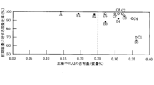
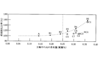
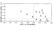
- FIG. 1 is a cross-sectional view schematically showing a nickel-hydrogen storage battery as an embodiment of the alkaline storage battery of the present invention. It is a graph which shows the relationship of the capacity
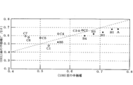
- the half-value width (° / 2 ⁇ ) of the peak at the (100) plane of the positive electrode active material (nickel hydroxide (Ni (OH) 2 )) in the nickel positive electrode and the half-value width of the peak at the (001) plane (° / 2 ⁇ ) is a graph showing the relationship.
- Nickel positive electrode The nickel positive electrode 11 was produced by filling nickel hydroxide and aluminum hydroxide in a predetermined amount of filling into the pores of a nickel sintered substrate.
- a nickel sintered substrate manufactured as follows is used.
- nickel slurry was prepared by mixing and kneading methyl cellulose (MC) as a thickener, polymer hollow microspheres (for example, having a pore size of 60 ⁇ m), and water with nickel powder.
- MC methyl cellulose
- polymer hollow microspheres for example, having a pore size of 60 ⁇ m
- the obtained sintered nickel substrate having a porosity of about 80% is impregnated with the following impregnating liquid and the alkali treatment with the alkaline treating liquid is repeated a predetermined number of times, thereby allowing the porous nickel sintered substrate to be porous.
- the sintered nickel positive electrode 11 filled with the positive electrode active material was produced by cutting into predetermined dimensions.
- a mixed nitrate solution prepared by mixing nickel nitrate, aluminum nitrate and zinc nitrate at a predetermined molar ratio (for example, 100: 5: 5) is used as the impregnation liquid, and the specific gravity is used as the alkali treatment liquid.
- a 1.3 aqueous solution of sodium hydroxide (NaOH) was used.
- the nickel sintered substrate was immersed in an impregnating solution, the impregnating solution was impregnated in the pores of the nickel sintered substrate, dried, and then immersed in an alkali processing solution to perform an alkali treatment.
- nickel salt and aluminum salt were converted into nickel hydroxide and aluminum hydroxide.
- the substrate was sufficiently washed with water to remove the alkaline solution and then dried.
- a series of positive electrode active material filling operations such as impregnation with an impregnation solution, drying, immersion in an alkaline treatment solution, washing with water, and drying are repeated five times, whereby a predetermined amount of the positive electrode active material is applied to the nickel sintered substrate. Filled.
- the aluminum (Al) content in the positive electrode active material gradually decreases from the surface of the nickel positive electrode toward the inside. become.
- a layer containing aluminum (Al) is formed only on the surface of the nickel positive electrode by immersing the nickel sintered substrate in a nitrate solution containing only aluminum nitrate after the final impregnation of the series of impregnation steps.
- the hydrogen storage alloy negative electrode 12 was prepared by applying a hydrogen storage alloy slurry to a negative electrode core made of punching metal.
- a hydrogen storage alloy lump (ingot) was heat-treated in an argon gas atmosphere to adjust the crystal structure in the ingot, and then mechanically pulverized in an inert atmosphere to obtain a hydrogen storage alloy powder.
- SBR styrene butadiene latex
- CMC carboxymethylcellulose
- the hydrogen storage alloy negative electrode 12 was produced by cutting.
- the stoichiometric ratio of the B component (molar ratio of Ni and Al) to the hydrogen storage alloy (the molar ratio of La and Mg) expressed as La 0.6 Sm 0.4 Mg 0.1 Ni 3.6 Al 0.05 is 3 .3 (AB 3.3 )) was used to make a hydrogen storage alloy negative electrode having a length of 1000 mm ⁇ height (width): 50 mm ⁇ thickness: 0.20 mm.
- Nickel-hydrogen storage battery Next, the nickel positive electrode 11 and the hydrogen storage alloy negative electrode 12 produced as described above were used, and a separator 13 made of a polyolefin non-woven fabric was interposed between them to form a spiral.
- the electrode group was produced.
- the core exposed part 11c of the nickel positive electrode 11 is exposed at the upper part of the spiral electrode group thus produced, and the core exposed part 12c of the hydrogen storage alloy electrode 12 is exposed at the lower part.
- the negative electrode current collector 14 is welded to the core exposed portion 12c exposed at the lower end surface of the obtained spiral electrode group, and the core exposed portion 11c of the nickel electrode 11 exposed at the upper end surface of the spiral electrode group.
- a positive electrode current collector 15 was welded onto the electrode body to obtain an electrode body.
- the negative electrode current collector 14 is attached to the outer can 17.
- the current collecting lead portion 15a extending from the positive electrode current collector 15 was also welded to the bottom portion of the sealing body 18 which also served as the positive electrode terminal and was fitted with the insulating gasket 19 on the outer peripheral portion.
- the sealing body 18 is provided with a positive electrode cap 18a, and a pressure valve (not shown) composed of a valve body 18b and a spring 18c, which are deformed when a predetermined pressure is reached, is disposed in the positive electrode cap 18a.
- the nickel-hydrogen storage battery 10 thus manufactured was charged to 110% of the theoretical capacity with a 1 It charging current, and then discharged with a 1 It discharging current until the battery voltage reached 0.9 V.
- the battery capacity was 6 Ah.
- the internal resistance value (DC resistance value: DCR) after discharge was 0.97 m ⁇ .
- the nickel-hydrogen storage battery 10 after discharge was disassembled, and the nickel positive electrode 11 was taken out. Thereafter, after removing the positive electrode active material from the nickel positive electrode 11, analysis was performed using a powder X-ray diffractometer (XRD) using Cu—K ⁇ .
- XRD powder X-ray diffractometer
- Ni (OH) 2 The half width of the peak at the (101) plane is 0.75 (° / 2 ⁇ ), the half width of the peak at the (100) plane is 0.76 (° / 2 ⁇ ), and (001) The half width of the peak at the plane is 0.68 (° / 2 ⁇ ), and the ratio of the half width of the peak at the (001) plane to the half width of the peak at the (100) plane ((001) plane / (100) plane) was found to be 0.89. Further, the content of aluminum (Al) and zinc (Zn) in the positive electrode active material was measured with an ICP (Inductively Coupled Plasma) emission spectroscopic analyzer for the dropped positive electrode active material.
- ICP Inductively Coupled Plasma
- the content of aluminum (Al) is 0.14% by mass with respect to the mass of the positive electrode active material
- the content of zinc (Zn) is based on the nickel (Ni) atoms of nickel hydroxide serving as the positive electrode active material. It turned out that it is 0.05 mass% with respect to it.
- battery A was not subjected to the partial charge / discharge cycle test. Moreover, what performed the partial charging / discharging cycle test over 1 month was set as battery B1. Similarly, the battery B2 was obtained by performing the partial charge / discharge cycle test over 3 months, the battery B3 was obtained by performing the partial charge / discharge cycle test over 4 months, and the partial charge / discharge cycle test 5 The battery B4 was obtained over a period of 6 months, and the battery B5 was obtained by performing a partial charge / discharge cycle test over a period of 6 months.
- the nickel-hydrogen storage batteries B1 to B5 are disassembled and the positive electrode active material is removed from the nickel positive electrode 11 in the same manner as described above, and then X-ray diffraction measurement and ICP analysis are performed using XRD. 2
- the half width of the peak at the (101) plane, the half width of the peak at the (100) plane, the half width of the peak at the (001) plane, and the half width of the peak at the (100) plane When the ratio of the half width of the peak on the (001) plane to the width and the content of aluminum (Al) with respect to the mass of the positive electrode active material were obtained, the results shown in Table 1 below were obtained.
- a standing test in which it was left in a predetermined temperature atmosphere was defined as C1 to C7.
- the partial charge / discharge cycle test as described above is performed for 5.4 months, charged to a voltage at which the SOC becomes 10%, and then left in a high temperature atmosphere at 60 ° C. for 0.6 months.
- the battery C1 was obtained (the ratio between the cycle test period and the standing period was 90:10).
- the partial charge / discharge cycle test as described above was performed for 1.2 months, charged to a voltage at which the SOC became 10%, and then left in a high temperature atmosphere at 60 ° C. for 4.8 months ( The battery C2 was obtained by setting the ratio of the cycle test period and the standing period to 20:80.
- the partial charge / discharge cycle test as described above was performed for 2.4 months, charged to a voltage at which the SOC became 10%, and then left in a high temperature atmosphere at 60 ° C. for 3.6 months ( The ratio between the cycle test period and the standing period was 40:60) and was designated as battery C3. Further, the partial charge / discharge cycle test as described above was conducted for 3.0 months, charged to a voltage at which the SOC became 10%, and then left in a high temperature atmosphere at 60 ° C. for 3.0 months ( The battery C4 was obtained by setting the ratio of the cycle test period and the standing period to 50:50.
- the partial charge / discharge cycle test as described above is performed for 3.6 months, charged to a voltage at which the SOC becomes 10%, and then left in a high temperature atmosphere at 25 ° C. for 14.4 months ( The ratio between the cycle test period and the standing period was 20:80) was designated as battery C5.
- the partial charge / discharge cycle test as described above is performed for 9.0 months, charged to a voltage at which the SOC becomes 10%, and then left in a high temperature atmosphere at 25 ° C. for 9.0 months ( The battery C6 was obtained by setting the ratio of the cycle test period and the standing period to 50:50.
- the partial charge / discharge cycle test as described above is performed for 2.4 months, charged to a voltage at which the SOC becomes 10%, and then left in a high temperature atmosphere at 45 ° C. for 9.6 months ( The ratio between the cycle test period and the standing period was 20:80) was designated as battery C7.
- the nickel-hydrogen storage batteries C1 to C7 are disassembled, the positive electrode active material is removed from the nickel positive electrode 11 in the same manner as described above, and then X-ray diffraction measurement and ICP analysis are performed using XRD, and Ni (OH 2 )
- X-ray diffraction measurement and ICP analysis are performed using XRD, and Ni (OH 2 )
- the half width of the peak at the (101) plane, the half width of the peak at the (100) plane, the half width of the peak at the (001) plane, and the half width of the peak at the (100) plane When the ratio of the half width of the peak on the (001) plane to the width and the content of aluminum (Al) with respect to the mass of the positive electrode active material were obtained, the results shown in Table 1 below were obtained.
- the content of aluminum (Al) in the positive electrode active material is plotted on the horizontal axis (X axis), and the half width of the peak on the (101) plane of nickel hydroxide (Ni (OH) 2 ) is plotted on the vertical axis.
- the results shown in FIG. 4 were obtained.
- the half width of the peak at (100) plane of the nickel hydroxide (Ni (OH) 2) in the horizontal axis (X axis) (001) plane of the nickel hydroxide (Ni (OH) 2)
- the half-value width of the peak at is plotted on the vertical axis (Y-axis) and plotted as a graph, the result shown in FIG. 5 was obtained.
- Table 1 below also shows the results of Battery A.
- the content of aluminum (Al) in the nickel positive electrode increases as the cycle test period becomes longer, and the initial capacity is increased. It can be seen that the capacity ratio tends to decrease. Further, the content of aluminum (Al) with respect to the mass of the positive electrode active material in the nickel positive electrode and the half width of the peak at the (101) plane of nickel hydroxide (Ni (OH) 2 ) serving as the positive electrode active material are correlated. You can also see that there is a relationship.
- the half width of the peak at the (101) plane of nickel hydroxide (Ni (OH) 2 ) that becomes the positive electrode active material tends to decrease. It can be seen that the crystallinity of nickel hydroxide (Ni (OH) 2 ) increases, the positive electrode resistance increases, and the battery capacity tends to decrease.
- the content of aluminum (Al) in the nickel positive electrode increases when the standing period is shorter than the period of the cycle test as in the battery C1.
- the decrease in the half width of the peak at the (101) plane of nickel hydroxide (Ni (OH) 2 ) increases accordingly. It can be seen that the battery capacity decreases as the positive electrode resistance increases.
- the increase factor of the positive electrode resistance is that aluminum (Al) eluted from the hydrogen storage alloy as the negative electrode active material is taken into the nickel positive electrode, and as a result, the content of aluminum (Al) in the nickel positive electrode increases. It will be.
- the half width of the peak of the (101) plane of nickel hydroxide (Ni (OH) 2 ) serving as the positive electrode active material decreases, and the crystallinity of nickel hydroxide (Ni (OH) 2 ) increases. It becomes. And it is thought that the crystallinity of nickel hydroxide (Ni (OH) 2 ) increases and the electron transfer in the positive electrode active material becomes difficult, which is a cause of an increase in positive electrode resistance.
- the ratio of the half width of the peak is 1 or more in the batteries C2 to C7, and the batteries B1 to In B5 and battery C1, the half width of the peak on the (001) plane relative to the half width of the peak on the (100) plane was 1 or less. From this, in the crystal structure of nickel hydroxide of the batteries C2 to C7, the crystallinity in the c-axis direction is low with respect to the a-axis, and the electron conductivity is good, so that the increase in the positive electrode resistance is suppressed. it is conceivable that.
- the amount of addition is desirably 0.25% by mass or less. This is because, when the amount of aluminum (Al) added during production is more than 0.25% by mass, the crystallinity is increased, and therefore the increase in positive electrode resistance is not suppressed even after the charge / discharge cycle test is performed. It is.
- zinc (Zn) is included by 0.05 mass% with respect to Ni atoms of Ni (OH) 2 serving as a positive electrode active material at the time of producing a nickel positive electrode.
- the addition amount of zinc (Zn) to be contained is desirably 0.05% by mass or less with respect to Ni atoms of Ni (OH) 2 serving as the positive electrode active material.
- the addition amount is less than 0.05% by mass with respect to Ni atoms of Ni (OH) 2 serving as the positive electrode active material, the crystallinity of Ni (OH) 2 is lowered and charge / discharge cycles are performed. This is because the increase in the positive electrode resistance can be suppressed even after the test.
- the added amount is more than 0.05% by mass with respect to Ni atoms of Ni (OH) 2 serving as the positive electrode active material, the crystallinity of Ni (OH) 2 becomes high, and a charge / discharge cycle is performed. This is because the crystallinity is maintained high even after the increase of the positive electrode resistance.
Landscapes
- Chemical & Material Sciences (AREA)
- Chemical Kinetics & Catalysis (AREA)
- Electrochemistry (AREA)
- General Chemical & Material Sciences (AREA)
- Engineering & Computer Science (AREA)
- Manufacturing & Machinery (AREA)
- Composite Materials (AREA)
- Battery Electrode And Active Subsutance (AREA)
- Secondary Cells (AREA)
Abstract
【課題】大電流でのパルス充放電サイクルを繰り返し行った後でも、ニッケル正極の抵抗増加を抑制して、電池容量を十分に確保できるようにする。 【解決手段】本発明のアルカリ蓄電池10は、水素吸蔵合金負極12にアルミニウム(Al)が含有されているとともに、ニッケル正極11にもAlが含有されており、所定の充放電サイクルが終了した状態において、ニッケル正極11に含有されたAlの含有量は正極活物質に対して0.25質量%以上であり、かつ、当該正極活物質のCu-Kαを用いた粉末X線回折においてNi(OH)2の(101)面でのピークの半価幅が0.5(°/2θ)以上になるように規制している。
Description
本発明は、ハイブリッド自動車(HEV)などの車両用途に好適なアルカリ蓄電池に係り、特に、水素吸蔵合金が負極活物質である水素吸蔵合金負極と、水酸化ニッケルが主成
分の正極活物質であるニッケル正極と、セパレータとからなる電極群をアルカリ電解液とともに電池容器内に収納されて密閉されたアルカリ蓄電池に関する。
分の正極活物質であるニッケル正極と、セパレータとからなる電極群をアルカリ電解液とともに電池容器内に収納されて密閉されたアルカリ蓄電池に関する。
近年、二次電池の用途は、例えば、携帯電話、パーソナルコンピュータ、電動工具、ハイブリッド自動車(HEV)など多岐に亘るようになり、これらの用途にアルカリ蓄電池が用いられるようになった。このようなアルカリ蓄電池において、負極活物質となる水素吸蔵合金としては、充放電サイクルを繰り返し行った後でも結晶構造の安定化に優れたアルミニウム(Al)を含有させた組成のものが用いられるようになった。
一方、ニッケル正極においては、正極活物質の主成分として水酸化ニッケル(Ni(OH)2)を用いることが一般的であるが、近年、さらなる高容量化の要望に応えるために、水酸化ニッケル(Ni(OH)2)にアルミニウム(Al)を添加することが、例えば、特許文献1(特開平10-172561号公報)にて提案されるようになった。
一方、ニッケル正極においては、正極活物質の主成分として水酸化ニッケル(Ni(OH)2)を用いることが一般的であるが、近年、さらなる高容量化の要望に応えるために、水酸化ニッケル(Ni(OH)2)にアルミニウム(Al)を添加することが、例えば、特許文献1(特開平10-172561号公報)にて提案されるようになった。
ところで、アルミニウム(Al)を含有した水素吸蔵合金を負極活物質とする水素吸蔵合金負極と、アルミニウム(Al)が含有された水酸化ニッケル(Ni(OH)2)を正極活物質とするニッケル正極とを備えたアルカリ蓄電池をハイブリッド自動車(HEV)等の用途に用いた場合、大電流でのパルス充放電サイクルが繰り返して行われることとなる。このような大電流でのパルス充放電サイクルが繰り返して行われると、従来の民生用機器の用途においてはそれほど問題とはならなかったことが問題になった。換言すると、HEV等の用途での大電流でのパルス充放電サイクルが行われると、電池の内部抵抗の増加が顕在化するようになり、この内部抵抗の増加に起因して、電池容量が低下するという
問題が生じるようになった。
問題が生じるようになった。
これは、このようなアルカリ蓄電池において充放電サイクルが行われると、水素吸蔵合金中のアルミニウム(Al)成分がアルカリ電解液中へ溶出するようになるが、大電流でのパルス充放電サイクルが行われると、アルミニウム(Al)成分の溶出量が格段に増加するためである。このように、アルカリ電解液中へ溶出するアルミニウム(Al)成分の溶出量が増加すると、対極となる正極活物質中のアルミニウム(Al)の含有量が増加するようになる。そして、アルミニウム(Al)の含有量が正極活物質中で増加すると、ニッケル正極の抵抗値が増大するようになり、結果として、電池容量が低下するためである。
そこで、本発明者等は、大電流でのパルス充放電サイクルを繰り返して行った後のアルカリ蓄電池を分解して、ニッケル正極の抵抗値が増大した要因の分析を行った。その結果、正極活物質内においてアルミニウム(Al)成分の含有量が初期から比較して増大していることが明らかになった。また、粉末X線解析分析より正極活物質となる水酸化ニッケル(Ni(OH)2)の(101)面のピークの半価幅が低下して、正極活物質である水酸化ニッケル(Ni(OH)2)の結晶性が増大していることが分かった。このことにより、ニッケル正極の抵抗値が増大する理由を確認することができた。
また、ニッケル正極の抵抗値の増加が抑制された正極活物質における粉末X線解析分析結果を確認したところ、(001)面のピークの半価幅が、(100)面のピークの半価幅に対して大きい結果となった。これは、水酸化ニッケル(Ni(OH)2)の結晶格子におけるa軸方向よりもc軸方向の方が結晶性が低いことを意味している。換言すると、水酸化ニッケル(Ni(OH)2)はc軸方向に対して積層の結晶構造を取ることが知られており、a軸方向に対してc軸方向での結晶性が低くなることで、層間での電子移動が容易となることから抵抗低減がなされていると推測される。
本発明は、大電流でのパルス充放電サイクルを繰り返して行った後でも、ニッケル正極の抵抗増加を抑制して、電池容量を十分に確保できるようにすることを目的としてなされたものである。
本発明のアルカリ蓄電池は、水素吸蔵合金を負極活物質とする水素吸蔵合金負極と、水酸化ニッケルを主成分正極活物質とするニッケル正極と、セパレータとからなる電極群をアルカリ電解液とともに電池容器内に収納されて密閉されている。そして、上記目的を達成するため、水素吸蔵合金負極にアルミニウム(Al)が含有されているとともに、ニッケル正極にもアルミニウム(Al)が含有されており、ニッケル正極に含有されたアルミニウム(Al)の含有量は正極活物質に対して0.25質量%以上であり、かつ、当該正極活物質のCu-Kαを用いた粉末X線回折においてNi(OH)2の(101)面でのピークの半価幅が0.5(°/2θ)以上になるように規制している。また、ニッケル正極のCu-Kαを用いた粉末X線回折においてNi(OH)2の(001)面のピークの半価幅が(100)面のピークの半価幅より大であるように規制している。
ここで、正極抵抗に影響を及ぼす正極活物質層内のアルミニウム(Al)の含有量が正極活物質の質量に対して0.25質量%以上の範囲においても、アルミニウム(Al)の含有量と正極活物質となる水酸化ニッケル(Ni(OH)2)の半価幅の関係を規定することにより正極抵抗の増加を抑制可能であるという知見を得た。この場合、正極活物質内のアルミニウム(Al)の含有量が、0.25質量%以上含有されている場合においては、正極活物質となる水酸化ニッケル(Ni(OH)2)のCu-Kαを用いた粉末X線回折において(101)面でのピークの半価幅が0.5(°/2θ)未満であると、正極活物質の半価幅が小さくて、結晶性が高くなることとなり、正極抵抗が高くなる。そのため、充放電サイクル後の電池容量が十分に得られない結果となる。
一方、正極活物質内のアルミニウム(Al)の含有量が、0.25質量%以上含有されている場合であっても、正極活物質となる水酸化ニッケル(Ni(OH)2)のCu-Kαを用いた粉末X線回折において(101)面でのピークの半価幅が0.5(°/2θ)以上であると、正極活物質の半価幅が大きくて、結晶性が低くなることとなり、正極抵抗増大が抑制されることとなり、充放電サイクル後の電池容量が十分になるという結果が得られた。
ここで、ニッケル正極には正極活物質となる水酸化ニッケル(Ni(OH)2)のニッケル(Ni)原子に対して0.05質量%以下だけ亜鉛(Zn)が含有されているのが望ましい。これは、ニッケル正極における水酸化ニッケル(Ni(OH)2)のニッケル(Ni)原子に対して0.05質量%以下だけ亜鉛(Zn)が含有されていると、水酸化ニッケル(Ni(OH)2)の結晶性が低く、充放電サイクル試験を行った後においても正極抵抗増大抑制効果が顕著に認められるという結果が得られたからである。なお、ニッケル正極における水酸化ニッケル(Ni(OH)2)のニッケル(Ni)原子に対して0.05質量%よりも多くの亜鉛(Zn)が含有されていると、水酸化ニッケル(Ni(OH)2)の結晶性が高くなって、充放電サイクル試験を行った後においても結晶性が高く維持され、正極抵抗増大が抑制されないという結果が得られたからである。
また、正極活物質のCu-Kαを用いた粉末X線回折において水酸化ニッケル(Ni(OH)2)の(001)面のピークの半価幅が(100)面のピークの半価幅より大であることで、ニッケル正極の抵抗の増大が抑制されるので好ましい。
この場合、ニッケル正極の表面から内部に向けてアルミニウム(Al)の含有量が漸減するように存在させるのが望ましい。また、ニッケル正極は当該正極の表面より所定の距離までにアルミニウム(Al)の含有層が形成されているのが望ましい。
この場合、ニッケル正極の表面から内部に向けてアルミニウム(Al)の含有量が漸減するように存在させるのが望ましい。また、ニッケル正極は当該正極の表面より所定の距離までにアルミニウム(Al)の含有層が形成されているのが望ましい。
本発明においては、正極活物質層内のアルミニウム(Al)の含有量が正極活物質の質量に対して0.25質量%以上の範囲においても、アルミニウム(Al)の含有量と正極活物質となる水酸化ニッケル(Ni(OH)2)の(101)面でのピークの半価幅の関係を規定することにより、充放電サイクルを繰り返した後においても、ニッケル正極の抵抗増加による容量低下を抑制することが可能となる。
ついで、本発明の実施の形態を以下に詳細に説明するが、本発明はこれに限定されるものでなく、その要旨を変更しない範囲で適宜変更して実施することができる。
1.ニッケル正極
ニッケル正極11は、ニッケル焼結基板の多孔内に水酸化ニッケルと水酸化アルミニウムとが所定の充填量になるように充填して作製した。この場合、ニッケル焼結基板は以下のようにして作製したものを用いている。例えば、ニッケル粉末に、増粘剤となるメチルセルロース(MC)と高分子中空微小球体(例えば、孔径が60μmのもの)と水とを混合、混練してニッケルスラリーを作製した。ついで、ニッケルめっき鋼板からなるパンチングメタルの両面にニッケルスラリーを所定の厚みになるように塗着した後、還元性雰囲気中で1000℃で加熱して、増粘剤や高分子中空微小球体を消失させるとともにニッケル粉末同士を焼結させることにより多孔度が約80%となるニッケル焼結基板が得られる
。
そして、得られた多孔度が約80%のニッケル焼結基板に以下のような含浸液を含浸する含浸処理と、アルカリ処理液によるアルカリ処理とを所定回数繰り返すことにより、ニッケル焼結基板の多孔内に所定量の水酸化ニッケルと水酸化アルミニウムとを充填した後、所定の寸法に裁断することにより、正極活物質が充填された焼結式ニッケル正極11を作製した。この場合、含浸液としては、硝酸ニッケルと硝酸アルミニウムと硝酸亜鉛とを所定のモル比(例えば、100:5:5)となるように調製した混合硝酸塩溶液を用い、アルカリ処理液としては、比重が1.3の水酸化ナトリウム(NaOH)水溶液を用いた。
そして、ニッケル焼結基板を含浸液に浸漬して、ニッケル焼結基板の細孔内に含浸液を含浸させた後、乾燥させ、ついで、アルカリ処理液に浸漬してアルカリ処理を行った。これにより、ニッケル塩やアルミニウム塩を水酸化ニッケルや水酸化アルミニウムに転換させた。この後、充分に水洗してアルカリ溶液を除去した後、乾燥させた。このような、含浸液の含浸、乾燥、アルカリ処理液への浸漬、水洗、および乾燥という一連の正極活物質の充填操作を5回繰り返すことにより、所定量の正極活物質をニッケル焼結基板に充填させた。
ここで、上述した混合硝酸塩溶液の硝酸アルミニウム濃度を、一連の含浸工程毎に増やしていくことにより、正極活物質内のアルミニウム(Al)含有量がニッケル正極の表面から内部に向けて漸減するようになる。また、一連の含浸工程の最終含浸後に、硝酸アルミニウムのみ含む硝酸塩溶液中にニッケル焼結基板を浸漬することにより、ニッケル正極の表面のみにアルミニウム(Al)を含む層が形成されることとなる。
2.水素吸蔵合金負極
水素吸蔵合金負極12はパンチングメタルからなる負極芯体に水素吸蔵合金スラリーを塗布して作製した。この場合、例えば、水素吸蔵合金の塊(インゴット)をアルゴンガス雰囲気で熱処理を行ってインゴットにおける結晶構造を調整した後、不活性雰囲気中で機械的に粉砕して水素吸蔵合金粉末とした。この後、得られた水素吸蔵合金粉末100質量部に対し、非水溶性高分子結着剤としてのSBR(スチレンブタジエンラテックス)を0.5質量部と、増粘剤としてCMC(カルボキシメチルセルロース)を0.03質量部と、適量の純水を加えて混練して、水素吸蔵合金スラリーを調製した。そして、得られた水素吸蔵合金スラリーをパンチングメタル(ニッケルメッキ鋼板製)からなる負極芯体の両面に塗着した後、乾燥させ、所定の充填密度になるように圧延した後、所定の寸法に裁断して水素吸蔵合金負極12を作製した。
水素吸蔵合金負極12はパンチングメタルからなる負極芯体に水素吸蔵合金スラリーを塗布して作製した。この場合、例えば、水素吸蔵合金の塊(インゴット)をアルゴンガス雰囲気で熱処理を行ってインゴットにおける結晶構造を調整した後、不活性雰囲気中で機械的に粉砕して水素吸蔵合金粉末とした。この後、得られた水素吸蔵合金粉末100質量部に対し、非水溶性高分子結着剤としてのSBR(スチレンブタジエンラテックス)を0.5質量部と、増粘剤としてCMC(カルボキシメチルセルロース)を0.03質量部と、適量の純水を加えて混練して、水素吸蔵合金スラリーを調製した。そして、得られた水素吸蔵合金スラリーをパンチングメタル(ニッケルメッキ鋼板製)からなる負極芯体の両面に塗着した後、乾燥させ、所定の充填密度になるように圧延した後、所定の寸法に裁断して水素吸蔵合金負極12を作製した。
なお、一般式がLa0.6Sm0.4Mg0.1Ni3.6Al0.05と表される水素吸蔵合金(A成分(LaとMgのモル比)に対するB成分(NiとAlのモル比)の量論比は3.3(AB3.3))を用い、長さ:1000mm×高さ(幅):50mm×厚み:0.20mmになるように作製したものを水素吸蔵合金負極とした。
3.ニッケル-水素蓄電池
ついで、上述のようにして作製したニッケル正極11と、水素吸蔵合金負極12とを用い、これらの間に、ポリオレフィン製不織布からなるセパレータ13を介在させて渦巻状に巻回して渦巻状電極群を作製した。なお、このようにして作製された渦巻状電極群の上部にはニッケル正極11の芯体露出部11cが露出しており、その下部には水素吸蔵合金電極12の芯体露出部12cが露出している。ついで、得られた渦巻状電極群の下端面に露出する芯体露出部12cに負極集電体14を溶接するとともに、渦巻状電極群の上端面に露出するニッケル電極11の芯体露出部11cの上に正極集電体15を溶接して、電極体とした。
ついで、上述のようにして作製したニッケル正極11と、水素吸蔵合金負極12とを用い、これらの間に、ポリオレフィン製不織布からなるセパレータ13を介在させて渦巻状に巻回して渦巻状電極群を作製した。なお、このようにして作製された渦巻状電極群の上部にはニッケル正極11の芯体露出部11cが露出しており、その下部には水素吸蔵合金電極12の芯体露出部12cが露出している。ついで、得られた渦巻状電極群の下端面に露出する芯体露出部12cに負極集電体14を溶接するとともに、渦巻状電極群の上端面に露出するニッケル電極11の芯体露出部11cの上に正極集電体15を溶接して、電極体とした。
ついで、得られた電極体を鉄にニッケルメッキを施した有底筒状の外装缶(底面の外面は負極外部端子となる)17内に収納した後、負極集電体14を外装缶17の内底面に溶接した。一方、正極集電体15より延出する集電リード部15aを正極端子を兼ねるとともに外周部に絶縁ガスケット19が装着された封口体18の底部に溶接した。なお、封口体18には正極キャップ18aが設けられていて、この正極キャップ18a内に所定の圧力になると変形する弁体18bとスプリング18cよりなる圧力弁(図示せず)が配置されている。
ついで、外装缶17の上部外周部に環状溝部17aを形成した後、アルカリ電解液を注液し、外装缶17の上部に形成された環状溝部17aの上に封口体18の外周部に装着された絶縁ガスケット19を載置した。この後、外装缶17の開口端縁17bをかしめることにより、公称容量は6Ah(直径が32mmで、高さが60mm)のニッケル-水素蓄電池10を作製した。
このように作製したニッケル-水素蓄電池10を1Itの充電々流で理論容量の110%まで充電した後、1Itの放電々流で電池電圧が0.9Vになるまで放電させ、放電時間から初期の電池容量を求めると6Ahであった。これと同時に、放電後の内部抵抗値(直流抵抗値:DCR)を求めると0.97mΩであった。また、放電後のニッケル-水素蓄電池10を解体して、ニッケル正極11を取り出した。この後、このニッケル正極11から正極活物質を脱落させた後、Cu-Kαを用いた粉末X線回折装置(XRD:X-Ray Diffractometer)を用いて解析を行った結果、Ni(OH)2の(101)面でのピークの半価幅は0.75(°/2θ)であり、(100)面でのピークの半価幅は0.76(°/2θ)であり、(001)面でのピークの半価幅は0.68(°/2θ)であり、(100)面でのピークの半価幅に対する(001)面でのピークの半価幅の比((001)面/(100)面)は0.89であることが分かった。また、脱落させた正極活物質をICP(Inductively Coupled Plasma)発光分光分析装置により、正極活物質内のアルミニウム(Al)および亜鉛(Zn)の含有量を測定した。その結果、アルミニウム(Al)の含有量は正極活物質の質量に対して0.14質量%であり、亜鉛(Zn)の含有量は正極活物質となる水酸化ニッケルのニッケル(Ni)原子に対して0.05質量%であることが分かった。
4.電池試験(充放電サイクル試験および放置試験)
ついで、上述のようにして作製したニッケル-水素蓄電池10を用い、45℃の温度雰囲気において、電池容量の20~90%のSOC(State of Charge:充電深度)範囲で部分充放電サイクル試験(10Itの充電々流にてSOCが90%となる電圧まで充電した後、10Itの放電々流にてSOCが20%となる電圧まで放電させるというサイクル試験)を行った。そして、このような部分充放電サイクルを所定期間に亘り繰り返して行った。
ついで、上述のようにして作製したニッケル-水素蓄電池10を用い、45℃の温度雰囲気において、電池容量の20~90%のSOC(State of Charge:充電深度)範囲で部分充放電サイクル試験(10Itの充電々流にてSOCが90%となる電圧まで充電した後、10Itの放電々流にてSOCが20%となる電圧まで放電させるというサイクル試験)を行った。そして、このような部分充放電サイクルを所定期間に亘り繰り返して行った。
ここで、部分充放電サイクル試験を行なわなかったものを電池Aとした。また、部分充放電サイクル試験を1ヶ月間に亘って行ったものを電池B1とした。同様に、部分充放電サイクル試験を3ヶ月間に亘って行ったものを電池B2とし、部分充放電サイクル試験を4ヶ月間に亘って行ったものを電池B3とし、部分充放電サイクル試験を5ヶ月間に亘って行ったものを電池B4とし、部分充放電サイクル試験を6ヶ月間に亘って行ったものを電池B5とした。
ついで、上述の如き充放電サイクル試験を行った後のニッケル-水素蓄電池B1~B5の内部抵抗値(直流抵抗値:DCR)を測定するとともに、先に求めた電池Aの内部抵抗値(直流抵抗値:DCR)との比率を求めると、下記の表1に示すような結果となった。また、上述の如き充放電サイクル試験を行った後、これらの電池B1~B5を1Itの充電々流でSOC110%まで充電した後、1Itの放電々流で電池電圧が0.9Vになるまで放電させ、放電時間から充放電サイクル試験後の電池容量を求め、先に求めた初期容量との比を初期容量比(対電池A比)として求めると、下記の表1に示すような結果となった。この後、ニッケル-水素蓄電池B1~B5を解体して、上述と同様にしてニッケル正極11から正極活物質を脱落させた後、XRDを用いてX線回折測定およびICP分析を行い、Ni(OH)2の(101)面でのピークの半価幅、(100)面でのピークの半価幅、(001)面でのピークの半価幅、および(100)面でのピークの半価幅に対する(001)面でのピークの半価幅の比、ならびに正極活物質の質量に対するアルミニウム(Al)の含有量を求めると、下記の表1に示すような結果となった。
一方、上述の如き部分充放電サイクル試験を行なった後、初期容量に対するSOCが10%となる電圧まで充電した後、所定の温度雰囲気中に放置する放置試験を行ったものをC1~C7とした。この場合、上述の如き部分充放電サイクル試験を5.4ヶ月間に亘って行い、SOCが10%となる電圧まで充電した後、60℃の高温雰囲気中に0.6ヶ月間に亘って放置(サイクル試験期間と放置期間の比率は90対10となる)したものを電池C1とした。また、上述の如き部分充放電サイクル試験を1.2ヶ月間に亘って行い、SOCが10%となる電圧まで充電した後、60℃の高温雰囲気中に4.8ヶ月間に亘って放置(サイクル試験期間と放置期間の比率は20対80となる)したものを電池C2とした。
また、上述の如き部分充放電サイクル試験を2.4ヶ月間に亘って行い、SOCが10%となる電圧まで充電した後、60℃の高温雰囲気中に3.6ヶ月間に亘って放置(サイクル試験期間と放置期間の比率は40対60となる)したものを電池C3とした。また、上述の如き部分充放電サイクル試験を3.0ヶ月間に亘って行い、SOCが10%となる電圧まで充電した後、60℃の高温雰囲気中に3.0ヶ月間に亘って放置(サイクル試験期間と放置期間の比率は50対50となる)したものを電池C4とした。また、上述の如き部分充放電サイクル試験を3.6ヶ月間に亘って行ない、SOCが10%となる電圧まで充電した後、25℃の高温雰囲気中に14.4ヶ月間に亘って放置(サイクル試験期間と放置期間の比率は20対80となる)したものを電池C5とした。
さらに、上述の如き部分充放電サイクル試験を9.0ヶ月間に亘って行ない、SOCが10%となる電圧まで充電した後、25℃の高温雰囲気中に9.0ヶ月間に亘って放置(サイクル試験期間と放置期間の比率は50対50となる)したものを電池C6とした。また、上述の如き部分充放電サイクル試験を2.4ヶ月間に亘って行ない、SOCが10%となる電圧まで充電した後、45℃の高温雰囲気中に9.6ヶ月間に亘って放置(サイクル試験期間と放置期間の比率は20対80となる)したものを電池C7とした。
ついで、上述の如き充放電サイクル試験を行った後のニッケル-水素蓄電池C1~C7の内部抵抗値(直流抵抗値:DCR)を測定するとともに、先に求めた電池Aの内部抵抗値(直流抵抗値:DCR)との比率を求めると、下記の表1に示すような結果となった。また、上述の如き充放電サイクル試験と放置試験を行った後、これらの電池C1~C7を1Itの充電々流でSOC110%まで充電した後、1Itの放電々流で電池電圧が0.9Vになるまで放電させ、放電時間から放置試験後の電池容量を求め、先に求めた初期容量との比を初期容量比(対電池A比)として求めると、下記の表1に示すような結果となった。この後、ニッケル-水素蓄電池C1~C7を解体して、上述と同様にしてニッケル正極11から正極活物質を脱落させた後、XRDを用いてX線回折測定およびICP分析を行い、Ni(OH)2の(101)面でのピークの半価幅、(100)面でのピークの半価幅、(001)面でのピークの半価幅、および(100)面でのピークの半価幅に対する(001)面でのピークの半価幅の比、ならびに正極活物質の質量に対するアルミニウム(Al)の含有量を求めると、下記の表1に示すような結果となった。
そして、下記の表1の結果に基づき、正極活物質内のアルミニウム(Al)の含有量を横軸(X軸)にプロットし、電池容量比率(%)を縦軸(Y軸)にプロットしてグラフにすると、図2に示すような結果となった。また、正極活物質内のアルミニウム(Al)の含有量を横軸(X軸)にプロットし、電池抵抗比率(%)を縦軸(Y軸)にプロットしてグラフにすると、図3に示すような結果となった。さらに、正極活物質内のアルミニウム(Al)の含有量を横軸(X軸)にプロットし、水酸化ニッケル(Ni(OH)2)の(101)面でのピークの半価幅を縦軸(Y軸)にプロットしてグラフにすると、図4に示すような結果となった。また、水酸化ニッケル(Ni(OH)2)の(100)面でのピークの半価幅を横軸(X軸)にプロットし、水酸化ニッケル(Ni(OH)2)の(001)面でのピークの半価幅を縦軸(Y軸)にプロットしてグラフにすると、図5に示すような結果となった。なお、下記の表1には電池Aの結果も併せて示している。
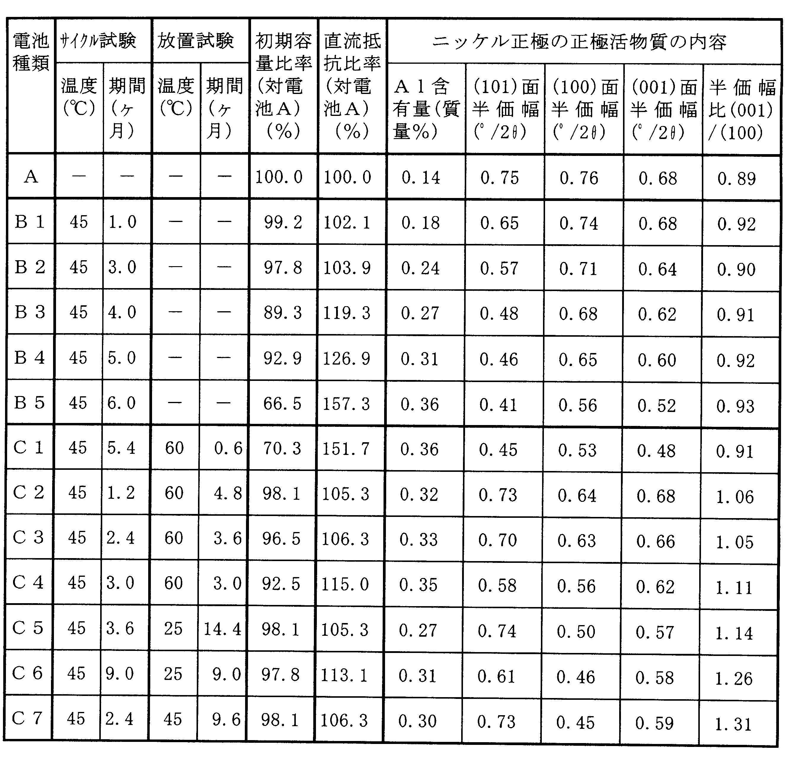
上記表1の電池Aと、電池B1~B5との結果から明らかなように、サイクル試験の期間が長くなるに伴ってニッケル正極中のアルミニウム(Al)の含有量が増加して、初期容量に対する容量比率が低下する傾向にあることが分かる。また、ニッケル正極中の正極活物質の質量に対するアルミニウム(Al)の含有量と正極活物質となる水酸化ニッケル(Ni(OH)2)の(101)面でのピークの半価幅とは相関関係が有ることも分かる。即ち、ニッケル正極中のアルミニウム(Al)の含有量が増加すると、それに伴い正極活物質となる水酸化ニッケル(Ni(OH)2)の(101)面でのピークの半価幅が低下する傾向にあり、水酸化ニッケル(Ni(OH)2)の結晶性が増大して、正極抵抗が増大し、電池容量が低下する傾向にあることが分かる。
この場合、電池A,B1と、電池B2~B5との結果から、ニッケル正極中のアルミニウム(Al)の含有量が正極活物質の質量に対して0.25質量%未満であると、電池容量の低下は殆ど認められないことが分かる。これに対して、電池B2~B5のようにニッケル正極中のアルミニウム(Al)の含有量が正極活物質の質量に対して0.25質量%以上になると、水酸化ニッケル(Ni(OH)2)の(101)面でのピークの半価幅が0.5(°/2θ)以下となって、正極活物質となる水酸化ニッケル(Ni(OH)2)の結晶性が増大し、正極抵抗が増加して、結局、電池容量が低下することとなる。
一方、電池C1のように、放置期間がサイクル試験の期間よりも短くなると、ニッケル正極中のアルミニウム(Al)の含有量が多くなることが分かる。そして、ニッケル正極中のアルミニウム(Al)の含有量が多くなると、それに伴って水酸化ニッケル(Ni(OH)2)の(101)面でのピークの半価幅の低下が大きくなって結晶性が増大し、正極抵抗の増加により電池容量が低下するという結果となることが分かる。
これに対して、電池C2~電池C7のように、放置期間がサイクル試験の期間と同等かそれ以上に長くなると、ニッケル正極中のアルミニウム(Al)の含有量の増加は認められるものの正極活物質となる水酸化ニッケル(Ni(OH)2)の(101)面のピークの半価幅の低下が小さいことが分かる。そして、水酸化ニッケル(Ni(OH)2)の(101)面のピークの半価幅の低下が小さいことにより、正極抵抗の増加は小さいものとなって、電池容量の低下も小さい結果となっていることが分かる。
ここで、正極抵抗の増加要因は、負極活物質である水素吸蔵合金から溶出したアルミニウム(Al)がニッケル正極内に取り込まれ、この結果、ニッケル正極中のアルミニウム(Al)の含有量が増加することとなる。これにより、正極活物質となる水酸化ニッケル(Ni(OH)2)の(101)面のピークの半価幅が減少し、水酸化ニッケル(Ni(OH)2)の結晶性が増大することとなる。そして、水酸化ニッケル(Ni(OH)2)の結晶性が増大し、正極活物質内での電子移動が困難となることで、正極抵抗増大の要因と考えられている。このため、正極抵抗の増加を抑制するためには、水酸化ニッケル(Ni(OH)2)の(101)面のピークの半価幅を大きく維持して、水酸化ニッケル(Ni(OH)2)の結晶性の増大を抑制させればよいこととなる。
また、(100)面のピークの半価幅に対する(001)面のピークの半価幅を計算した結果、電池C2~電池C7ではピークの半価幅の比率が1以上であり、電池B1~B5、電池C1においては(100)面のピークの半価幅に対する(001)面のピークの半価幅は1以下であった。このことから、電池C2~電池C7の水酸化ニッケルの結晶構造において、a軸に対しc軸方向での結晶性が低いことから電子伝導性が良好であることから正極抵抗増大が抑制されていると考えられる。
以上の結果を総合勘案すると、ニッケル正極中のアルミニウム(Al)の含有量が正極活物質の質量に対して0.25質量%以上であっても、Cu-Kαを用いた粉末X線回折において、正極活物質となる水酸化ニッケル(Ni(OH)2)の(101)面のピークの半価幅を0.5(°/2θ)以上に維持できれば、正極抵抗の増加は小さいものとなって、電池容量の低下を抑制することが可能であるということができる。
なお、上述した実施の形態においては、ニッケル正極の作製時にアルミニウム(Al)を正極活物質の質量に対して0.14質量%だけ含有させる例について説明したが、作製時に含有させるアルミニウム(Al)の添加量は0.25質量%以下とするのが望ましい。これは、作製時に含有させるアルミニウム(Al)の添加量が0.25質量%より多くなると、結晶性が高くなることから充放電サイクル試験を行った後も正極抵抗増大が抑制されない結果となるためである。
また、上述した実施の形態においては、ニッケル正極の作製時に亜鉛(Zn)を正極活物質となるNi(OH)2のNi原子に対して0.05質量%だけ含有させる例について説明したが、含有させる亜鉛(Zn)の添加量は正極活物質となるNi(OH)2のNi原子に対して0.05質量%以下にするのが望ましい。これは正極活物質となるNi(OH)2のNi原子に対して0.05質量%よりも少ない添加量であると、Ni(OH)2の結晶性が低くなって、充放電サイクルを行った後においても正極抵抗が増大することを抑制できたためである。一方、正極活物質となるNi(OH)2のNi原子に対して0.05質量%よりも多い添加量であると、Ni(OH)2の結晶性が高くなって、充放電サイクルを行った後においても結晶性が高く維持されて正極抵抗が増大するためである。
11…ニッケル電極、11c…芯体露出部、12…水素吸蔵合金電極、12c…芯体露出部、13…セパレータ、14…負極集電体、15…正極集電体、15a…集電リード部、17…外装缶、17a…環状溝部、17b…開口端縁、18…封口体、18a…正極キャップ、18b…弁板、18c…スプリング、19…絶縁ガスケット
Claims (5)
- 水素吸蔵合金を負極活物質とする水素吸蔵合金負極と、水酸化ニッケルを主成分正極活物質とするニッケル正極と、セパレータとからなる電極群をアルカリ電解液とともに電池容器内に収納されて密閉されたアルカリ蓄電池であって、
前記水素吸蔵合金負極にアルミニウム(Al)が含有されているとともに、前記ニッケル正極にもアルミニウム(Al)が含有されており、
前記ニッケル正極に含有されたアルミニウム(Al)の含有量は正極活物質に対して0.25質量%以上であり、かつ、当該正極活物質のCu-Kαを用いた粉末X線回折においてNi(OH)2の(101)面でのピークの半価幅が0.5(°/2θ)以上であることを特徴とするアルカリ蓄電池。 - 前記ニッケル正極のCu-Kαを用いた粉末X線回折においてNi(OH)2の(001)面のピークの半価幅が(100)面のピークの半価幅より大であることを特徴とする請求項1に記載のアルカリ蓄電池。
- 前記ニッケル正極には正極活物質となる水酸化ニッケルのニッケル(Ni)原子に対して0.05質量%以下だけ亜鉛(Zn)が含有されていることを特徴とする請求項1または請求項2に記載のアルカリ蓄電池。
- 前記ニッケル正極の表面から内部に向けて前記アルミニウム(Al)の含有量が漸減していることを特徴とする請求項1から請求項3のいずれかに記載のアルカリ蓄電池。
- 前記ニッケル正極は当該正極の表面より所定の距離までにアルミニウム(Al)の含有層が形成されていることを特徴とする請求項1から請求項4のいずれかに記載のアルカリ
蓄電池。
Priority Applications (1)
| Application Number | Priority Date | Filing Date | Title |
|---|---|---|---|
| US13/989,958 US9209457B2 (en) | 2010-11-30 | 2011-11-29 | Alkaline storage battery |
Applications Claiming Priority (4)
| Application Number | Priority Date | Filing Date | Title |
|---|---|---|---|
| JP2010266191 | 2010-11-30 | ||
| JP2010-266191 | 2010-11-30 | ||
| JP2011-258562 | 2011-11-28 | ||
| JP2011258562A JP5868669B2 (ja) | 2010-11-30 | 2011-11-28 | アルカリ蓄電池 |
Publications (1)
| Publication Number | Publication Date |
|---|---|
| WO2012073933A1 true WO2012073933A1 (ja) | 2012-06-07 |
Family
ID=46171863
Family Applications (1)
| Application Number | Title | Priority Date | Filing Date |
|---|---|---|---|
| PCT/JP2011/077480 Ceased WO2012073933A1 (ja) | 2010-11-30 | 2011-11-29 | アルカリ蓄電池 |
Country Status (3)
| Country | Link |
|---|---|
| US (1) | US9209457B2 (ja) |
| JP (1) | JP5868669B2 (ja) |
| WO (1) | WO2012073933A1 (ja) |
Families Citing this family (4)
| Publication number | Priority date | Publication date | Assignee | Title |
|---|---|---|---|---|
| JP6024295B2 (ja) * | 2012-08-30 | 2016-11-16 | 三洋電機株式会社 | アルカリ蓄電池 |
| CN104584280A (zh) * | 2012-09-26 | 2015-04-29 | 松下知识产权经营株式会社 | 碱性蓄电池用正极活性物质、含有该正极活性物质的碱性蓄电池用正极、碱性蓄电池以及镍氢蓄电池 |
| JP6736065B2 (ja) * | 2018-11-15 | 2020-08-05 | 日本重化学工業株式会社 | アルカリ蓄電池用水素吸蔵合金およびそれを用いたアルカリ蓄電池 |
| CN113314697A (zh) * | 2021-05-27 | 2021-08-27 | 珠海冠宇电池股份有限公司 | 一种电芯和电池 |
Citations (5)
| Publication number | Priority date | Publication date | Assignee | Title |
|---|---|---|---|---|
| JPH04328257A (ja) * | 1991-04-25 | 1992-11-17 | Toshiba Battery Co Ltd | ペースト式ニッケル極およびアルカリ蓄電池 |
| JPH0757730A (ja) * | 1993-08-19 | 1995-03-03 | Toshiba Battery Co Ltd | アルカリ蓄電池 |
| JP2002270167A (ja) * | 2001-03-13 | 2002-09-20 | Matsushita Electric Ind Co Ltd | アルカリ蓄電池用正極活物質、正極および正極の製造法 |
| JP2003187793A (ja) * | 2001-12-21 | 2003-07-04 | Yuasa Corp | アルカリ蓄電池用ニッケル電極活物質、ニッケル電極およびアルカリ蓄電池。 |
| JP2008053222A (ja) * | 2006-08-23 | 2008-03-06 | Matsushita Electric Ind Co Ltd | 水酸化ニッケル粉末、オキシ水酸化ニッケル粉末、これらの製造方法およびアルカリ乾電池 |
Family Cites Families (1)
| Publication number | Priority date | Publication date | Assignee | Title |
|---|---|---|---|---|
| KR100231525B1 (ko) | 1996-12-13 | 1999-11-15 | 손욱 | 니켈 계열 전지의 양극용 활물질 및 이의 제조 방법 |
-
2011
- 2011-11-28 JP JP2011258562A patent/JP5868669B2/ja active Active
- 2011-11-29 WO PCT/JP2011/077480 patent/WO2012073933A1/ja not_active Ceased
- 2011-11-29 US US13/989,958 patent/US9209457B2/en active Active
Patent Citations (5)
| Publication number | Priority date | Publication date | Assignee | Title |
|---|---|---|---|---|
| JPH04328257A (ja) * | 1991-04-25 | 1992-11-17 | Toshiba Battery Co Ltd | ペースト式ニッケル極およびアルカリ蓄電池 |
| JPH0757730A (ja) * | 1993-08-19 | 1995-03-03 | Toshiba Battery Co Ltd | アルカリ蓄電池 |
| JP2002270167A (ja) * | 2001-03-13 | 2002-09-20 | Matsushita Electric Ind Co Ltd | アルカリ蓄電池用正極活物質、正極および正極の製造法 |
| JP2003187793A (ja) * | 2001-12-21 | 2003-07-04 | Yuasa Corp | アルカリ蓄電池用ニッケル電極活物質、ニッケル電極およびアルカリ蓄電池。 |
| JP2008053222A (ja) * | 2006-08-23 | 2008-03-06 | Matsushita Electric Ind Co Ltd | 水酸化ニッケル粉末、オキシ水酸化ニッケル粉末、これらの製造方法およびアルカリ乾電池 |
Also Published As
| Publication number | Publication date |
|---|---|
| US20130295460A1 (en) | 2013-11-07 |
| US9209457B2 (en) | 2015-12-08 |
| JP2012134134A (ja) | 2012-07-12 |
| JP5868669B2 (ja) | 2016-02-24 |
Similar Documents
| Publication | Publication Date | Title |
|---|---|---|
| JP5743780B2 (ja) | 円筒型ニッケル−水素蓄電池 | |
| JP5241188B2 (ja) | アルカリ蓄電池システム | |
| JP2011233423A (ja) | アルカリ蓄電池 | |
| JP5196938B2 (ja) | アルカリ蓄電池システム | |
| JP5405167B2 (ja) | アルカリ蓄電池システム | |
| JP5868669B2 (ja) | アルカリ蓄電池 | |
| CN106463786A (zh) | 镍氢二次电池 | |
| JP5322392B2 (ja) | 水素吸蔵合金電極およびその製造方法ならびにアルカリ蓄電池 | |
| JP5717125B2 (ja) | アルカリ蓄電池 | |
| JP5849768B2 (ja) | アルカリ蓄電池及びアルカリ蓄電池システム | |
| JP2012238565A (ja) | アルカリ蓄電池 | |
| JP6024295B2 (ja) | アルカリ蓄電池 | |
| JP2022041906A (ja) | 水素吸蔵合金、この水素吸蔵合金を含む負極及びこの負極を含むニッケル水素二次電池 | |
| JP4127990B2 (ja) | アルカリ蓄電池用ニッケル極、アルカリ蓄電池用ニッケル極の製造方法及びアルカリ蓄電池 | |
| JP5147235B2 (ja) | ニッケル水素蓄電池 | |
| WO2014050075A1 (ja) | 蓄電池システム。 | |
| JP5752487B2 (ja) | アルカリ蓄電池およびアルカリ蓄電池システム | |
| JP6263983B2 (ja) | アルカリ蓄電池及びその製造方法 | |
| CN115411265B (zh) | 储氢合金负极以及包含储氢合金负极的镍氢二次电池 | |
| JP4420653B2 (ja) | ニッケル・水素蓄電池 | |
| JP3954822B2 (ja) | アルカリ蓄電池用ニッケル極、アルカリ蓄電池用ニッケル極の製造方法及びアルカリ蓄電池 | |
| JP2024131037A (ja) | ニッケル水素二次電池 | |
| JP2024000748A (ja) | アルカリ蓄電池用正極板、及びアルカリ蓄電池 | |
| KR20250028150A (ko) | 고농도 질소를 함유하는 금속-탄소 복합재 및 이의 제조방법 | |
| JP2014110150A (ja) | アルカリ蓄電池用焼結式ニッケル正極及びこれを用いたアルカリ蓄電池 |
Legal Events
| Date | Code | Title | Description |
|---|---|---|---|
| 121 | Ep: the epo has been informed by wipo that ep was designated in this application |
Ref document number: 11845401 Country of ref document: EP Kind code of ref document: A1 |
|
| NENP | Non-entry into the national phase |
Ref country code: DE |
|
| WWE | Wipo information: entry into national phase |
Ref document number: 13989958 Country of ref document: US |
|
| 122 | Ep: pct application non-entry in european phase |
Ref document number: 11845401 Country of ref document: EP Kind code of ref document: A1 |