WO2012070411A1 - 湿分分離装置 - Google Patents
湿分分離装置 Download PDFInfo
- Publication number
- WO2012070411A1 WO2012070411A1 PCT/JP2011/076069 JP2011076069W WO2012070411A1 WO 2012070411 A1 WO2012070411 A1 WO 2012070411A1 JP 2011076069 W JP2011076069 W JP 2011076069W WO 2012070411 A1 WO2012070411 A1 WO 2012070411A1
- Authority
- WO
- WIPO (PCT)
- Prior art keywords
- plate
- drain
- moisture
- corrugated
- Prior art date
- Legal status (The legal status is an assumption and is not a legal conclusion. Google has not performed a legal analysis and makes no representation as to the accuracy of the status listed.)
- Ceased
Links
Images


Classifications
-
- B—PERFORMING OPERATIONS; TRANSPORTING
- B01—PHYSICAL OR CHEMICAL PROCESSES OR APPARATUS IN GENERAL
- B01D—SEPARATION
- B01D45/00—Separating dispersed particles from gases or vapours by gravity, inertia, or centrifugal forces
- B01D45/04—Separating dispersed particles from gases or vapours by gravity, inertia, or centrifugal forces by utilising inertia
- B01D45/08—Separating dispersed particles from gases or vapours by gravity, inertia, or centrifugal forces by utilising inertia by impingement against baffle separators
-
- B—PERFORMING OPERATIONS; TRANSPORTING
- B01—PHYSICAL OR CHEMICAL PROCESSES OR APPARATUS IN GENERAL
- B01D—SEPARATION
- B01D53/00—Separation of gases or vapours; Recovering vapours of volatile solvents from gases; Chemical or biological purification of waste gases, e.g. engine exhaust gases, smoke, fumes, flue gases, aerosols
- B01D53/26—Drying gases or vapours
- B01D53/265—Drying gases or vapours by refrigeration (condensation)
-
- F—MECHANICAL ENGINEERING; LIGHTING; HEATING; WEAPONS; BLASTING
- F22—STEAM GENERATION
- F22B—METHODS OF STEAM GENERATION; STEAM BOILERS
- F22B37/00—Component parts or details of steam boilers
- F22B37/02—Component parts or details of steam boilers applicable to more than one kind or type of steam boiler
- F22B37/26—Steam-separating arrangements
- F22B37/268—Steam-separating arrangements specially adapted for steam generators of nuclear power plants
-
- F—MECHANICAL ENGINEERING; LIGHTING; HEATING; WEAPONS; BLASTING
- F22—STEAM GENERATION
- F22B—METHODS OF STEAM GENERATION; STEAM BOILERS
- F22B37/00—Component parts or details of steam boilers
- F22B37/02—Component parts or details of steam boilers applicable to more than one kind or type of steam boiler
- F22B37/26—Steam-separating arrangements
- F22B37/28—Steam-separating arrangements involving reversal of direction of flow
- F22B37/286—Steam-separating arrangements involving reversal of direction of flow specially adapted for steam generators of nuclear power plants
-
- F—MECHANICAL ENGINEERING; LIGHTING; HEATING; WEAPONS; BLASTING
- F22—STEAM GENERATION
- F22B—METHODS OF STEAM GENERATION; STEAM BOILERS
- F22B37/00—Component parts or details of steam boilers
- F22B37/02—Component parts or details of steam boilers applicable to more than one kind or type of steam boiler
- F22B37/26—Steam-separating arrangements
- F22B37/30—Steam-separating arrangements using impingement against baffle separators
- F22B37/306—Steam-separating arrangements using impingement against baffle separators specially adapted for steam generators of nuclear power plants
-
- F—MECHANICAL ENGINEERING; LIGHTING; HEATING; WEAPONS; BLASTING
- F22—STEAM GENERATION
- F22G—SUPERHEATING OF STEAM
- F22G3/00—Steam superheaters characterised by constructional features; Details or component parts thereof
-
- G—PHYSICS
- G21—NUCLEAR PHYSICS; NUCLEAR ENGINEERING
- G21C—NUCLEAR REACTORS
- G21C15/00—Cooling arrangements within the pressure vessel containing the core; Selection of specific coolants
- G21C15/16—Cooling arrangements within the pressure vessel containing the core; Selection of specific coolants comprising means for separating liquid and steam
-
- Y—GENERAL TAGGING OF NEW TECHNOLOGICAL DEVELOPMENTS; GENERAL TAGGING OF CROSS-SECTIONAL TECHNOLOGIES SPANNING OVER SEVERAL SECTIONS OF THE IPC; TECHNICAL SUBJECTS COVERED BY FORMER USPC CROSS-REFERENCE ART COLLECTIONS [XRACs] AND DIGESTS
- Y02—TECHNOLOGIES OR APPLICATIONS FOR MITIGATION OR ADAPTATION AGAINST CLIMATE CHANGE
- Y02E—REDUCTION OF GREENHOUSE GAS [GHG] EMISSIONS, RELATED TO ENERGY GENERATION, TRANSMISSION OR DISTRIBUTION
- Y02E30/00—Energy generation of nuclear origin
- Y02E30/30—Nuclear fission reactors
Definitions
- the present invention relates to a moisture separator for separating moisture from steam, which is applied to, for example, a power plant such as a nuclear power plant or a fuel gas (Blast Furnace Gas: BFG) -fired gas turbine combined cycle system (GTCC). It is a thing.
- a power plant such as a nuclear power plant or a fuel gas (Blast Furnace Gas: BFG) -fired gas turbine combined cycle system (GTCC). It is a thing.
- the moisture separators used in power plants such as nuclear power plants, generally remove moisture from the steam generated by the steam generator or from the wet steam discharged from the high pressure turbine. Are used to supply dry steam to the low pressure turbine side. This suppresses erosion of the turbine blade and improves the plant efficiency.
- a chevron vane type moisture separator As one of such moisture separators, a chevron vane type moisture separator is known.
- a chevron vane type moisture separator is disclosed, for example, in Patent Document 1 and the like.
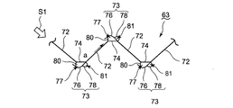
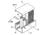
- FIG. 23 is a perspective view showing a conventional chevron vane type moisture separator.
- a number of corrugated plates 63 are mounted between the upper frame 61 and the lower frame 62.
- the corrugated plate 63 has a zigzag-shaped cross section in which peaks and valleys are alternately arranged, and a pocket 76 is provided on each flat portion 74.
- the wet steam S1 flows from the direction of the arrow into the moisture separator 60, and the moisture contained in the wet steam S1 adheres to the surface of the corrugated plate 63.
- the moisture flowing along the surface of the corrugated plate 63 in the flow direction of the wet steam S1 is received by the pocket 76 and is retained inside the pocket 76.
- the retained moisture flows downward along the surface of the corrugated plate 63 and flows down to the groove 65 provided below. Further, the moisture flying on the flow of the wet steam S1 also collides with the corrugated plate 63, is collected in the pocket portion 76 by the same action, and is separated from the wet steam S1.
- the wet steam S1 from which the moisture content has been removed by the moisture separation device 60 becomes dry steam S2, and is heated by a heating means (not shown) such as a heating pipe group provided separately.
- the size of the moisture separator is increased so that the flow velocity of the steam passing through the moisture separator does not increase as compared to the conventional case, that is, Needs to be high.
- the load for collecting moisture per wave plate increases compared to the conventional case, so the liquid film by the moisture which can be made to flow downward along the pocket portion 76 It is thought that the thickness of the water is thicker than in the prior art, the moisture is likely to be redispersed, and the moisture separation performance is lowered.
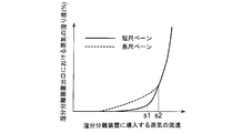
- FIG. 24 is a graph showing the relationship between the flow rate of steam introduced to the moisture separator in the conventional moisture separator and the degree of moisture of the steam at the outlet of the moisture separator.
- the horizontal axis represents the flow velocity of the steam introduced into the moisture separator
- the vertical axis represents the degree of moisture of the steam at the outlet of the moisture separator.
- the short vane shown by the solid line in FIG. 24 means the moisture separator at the height of the corrugated sheet used before the conventional moisture separator is enlarged, and the broken line in FIG. The long vane shown by these means the moisture separation apparatus in the height of the corrugated sheet when a moisture separation apparatus is enlarged.
- This limit value means the flow rate at the limit of the ability of separating the moisture by the corrugated sheet.
- An object of the present invention is to provide a moisture separator which can suppress the performance degradation of moisture separation by suppressing re-scattering of collected moisture.
- a moisture separator for separating moisture from wet steam
- a plurality of corrugated plates having a zigzag shape in which peaks and valleys are alternately arranged, and arranged at predetermined intervals to form the steam flow path of the wet steam;
- a collection plate fixed to the corrugated plate, extending toward the upstream side of the steam flow in the steam flow path, and covering a peak of the corrugated plate.
- a pocket portion is provided between the collecting plate and the corrugated plate, and is opened on the upstream side of the vapor flow;
- a drain duct portion communicating with the pocket portion and extending in the vertical direction is provided on the downstream side of the vapor flow of the pocket portion.
- the "peak part” of the corrugated sheet covered by the collection board says the part protruded toward the steam path.
- the portion projecting toward the first steam passage is referred to as the “peak portion” of the corrugated plate.
- the portion projecting toward the second steam passage is the “peak portion” of the corrugated plate.
- the term “peak portion” of the corrugated sheet means a portion projecting toward the steam passage in question.
- the moisture collected in the pocket portion flows into the drain duct portion by the steam flow and flows down in the drain duct portion, thereby reducing the amount of moisture flowing down the inside of the pocket portion and suppressing the thickness of the liquid film
- the drain duct portion is provided on the steam flow downstream side of the pocket portion, the moisture flowing down in the drain duct portion is less likely to flow back to the flow path by the steam flow flowing into the pocket portion. It is possible to suppress re-scattering of moisture. Therefore, even if the height of the corrugated sheet is increased, it is possible to suppress the performance degradation of moisture separation due to re-scattering of moisture.
- the collection plate is fixed to the corrugated plate at the downstream side of the vapor flow with respect to the peak portion of the corrugated plate, In the space formed between the collecting plate and the corrugated plate, the region on the upstream side of the vapor flow is the pocket portion, and the region on the downstream side of the vapor flow is the drain duct portion It is also good.
- a drain duct portion is formed between the end of the collecting plate and the corrugated plate.
- the drain duct portion is provided at a position behind the peak portion, and therefore the moisture flowing down the drain duct portion is less likely to flow back to the flow path. For this reason, re-scattering of the moisture in the drain duct portion can be effectively suppressed.
- the collection plate is such that the relationship between the length D from the peak to the fixed position of the collection plate and the length L from the peak to the valley of the corrugated plate satisfies 0 ⁇ D / L ⁇ 0.5. Can be prevented to prevent the collection plate from peeling off the corrugated plate by suppressing the flow of steam flowing into the drain duct portion.
- the drain plate further includes a drain plate provided between the collecting plate and the corrugated plate and guiding moisture collected in the pocket portion to the drain duct portion.
- the drain plate may be provided horizontally or inclined downward toward the downstream side of the steam flow.
- the drain plate is provided in the pocket portion, the moisture collected in the pocket portion above the drain plate flows down the inside of the pocket portion and flows into the drain duct portion through the drain plate. Therefore, the moisture trapped in the pocket does not flow down the pocket below the drain plate, and the thickness of the liquid film can be suppressed by suppressing the amount of moisture flowing down the pocket. Furthermore, by providing the drain plate horizontally or tilting downward toward the vapor flow downstream side, it is possible to prevent the moisture of the drain plate from flowing backward and flowing out from the pocket to the flow path.
- a plurality of the drain plates may be provided in the height direction of the pocket portion. As described above, since the plurality of drain plates are provided in the pocket portion, it is possible to prevent re-scattering of moisture by suppressing the thickness of the liquid film in the pocket portion even when the corrugated plate is made high.
- it further comprises a duct plate attached to the outer surface of the collecting plate and extending in the vertical direction, A space formed between the collecting plate and the corrugated plate is the pocket portion, and a space formed between the duct plate and the collecting plate is the drain duct portion.
- the drain duct portion may be in communication with the pocket portion through a drain hole penetrating the collection plate.
- the moisture collected in the pocket portion above the drain plate flows down the pocket portion, all over the drain plate.
- the moisture trapped in the pocket does not flow down the pocket below the drain plate, and the amount of moisture flowing down the pocket is suppressed to reduce the thickness of the liquid film. Can be suppressed.
- the moisture which flowed in in the drain duct part does not re-scatter, since the collection board is provided, moisture separation performance can be improved.
- the drain plate further includes a drain plate provided between the collecting plate and the corrugated plate and guiding moisture collected in the pocket portion to the drain duct portion through the drain hole.
- the drain plate may be provided horizontally or inclined downward toward the downstream side of the steam flow.
- the drain plate is provided in the pocket portion, the moisture collected in the pocket portion above the drain plate flows down the inside of the pocket portion and flows into the drain duct portion through the drain plate. Therefore, the moisture trapped in the pocket does not flow down the pocket below the drain plate, and the thickness of the liquid film can be suppressed by suppressing the amount of moisture flowing down the pocket. Furthermore, by providing the drain plate horizontally or tilting downward toward the vapor flow downstream side, it is possible to prevent the moisture of the drain plate from flowing backward and flowing out from the pocket to the flow path.
- a plurality of the drain plates are provided in the height direction of the pocket portion, The plurality of drain holes may be provided such that the upper surface of each drain plate is in communication with the drain duct portion.
- the plurality of drain plates are provided in the pocket portion, it is possible to prevent re-scattering of moisture by suppressing the thickness of the liquid film in the pocket portion even when the corrugated plate is made high.
- the plurality of drain plates may be provided to equally divide the pocket portion in the height direction.
- the plurality of drain plates are provided so as to equally divide the pocket portion in the height direction, the amount of moisture collected between the drain plates can be made substantially uniform, and the height It is possible to prevent unevenness in the performance of moisture separation depending on the position.
- a backflow prevention member may be further provided, which is provided in the pocket and prevents backflow of moisture from the pocket toward the steam flow path.
- the backflow prevention member in the pocket portion, it is possible to prevent the moisture collected in the pocket portion and the drain duct portion from flowing back to the flow path.
- the present invention even if the height of the corrugated sheet is increased, the increase in thickness of the liquid film due to the moisture collected by the corrugated sheet is suppressed, and re-scattering of the moisture collected by the corrugated sheet Thus, it is possible to provide a moisture separator capable of suppressing the performance degradation of moisture separation by suppressing the above.
- FIG. 1 It is the side view which represented the axial center part of the moisture separation heater in an Example by the partial cross section. It is an AA line cross section arrow line view in FIG. It is an upper surface figure showing a part of wave board concerning a first embodiment of the present invention. It is a side view showing a part of wave board concerning a first embodiment of the present invention. It is a perspective view showing a corrugated sheet concerning this embodiment. It is a figure which shows the other Example of the corrugated sheet which concerns on this embodiment. It is a perspective view showing a corrugated sheet concerning a second embodiment of the present invention. It is a top view which shows the corrugated sheet which concerns on 2nd embodiment of this invention. It is a BB arrow line view of FIG.
- FIG. 1 It is a perspective view showing a corrugated sheet in a third embodiment of the present invention. It is a top view which shows the corrugated sheet in 3rd embodiment of this invention. It is a figure which shows the other Example of the backflow prevention member which concerns on this embodiment. It is a figure which shows the other Example of the backflow prevention member which concerns on this embodiment. It is a perspective view which shows the corrugated sheet in 4th embodiment of this invention. It is a top view which shows the corrugated sheet in 4th embodiment of this invention. It is a CC arrow line view of FIG. It is a figure which shows the other Example of the partition wall which concerns on this embodiment. It is a top view which shows the corrugated sheet in 5th embodiment of this invention.
- FIG. 1 is a side view partially showing the axial center portion of the moisture separating heater according to this embodiment
- FIG. 2 is a sectional view taken along line AA in FIG.
- the moisture separation heater 1 is composed of left and right end plates 2 and a cylindrical body plate 4 at the center.
- a partition plate 3 is provided between the body plate 4 and the end plate 2.
- a steam receiving chamber 6 is formed in an axial central portion excluding an upper portion in the shell plate 4, and a steam receiving port 8 is formed in the steam receiving chamber 6.
- a manifold chamber 10 communicating with the steam receiving chamber 6 is formed on the radially outer side near the axial both ends in the body plate 4 and on the upper side excluding the upper portion.
- a distribution plate 12 is disposed at the lower portion of the manifold chamber 10.
- a moisture separation chamber 14 is formed below the manifold chamber 10. Inside the moisture separation chamber 14, a chevron vane type moisture separation device 16 according to the present invention is provided.
- a heating chamber communicating with the moisture separating chamber 14 in the radially inner side near the axial both ends in the body plate 4, that is, in the region surrounded by the manifold chamber 10 and the moisture separating chamber 14. 36 are formed.
- the first stage pipe group 18 is disposed on the lower side in the heating chamber 36 so that the pipe end is directed to the axial end side of the shell 4.
- the second stage pipe group 20 is disposed above the first stage pipe group in the heating chamber 36 so that the pipe end is directed to the axial end side of the shell 4.
- a first-stage heater steam chamber 22 whose inside is divided into a distribution chamber 22 a and a recovery chamber 22 b is provided on the lower side in the radially inward direction on the both axial end sides in the trunk plate 4.
- a second stage heater steam chamber 24 is provided on the radially inward upper side on both axial end sides in the trunk plate 4 and the inside thereof is divided into a distribution chamber 24a and a recovery chamber 24b.
- the heating steams 23, 25 are supplied to the distribution chambers 22a, 24a of the heater steam chambers 22, 24, and the steams 23, 25 are discharged as condensation drains in the recovery chambers 22b, 24b. Is configured.
- One pipe end of the first stage pipe group 18 is connected to the distribution chamber 22a, and the other pipe end of the first stage pipe group 18 is connected to the collection chamber 22b.
- one pipe end of the second stage pipe group 20 is connected to the distribution chamber 24a, and the other pipe end of the second stage pipe group 20 is connected to the collection chamber 24b.
- a recovery manifold chamber 26 communicating with the heating chamber 36 is formed continuously in the axial direction of the shell 4 at an upper portion in the shell 4.
- a plurality of steam delivery ports 28 communicating with the recovery manifold chamber 26 and delivering steam to an external low pressure steam turbine (not shown) are provided in the upper portion of the body plate 4.
- the steam S flowing into the heating chamber 36 comes in contact with the first stage pipe group 18 and is heated by the heating steam 23 flowing in the first stage pipe group 18. , And is further heated by the steam 25 for heating flowing in the second stage pipe group 20, and then flows into the collection manifold chamber 26.
- the steam S flowing into the recovery manifold chamber 26 flows in the recovery manifold chamber 26, is delivered from the steam delivery port 28, and is delivered to a low pressure steam turbine as a downstream device.
- the chevron vane type moisture separator 16 according to the present invention used in the moisture separator / heater 1 configured and operated as described above will be described.
- FIG.3 and FIG.4 is the top view and side view which each show a part of wave board concerning 1st embodiment of this invention.
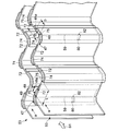
- FIG. 5 is a perspective view of the corrugated sheet according to the present embodiment.
- the wave plate 63 has a slope 72 (a portion between a peak projecting toward the steam passage and a valley recessed with respect to the steam passage) 72 and a flat surface.
- a corrugated plate 63 main body having a flat portion 74 formed in the shape of a protrusion, and a projecting member 73 for moisture collection formed so as to cover the flat portion 74 and having an opening toward the wet steam flow S1. And have.
- the projecting member 73 has a collecting plate 76 that protrudes from the inclined portion 72 on the downstream side of the flat portion 74 toward the upstream side so as to cover the flat portion (peak portion) 74.
- the base end of the collection plate 76 is fixed to the inclined portion 72 by welding, for example.
- the collecting plate 76 is curved from the proximal end toward the distal end.
- the collecting plate 76 forms a pocket 77 between the collecting plate 76 and the flat portion 74.
- the depth of the pocket portion 77 and the width of the pocket portion 77 are formed larger than the width of the wet steam flow inlet opening of the collection plate 76.
- the wet steam S ⁇ b> 1 flowing along the surface of the corrugated plate 63 flows into the pocket portion 77.
- the projecting member 73 has a duct plate 78 which is in contact with the collecting plate 76 on the downstream side in the flow direction of the wet steam S1 of the projecting member 73 and extends in the vertical direction.
- the duct plate 78 has an arc-shaped cross section, and both ends of the arc are fixed to the collecting plate 76, respectively.
- a drain duct portion 81 is formed between the collection plate 76 and the duct plate 78 by the duct plate 78.
- the drain duct portion 81 and the pocket portion 77 are separated by a collection plate 76.
- a drain plate 80 is provided which divides the inside of the pocket 77 in the vertical direction.
- the drain plate 80 is inclined downward toward the downstream side in the flow direction of the wet steam S1.
- a drain hole 82 communicating the upper surface of the drain plate 80 with the inside of the drain duct portion 81 is located above the drain plate 80 around the connection portion between the plane passing through the drain plate 80 and the collecting plate 76. It is provided. That is, the drain hole 82 communicates the upper surface of the lowermost inclined portion of the drain plate 80 with the inside of the drain duct portion 81.
- the moisture collected as a liquid film in the pocket 77 flows down the pocket 77 by gravity.
- the moisture collected in the pocket 77 below the drain plate 80 flows down to the lowermost portion of the pocket 77 and flows down to the groove 65 (see FIG. 23) provided below and collected.
- the moisture collected in the pocket 77 above the drain plate 80 flows down the pocket 77 and reaches the drain plate 80, the flow direction is changed by the drain plate 80, and By the inclination of the plate 80 and being pushed by the wet steam S1, it flows on the drain plate 80 downward in the inclination direction.
- the moisture that flows downward on the drain plate 80 slopes downward and reaches the drain hole 82 and enters the drain duct portion 81 in the duct plate 78 from the drain hole 82 and flows down the drain duct portion 81 to the lowermost portion and provided downward It flows down to the recessed groove 65 and is recovered.
- the moisture collected in the pocket 77 above the drain plate 80 passes over the drain plate 80 and flows into the drain duct 81, and this drain duct In order to flow down in the portion 81, it does not flow down in the pocket portion 77 below the drain plate 80. Therefore, the amount of moisture flowing down the inside of the pocket 77 can be suppressed to suppress the thickness of the liquid film, and re-scattering of the moisture collected by the corrugated plate 63 can be suppressed. Further, since the pocket portion 77 and the drain duct portion 81 are separated by the collection plate 76, it is possible to suppress re-scattering of the moisture that has flowed into the drain duct portion 81. Therefore, even if the height of the corrugated plate 63 is increased, it is possible to suppress the performance reduction of the moisture separation due to the re-scattering of the moisture.
- drain plate 80 only one drain plate 80 and one drain hole 82 are provided in one pocket portion 77.
- Drain plate 80 may be provided. Thereby, even when the wave plate 63 is further raised, the thickness of the liquid film in the pocket 77 can be suppressed. In that case, it is necessary to provide the same number of drain holes 82 as the drain plates 80 so as to communicate the upper surfaces of the plurality of drain plates 80 with the inside of the drain duct portion 81.
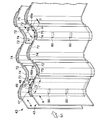
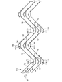
- FIGS. 7 and 8 are a perspective view and a top view showing a corrugated sheet according to a second embodiment of the present invention, respectively.
- FIG. 9 is a view taken along the line B--B in FIG.
- the wave plate 43 of the present embodiment includes the upstream end portion of the inclined portion 72 located downstream of the flat portion (peak portion protruding toward the steam passage) 74 and the flat portion
- the collecting plate 49 is formed to cover the portion 74 and has an opening toward the wet steam flow S1.
- the base end of the collection plate 49 is fixed to the inclined portion 72.
- the collection plate 49 has a plurality of bent portions from the proximal end toward the distal end side, and is formed to conform to the shape of the main body of the corrugated plate 43 as a whole.
- the first bending portion is bent in a direction away from the main body of the wave plate 43 from the base end portion toward the distal end side, and the first bending portion is separated along the inclined portion 72 when separated from the main body of the wave plate 43 by a predetermined distance. Bend at the second bending portion, and bend at the third bending portion along the flat portion (peak portion) 74 on the upstream side with respect to the second bending portion, and further along the inclined portion 72 on the upstream side Is bent at the fourth bend.
- the collecting plate 49 is adjacent to the pocket portion 47, into which the wet steam S1 flowing along the surface of the corrugated plate 43 flows, and the wet steam flow side of the pocket portion 47, and extends to near the central portion of the inclined portion 72.
- the drain duct portion 48 is formed.
- the length D from the boundary position 75 between the flat portion (peak portion) 74 and the inclined portion 72 on the downstream side to the wet steam flow downstream end 48 a of the drain duct portion 48 that is, the fixing position of the collecting plate 49
- the relationship between the slope portion (portion between the peak portion projecting toward the steam passage and the valley portion recessed toward the steam passage) 72 is expressed by the following equation (1).
- the present invention is not limited thereto.
- the drain duct portion 48 such that the length D from the boundary position 75 to the wet steam flow downstream end 48 a of the drain duct portion 48 and the length L of the inclined portion 72 satisfy the relationship of 0 ⁇ D / L ⁇ 0.5 If you
- a plurality of drain plates 80 are provided which divide the inside of the pocket portion 47 in the vertical direction at equal intervals.
- Each drain plate 80 is inclined downward toward the downstream side in the flow direction of the wet steam S1.
- the drain plate 80 is provided to divide the inside of the pocket portion 47 in the vertical direction at equal intervals, but the present invention is not limited to this.
- the wet steam S1 when the wet steam flow S1 flows between the corrugated plates 43 in the direction of the arrow a shown in FIGS. 7 and 8, the wet steam S1 is generated as in the first embodiment.
- the moisture contained is in the form of droplets and enters the pocket 47 from the inlet opening of the collecting plate 49 to form a liquid film.
- part of the moisture in the pocket 47 is pushed by the wet steam S1 flowing into the pocket 47 and enters the drain duct 48 to form a liquid film.
- most of the wet steam flow S1 passing through the flow path advances outside the collection plate 49 and flows downstream.
- the moisture collected as a liquid film in the drain duct portion 48 and the pocket portion 47 flows down in the drain duct portion 48 and the pocket portion 47, respectively, by gravity.
- the moisture in the drain duct portion 48 is pushed down by the wet steam flow S1 to move downward while moving deep toward the downstream side. And it flows down to the groove
- the moisture collected above the drain plates 80 in the pocket 47 passes over the drain plates 80 and flows down the drain duct portion 48.
- the moisture that flows down in the drain duct portion 48 flows down deep in the drain duct portion 48, so that it is possible to suppress that the moisture re-scatters. Therefore, even if the height of the corrugated plate 43 is increased, it is possible to suppress the performance degradation of the moisture separation due to the re-scattering of the moisture.
- the collection board 49 is comprised from the collection board 49 of 1 sheet, the effort for attachment to the corrugated sheet 43 main body is not taken, and it can manufacture it at low cost.
- drain plates 80 are provided in one pocket portion 47, only one drain plate 80 may be provided. In that case, it is desirable to provide the drain plate 80 near the center of the height of the corrugated plate 43.
- the wave plate 54 of the present embodiment includes a collecting plate 49 as in the second embodiment, and between the collecting plate 49 and the main body of the wave plate 54, A pocket 47 and a drain duct 48 are formed. Further, in the pocket portion 47, a plurality of drain plates 80 are provided.
- the flat portion 74 in the pocket portion 47 according to the present embodiment is provided with a plurality of backflow prevention members 52 in the vertical direction.
- the backflow prevention member 52 has a substantially U-shaped cross section, and is fixed to the flat portion 74 such that the U-shaped opening faces the drain duct portion 48 side.
- the backflow prevention member 52 is provided above the uppermost drain plate 80, between adjacent drain plates 80, and below the lowermost drain plate 80.
- the backflow preventing member 52 is present in the pocket portion 47, so the moisture is prevented from flowing back It enters into the recess 52 a of the member 52. Then, it is collected in the recess 52 a of the backflow prevention member 52.
- each drain plate 80 When the moisture collected in the recess 52a flows down in the recess 52a by gravity and reaches the top of each drain plate 80, the moisture flows downward on each drain plate 80 and enters the drain duct portion 48, and drain duct It flows down to the lowermost part in the portion 48, flows down to the groove 65, and is collected.
- the moisture flowing down the drain duct portion 48 can be prevented from flowing back to the flow path, so collection by the corrugated plate 54 It is possible to suppress the re-dispersion of wet moisture.
- the backflow prevention member 52 having a substantially U-shaped cross section is used has been described, but the present invention is not limited to this shape.
- a backflow prevention member having an L-shaped cross section, or a backflow prevention member having a substantially V-shaped cross section as shown in FIG. 13 may be used.
- the point is that any shape that can prevent the moisture flowing down the drain duct portion 48 from flowing out to the outside of the collecting plate 49 may be used.
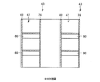
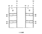
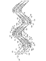
- FIGS. 14 and 15 are a perspective view and a top view showing a corrugated sheet in a fourth embodiment of the present invention, respectively.
- FIG. 16 is a view taken along the line CC in FIG.
- the wave plate 53 of the present embodiment includes a collection plate 49 as in the second and third embodiments, and is provided between the collection plate 49 and the corrugated plate 53 main body.
- a pocket 47 and a drain duct 48 are formed. Further, in the pocket portion 47, a plurality of drain plates 80 are provided.
- a partition wall 59 that partitions the pocket 47 and the drain duct 48 is provided between the collecting plate 49 and the main body of the corrugated plate 53 according to the present embodiment.
- the partition wall 59 has the same height as the wave plate 53, and is provided along the vertical direction of the wave plate 53.
- the end of the drain plate 80 is connected to the side surface of the partition wall 59.
- a drain hole 82 communicating the upper surface of the drain plate 80 and the inside of the drain duct portion 48 is provided in the partition wall 59 above the drain plate 80.
- the moisture collected in the pocket 47 flows down the pocket 47 by gravity.
- the moisture collected in the pocket portion 47 below the drain plate 80 provided at the lowermost stage flows down to the lowermost portion as it is, and flows down to the groove 65 provided below and is collected.
- the drains are drained as in the first embodiment. It flows downward on the plate 80 in the direction of inclination and reaches the drain hole 82 and enters the drain duct portion 48 through the drain hole 82 and flows down the drain duct portion 48 to the lowermost portion and flows down into the groove 65 provided below. Be collected.
- the moisture collected in the pocket portion 47 above the drain plates 80 passes over the drain plate 80 and flows into the drain duct portion 48 to be drain ducts. In order to flow down in the portion 48, it does not flow down in the pocket portion 47 below the drain plates 80. Therefore, the amount of moisture flowing down the pocket portion 47 can be suppressed to suppress the thickness of the liquid film, and re-scattering of the moisture collected by the corrugated plate 53 can be suppressed. Further, since the pocket portion 47 and the drain duct portion 48 are separated by the partition wall 59, it is possible to suppress the moisture that has flowed into the drain duct portion 48 from flowing back into the flow path through the pocket portion 47 and re-scattering can do. Therefore, even if the height of the corrugated plate 53 is increased, it is possible to suppress the performance decrease of the moisture separation due to the re-scattering of the moisture.
- the partition wall 59 having the same height as the wave plate 53 is provided, but as shown in FIG. 17, the partition wall 59 may be provided shorter than the height of the wave plate 53. In that case, according to the height of the partition wall 59, the number of drain plates 80 and an attachment position are adjusted suitably.
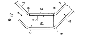
- FIG. 18 is a top view showing a corrugated sheet in a fifth embodiment of the present invention.
- the corrugated plate 103 of this embodiment is formed so as to cover a flat portion (a peak portion protruding toward the steam passage) 74 and is a collection having an opening portion toward the wet steam flow S1.
- a plate 109, a duct plate 101 circumscribing the collection plate 109, and a drain plate 80 are provided.
- the collection plate 109 is provided to cover the flat portion 74 from the inclined portion 72 on the downstream side of the flat portion 74 toward the upstream side. Further, the proximal end portion of the collection plate 109 is fixed to the inclined portion 72. Then, the collection plate 109 is bent along the flat portion 74 at the first bent portion as it goes from the base end portion to the distal end side, and further upstream of the flat portion 74 on the upstream side of the first bent portion. It is bent at the second bending portion so as to be along the inclined portion 72 located on the side.
- the collecting plate 109 forms a pocket portion 107 into which the wet steam S1 flowing along the surface of the corrugated plate 103 flows.
- the duct plate 101 is provided so as to circumscribe the collecting plate 109 on the downstream side in the flow direction of the wet steam S1 and extend in the vertical direction.
- the base end of the duct plate 101 is fixed to the downstream side of the collecting plate 109.
- the duct plate 101 is bent in a direction away from the wave plate 103 at the first bending portion as it goes from the base end to the distal end side, and along the inclined portion 72 on the upstream side of the first bending portion. It is bent at the second bent portion, and further bent at the third bent portion along the flat portion 74 on the upstream side of the second bent portion, and the tip portion is fixed to the collecting plate 109.
- the height of the duct plate 101 is half of the height of the corrugated plate 103.
- a drain duct portion 108 is formed between the duct plate 101 and the collecting plate 109 by the duct plate 101.
- the drain duct portion 108 has a length D from the boundary position 75 between the flat portion 74 and the slope portion 72 to the wet steam flow downstream end 108 a of the drain duct portion 108 and the length of the slope portion 72 as in the second embodiment.
- the relationship with L satisfies the above equation (1).
- the drain duct 108 and the pocket 107 are separated by a collecting plate 109.
- a drain hole 82 is provided in the collecting plate 109, and the upper surface of the lowermost inclined portion of the drain plate 80 provided in the pocket portion 107 communicates with the inside of the drain duct portion 108 through the drain hole 82.
- the moisture collected in the pocket portion 107 above the drain plate 80 passes through the drain plate 80 and flows down the drain duct portion 108 as in the above-described embodiments. Therefore, it does not flow down the inside of the pocket portion 107 below the drain plate 80. Therefore, the amount of moisture flowing down the pocket portion 107 can be suppressed to suppress the thickness of the liquid film, and the recapture of the moisture collected by the corrugated plate 103 can be suppressed. Moreover, since the pocket part 107 and the drain duct part 108 are divided by the collection board 109, it can suppress that the moisture which flowed in in the drain duct part 108 re-scatters. Therefore, even if the height of the corrugated plate 103 is increased, it is possible to suppress the performance degradation of the moisture separation due to the re-scattering of the moisture.
- FIG. 19 is a top view showing a conventional wave plate.
- the base end portion of the collecting plate 110 of the conventional corrugated plate 111 is fixed to the inclined portion 72, and the tip end side protrudes toward the upstream side of the wet steam flow S1. Further, the collecting plate 110 is bent so that the tip thereof approaches the main body of the corrugated plate 111.
- a pocket 112 is formed between the collecting plate 110 and the main body of the corrugated plate 111 by the collecting plate 110.
- FIG. 20 and FIG. 21 are contour diagrams showing a flow velocity distribution state of a part between the wave plates in the conventional example and the embodiment, respectively.
- an area with a low flow velocity that is, a separation area of the flow (portion in dotted frame in the drawing) is generated in the flow path along the collecting plate 110.
- the separation area of this flow extends to the downstream of the position where the collecting plate 110 is provided.
- the drain plate 80 is inclined downward toward the downstream side in the flow direction of the wet steam S1.
- the present invention is not limited to this, and the drain plate 80 may be provided horizontally. Even if the drain plate 80 is provided horizontally, the moisture that has reached the drain plate 80 can flow downstream by being pushed by the wet steam S1.
- the present invention can be applied to other chevron vane type moisture separators. It is.
- FIG. 22 is a block diagram of a wet electrostatic precipitator to which the moisture separator of the present invention is applied.
- a wet electrostatic precipitator is used, for example, to remove the moisture of the fuel gas in a fuel gas / gas turbine combined cycle system.
- the fuel gas enters the inlet duct 91 from the direction of the arrow in the figure, passes through the multi-porous grid window 92 and passes through the discharge electrode 93 and the dust collection electrode 94 The dust is discharged to the outlet duct 95.
- the mist is removed by a chevron vane type moisture separator 96 attached to the outlet duct 95.
- the same moisture separation device 16 as described above with reference to FIGS. 3 to 18 and 23 can be applied to the moisture separation device 96 applied to the wet electrostatic precipitator 90 as described above. .
- the present invention even if the height of the corrugated sheet is increased, the thickness of the liquid film due to the moisture collected by the corrugated sheet is prevented from becoming thick, and the re-scattering of the moist collected by the corrugated sheet is suppressed By doing this, it is possible to use as a chevron vane type moisture separator capable of suppressing the performance degradation of moisture separation.
Landscapes
- Engineering & Computer Science (AREA)
- Physics & Mathematics (AREA)
- General Engineering & Computer Science (AREA)
- Thermal Sciences (AREA)
- Mechanical Engineering (AREA)
- Chemical & Material Sciences (AREA)
- High Energy & Nuclear Physics (AREA)
- Chemical Kinetics & Catalysis (AREA)
- Analytical Chemistry (AREA)
- General Chemical & Material Sciences (AREA)
- Oil, Petroleum & Natural Gas (AREA)
- Plasma & Fusion (AREA)
- Separating Particles In Gases By Inertia (AREA)
Priority Applications (3)
| Application Number | Priority Date | Filing Date | Title |
|---|---|---|---|
| EP11842598.2A EP2623177B1 (en) | 2010-11-26 | 2011-11-11 | Moisture separation device |
| CN201180051338.4A CN103180024B (zh) | 2010-11-26 | 2011-11-11 | 水分分离装置 |
| KR1020137011073A KR101596106B1 (ko) | 2010-11-26 | 2011-11-11 | 습분 분리 장치 |
Applications Claiming Priority (4)
| Application Number | Priority Date | Filing Date | Title |
|---|---|---|---|
| JP2010-263689 | 2010-11-26 | ||
| JP2010263689 | 2010-11-26 | ||
| JP2011-164557 | 2011-07-27 | ||
| JP2011164557A JP5721579B2 (ja) | 2010-11-26 | 2011-07-27 | 湿分分離装置 |
Publications (1)
| Publication Number | Publication Date |
|---|---|
| WO2012070411A1 true WO2012070411A1 (ja) | 2012-05-31 |
Family
ID=46125710
Family Applications (1)
| Application Number | Title | Priority Date | Filing Date |
|---|---|---|---|
| PCT/JP2011/076069 Ceased WO2012070411A1 (ja) | 2010-11-26 | 2011-11-11 | 湿分分離装置 |
Country Status (6)
| Country | Link |
|---|---|
| US (1) | US8790433B2 (https=) |
| EP (1) | EP2623177B1 (https=) |
| JP (1) | JP5721579B2 (https=) |
| KR (1) | KR101596106B1 (https=) |
| CN (1) | CN103180024B (https=) |
| WO (1) | WO2012070411A1 (https=) |
Cited By (2)
| Publication number | Priority date | Publication date | Assignee | Title |
|---|---|---|---|---|
| CN104226022A (zh) * | 2013-06-06 | 2014-12-24 | 阿尔斯通技术有限公司 | 水分分离器构造 |
| WO2025001553A1 (zh) * | 2023-06-26 | 2025-01-02 | 上海康恒环境股份有限公司 | 一种汽轮机低压湿蒸汽中间机外除湿设备 |
Families Citing this family (21)
| Publication number | Priority date | Publication date | Assignee | Title |
|---|---|---|---|---|
| JP4848333B2 (ja) * | 2007-09-07 | 2011-12-28 | 三菱重工業株式会社 | 湿分分離加熱器 |
| DE102012014309B4 (de) * | 2012-07-19 | 2022-06-30 | Airbus Operations Gmbh | Partikelabscheider für eine Luftleitung, Luftverteilungssystem und Verwendung eines Partikelabscheiders |
| CN103861389A (zh) * | 2012-12-14 | 2014-06-18 | 中国核动力研究设计院 | 一种应用于核电站蒸汽发生器中汽水分离器的分流器 |
| CN103372349B (zh) * | 2013-05-30 | 2015-07-15 | 浙江天地环保工程有限公司 | 脱硫塔出口烟道除雾装置 |
| CN105327552B (zh) * | 2014-06-25 | 2017-09-19 | 普尔利斯(中国)环保分离设备制造有限公司 | 用于从气体分离液体的双袋型叶片式分离器 |
| KR101945410B1 (ko) * | 2014-07-25 | 2019-02-07 | 한화파워시스템 주식회사 | 기수분리기 |
| US10553322B2 (en) * | 2015-09-28 | 2020-02-04 | Ge-Hitachi Nuclear Energy Americas Llc | Modular fluid flow distribution system in which differently shaped plates can be rearranged to different positions |
| CN105423272B (zh) * | 2015-12-24 | 2018-02-13 | 哈尔滨锅炉厂有限责任公司 | 高效汽水分离装置及分离方法 |
| CN105537873B (zh) * | 2016-01-06 | 2019-01-11 | 上海发电设备成套设计研究院 | 一种疏水钩波纹板成形制造方法 |
| CN105749628B (zh) * | 2016-04-13 | 2018-01-19 | 上海发电设备成套设计研究院 | 一种汽水分离波纹板及分离器 |
| CN105749627A (zh) * | 2016-04-13 | 2016-07-13 | 上海发电设备成套设计研究院 | 一种不等距波纹板汽水分离器 |
| CN106178747B (zh) * | 2016-08-20 | 2018-11-06 | 浙江众立机械制造有限公司 | 除尘设备 |
| JP7144265B2 (ja) * | 2018-10-02 | 2022-09-29 | 三菱重工業株式会社 | 湿分分離器、及び蒸気タービンプラント |
| JP7300639B2 (ja) * | 2019-03-25 | 2023-06-30 | パナソニックIpマネジメント株式会社 | 熱交換ユニット及び吸収式冷凍機 |
| KR102103835B1 (ko) * | 2019-10-16 | 2020-04-23 | 주식회사 에코이엔지 | 먼지집진체 |
| KR102340656B1 (ko) * | 2019-12-10 | 2021-12-17 | 두산중공업 주식회사 | 쉐브론 베인 및 이를 포함하는 습분분리기 |
| WO2021207949A1 (zh) * | 2020-04-14 | 2021-10-21 | 深圳市迪尔安科技有限公司 | 一种厨房抽油烟机的油烟分离器 |
| JP7594982B2 (ja) | 2021-07-28 | 2024-12-05 | 日立Geニュークリア・エナジー株式会社 | 蒸気乾燥器 |
| US11828230B2 (en) * | 2021-10-04 | 2023-11-28 | General Electric Company | System and method for mitigating particulate intrusion to an air intake system of a gas turbine system with intrusion protective coatings tailored to locale of operation |
| CN114100254A (zh) * | 2021-11-26 | 2022-03-01 | 中国核动力研究设计院 | 一种一体化波形板及干燥器 |
| CN114704339B (zh) * | 2022-03-09 | 2023-09-08 | 中国船舶重工集团公司第七0三研究所 | 一种铍尖式除湿装置 |
Citations (9)
| Publication number | Priority date | Publication date | Assignee | Title |
|---|---|---|---|---|
| JPS50128873A (https=) * | 1974-03-29 | 1975-10-11 | ||
| JPS5145376A (ja) * | 1974-10-16 | 1976-04-17 | Hitachi Ltd | Shitsubunbunrisochi |
| JPS5439271A (en) * | 1977-06-11 | 1979-03-26 | Regehr Ulrich | Liquidddrop separator |
| JPS59130514A (ja) * | 1982-10-12 | 1984-07-27 | ウルリツヒ,レゲ−ル | ガス流から液滴又は微粒子状固形物を分離する装置 |
| JPS60190214A (ja) * | 1984-03-13 | 1985-09-27 | Toshiba Corp | 湿分分離装置 |
| JPS62279818A (ja) * | 1986-05-14 | 1987-12-04 | フラマト−ム | 分離装置 |
| JPH08332331A (ja) * | 1995-04-11 | 1996-12-17 | Hoval Interliz Ag | 暖房・換気・冷房用の局域型空調装置 |
| JP2002311180A (ja) | 2001-04-18 | 2002-10-23 | Mitsubishi Heavy Ind Ltd | 湿分分離器 |
| JP2008194633A (ja) * | 2007-02-14 | 2008-08-28 | Mitsubishi Heavy Ind Ltd | 湿分分離装置及びその波板製造方法 |
Family Cites Families (11)
| Publication number | Priority date | Publication date | Assignee | Title |
|---|---|---|---|---|
| DE2251173C2 (de) * | 1972-10-19 | 1979-08-30 | L. & C. Steinmueller Gmbh, 5270 Gummersbach | Abscheidevorrichtung |
| JPS52130072A (en) * | 1976-04-23 | 1977-11-01 | Hitachi Ltd | Separator element of corrugated-plant type separator |
| JPS5838205B2 (ja) * | 1979-10-11 | 1983-08-22 | 株式会社日立製作所 | 気水分離装置の波板支持装置 |
| SE461318B (sv) | 1982-10-12 | 1990-02-05 | Munters Ab Carl | Anordning foer att avskilja vaetskedroppar eller finkorniga fasta aemnen ur en gasstroem |
| JPS61265489A (ja) | 1985-05-17 | 1986-11-25 | Toshiba Corp | 復水装置 |
| JPS62185306U (https=) | 1986-05-09 | 1987-11-25 | ||
| JPH05145376A (ja) * | 1991-11-15 | 1993-06-11 | Sony Corp | デイジタルフイルタ |
| JPH06222190A (ja) * | 1992-12-03 | 1994-08-12 | Hitachi Ltd | 蒸気乾燥器及び気水分離システム並びに湿分分離器 |
| JP2002126429A (ja) * | 2000-10-20 | 2002-05-08 | Mitsubishi Heavy Ind Ltd | 湿分分離器 |
| JP2003144824A (ja) * | 2001-11-06 | 2003-05-20 | Mitsubishi Heavy Ind Ltd | 湿分分離器及び蒸気発生器 |
| JP5403978B2 (ja) | 2008-09-16 | 2014-01-29 | 三菱重工業株式会社 | 復水器 |
-
2011
- 2011-07-27 JP JP2011164557A patent/JP5721579B2/ja active Active
- 2011-11-11 EP EP11842598.2A patent/EP2623177B1/en not_active Not-in-force
- 2011-11-11 WO PCT/JP2011/076069 patent/WO2012070411A1/ja not_active Ceased
- 2011-11-11 CN CN201180051338.4A patent/CN103180024B/zh not_active Expired - Fee Related
- 2011-11-11 KR KR1020137011073A patent/KR101596106B1/ko not_active Expired - Fee Related
- 2011-11-16 US US13/297,874 patent/US8790433B2/en not_active Expired - Fee Related
Patent Citations (9)
| Publication number | Priority date | Publication date | Assignee | Title |
|---|---|---|---|---|
| JPS50128873A (https=) * | 1974-03-29 | 1975-10-11 | ||
| JPS5145376A (ja) * | 1974-10-16 | 1976-04-17 | Hitachi Ltd | Shitsubunbunrisochi |
| JPS5439271A (en) * | 1977-06-11 | 1979-03-26 | Regehr Ulrich | Liquidddrop separator |
| JPS59130514A (ja) * | 1982-10-12 | 1984-07-27 | ウルリツヒ,レゲ−ル | ガス流から液滴又は微粒子状固形物を分離する装置 |
| JPS60190214A (ja) * | 1984-03-13 | 1985-09-27 | Toshiba Corp | 湿分分離装置 |
| JPS62279818A (ja) * | 1986-05-14 | 1987-12-04 | フラマト−ム | 分離装置 |
| JPH08332331A (ja) * | 1995-04-11 | 1996-12-17 | Hoval Interliz Ag | 暖房・換気・冷房用の局域型空調装置 |
| JP2002311180A (ja) | 2001-04-18 | 2002-10-23 | Mitsubishi Heavy Ind Ltd | 湿分分離器 |
| JP2008194633A (ja) * | 2007-02-14 | 2008-08-28 | Mitsubishi Heavy Ind Ltd | 湿分分離装置及びその波板製造方法 |
Non-Patent Citations (1)
| Title |
|---|
| See also references of EP2623177A4 * |
Cited By (3)
| Publication number | Priority date | Publication date | Assignee | Title |
|---|---|---|---|---|
| CN104226022A (zh) * | 2013-06-06 | 2014-12-24 | 阿尔斯通技术有限公司 | 水分分离器构造 |
| CN104226022B (zh) * | 2013-06-06 | 2016-10-05 | 通用电器技术有限公司 | 水分分离器构造 |
| WO2025001553A1 (zh) * | 2023-06-26 | 2025-01-02 | 上海康恒环境股份有限公司 | 一种汽轮机低压湿蒸汽中间机外除湿设备 |
Also Published As
| Publication number | Publication date |
|---|---|
| EP2623177B1 (en) | 2016-04-20 |
| JP2012125757A (ja) | 2012-07-05 |
| EP2623177A1 (en) | 2013-08-07 |
| US20120131891A1 (en) | 2012-05-31 |
| KR20130103543A (ko) | 2013-09-23 |
| JP5721579B2 (ja) | 2015-05-20 |
| EP2623177A4 (en) | 2014-07-02 |
| KR101596106B1 (ko) | 2016-02-19 |
| US8790433B2 (en) | 2014-07-29 |
| CN103180024A (zh) | 2013-06-26 |
| CN103180024B (zh) | 2015-01-14 |
Similar Documents
| Publication | Publication Date | Title |
|---|---|---|
| WO2012070411A1 (ja) | 湿分分離装置 | |
| CA1313626C (en) | Liquid separator | |
| CN1250319C (zh) | 除湿装置和蒸汽发生器 | |
| CN104226022B (zh) | 水分分离器构造 | |
| CN101495715A (zh) | 燃气涡轮机配置 | |
| CN101135251A (zh) | 蒸汽涡轮发动机内脱湿系统 | |
| CN108097463A (zh) | 一种节能高效电除尘器 | |
| JPS594410A (ja) | 高速水分離装置 | |
| CN111405936B (zh) | 具有冷凝物收集器的湿烟囱导向叶片 | |
| CN101375021B (zh) | 湿分分离加热器 | |
| JP4039233B2 (ja) | 蒸気乾燥器 | |
| JPS62237205A (ja) | 湿分分離再熱器 | |
| CN217247427U (zh) | 蒸汽干湿分离器 | |
| CN106133442B (zh) | 湿分分离加热器 | |
| CN210420716U (zh) | 一种透平真空风机气液分离室 | |
| CN112403209B (zh) | 一种波形板汽水分离元件 | |
| CN103118762A (zh) | 管道和用于安装于其中的冷凝物边缘薄膜采集和导出装置 | |
| US20210236974A1 (en) | Mist eliminator | |
| RU2071375C1 (ru) | Высокоскоростной сепаратор для паропроводов паровых турбин | |
| CN207521159U (zh) | 一种节能高效电除尘器 | |
| CN222597821U (zh) | 吸油烟机及包含其的厨房系统 | |
| CN211952891U (zh) | 一种厨房抽油烟机的除油装置 | |
| RU2392034C1 (ru) | Сепаратор | |
| WO2017090557A1 (ja) | 湿分分離加熱器 | |
| CN107923611A (zh) | 湿分分离器及蒸汽涡轮设备 |
Legal Events
| Date | Code | Title | Description |
|---|---|---|---|
| 121 | Ep: the epo has been informed by wipo that ep was designated in this application |
Ref document number: 11842598 Country of ref document: EP Kind code of ref document: A1 |
|
| ENP | Entry into the national phase |
Ref document number: 20137011073 Country of ref document: KR Kind code of ref document: A |
|
| WWE | Wipo information: entry into national phase |
Ref document number: 2011842598 Country of ref document: EP |
|
| NENP | Non-entry into the national phase |
Ref country code: DE |