EP2623177B1 - Moisture separation device - Google Patents
Moisture separation device Download PDFInfo
- Publication number
- EP2623177B1 EP2623177B1 EP11842598.2A EP11842598A EP2623177B1 EP 2623177 B1 EP2623177 B1 EP 2623177B1 EP 11842598 A EP11842598 A EP 11842598A EP 2623177 B1 EP2623177 B1 EP 2623177B1
- Authority
- EP
- European Patent Office
- Prior art keywords
- plate
- drain
- moisture
- section
- steam
- Prior art date
- Legal status (The legal status is an assumption and is not a legal conclusion. Google has not performed a legal analysis and makes no representation as to the accuracy of the status listed.)
- Not-in-force
Links
Images


Classifications
-
- B—PERFORMING OPERATIONS; TRANSPORTING
- B01—PHYSICAL OR CHEMICAL PROCESSES OR APPARATUS IN GENERAL
- B01D—SEPARATION
- B01D45/00—Separating dispersed particles from gases or vapours by gravity, inertia, or centrifugal forces
- B01D45/04—Separating dispersed particles from gases or vapours by gravity, inertia, or centrifugal forces by utilising inertia
- B01D45/08—Separating dispersed particles from gases or vapours by gravity, inertia, or centrifugal forces by utilising inertia by impingement against baffle separators
-
- B—PERFORMING OPERATIONS; TRANSPORTING
- B01—PHYSICAL OR CHEMICAL PROCESSES OR APPARATUS IN GENERAL
- B01D—SEPARATION
- B01D53/00—Separation of gases or vapours; Recovering vapours of volatile solvents from gases; Chemical or biological purification of waste gases, e.g. engine exhaust gases, smoke, fumes, flue gases, aerosols
- B01D53/26—Drying gases or vapours
- B01D53/265—Drying gases or vapours by refrigeration (condensation)
-
- F—MECHANICAL ENGINEERING; LIGHTING; HEATING; WEAPONS; BLASTING
- F22—STEAM GENERATION
- F22B—METHODS OF STEAM GENERATION; STEAM BOILERS
- F22B37/00—Component parts or details of steam boilers
- F22B37/02—Component parts or details of steam boilers applicable to more than one kind or type of steam boiler
- F22B37/26—Steam-separating arrangements
- F22B37/268—Steam-separating arrangements specially adapted for steam generators of nuclear power plants
-
- F—MECHANICAL ENGINEERING; LIGHTING; HEATING; WEAPONS; BLASTING
- F22—STEAM GENERATION
- F22B—METHODS OF STEAM GENERATION; STEAM BOILERS
- F22B37/00—Component parts or details of steam boilers
- F22B37/02—Component parts or details of steam boilers applicable to more than one kind or type of steam boiler
- F22B37/26—Steam-separating arrangements
- F22B37/28—Steam-separating arrangements involving reversal of direction of flow
- F22B37/286—Steam-separating arrangements involving reversal of direction of flow specially adapted for steam generators of nuclear power plants
-
- F—MECHANICAL ENGINEERING; LIGHTING; HEATING; WEAPONS; BLASTING
- F22—STEAM GENERATION
- F22B—METHODS OF STEAM GENERATION; STEAM BOILERS
- F22B37/00—Component parts or details of steam boilers
- F22B37/02—Component parts or details of steam boilers applicable to more than one kind or type of steam boiler
- F22B37/26—Steam-separating arrangements
- F22B37/30—Steam-separating arrangements using impingement against baffle separators
- F22B37/306—Steam-separating arrangements using impingement against baffle separators specially adapted for steam generators of nuclear power plants
-
- F—MECHANICAL ENGINEERING; LIGHTING; HEATING; WEAPONS; BLASTING
- F22—STEAM GENERATION
- F22G—SUPERHEATING OF STEAM
- F22G3/00—Steam superheaters characterised by constructional features; Details of component parts thereof
-
- G—PHYSICS
- G21—NUCLEAR PHYSICS; NUCLEAR ENGINEERING
- G21C—NUCLEAR REACTORS
- G21C15/00—Cooling arrangements within the pressure vessel containing the core; Selection of specific coolants
- G21C15/16—Cooling arrangements within the pressure vessel containing the core; Selection of specific coolants comprising means for separating liquid and steam
-
- Y—GENERAL TAGGING OF NEW TECHNOLOGICAL DEVELOPMENTS; GENERAL TAGGING OF CROSS-SECTIONAL TECHNOLOGIES SPANNING OVER SEVERAL SECTIONS OF THE IPC; TECHNICAL SUBJECTS COVERED BY FORMER USPC CROSS-REFERENCE ART COLLECTIONS [XRACs] AND DIGESTS
- Y02—TECHNOLOGIES OR APPLICATIONS FOR MITIGATION OR ADAPTATION AGAINST CLIMATE CHANGE
- Y02E—REDUCTION OF GREENHOUSE GAS [GHG] EMISSIONS, RELATED TO ENERGY GENERATION, TRANSMISSION OR DISTRIBUTION
- Y02E30/00—Energy generation of nuclear origin
- Y02E30/30—Nuclear fission reactors
Definitions
- the present invention relates to a moisture separator which separates moisture from steam, and is applicable to, for example, a power generation plant such as a nuclear power plant and a blast-furnace gas (BFG) fired gas turbine combined-cycle (GTCC) system.
- a power generation plant such as a nuclear power plant and a blast-furnace gas (BFG) fired gas turbine combined-cycle (GTCC) system.
- BFG blast-furnace gas
- GTCC gas turbine combined-cycle
- a moisture separator is normally used in a power generation plant such as a nuclear power plant to eliminate moisture from steam generated in a steam generator or to eliminate moisture from moist steam discharged from a high pressure turbine so as to supply dry steam toward a low pressure turbine. This suppresses erosion of the turbine blades and also improves plant efficiency.
- a chevron-vane type moisture separator is known as one of such moisture separators.
- the chevron-vane type moisture separator is, for example, disclosed in Patent Literature 1.
- FIG.23 is a perspective view of a conventional moisture separator of chevron-vane type.
- FIG.23 shows a moisture separator 60 where a plurality of corrugated plates 63 are mounted between an upper frame 61 and a lower frame 62.
- Each corrugated plate 63 has a zigzag cross-sectional shape with projections and depressions that are arranged alternately.
- Each of flat parts has a pocket section.
- Moist steam S1 enters the moisture separator 60 in a direction of an arrow and moisture contained in the moist steam S1 adheres on a surface of the corrugated plate 63. Then the moisture streaming in a flow direction of the moist steam S1 along the surface of the corrugated plate 63 is captured at the pocket section and retained in the pocket section.
- the retained moisture flows down along the surface of the corrugated plate 63 and falls down into a groove 65 provided below.
- Moisture flying along the stream of the moist steam S1 collides against the corrugated plate 63 and is captured by the pocket section in the same manner as above to be separated from the moist steam S1.
- the moist steam S1 from which the moisture is removed by the moisture separator 60, becomes dry steam S2 and is heated by a heating means (not shown) such as a group of heating tubes provided separately.
- documents JP S56 53716 A , JP 2002 126429 A , DE 195 13 201 C1 and US 2004/069243 A1 disclose various examples of conventional moisture separators.
- FIG.24 is a graph showing a relationship between a flow velocity of steam entering the moisture separator of the related art and wetness of the steam at an outlet of the moisture separator of the related art.
- the horizontal axis represents the flow velocity of the steam entering the moisture separator and the vertical axis represents the wetness of the steam at the outlet of the moisture separator.
- a shorter vane shown by a solid line indicates a moisture separator with a height of the conventional corrugated plate used prior to upsizing of the moisture separator, whereas a longer vane shown by a broken line indicates a moisture separator with a height of the corrugated plate in the case of upsizing the moisture separator.
- an object of the present invention is to provide a moisture separator that is capable of, even with an increased height of the corrugated plate, suppressing the performance drop of the moisture separation by suppressing increase in thickness of the liquid film formed by the moisture collected by the corrugated plate and by suppressing the re-entrainment of the moisture collected by the corrugated plate.
- the present invention provides a moisture separator as defined in the appended claims.
- the projection which is covered by the collecting plate herein refers to a part which projects toward the steam passage.
- the projection is a part projecting toward the first steam passage.
- the projection is a part projecting toward the second steam passage.
- the projection of the corrugated plate refers to the part projecting toward an intended steam passage.
- the moisture collected in the pocket section streams into the drain duct section by the steam flow and flows down inside the drain duct section.
- the moisture collected in the pocket section streams into the drain duct section by the steam flow and flows down inside the drain duct section.
- the drain duct section By providing the drain duct section on the downstream side of the pocket section in the direction of the steam flow, the moisture flowing down inside the drain duct is unlikely to flow back into the steam passage due to the steam flow entering the pocket section.
- the decrease in performance of moisture separation caused by the re-entrainment of the moisture can be suppressed.
- the collecting plate may be fixed to the corrugated plate on the downstream side of the projection in the direction of the steam flow.
- an upstream portion and a downstream portion in the direction of the steam flow may function as the pocket section and the drain duct section, respectively.
- the drain duct section is formed between an end part of the collecting plate and the corrugated plate.
- the drain duct section is arranged behind the projection and thus, the moisture flowing down inside the drain duct section is unlikely to flow back to the steam passage. Therefore, it is possible to effectively suppress the re-entrainment of the moisture collected in the drain duct section.
- the corrugated plate may be arranged to satisfy a relationship of 0 ⁇ D/L ⁇ 0.5, where D is a length from the projection to a position to which the collecting plate is fixed, and L is a length between the projection and the depression of the corrugated plate.
- the collecting plate is fixed to the corrugated plate to satisfy the relationship of 0 ⁇ D/L ⁇ 0.5, where D is the length from the projection to the position to which the collecting plate is fixed, and L is the length between the projection and the depression of the corrugated plate, so as to control the steam flow entering the drain duct section.
- the above moisture separator may further include a drain plate which is provided between the collecting plate and the corrugated plate to direct the moisture collected in the pocket section to the drain duct section.
- the drain plate may be arranged horizontally or downwardly-inclined toward the downstream side in the direction of the steam flow.
- the moisture collected in the pocket section above the drain plate flows down inside the pocket section and moves over the drain plate in its entirety to enter the drain duct section. Therefore, the moisture collected in the pocket section does not flow down inside the pocket section below the drain plate and thus, it is possible to suppress thickness of the liquid film by reducing the amount of moisture flowing down inside the pocket section.
- a plurality of the drain plates may be provided in a height direction of the pocket section.
- the above moisture separator may further include a duct plate which is provided on an outer surface of the collecting plate and extends vertically.
- the pocket section may be a space formed between the collecting plate and the corrugated plate and the drain duct section may be a space formed between the duct plate and the collecting plate.
- the drain duct section may be in communication with the pocket section through a drain through-hole which passes through the collecting plate.
- the collecting plate By arranging the collecting plate with the drain through-hole between the pocket section and the drain duct section, the moisture collected in the pocket section above the drain plate flows down inside the pocket section and moves over the drain plate in its entirety into the drain duct section through the drain through-hole.
- the moisture collected in the pocket section does not flows down inside the pocket section below the drain plate and thus, it is possible to suppress thickness of the liquid film by reducing the amount of the moisture flowing down the pocket section.
- the above moisture separator may also include a drain plate which is provided between the collecting plate and the corrugated plate to direct the moisture collected in the pocket section to the drain duct section via the drain through-hole.
- the drain plate may be arranged horizontally or be downwardly-inclined toward the downstream side in the direction of the steam flow.
- the moisture collected in the pocket section above the drain plate flows down inside the pocket section and moves over the drain plate in its entirety into the drain duct section.
- the moisture collected in the pocket section does not flows down inside the pocket section below the drain plate and thus, it is possible to suppress thickness of the liquid film by reducing the amount of the moisture flowing down inside the pocket section.
- a plurality of the drain plates may be provided in a height direction of the pocket section, and a plurality of the drain through-holes may be respectively provided for drain plates so that a top surface of each of the drain plates is in communication with the drain duct section.
- the above drain plates may be arranged so as to equally divide the pocket section in the height direction.
- the above moisture separator may also include a backflow preventing member which is provided in the pocket section and prevents the moisture from flowing back from the pocket section to the steam passage.
- the moisture separator that is capable of, even with an increased height of a corrugated plate, suppressing the performance drop of the moisture separation by suppressing increase in thickness of the liquid film formed by the moisture collected by the corrugated plate and by suppressing the re-entrainment of the moisture collected by the corrugated plate.
- FIG.1 is a side view of an axial central portion of the moisture separator/heater of a preferred embodiment, which is partially shown in section.
- FIG.2 is a cross-sectional view taken along a line A-A of FIG.1 .
- a moisture separator/heater 1 essentially consists of end plates 2 and a cylindrical shell plate 4 in a center. Between the shell plate 4 and the end plates 2, a divider wall 3 is provided.
- a steam receiving chamber 6 is formed with a steam inlet port 8.
- a manifold chamber 10 in communication with the steam receiving chamber 6 is formed within the shell plate 4 nearer to each end in the axial direction, on an outer side in the radial direction and on an upper side except for the top part.
- a distributor plate 12 is arranged in the lower part of the manifold chamber 10.
- a moisture separation chamber 14 is formed below the manifold chamber 10.
- a chevron-vane type moisture separator 16 in relation to the present invention is provided.
- a heating chamber 36 is formed nearer to each end in the axial direction and on an inner side in the radial direction of the shell plate 4 , i.e. in a region surrounded by the manifold chamber 10 and the moisture separation chamber 14.
- the heating chamber 36 is in communication with the moisture separation chamber 14.
- a first-stage tube bundle 18 is arranged such as to direct tube ends toward the ends of the shell plate 4 in the axial direction.
- a second-stage tube bundle 20 is arranged such as to direct the tube ends toward the ends of the shell plate 4 in the axial direction.
- a first-stage heater steam room 22 On both ends of the shell plate 4 in the axial direction and in a lower part of the inner side in the radial direction, a first-stage heater steam room 22 is provided.
- the first-stage heater steam room 22 is partitioned into a distributing part 22a and a recovery part 22b inside.
- a second-stage heater steam room 24 On both ends of the shell plate 4 in the axial direction and in an upper part of the inner side in the radial direction, a second-stage heater steam room 24 is provided.
- the second-stage heater steam room 24 is partitioned into a distributing part 24a and a recovery part 24b inside.
- the distributing parts 22a, 24a of each of the heater steam rooms 22, 24 is supplied with steam 23, 35 for heating.
- the steam 23, 25 is discharged as condensate.
- a recovery manifold chamber 26 is formed in a continuous manner in the axial direction of the shell plate 4.
- the recovery manifold chamber 26 is in communication with the heating chamber 36.
- a plurality of steam delivery ports 28 are provided in communication with the recovery manifold chamber 26 to feed the steam out to a low-pressure steam turbine (not shown).
- the steam S exhausted from devices located upstream such as a high-pressure steam turbine is supplied into the steam receiving chamber 6 within the shell plate 4 from the steam inlet port 8. Then, the steam S enters the manifold chamber 10.
- the steam S entering the manifold chamber 10 streams through the moisture separator 16 within the moisture separation chamber 14 via the distributor plate 12, resulting in separation of the moisture from the steam. Then, the steam having the moisture removed streams into the heating chamber 36.
- the steam S comes in contact with the first-stage tube bundle 18 and is heated by the heating steam 23 streaming in the first-stage tube bundle 18.
- the steam S comes in contact with the second-stage tube bundle 20 and is heated by the heating steam 25 streaming in the second-stage tube bundle 20. Then, the steam S enters the recovery manifold chamber 26.
- the steam S After entering the recovery manifold chamber 26, the steam S streams in the recovery manifold chamber 26 and is delivered through the steam delivery port 28 to be supplied to the devices located downstream such as the low-pressure steam turbine.
- the chevron-vane type moisture separator 16 according to the present invention used in the moisture separator/heater 1 having the structure and operating as described above is now explained.
- FIG.3 and FIG.4 respectively show a top view and a side view of a part of a corrugated plate in relation to a first preferred embodiment of the present invention.
- FIG.5 is a perspective view of the corrugated plate in relation to the preferred embodiment.
- the corrugated plate 63 of the preferred embodiment is provided with: a body portion of the corrugated plate 63 having a slope portion 72 (a portion between a projection which projects toward the steam passage and a depression which is depressed with respect to the steam passage) and a flat portion 74; and a protruding member 73 which is formed to cover the flat portion 74 and which has an opening that opens to a moist steam flow S1.
- the protruding member 73 includes a collecting plate 76 which extends toward an upstream side from the slope portion 72 disposed on a downstream side of the flat portion 74 such as to cover the flat portion (projection) 74.
- the collecting plate 76 is fixed to the slope portion 72 at a base end thereof by welding or the like.
- the collecting plate 76 curves from the base end toward a tip end thereof.
- a pocket section 77 is formed by the collecting plate 76.
- the pocket section 77 is formed such that a depth and a width thereof are greater than a width of the inlet opening of the collecting plate 76 opening to the moist steam flow.
- the moist steam S1 streams along the surface of the corrugated plate 63 and enters the pocket section 77.
- the protruding member 73 is arranged in contact with an outer surface of the collecting plate 76 at the downstream part thereof in the flow direction of the moist steam S1.
- the protruding member 73 includes a duct plate 78 extending in a height direction.
- the duct plate 78 has an arc-shaped cross-section with each end fixed to the collecting plate 76.
- a drain duct section 81 is formed between the collecting plate 76 and the duct plate 78 by the duct plate 78.
- the drain duct section 81 and the pocket section 77 are partitioned by the collecting plate 76.
- drain plates 80 are provided to partition the pocket section 77 in the height direction.
- the drain plates 80 are downwardly-inclined toward the downstream side in the flow direction of the moist steam S1.
- a drain through-hole 82 is formed above the drain plate 80 near a connection point of a plane passing through the drain plate 80 with the collecting plate 76 such that a top surface of the drain plates 80 are in communication with the drain duct section 81. That is, the drain through-hole 82 communicates between the top surface of a lowest part of inclination of the drain plate 80 and the inside of the drain duct section 81.
- the moist steam flow S1 streams through the steam passage between the corrugated plates 63 in the direction of the arrow a as shown in FIG.3 through FIG.5
- the moisture contained in the moist steam S1 hits a surface of the slope portion 72 of the corrugated plate 63 and turns into droplets on the surface of the slope portion 72 to adhere thereto.
- the droplets are pushed by the flow of the moist steam flow S1 along the surface of the slope portion 72 in the direction of the arrow a and reach the flat portion 74.
- the droplets are pushed by the moist steam flow S1 and enter the pocket section 77 from the inlet opening of the collecting plate 76, forming a liquid film.
- the moist steam flow S1 flows outside the collecting plate 76 toward the downstream side.
- the moisture collected above the drain plate 80 in the pocket section 77 flows down inside the pocket section 77 and reaches the top surface of the drain plate 80. Then, the moisture is changed its direction by the drain plate 80, and due to a tilt of the drain plate 80 and by being pushed by the moist steam S1, flows downward on the drain plate 80 in the direction of the tilt. Once the moisture reaches the drain through-hole 82, the moisture enters the drain duct section 81 inside the duct plate 78 via the drain through-hole 82 and flows down inside the drain duct section 81 to the bottom and then falls down to the groove 65 to be collected.
- the moisture collected in the pocket section 77 above the drain plate 80 moves over the drain plate 80 and enters the drain duct section 81. Then, the moisture flows down inside the drain duct section 81 and thus, such moisture does not flows down inside the pocket section 77 below the drain plate 80. This suppresses an amount of the moisture flowing down a lower part inside the pocket section 77, thereby reducing a thickness of the liquid film. As a result, it is possible to prevent re-entrainment of the moisture collected by the corrugated plate 63.
- the pocket section 77 and the drain duct section 81 are partitioned by the collecting plate 76 so as to prevent re-entrainment of the moisture having entered the drain duct section 81. Therefore, even with an increased height of the corrugated plate 63, it is possible to suppress a decrease in performance of moisture separation caused by the re-entrainment of the moisture.
- one set of the drain plate 80 and the drain through-hole 82 is provided in one pocket section 77.
- the same number of drain plates 80 and the drain through-holes 82 need to be provided so that the top surface of each of the drain plates 80 is in communication with the drain duct section 81.
- FIG.7 and FIG.8 respectively show a perspective view and a top view of a corrugated plate in relation to a second preferred embodiment of the present invention.
- FIG.9 is a cross-sectional view taken along a line B-B of FIG.8 .
- a corrugated plate 43 of the second preferred embodiment is provided with a collecting plate 49 which is formed to cover an upstream end of the slope portion 72 disposed on the downstream side of the flat portion 74 (projection which projects toward the steam passage) and also to cover the flat portion 74.
- the collecting plate 49 has an opening that opens to the moist steam flow S1.
- the collecting plate 49 is fixed to the slope portion 72 at the base end thereof.
- the collecting plate 49 includes a plurality of bends between the base end and a tip end such that an overall shape of the collecting plate 49 is formed along the shape of the body portion of the corrugated plate 43.
- the collecting plate 49 bends outward from the base end toward the tip end in a direction away from the body portion of the corrugated plate 43.
- the collecting plate 49 bends to be shaped along the slope portion 72.
- the collecting plate 49 bends to be shaped along the flat portion (projection) 74.
- the collecting plate 49 bends to be shaped along the slope portion 72.
- the pocket section 47 which the moist steam S1 flowing along the surface of the corrugated plate 43 enters, and the drain duct portion 48 which is adjacent to the pocket section 47 on the downstream side of the moist steam flow and extends approximately to a middle of the slope portion 72 are formed by the collecting plate 49.
- a relationship between a length D from a boundary position 75 between the flat portion (projection) 74 and the slope portion 72 on the downstream side of the flat portion 74 to a downstream end 48a of the drain duct section 48 in the direction of the moist steam flow (a position to which the collecting plate 49 is fixed), and a length L of the slope portion 72 (a portion between the projection projecting toward the steam passage and the depression depressed from the steam passage) is represented by Formula (1) below.
- D L / 2
- the length D from the boundary position 75 to the downstream end 48a of the drain duct section 48 in the direction of the moist steam flow is set to just half of the length L of the slope portion 72.
- this is not limitative and it is only necessary that the drain duct section 48 is formed so as to satisfy a relationship of 0 ⁇ D/L ⁇ 0.5 wherein D is a length from the boundary position 75 to the downstream end 48a of the drain duct section 48 in the direction of the moist steam flow and L is a length of the slope portion 72.
- a plurality of drain plates 80 are provided such as to partition the pocket section 47 at equal intervals in the height direction.
- Each of the drain plates 80 is downwardly-inclined toward the downstream side in the flow direction of the moist steam S1.
- the drain plates 80 are provided such as to partition the pocket section 47 at equal intervals in the height direction.
- this is not limitative.
- the moisture contained in the moist steam S1 turns into droplets and enters the pocket section 47 from the inlet opening of the collecting plate 49, forming a liquid film therein.
- a part of the moisture in the pocket section 47 is pushed by the moist steam S1 streaming into the pocket section 47 to enter the drain duct section 48 and forms a liquid film therein. Meanwhile, a large part of the moist steam flow S1 passing through the flow passage flows outside the collecting plate 49 toward the downstream side.
- the moisture in the drain duct section 48 is pushed by the moist steam flow S1 and flows down while moving deeper to the downstream side. Then, the moisture falls down to the groove 65 arranged below to be collected.
- the moisture flowing down inside the pocket section 47 reaches the top surface of each of the drain plates 80 and flows downward over the drain plate 80 in the direction of the tilt. Then, the moisture enters the drain duct section 48, flows down inside the drain duct section 48 to the bottom and falls down to the groove 65 to be collected.
- the moisture collected in the pocket section 47 above each of the drain plates 80 moves over each drain plate 80 into the drain duct section 48 and flows down inside the drain duct section 48.
- the moisture flowing down inside the drain duct section 48 flows down deep inside the drain duct section it is possible to suppress re-entrainment of the moisture. Therefore, even with an increased height of the corrugated plate 43, it is possible to suppress a decrease in performance of moisture separation caused by the re-entrainment of the moisture.
- the collecting plate 49 is constituted of a single collecting plate 49 and thus, is inexpensive to make and easy to mount to the body portion of the corrugated plate 43.
- a plurality of the drain plates 80 are provided in each pocket section 47.
- the drain plate 80 is preferably provided at a height that is approximately half of the height of the corrugated plate 43.
- FIG.10 and FIG.11 respectively show a perspective view and a top view of a corrugated plate in relation to the third preferred embodiment of the present invention.
- the corrugated plate 54 of the third preferred embodiment is provided with the collecting plate 49 in a manner similar to the second preferred embodiment. Between the collecting plate 49 and the body portion of the corrugated plate 54, the pocket section 47 and the drain duct section 48 are formed. Further, a plurality of the drain plates 80 are provided in the pocket section 47.
- a plurality of backflow preventing members 52 are provided in the height direction.
- the backflow preventing member 52 has a cross section that is substantially U-shape.
- the backflow preventing member 52 is fixed to the flat portion 74 such that an opening of the U-shaped cross section faces toward the drain duct section 48.
- the backflow preventing member 52 is provided over a highest one of the drain plates 80, between each pair of adjacent drain plates 80 and under a lowest one of the drain plates 80.
- the corrugated plate 54 having the above structure, when the moisture in the drain duct section 48 of the moisture collected in the pocket section 47 and the drain duct section 48 flows back toward the pocket section 47, while flowing down by gravity, due to the moist steam S1 streaming between the collecting plate 49 and the body portion of the corrugated plate 54, such backflow is prevented by the backflow preventing member 52 provided in the pocket section 47, and the refluent moisture (the part of the moisture flowing back toward the pocket section) enters a concave portion 52a of the backflow preventing member 52.
- the refluent moisture captured in the concave portion 52a flows down inside the concave portion 52a by gravity and reaches the top surface of each of the drain plates 80. Then, the refluent moisture flows downward over the drain plate 80 in the direction of the tilt.
- the moisture enters the drain duct section 48 and flows down inside the drain duct section 48 to the bottom and then falls down to the groove 65 to be collected.
- the backflow preventing member 52 has the substantially U-shaped cross section.
- a backflow preventing member having a substantially L-shaped cross section as shown in FIG. 12 or a backflow preventing member having a substantially V-shaped cross section as shown in FIG.13 may be used.
- the backflow preventing member 52 may have any shape as long as it is capable of preventing the moisture flowing down inside the drain duct section 48 from flowing out of the collecting plate 49.
- FIG.14 and FIG.15 respectively show a perspective view and a top view of a corrugated plate in relation to the fourth preferred embodiment of the present invention.
- FIG.16 is a cross-sectional view taken along a line C-C of FIG.15 .
- a corrugated plate 53 of the fourth preferred embodiment is provided with the collecting plate 49 in the same manner as the second and third preferred embodiments, and the pocket section 47 and the drain duct section 48 are formed between the collecting plate 49 and the body portion of the corrugated plate 53.
- the pocket section 47 a plurality of the drain plates 80 are provided.
- a divider wall 59 is provided between the collecting plate 49 and the body portion of the corrugated plate 53 to divide a space formed therebetween into the pocket section 47 and the drain duct section 48.
- the divider wall 59 has the same height as the corrugated plate 53 and is arranged along the height direction of the corrugated plate 53.
- the divider wall 59 has drain through-holes 82 formed above the drain plates 80 so that the top surfaces of the drain plates 80 are in communication with the drain duct section 48.
- the moisture collected in the pocket section 47 flows down inside the pocket section 47 by gravity.
- the moisture collected in the pocket section 47 below the lowest one of the drain plates 80 flows down to the bottom and then falls down to the groove 65 provided below to be collected.
- the moisture collected in the pocket section 47 above each of the drain plates 80 flows down inside the pocket section 47 and once reaching each of the drain plates 80, in the same manner as the first preferred embodiment, the moisture flows downward over each of the drain plates 80 in the direction of the tilt of the drain plate 80 and enters the drain duct section 48 through the drain through-hole 82. Then, the moisture flows down inside the drain duct section 48 to the bottom and then falls down to the groove 65 provided below and is collected.
- the moisture collected in the pocket section 47 above each drain plate 80 moves over the drain plate 80, enters the drain duct section 48 and flows down inside the drain duct section 48.
- the moisture does not flow down inside the pocket section 47 below the drain plate 80.
- This suppresses an amount of the moisture flowing down a lower part of the pocket section 47, thereby reducing a thickness of the liquid film.
- it is possible to prevent re-entrainment of the moisture collected by the corrugated plate 53.
- the pocket section 47 and the drain duct section 48 are partitioned by the divider wall 59 so as to prevent the moisture having entered the drain duct section 48 from flowing back into the steam passage via the pocket section 47, thereby suppressing the re-entrainment of the moisture. Therefore, even with an increased height of the corrugated plate 53, it is possible to suppress a decrease in performance of moisture separation caused by the re-entrainment of the moisture.
- the divider wall 59 has the same height as the corrugated plate 53. However, this is not limitative, and the divider wall 59 may be shorter than the corrugated plate 53 as shown in FIG. 17 . In such a case, the number and positions of the drain plates 80 are adjusted depending on the height of the divider wall 59.
- FIG.18 is a top view of a corrugated plate in relation to the fifth preferred embodiment of the present invention.
- a corrugated plate 103 of the fifth preferred embodiment is provided with a collecting plate 109, a duct plate 101 and the drain plate 80.
- the collecting plate 109 is formed to cover the flat portion 74 (the projection projecting toward the steam passage) and has an opening that opens to the moist steam flow S1.
- the duct plate 101 is arranged in contact with an outer surface of the collecting plate 109.
- the collecting pate 109 extends toward the upstream side in the direction of the steam flow from the slope portion 72 disposed on a downstream side of the flat portion 74 such as to cover the flat portion 74.
- the collecting plate 109 is fixed to the slope portion 72 at a base end thereof.
- the collecting plate 109 bends, from the base end toward a tip end thereof, at a first bend to be shaped along the flat portion 74, and at a second bend upstream of the first bend, the collecting plate 109 bends to be shaped along a slope portion 72 disposed on the upstream side of the flat portion 74.
- a pocket section 107 which the moist steam S1 streaming along the surface of the corrugated plate 103 enters is formed by the collecting plate 109.
- the duct plate 101 is arranged in contact with an outer surface of the collecting plate 109 at the downstream side in the flow direction of the moist steam S1 and extends vertically.
- the duct plate 101 is fixed to the downstream part of the collecting plate 109 at a base end thereof.
- the duct plate 101 bends, from the base end toward the tip end thereof, at a first bend outward away from the corrugated plate 103.
- the duct plate 101 bends to be shaped along the slope portion 72.
- the duct plate 101 bends to be shaped along the flat portion 74.
- the duct plate 101 is fixed to the collecting plate 109 at the tip end thereof.
- the duct plate 101 is half the height of the corrugated plate 103.
- a drain duct section 108 is formed between the duct plate 101 and the collecting plate 109.
- the drain duct section 108 satisfies the relationship defined by the formula (1) wherein D is a length from the boundary position 75 between the flat portion 74 and the slope portion 72 to a downstream end 108a of the drain duct section 108 in the direction of the moist steam flow and L is a length of the slope portion 72.
- the pocket section 107 and the drain duct section 108 are partitioned by the collecting plate 109.
- the collecting plate 109 has the through-hole 82 formed therein.
- a top surface of a lowest part of inclination of the drain plate 80 provided in the pocket section 107 is in communication with the drain duct section 108 via the drain through-hole 82.
- the moisture collected in the pocket section 107 above the drain plate 80 moves over the drain plate 80 and enters the drain duct section 108.
- Such moisture does not flow down inside the pocket section 107 below the drain plate 80.
- This suppresses an amount of the moisture flowing down at a lower part inside the pocket section 107, thereby reducing a thickness of the liquid film.
- the pocket section 107 and the drain duct section 108 are partitioned by the collecting plate 109 so as to prevent re-entrainment of the moisture having entered the drain duct section 108. Therefore, even with an increased height of the corrugated plate 103, it is possible to suppress a decrease in performance of moisture separation caused by the re-entrainment of the moisture.
- the flow velocity of the moist steam S1 streaming in the steam passage was analyzed by a Computational Fluid Dynamics (CFD) analysis, for an example case where the corrugated plate 103 including the collecting plate 109 and the duct plate 101 is used and a conventional case where a corrugated plate including a conventional protruding member is used.
- CFD Computational Fluid Dynamics
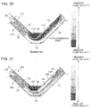
- FIG.19 is a top view of the conventional corrugated plate.
- the collecting plate 110 of the conventional corrugated plate 111 is fixed to the slope portion 72 at a base end thereof and a tip end thereof protrudes toward the upstream in the direction of the moist steam flow S1.
- the collecting plate 110 bends such that the tip end is closer to the body portion of the corrugated plate 111.
- a pocket section 112 is formed between the collecting plate 110 and the body portion of the corrugated plate 111.
- FIG.20 and FIG.21 are contour maps showing a part of flow velocity distribution between the corrugated plates in the conventional case and the example case.
- a flow separation area (the area surrounded by dotted lines in FIG.20 ) is generated in the flow passage.
- the flow separation area extends to a downstream area of the collecting plate 110.
- the moist steam S1 streams in the steam passage at approximately the same flow velocity as in the conventional case. It is confirmed that the drain duct part 108 is provided in the flow separation area described above, and that there is almost no loss of the flow caused by the flow velocity decline or the like due to the provision of the drain duct section 108.
- the drain plate 80 is downwardly-inclined toward a downstream side in the flow direction of the moist steam S1.
- the drain plate 80 may be arranged horizontally. In such a case, the moisture having reached the drain plate 80 is pushed by the moist steam S1 and can flow toward the downstream side.
- the chevron-vane type moisture separator 16 which is applied to the moisture separator/heater is explained.
- this is not limitative and the present invention is also applicable to another chevron-vane type moisture separator.
- FIG.22 shows a structure of a wet electrostatic precipitator to which the moisture separator of the present invention is applicable.
- This type of wet electrostatic precipitator is used, for instance, in a blast-furnace gas fired gas turbine combined-cycle system to remove dust from the moisture of fuel gas.
- fuel gas enters an inlet duct 91 in a direction of the arrow of FIG.22 and passes through perforated lattice windows 92 to a discharge electrode 93 and then a dust collecting electrode 94. In the process, the dust is removed from the fuel gas and then the fuel gas reaches an outlet duct 95.
- a moisture separator that is similar to the moisture separator 16 explained in reference to FIG.3 through FIG.18 and FIG.23 can be applied to the moisture separator 96 used in the wet electrostatic precipitator 90 described above.
- the present invention can be used as a chevron-vane type moisture separator that is capable of, even with an increased height of a corrugated plate, suppressing increase in thickness of the liquid film formed by the moisture collected by the corrugated plate and of suppressing decrease in performance of moisture separation caused by the re-entrainment of the moisture collected by the corrugated plate.
Landscapes
- Engineering & Computer Science (AREA)
- Physics & Mathematics (AREA)
- General Engineering & Computer Science (AREA)
- Thermal Sciences (AREA)
- Mechanical Engineering (AREA)
- Chemical & Material Sciences (AREA)
- High Energy & Nuclear Physics (AREA)
- Chemical Kinetics & Catalysis (AREA)
- Analytical Chemistry (AREA)
- General Chemical & Material Sciences (AREA)
- Oil, Petroleum & Natural Gas (AREA)
- Plasma & Fusion (AREA)
- Separating Particles In Gases By Inertia (AREA)
Description
- The present invention relates to a moisture separator which separates moisture from steam, and is applicable to, for example, a power generation plant such as a nuclear power plant and a blast-furnace gas (BFG) fired gas turbine combined-cycle (GTCC) system.
- A moisture separator is normally used in a power generation plant such as a nuclear power plant to eliminate moisture from steam generated in a steam generator or to eliminate moisture from moist steam discharged from a high pressure turbine so as to supply dry steam toward a low pressure turbine. This suppresses erosion of the turbine blades and also improves plant efficiency.
- A chevron-vane type moisture separator is known as one of such moisture separators. The chevron-vane type moisture separator is, for example, disclosed in
Patent Literature 1. -
FIG.23 is a perspective view of a conventional moisture separator of chevron-vane type. -
FIG.23 shows amoisture separator 60 where a plurality ofcorrugated plates 63 are mounted between anupper frame 61 and alower frame 62. Eachcorrugated plate 63 has a zigzag cross-sectional shape with projections and depressions that are arranged alternately. Each of flat parts has a pocket section. Moist steam S1 enters themoisture separator 60 in a direction of an arrow and moisture contained in the moist steam S1 adheres on a surface of thecorrugated plate 63. Then the moisture streaming in a flow direction of the moist steam S1 along the surface of thecorrugated plate 63 is captured at the pocket section and retained in the pocket section. - The retained moisture flows down along the surface of the
corrugated plate 63 and falls down into agroove 65 provided below. Moisture flying along the stream of the moist steam S1 collides against thecorrugated plate 63 and is captured by the pocket section in the same manner as above to be separated from the moist steam S1. - The moist steam S1, from which the moisture is removed by the
moisture separator 60, becomes dry steam S2 and is heated by a heating means (not shown) such as a group of heating tubes provided separately. - [PTL 1]
JP2002-311180A - Also, documents
JP S56 53716 A JP 2002 126429 A DE 195 13 201 C1 andUS 2004/069243 A1 disclose various examples of conventional moisture separators. - Recently, it is desired to increase a size of a nuclear power plant in which a moisture separator is used. With such increase in the size of the nuclear power plant in which the moisture separator is used, an amount of steam introduced to the moisture separator increases, the flow velocity of the steam streaming through the moisture separator becomes higher and thus, it becomes difficult to separate the moisture sufficiently by the moisture separator.
- Therefore, it is necessary, in response to the increasing size of the nuclear power plant, to make a larger moisture separator so as to avoid the gain in the flow velocity of the steam streaming through the moisture separator in comparison to the conventional case. Specifically, it is necessary to make the
corrugated plate 63 ofFIG.23 taller. - However, making the
corrugated plate 63 taller causes, in comparison to the conventional case, higher load of collecting the moisture per each corrugated plate, which leads to a thicker liquid film formed by the moisture flowing down along the pocket section and a higher likelihood of re-entrainment of the moisture. This results in decrease in performance of moisture separation. -
FIG.24 is a graph showing a relationship between a flow velocity of steam entering the moisture separator of the related art and wetness of the steam at an outlet of the moisture separator of the related art. In the graph ofFIG.24 , the horizontal axis represents the flow velocity of the steam entering the moisture separator and the vertical axis represents the wetness of the steam at the outlet of the moisture separator. InFIG.24 , a shorter vane shown by a solid line indicates a moisture separator with a height of the conventional corrugated plate used prior to upsizing of the moisture separator, whereas a longer vane shown by a broken line indicates a moisture separator with a height of the corrugated plate in the case of upsizing the moisture separator. - As shown in
FIG.24 , in both cases of the shorter vane and the longer vane, once the flow velocity of the steam introduced to the moisture separator exceeds certain limit values (s1 and s2 respectively), wetness of the steam at the outlet of the moisture separator rapidly increases, in other words, the performance of the moisture separation drops. The limit values (s1 and s2) indicate limit flow velocity for moisture separation capacity of the corrugated plate. - At a flow velocity lower than the limit values (s1, s2), there is a slow increase in the wetness of the steam at the outlet of the moisture separator. This indicates performance decline of the moisture separation due to the re-entrainment of the moisture having been collected in the pocket. This tendency is greater especially in the case of the longer vane.
- In view of the issues of the related art, an object of the present invention is to provide a moisture separator that is capable of, even with an increased height of the corrugated plate, suppressing the performance drop of the moisture separation by suppressing increase in thickness of the liquid film formed by the moisture collected by the corrugated plate and by suppressing the re-entrainment of the moisture collected by the corrugated plate.
- To solve the above issues, the present invention provides a moisture separator as defined in the appended claims.
- The projection which is covered by the collecting plate herein refers to a part which projects toward the steam passage. For instance, from a viewpoint of a first steam passage formed on one side of the corrugated plate, the projection is a part projecting toward the first steam passage. On the other hand, from a view point of a second steam passage formed on the other side of the same corrugated plate, the projection is a part projecting toward the second steam passage. In the specification, when simply expressed as a "projection" of the corrugated plate, the projection of the corrugated plate refers to the part projecting toward an intended steam passage.
- By this configuration, the moisture collected in the pocket section streams into the drain duct section by the steam flow and flows down inside the drain duct section. Thus, by reducing the amount of the moisture flowing down inside the pocket section and suppressing the thickness of the liquid film, it is possible to suppress the re-entrainment of the moisture collected in the pocket section. By providing the drain duct section on the downstream side of the pocket section in the direction of the steam flow, the moisture flowing down inside the drain duct is unlikely to flow back into the steam passage due to the steam flow entering the pocket section. Thus, it is possible to suppress the re-entrainment of the moisture from the drain duct section. As a result, even with an increased height of the corrugated plate, the decrease in performance of moisture separation caused by the re-entrainment of the moisture can be suppressed.
- The collecting plate may be fixed to the corrugated plate on the downstream side of the projection in the direction of the steam flow. Of the space formed between the collecting plate and the corrugated plate, an upstream portion and a downstream portion in the direction of the steam flow may function as the pocket section and the drain duct section, respectively.
- In this manner, by fixing the collecting plate to the corrugated plate on the downstream side of the projection in the direction of the steam flow, the drain duct section is formed between an end part of the collecting plate and the corrugated plate. The drain duct section is arranged behind the projection and thus, the moisture flowing down inside the drain duct section is unlikely to flow back to the steam passage. Therefore, it is possible to effectively suppress the re-entrainment of the moisture collected in the drain duct section.
- Further, the corrugated plate may be arranged to satisfy a relationship of 0≤D/L≤0.5, where D is a length from the projection to a position to which the collecting plate is fixed, and L is a length between the projection and the depression of the corrugated plate.
- When the length D from the projection to the position to which the colleting plate is fixed is long, a large amount of the steam streams into the drain duct section. This may causes the collecting plate to come off from the corrugated plate. However, in the present invention, the collecting plate is fixed to the corrugated plate to satisfy the relationship of 0≤D/L≤0.5, where D is the length from the projection to the position to which the collecting plate is fixed, and L is the length between the projection and the depression of the corrugated plate, so as to control the steam flow entering the drain duct section. By this, it is possible to prevent the collecting plate from coming off from the corrugated plate.
- The above moisture separator may further include a drain plate which is provided between the collecting plate and the corrugated plate to direct the moisture collected in the pocket section to the drain duct section. The drain plate may be arranged horizontally or downwardly-inclined toward the downstream side in the direction of the steam flow.
- By providing the drain plate in the pocket section, the moisture collected in the pocket section above the drain plate flows down inside the pocket section and moves over the drain plate in its entirety to enter the drain duct section. Therefore, the moisture collected in the pocket section does not flow down inside the pocket section below the drain plate and thus, it is possible to suppress thickness of the liquid film by reducing the amount of moisture flowing down inside the pocket section.
- By arranging the drain plate horizontally or inclining the drain plate downwardly toward the downstream side in the direction of the steam flow, it is possible to prevent the moisture over the drain plate from flowing back to the steam passage from the pocket section.
- Alternatively, a plurality of the drain plates may be provided in a height direction of the pocket section.
- By providing the plurality of the drain plates in the pocket section, even with an increased height of the corrugated plate, it is possible to suppress thickness of the liquid film formed in the pocket section, thereby preventing the re-entrainment of the moisture.
- The above moisture separator may further include a duct plate which is provided on an outer surface of the collecting plate and extends vertically. The pocket section may be a space formed between the collecting plate and the corrugated plate and the drain duct section may be a space formed between the duct plate and the collecting plate. The drain duct section may be in communication with the pocket section through a drain through-hole which passes through the collecting plate.
- By arranging the collecting plate with the drain through-hole between the pocket section and the drain duct section, the moisture collected in the pocket section above the drain plate flows down inside the pocket section and moves over the drain plate in its entirety into the drain duct section through the drain through-hole. The moisture collected in the pocket section does not flows down inside the pocket section below the drain plate and thus, it is possible to suppress thickness of the liquid film by reducing the amount of the moisture flowing down the pocket section.
- By providing the collecting plate, there is no re-entrainment of the moisture entering the drain duct section and thus, the performance of moisture separation can be improved.
- The above moisture separator may also include a drain plate which is provided between the collecting plate and the corrugated plate to direct the moisture collected in the pocket section to the drain duct section via the drain through-hole. The drain plate may be arranged horizontally or be downwardly-inclined toward the downstream side in the direction of the steam flow.
- By arranging the drain plate in the pocket section, the moisture collected in the pocket section above the drain plate flows down inside the pocket section and moves over the drain plate in its entirety into the drain duct section. The moisture collected in the pocket section does not flows down inside the pocket section below the drain plate and thus, it is possible to suppress thickness of the liquid film by reducing the amount of the moisture flowing down inside the pocket section.
- By arranging the drain plate horizontally or inclining the drain plate downwardly toward the downstream side in the direction of the steam flow, it is possible to prevent the moisture over the drain plate from flowing back to the steam passage from the pocket section.
- Alternatively, a plurality of the drain plates may be provided in a height direction of the pocket section, and a plurality of the drain through-holes may be respectively provided for drain plates so that a top surface of each of the drain plates is in communication with the drain duct section.
- By providing the plurality of the drain plates in the pocket section, even with an increased height of the corrugated plate, it is possible to suppress thickness of the liquid film formed in the pocket section, thereby preventing the re-entrainment of the moisture.
- The above drain plates may be arranged so as to equally divide the pocket section in the height direction.
- By providing the plurality of drain plates to equally divide the pocket section in the height direction, an amount of the moisture collected between each adjacent pair of the drain plates is almost the same and thus, it is possible to prevent uneven performance of moisture separation depending on a position in the height direction.
- The above moisture separator may also include a backflow preventing member which is provided in the pocket section and prevents the moisture from flowing back from the pocket section to the steam passage.
- By providing the backflow preventing member in the pocket section, it is possible to prevent the moisture collected in the pocket section and the drain duct section from flowing back to the steam passage.
- According to the present invention, it is possible to provide the moisture separator that is capable of, even with an increased height of a corrugated plate, suppressing the performance drop of the moisture separation by suppressing increase in thickness of the liquid film formed by the moisture collected by the corrugated plate and by suppressing the re-entrainment of the moisture collected by the corrugated plate.
-
- [
FIG.1] FIG.1 is a side view of an axial central portion of a moisture separator/heater in an example, which is partially shown in section. - [
FIG.2] FIG.2 is a cross-sectional view taken along a line A-A ofFIG.1 . - [
FIG.3] FIG.3 is a top view of a part of a corrugated plate in relation to a first preferred embodiment of the present invention. - [
FIG.4] FIG.4 is a side view of a part of the corrugated plate in relation to the first preferred embodiment of the present invention. - [
FIG.5] FIG.5 is a perspective view of a corrugated plate in relation to the preferred embodiment. - [
FIG.6] FIG.6 is another example of the corrugated plate in relation to the preferred embodiment. - [
FIG.7] FIG.7 is a perspective view of a corrugated plate in relation to a second preferred embodiment of the present invention. - [
FIG.8] FIG.8 is a top view of the corrugated plate in relation to the second preferred embodiment of the present invention. - [
FIG.9] FIG.9 is a cross-sectional view taken along a line B-B ofFIG.8 . - [
FIG.10] FIG.10 is a perspective view of a corrugated plate in relation to a third preferred embodiment of the present invention. - [
FIG.11] FIG.11 is a top view of the corrugated plate in relation to the third preferred embodiment of the present invention. - [
FIG.12] FIG.12 shows another example of a backflow preventing member in relation to the preferred embodiment. - [
FIG.13] FIG.13 shows another example of the backflow preventing member in relation to the preferred embodiment. - [
FIG.14] FIG. 14 is a perspective view of a corrugated plate in relation to a fourth preferred embodiment of the present invention. - [
FIG.15] FIG.15 is a top view of the corrugated plate in relation to the fourth preferred embodiment of the present invention. - [
FIG.16] FIG.16 is a cross-sectional view taken along a line C-C ofFIG.15 . - [
FIG.17] FIG.17 shows another example of a divider wall in relation to the preferred embodiment. - [
FIG.18] FIG.18 is a top view of a corrugated plate in relation to a fifth preferred embodiment of the present invention. - [
FIG.19] FIG.19 is a top view of a conventional corrugated plate. - [
FIG.20] FIG.20 is a contour map showing a flow velocity distribution between the conventional corrugated plates. - [
FIG.21] FIG.21 is a contour map showing a flow velocity distribution between the corrugated plates in an example. - [
FIG.22] FIG.22 shows a structure of a wet electrostatic precipitator to which the moisture separator of the present invention is applicable. - [
FIG.23] FIG.23 is a perspective view of a chevron-vane type moisture separator of related art. - [
FIG.24] FIG.24 is a graph showing a relationship between a flow velocity of steam entering the moisture separator of the related art and wetness of the steam at an outlet of the moisture separator of the related art. - Preferred embodiments of the present invention will now be described in detail with reference to the accompanying drawings. It is intended, however, that unless particularly specified, dimensions, materials, shape, relative positions and the like of components described in the embodiments shall be interpreted as illustrative only and not limitative of the scope of the present invention.
- A moisture separator/heater to which a moisture separator of each preferred embodiment is applied is explained in reference to
FIG.1 andFIG.2 .FIG.1 is a side view of an axial central portion of the moisture separator/heater of a preferred embodiment, which is partially shown in section.FIG.2 is a cross-sectional view taken along a line A-A ofFIG.1 . - As shown in
FIG.1 andFIG.2 , a moisture separator/heater 1 essentially consists ofend plates 2 and acylindrical shell plate 4 in a center. Between theshell plate 4 and theend plates 2, adivider wall 3 is provided. - As shown in
FIG.1 , in a central part of theshell plate 4 in the axial direction except for a top part, asteam receiving chamber 6 is formed with asteam inlet port 8. - As shown in
FIG.2 , amanifold chamber 10 in communication with thesteam receiving chamber 6 is formed within theshell plate 4 nearer to each end in the axial direction, on an outer side in the radial direction and on an upper side except for the top part. In the lower part of themanifold chamber 10, adistributor plate 12 is arranged. Below themanifold chamber 10, amoisture separation chamber 14 is formed. In themoisture separation chamber 14, a chevron-vanetype moisture separator 16 in relation to the present invention is provided. - As shown in
FIG.1 , aheating chamber 36 is formed nearer to each end in the axial direction and on an inner side in the radial direction of theshell plate 4 , i.e. in a region surrounded by themanifold chamber 10 and themoisture separation chamber 14. Theheating chamber 36 is in communication with themoisture separation chamber 14. On a lower side in theheating chamber 36, a first-stage tube bundle 18 is arranged such as to direct tube ends toward the ends of theshell plate 4 in the axial direction. Above the first-stage tube bundle 18 in theheating chamber 36, a second-stage tube bundle 20 is arranged such as to direct the tube ends toward the ends of theshell plate 4 in the axial direction. - On both ends of the
shell plate 4 in the axial direction and in a lower part of the inner side in the radial direction, a first-stageheater steam room 22 is provided. The first-stageheater steam room 22 is partitioned into a distributingpart 22a and arecovery part 22b inside. On both ends of theshell plate 4 in the axial direction and in an upper part of the inner side in the radial direction, a second-stageheater steam room 24 is provided. The second-stageheater steam room 24 is partitioned into a distributingpart 24a and arecovery part 24b inside. - The distributing
parts heater steam rooms steam 23, 35 for heating. To therecovery parts heater steam rooms steam - To the distributing
part 22a, tube ends of one side of the first-stage tube bundle 18 are connected. To therecovery part 22b, tube ends of the other side of the first-stage tube bundle 18 are connected. In the same manner, to the distributingpart 24a, tube ends of one side of the second-stage tube bundle 20 are connected. To therecovery part 24b, tube ends of the other side of the second-stage tube bundle 20 are connected. - As shown in
FIG.1 andFIG.2 , in the top part within theshell plate 4, arecovery manifold chamber 26 is formed in a continuous manner in the axial direction of theshell plate 4. Therecovery manifold chamber 26 is in communication with theheating chamber 36. In the top part of theshell plate 4, a plurality ofsteam delivery ports 28 are provided in communication with therecovery manifold chamber 26 to feed the steam out to a low-pressure steam turbine (not shown). - An operation of the moisture separator/
heater 1 according to the preferred embodiment is explained now. - The steam S exhausted from devices located upstream such as a high-pressure steam turbine is supplied into the
steam receiving chamber 6 within theshell plate 4 from thesteam inlet port 8. Then, the steam S enters themanifold chamber 10. - Next, the steam S entering the
manifold chamber 10 streams through themoisture separator 16 within themoisture separation chamber 14 via thedistributor plate 12, resulting in separation of the moisture from the steam. Then, the steam having the moisture removed streams into theheating chamber 36. - After entering the
heating chamber 36, the steam S comes in contact with the first-stage tube bundle 18 and is heated by theheating steam 23 streaming in the first-stage tube bundle 18. The steam S comes in contact with the second-stage tube bundle 20 and is heated by theheating steam 25 streaming in the second-stage tube bundle 20. Then, the steam S enters therecovery manifold chamber 26. - After entering the
recovery manifold chamber 26, the steam S streams in therecovery manifold chamber 26 and is delivered through thesteam delivery port 28 to be supplied to the devices located downstream such as the low-pressure steam turbine. - The chevron-vane
type moisture separator 16 according to the present invention used in the moisture separator/heater 1 having the structure and operating as described above is now explained. -
FIG.3 and FIG.4 respectively show a top view and a side view of a part of a corrugated plate in relation to a first preferred embodiment of the present invention.FIG.5 is a perspective view of the corrugated plate in relation to the preferred embodiment. - As shown in
FIG.3 through FIG.5 , thecorrugated plate 63 of the preferred embodiment is provided with: a body portion of thecorrugated plate 63 having a slope portion 72 (a portion between a projection which projects toward the steam passage and a depression which is depressed with respect to the steam passage) and aflat portion 74; and a protrudingmember 73 which is formed to cover theflat portion 74 and which has an opening that opens to a moist steam flow S1. - The protruding
member 73 includes a collectingplate 76 which extends toward an upstream side from theslope portion 72 disposed on a downstream side of theflat portion 74 such as to cover the flat portion (projection) 74. The collectingplate 76 is fixed to theslope portion 72 at a base end thereof by welding or the like. The collectingplate 76 curves from the base end toward a tip end thereof. Between the collectingplate 76 and theflat portion 74, apocket section 77 is formed by the collectingplate 76. Thepocket section 77 is formed such that a depth and a width thereof are greater than a width of the inlet opening of the collectingplate 76 opening to the moist steam flow. The moist steam S1 streams along the surface of thecorrugated plate 63 and enters thepocket section 77. - The protruding
member 73 is arranged in contact with an outer surface of the collectingplate 76 at the downstream part thereof in the flow direction of the moist steam S1. The protrudingmember 73 includes aduct plate 78 extending in a height direction. Theduct plate 78 has an arc-shaped cross-section with each end fixed to the collectingplate 76. Adrain duct section 81 is formed between the collectingplate 76 and theduct plate 78 by theduct plate 78. Herein, thedrain duct section 81 and thepocket section 77 are partitioned by the collectingplate 76. - In the
pocket section 77 of the protrudingmember 73,drain plates 80 are provided to partition thepocket section 77 in the height direction. Thedrain plates 80 are downwardly-inclined toward the downstream side in the flow direction of the moist steam S1. - In the collecting
plate 76, a drain through-hole 82 is formed above thedrain plate 80 near a connection point of a plane passing through thedrain plate 80 with the collectingplate 76 such that a top surface of thedrain plates 80 are in communication with thedrain duct section 81. That is, the drain through-hole 82 communicates between the top surface of a lowest part of inclination of thedrain plate 80 and the inside of thedrain duct section 81. - In the
corrugated plate 63 configured as described above, in the case where the moist steam flow S1 streams through the steam passage between thecorrugated plates 63 in the direction of the arrow a as shown inFIG.3 through FIG.5 , the moisture contained in the moist steam S1 hits a surface of theslope portion 72 of thecorrugated plate 63 and turns into droplets on the surface of theslope portion 72 to adhere thereto. The droplets are pushed by the flow of the moist steam flow S1 along the surface of theslope portion 72 in the direction of the arrow a and reach theflat portion 74. At theflat portion 74, the droplets are pushed by the moist steam flow S1 and enter thepocket section 77 from the inlet opening of the collectingplate 76, forming a liquid film. Meanwhile, the moist steam flow S1 flows outside the collectingplate 76 toward the downstream side. Thus, it is possible to collect only the moisture in the collectingplate 76 smoothly. - The moisture collected in the
pocket section 77 as the liquid film, flows down inside thepocket section 77 by gravity. The moisture collected below thedrain plate 80 in thepocket section 77 flows down to a bottom inside thepocket section 77 and then falls down to a groove 65 (seeFIG.23 ) arranged below to be collected. - The moisture collected above the
drain plate 80 in thepocket section 77 flows down inside thepocket section 77 and reaches the top surface of thedrain plate 80. Then, the moisture is changed its direction by thedrain plate 80, and due to a tilt of thedrain plate 80 and by being pushed by the moist steam S1, flows downward on thedrain plate 80 in the direction of the tilt. Once the moisture reaches the drain through-hole 82, the moisture enters thedrain duct section 81 inside theduct plate 78 via the drain through-hole 82 and flows down inside thedrain duct section 81 to the bottom and then falls down to thegroove 65 to be collected. - As described above, according to the first preferred embodiment, the moisture collected in the
pocket section 77 above thedrain plate 80 moves over thedrain plate 80 and enters thedrain duct section 81. Then, the moisture flows down inside thedrain duct section 81 and thus, such moisture does not flows down inside thepocket section 77 below thedrain plate 80. This suppresses an amount of the moisture flowing down a lower part inside thepocket section 77, thereby reducing a thickness of the liquid film. As a result, it is possible to prevent re-entrainment of the moisture collected by thecorrugated plate 63. Thepocket section 77 and thedrain duct section 81 are partitioned by the collectingplate 76 so as to prevent re-entrainment of the moisture having entered thedrain duct section 81. Therefore, even with an increased height of thecorrugated plate 63, it is possible to suppress a decrease in performance of moisture separation caused by the re-entrainment of the moisture. - In the preferred embodiment, one set of the
drain plate 80 and the drain through-hole 82 is provided in onepocket section 77. However, this is not limitative and a plurality of thedrain plates 80 may be provided in the height direction depending on the height of theduct plate 78 as shown inFIG.6 . By this, even with an increased height of thecorrugated plate 63, it is possible to suppress the liquid film thickness in thepocket section 77. In such a case, the same number ofdrain plates 80 and the drain through-holes 82 need to be provided so that the top surface of each of thedrain plates 80 is in communication with thedrain duct section 81. - A second preferred embodiment of the present invention is now explained. Hereinafter, the same reference numerals are given without adding explanations for those configurations that are the same as the prior embodiment and mainly differences are addressed.
-
FIG.7 andFIG.8 respectively show a perspective view and a top view of a corrugated plate in relation to a second preferred embodiment of the present invention.FIG.9 is a cross-sectional view taken along a line B-B ofFIG.8 . - As shown in
FIG.7 through FIG.9 , acorrugated plate 43 of the second preferred embodiment is provided with a collectingplate 49 which is formed to cover an upstream end of theslope portion 72 disposed on the downstream side of the flat portion 74 (projection which projects toward the steam passage) and also to cover theflat portion 74. The collectingplate 49 has an opening that opens to the moist steam flow S1. The collectingplate 49 is fixed to theslope portion 72 at the base end thereof. The collectingplate 49 includes a plurality of bends between the base end and a tip end such that an overall shape of the collectingplate 49 is formed along the shape of the body portion of thecorrugated plate 43. Specifically, at a first bend, the collectingplate 49 bends outward from the base end toward the tip end in a direction away from the body portion of thecorrugated plate 43. At a second bend, with a certain distance away from the body portion of thecorrugated plate 43, the collectingplate 49 bends to be shaped along theslope portion 72. At a third bend on the upstream side of the second bend, the collectingplate 49 bends to be shaped along the flat portion (projection) 74. At a fourth bend on the upstream side of the third bend, the collectingplate 49 bends to be shaped along theslope portion 72. - The
pocket section 47 which the moist steam S1 flowing along the surface of thecorrugated plate 43 enters, and thedrain duct portion 48 which is adjacent to thepocket section 47 on the downstream side of the moist steam flow and extends approximately to a middle of theslope portion 72 are formed by the collectingplate 49. Herein, a relationship between a length D from aboundary position 75 between the flat portion (projection) 74 and theslope portion 72 on the downstream side of theflat portion 74 to adownstream end 48a of thedrain duct section 48 in the direction of the moist steam flow (a position to which the collectingplate 49 is fixed), and a length L of the slope portion 72 (a portion between the projection projecting toward the steam passage and the depression depressed from the steam passage) is represented by Formula (1) below.
- In the preferred embodiment, the length D from the
boundary position 75 to thedownstream end 48a of thedrain duct section 48 in the direction of the moist steam flow is set to just half of the length L of theslope portion 72. However, this is not limitative and it is only necessary that thedrain duct section 48 is formed so as to satisfy a relationship of 0≤D/L≤0.5 wherein D is a length from theboundary position 75 to thedownstream end 48a of thedrain duct section 48 in the direction of the moist steam flow and L is a length of theslope portion 72. - In the
pocket section 47 of the collectingplate 49, a plurality ofdrain plates 80 are provided such as to partition thepocket section 47 at equal intervals in the height direction. Each of thedrain plates 80 is downwardly-inclined toward the downstream side in the flow direction of the moist steam S1. In the preferred embodiment, thedrain plates 80 are provided such as to partition thepocket section 47 at equal intervals in the height direction. However, this is not limitative. - In the
corrugated plate 43 with the above structure, in the case where the moist steam flow S1 streams between thecorrugated plates 43 in the direction of the arrow a as shown inFIG.7 andFIG.8 , in a manner similar to the first preferred embodiment, the moisture contained in the moist steam S1 turns into droplets and enters thepocket section 47 from the inlet opening of the collectingplate 49, forming a liquid film therein. - A part of the moisture in the
pocket section 47 is pushed by the moist steam S1 streaming into thepocket section 47 to enter thedrain duct section 48 and forms a liquid film therein. Meanwhile, a large part of the moist steam flow S1 passing through the flow passage flows outside the collectingplate 49 toward the downstream side. - The moisture collected in the
drain duct section 48 and thepocket section 47 as the liquid film flows down inside thedrain duct section 48 and thepocket section 47 respectively by gravity. The moisture in thedrain duct section 48 is pushed by the moist steam flow S1 and flows down while moving deeper to the downstream side. Then, the moisture falls down to thegroove 65 arranged below to be collected. - The moisture flowing down inside the
pocket section 47 reaches the top surface of each of thedrain plates 80 and flows downward over thedrain plate 80 in the direction of the tilt. Then, the moisture enters thedrain duct section 48, flows down inside thedrain duct section 48 to the bottom and falls down to thegroove 65 to be collected. - As described above, according to the second preferred embodiment, the moisture collected in the
pocket section 47 above each of thedrain plates 80 moves over eachdrain plate 80 into thedrain duct section 48 and flows down inside thedrain duct section 48. This suppresses an amount of the moisture flowing down inside thepocket section 47, thereby reducing thickness of the liquid film. As a result, it is possible to prevent re-entrainment of the moisture collected by thecorrugated plate 43. Further, as the moisture flowing down inside thedrain duct section 48 flows down deep inside the drain duct section, it is possible to suppress re-entrainment of the moisture. Therefore, even with an increased height of thecorrugated plate 43, it is possible to suppress a decrease in performance of moisture separation caused by the re-entrainment of the moisture. - Further, the collecting
plate 49 is constituted of asingle collecting plate 49 and thus, is inexpensive to make and easy to mount to the body portion of thecorrugated plate 43. - In the second preferred embodiment, a plurality of the
drain plates 80 are provided in eachpocket section 47. However, this is not limitative and only onedrain plate 80 may be provided in eachpocket section 47. In such a case, thedrain plate 80 is preferably provided at a height that is approximately half of the height of thecorrugated plate 43. - A third preferred embodiment of the present invention is explained now.
-
FIG.10 andFIG.11 respectively show a perspective view and a top view of a corrugated plate in relation to the third preferred embodiment of the present invention. - As shown in
FIG.10 andFIG.11 , thecorrugated plate 54 of the third preferred embodiment is provided with the collectingplate 49 in a manner similar to the second preferred embodiment. Between the collectingplate 49 and the body portion of thecorrugated plate 54, thepocket section 47 and thedrain duct section 48 are formed. Further, a plurality of thedrain plates 80 are provided in thepocket section 47. - On the
flat portion 74 in thepocket section 47 of the third preferred embodiment, a plurality ofbackflow preventing members 52 are provided in the height direction. Thebackflow preventing member 52 has a cross section that is substantially U-shape. Thebackflow preventing member 52 is fixed to theflat portion 74 such that an opening of the U-shaped cross section faces toward thedrain duct section 48. Thebackflow preventing member 52 is provided over a highest one of thedrain plates 80, between each pair ofadjacent drain plates 80 and under a lowest one of thedrain plates 80. - In the
corrugated plate 54 having the above structure, when the moisture in thedrain duct section 48 of the moisture collected in thepocket section 47 and thedrain duct section 48 flows back toward thepocket section 47, while flowing down by gravity, due to the moist steam S1 streaming between the collectingplate 49 and the body portion of thecorrugated plate 54, such backflow is prevented by thebackflow preventing member 52 provided in thepocket section 47, and the refluent moisture (the part of the moisture flowing back toward the pocket section) enters aconcave portion 52a of thebackflow preventing member 52. The refluent moisture captured in theconcave portion 52a flows down inside theconcave portion 52a by gravity and reaches the top surface of each of thedrain plates 80. Then, the refluent moisture flows downward over thedrain plate 80 in the direction of the tilt. The moisture enters thedrain duct section 48 and flows down inside thedrain duct section 48 to the bottom and then falls down to thegroove 65 to be collected. - According to the third preferred embodiment as described above, in addition to the effects of the second preferred embodiment, it is now possible to prevent the moisture flowing down inside the
drain duct section 48 from flowing back into the steam passage, thereby suppressing the re-entrainment of the moisture having been collected by thecorrugated plate 54. - In the third preferred embodiment, the
backflow preventing member 52 has the substantially U-shaped cross section. However, this is not limitative. For instance, a backflow preventing member having a substantially L-shaped cross section as shown inFIG. 12 , or a backflow preventing member having a substantially V-shaped cross section as shown inFIG.13 may be used. Thebackflow preventing member 52 may have any shape as long as it is capable of preventing the moisture flowing down inside thedrain duct section 48 from flowing out of the collectingplate 49. - A fourth preferred embodiment of the present invention is explained now.
-
FIG.14 andFIG.15 respectively show a perspective view and a top view of a corrugated plate in relation to the fourth preferred embodiment of the present invention.FIG.16 is a cross-sectional view taken along a line C-C ofFIG.15 . - As shown in
FIG.14 through FIG.16 , acorrugated plate 53 of the fourth preferred embodiment is provided with the collectingplate 49 in the same manner as the second and third preferred embodiments, and thepocket section 47 and thedrain duct section 48 are formed between the collectingplate 49 and the body portion of thecorrugated plate 53. In thepocket section 47, a plurality of thedrain plates 80 are provided. - A
divider wall 59 is provided between the collectingplate 49 and the body portion of thecorrugated plate 53 to divide a space formed therebetween into thepocket section 47 and thedrain duct section 48. Thedivider wall 59 has the same height as thecorrugated plate 53 and is arranged along the height direction of thecorrugated plate 53. - To a side surface of the
divider wall 59, an end of thedrain plate 80 is connected. Thedivider wall 59 has drain through-holes 82 formed above thedrain plates 80 so that the top surfaces of thedrain plates 80 are in communication with thedrain duct section 48. - In the
corrugated plate 53 having the above structure, the moisture collected in thepocket section 47 flows down inside thepocket section 47 by gravity. The moisture collected in thepocket section 47 below the lowest one of thedrain plates 80 flows down to the bottom and then falls down to thegroove 65 provided below to be collected. - In contrast, the moisture collected in the
pocket section 47 above each of thedrain plates 80 flows down inside thepocket section 47 and once reaching each of thedrain plates 80, in the same manner as the first preferred embodiment, the moisture flows downward over each of thedrain plates 80 in the direction of the tilt of thedrain plate 80 and enters thedrain duct section 48 through the drain through-hole 82. Then, the moisture flows down inside thedrain duct section 48 to the bottom and then falls down to thegroove 65 provided below and is collected. - According to the fourth preferred embodiment described above, the moisture collected in the
pocket section 47 above eachdrain plate 80 moves over thedrain plate 80, enters thedrain duct section 48 and flows down inside thedrain duct section 48. Thus, the moisture does not flow down inside thepocket section 47 below thedrain plate 80. This suppresses an amount of the moisture flowing down a lower part of thepocket section 47, thereby reducing a thickness of the liquid film. As a result, it is possible to prevent re-entrainment of the moisture collected by thecorrugated plate 53. - The
pocket section 47 and thedrain duct section 48 are partitioned by thedivider wall 59 so as to prevent the moisture having entered thedrain duct section 48 from flowing back into the steam passage via thepocket section 47, thereby suppressing the re-entrainment of the moisture. Therefore, even with an increased height of thecorrugated plate 53, it is possible to suppress a decrease in performance of moisture separation caused by the re-entrainment of the moisture. - In the fourth preferred embodiment, the
divider wall 59 has the same height as thecorrugated plate 53. However, this is not limitative, and thedivider wall 59 may be shorter than thecorrugated plate 53 as shown inFIG. 17 . In such a case, the number and positions of thedrain plates 80 are adjusted depending on the height of thedivider wall 59. - A fifth preferred embodiment of the present invention is explained now.
-
FIG.18 is a top view of a corrugated plate in relation to the fifth preferred embodiment of the present invention. - As shown in
FIG.18 , acorrugated plate 103 of the fifth preferred embodiment is provided with a collectingplate 109, aduct plate 101 and thedrain plate 80. The collectingplate 109 is formed to cover the flat portion 74 (the projection projecting toward the steam passage) and has an opening that opens to the moist steam flow S1. Theduct plate 101 is arranged in contact with an outer surface of the collectingplate 109. - The collecting
pate 109 extends toward the upstream side in the direction of the steam flow from theslope portion 72 disposed on a downstream side of theflat portion 74 such as to cover theflat portion 74. The collectingplate 109 is fixed to theslope portion 72 at a base end thereof. The collectingplate 109 bends, from the base end toward a tip end thereof, at a first bend to be shaped along theflat portion 74, and at a second bend upstream of the first bend, the collectingplate 109 bends to be shaped along aslope portion 72 disposed on the upstream side of theflat portion 74. Apocket section 107 which the moist steam S1 streaming along the surface of thecorrugated plate 103 enters is formed by the collectingplate 109. - The
duct plate 101 is arranged in contact with an outer surface of the collectingplate 109 at the downstream side in the flow direction of the moist steam S1 and extends vertically. Theduct plate 101 is fixed to the downstream part of the collectingplate 109 at a base end thereof. Theduct plate 101 bends, from the base end toward the tip end thereof, at a first bend outward away from thecorrugated plate 103. At a second bend on an upstream side of the first bend, theduct plate 101 bends to be shaped along theslope portion 72. At a third bend on the upstream side of the second bend, theduct plate 101 bends to be shaped along theflat portion 74. Theduct plate 101 is fixed to the collectingplate 109 at the tip end thereof. Theduct plate 101 is half the height of thecorrugated plate 103. - By the
duct plate 101, adrain duct section 108 is formed between theduct plate 101 and the collectingplate 109. In a manner similar to the second preferred embodiment, thedrain duct section 108 satisfies the relationship defined by the formula (1) wherein D is a length from theboundary position 75 between theflat portion 74 and theslope portion 72 to adownstream end 108a of thedrain duct section 108 in the direction of the moist steam flow and L is a length of theslope portion 72. - The
pocket section 107 and thedrain duct section 108 are partitioned by the collectingplate 109. The collectingplate 109 has the through-hole 82 formed therein. A top surface of a lowest part of inclination of thedrain plate 80 provided in thepocket section 107 is in communication with thedrain duct section 108 via the drain through-hole 82. - According to the fifth preferred embodiment, in a manner similar to each of the above preferred embodiments, the moisture collected in the
pocket section 107 above thedrain plate 80 moves over thedrain plate 80 and enters thedrain duct section 108. Thus, such moisture does not flow down inside thepocket section 107 below thedrain plate 80. This suppresses an amount of the moisture flowing down at a lower part inside thepocket section 107, thereby reducing a thickness of the liquid film. As a result, it is possible to prevent re-entrainment of the moisture collected by thecorrugated plate 103. Thepocket section 107 and thedrain duct section 108 are partitioned by the collectingplate 109 so as to prevent re-entrainment of the moisture having entered thedrain duct section 108. Therefore, even with an increased height of thecorrugated plate 103, it is possible to suppress a decrease in performance of moisture separation caused by the re-entrainment of the moisture. - In the fifth embodiment, the flow velocity of the moist steam S1 streaming in the steam passage was analyzed by a Computational Fluid Dynamics (CFD) analysis, for an example case where the
corrugated plate 103 including the collectingplate 109 and theduct plate 101 is used and a conventional case where a corrugated plate including a conventional protruding member is used. - The conventional corrugated plate is explained now.
FIG.19 is a top view of the conventional corrugated plate. As shown inFIG.19 , the collectingplate 110 of the conventionalcorrugated plate 111 is fixed to theslope portion 72 at a base end thereof and a tip end thereof protrudes toward the upstream in the direction of the moist steam flow S1. The collectingplate 110 bends such that the tip end is closer to the body portion of thecorrugated plate 111. By the collectingplate 110, apocket section 112 is formed between the collectingplate 110 and the body portion of thecorrugated plate 111. - When the moist steam S1 streams along the
corrugated plate 111 having the above structure, the moisture is collected in thepocket section 112 and then flows down inside thepocket section 112. - As described above, the CFD analysis of the flow velocity of the moist steam S1 in the example case using the
corrugated plate 103 and the conventional case using thecorrugated plate 111 was performed. -
FIG.20 and FIG.21 are contour maps showing a part of flow velocity distribution between the corrugated plates in the conventional case and the example case. - In the conventional case shown in
FIG.20 , an area where the flow velocity is small, i.e. a flow separation area (the area surrounded by dotted lines inFIG.20 ) is generated in the flow passage. The flow separation area extends to a downstream area of the collectingplate 110. - In contrast, in the example case shown in
FIG.21 , the moist steam S1 streams in the steam passage at approximately the same flow velocity as in the conventional case. It is confirmed that thedrain duct part 108 is provided in the flow separation area described above, and that there is almost no loss of the flow caused by the flow velocity decline or the like due to the provision of thedrain duct section 108. - Therefore, also in the first through fourth preferred embodiments, there is almost no loss in the flow due to provision of the
drain duct sections - In each of the above preferred embodiments, the
drain plate 80 is downwardly-inclined toward a downstream side in the flow direction of the moist steam S1. However, this is not limitative and thedrain plate 80 may be arranged horizontally. In such a case, the moisture having reached thedrain plate 80 is pushed by the moist steam S1 and can flow toward the downstream side. - In each of the above preferred embodiments, the chevron-vane
type moisture separator 16 which is applied to the moisture separator/heater is explained. However, this is not limitative and the present invention is also applicable to another chevron-vane type moisture separator. - Another example of applying the present invention is explained.
-
FIG.22 shows a structure of a wet electrostatic precipitator to which the moisture separator of the present invention is applicable. This type of wet electrostatic precipitator is used, for instance, in a blast-furnace gas fired gas turbine combined-cycle system to remove dust from the moisture of fuel gas. - In a wet
electrostatic precipitator 90 shown inFIG.22 , fuel gas enters aninlet duct 91 in a direction of the arrow ofFIG.22 and passes throughperforated lattice windows 92 to adischarge electrode 93 and then adust collecting electrode 94. In the process, the dust is removed from the fuel gas and then the fuel gas reaches anoutlet duct 95. - By the
moisture separator 96 of chevron type installed to theoutlet duct 95, the mist is removed from the fuel gas. - A moisture separator that is similar to the
moisture separator 16 explained in reference toFIG.3 through FIG.18 andFIG.23 can be applied to themoisture separator 96 used in the wetelectrostatic precipitator 90 described above. - The present invention can be used as a chevron-vane type moisture separator that is capable of, even with an increased height of a corrugated plate, suppressing increase in thickness of the liquid film formed by the moisture collected by the corrugated plate and of suppressing decrease in performance of moisture separation caused by the re-entrainment of the moisture collected by the corrugated plate.
-
- 1
- Moisture separator/heater
- 16
- Moisture separator
- 36
- Heating chamber
- 43
- Corrugated plate
- 47
- Pocket section
- 48
- Drain duct section
- 48a
- Downstream end in the direction of the moist steam flow
- 49
- Collecting plate
- 52
- Backflow preventing member
- 52a
- Concave portion
- 53
- Corrugated plate
- 54
- Corrugated plate
- 59
- Divider wall
- 60
- Moisture separator
- 61
- Upper frame
- 62
- Lower frame
- 63
- Corrugated plate
- 65
- Groove
- 72
- Slope portion
- 73
- Protruding member
- 74
- Flat portion
- 75
- Boundary position
- 76
- Collecting plate
- 77
- Pocket section
- 78
- Duct plate
- 80
- Drain plate
- 81
- Drain duct section
- 82
- Drain through-hole
- 90
- Wet electrostatic precipitator
- 96
- Moisture separator
- 101
- Duct plate
- 103
- Corrugated plate
- 107
- Pocket section
- 108
- Drain duct section
- 108a
- Downstream end in the direction of the moist steam flow
- 109
- Collecting plate
- 110
- Conventional collecting plate
- 111
- Conventional corrugated plate
- 112
- Conventional pocket section
Claims (7)
- A moisture separator which separates moisture from moist steam, comprising:a plurality of corrugated plates (43, 53, 54) each having a zigzag cross-sectional shape with projections and depressions that are arranged alternately, said plurality of corrugated plates (43, 53, 54) being arranged at predetermined intervals to form a steam passage for the moist steam; anda plurality of collecting plates (49) which are fixed to the corrugated plates (43, 53, 54), each of said collecting plates (49) extending toward an upstream side in a direction of a steam flow within the steam passage so as to cover each of the projections of the corrugated plate (43, 53, 54),wherein between the collecting plate (49) and each of the corrugated plates (43, 53, 54), a pocket section (47) is formed with an opening which opens to the upstream side in the direction of the steam flow,wherein a drain duct section (48) is provided on a downstream side of the pocket section (47) in the direction of the steam flow and is in communication with the pocket section (47), said drain duct extending vertically,wherein the collecting plate (49) is fixed to the corrugated plate (43, 53, 54) on a downstream side of the projection in the direction of the steam flow, andwherein, of a space formed between the collecting plate (49) and the corrugated plate (43, 53, 54), an upstream portion and a downstream portion in the direction of the steam flow function as the pocket section (47) and the drain duct section (48), respectively,characterized in that the moisture separator further comprises a drain plate (80) which is provided between the collecting plate (49) and the corrugated plate (43, 53, 54) to direct the moisture collected in the pocket section (47) to the drain duct section (48),and in that the drain plate (80) is arranged horizontally or is downwardly-inclined toward a downstream side in the direction of the steam flow.
- The moisture separator according to claim 1,
wherein a relationship of 0≤D/L≤0.5 is satisfied, where D is a length from the projection to a position to which the collecting plate (49) is fixed, and L is a length between the projection and the depression of the corrugated plate (43, 53, 54). - The moisture separator according to claim 1 or 2,
wherein a plurality of said drain plates (80) are provided in a height direction of the pocket section (47). - A moisture separator which separates moisture from moist steam, comprising:a plurality of corrugated plates (63, 103) each having a zigzag cross-sectional shape with projections and depressions that are arranged alternately, said plurality of corrugated plates (63, 103) being arranged at predetermined intervals to form a steam passage for the moist steam; anda plurality of collecting plates (76, 109) which are fixed to the corrugated plates (63, 103), each of said collecting plates (76, 109) extending toward an upstream side in a direction of a steam flow within the steam passage so as to cover each of the projections of the corrugated plate (63, 103),wherein between the collecting plate (76, 109) and each of the corrugated plates (63, 103), a pocket section (77, 107) is formed with an opening which opens to the upstream side in the direction of the steam flow,wherein a drain duct section (81, 108) is provided on a downstream side of the pocket section (77, 107) in the direction of the steam flow and is in communication with the pocket section (77, 108), said drain duct extending vertically,characterized in that the moisture separator further comprises a duct plate (78, 101) which is provided on an outer surface of the collecting plate (76, 109) and extends vertically,in that the pocket section (77, 107) is formed between the collecting plate (76, 109) and the corrugated plate (63, 103) and the drain duct section (81, 108) is formed between the duct plate (78, 101) and the collecting plate (76, 109),in that the drain duct section (81, 108) is in communication with the pocket section (77, 107) through a drain through-hole (82) which passes through the collecting plate (76, 109),in that the moisture separator further comprises a drain plate (80) which is provided between the collecting plate (76, 109) and the corrugated plate (63, 103) to direct the moisture collected in the pocket section (77, 107) to the drain duct section (81, 108) via the drain through-hole (82),and in that the drain plate (80) is arranged horizontally or is downwardly-inclined toward a downstream side in the direction of the steam flow.
- The moisture separator according to claim 4,
wherein a plurality of said drain plates (80) are provided in a height direction of the pocket section (77, 107), and
wherein a plurality of the drain through-holes (82) are respectively provided so that a top surface of each of the drain plates (80) is in communication with the drain duct section (81, 108). - The moisture separator according to claim 3 or 5,
wherein the plurality of drain plates (80) are arranged so as to equally divide the pocket section (47, 77, 107) in the height direction. - The moisture separator according to any one of claims 1 to 6, further comprising:a backflow preventing member (52) which is provided in the pocket section (47) and prevents the moisture collected in the pocket section (47) from flowing back to the steam passage.
Applications Claiming Priority (3)
| Application Number | Priority Date | Filing Date | Title |
|---|---|---|---|
| JP2010263689 | 2010-11-26 | ||
| JP2011164557A JP5721579B2 (en) | 2010-11-26 | 2011-07-27 | Moisture separator |
| PCT/JP2011/076069 WO2012070411A1 (en) | 2010-11-26 | 2011-11-11 | Moisture separation device |
Publications (3)
| Publication Number | Publication Date |
|---|---|
| EP2623177A1 EP2623177A1 (en) | 2013-08-07 |
| EP2623177A4 EP2623177A4 (en) | 2014-07-02 |
| EP2623177B1 true EP2623177B1 (en) | 2016-04-20 |
Family
ID=46125710
Family Applications (1)
| Application Number | Title | Priority Date | Filing Date |
|---|---|---|---|
| EP11842598.2A Not-in-force EP2623177B1 (en) | 2010-11-26 | 2011-11-11 | Moisture separation device |
Country Status (6)
| Country | Link |
|---|---|
| US (1) | US8790433B2 (en) |
| EP (1) | EP2623177B1 (en) |
| JP (1) | JP5721579B2 (en) |
| KR (1) | KR101596106B1 (en) |
| CN (1) | CN103180024B (en) |
| WO (1) | WO2012070411A1 (en) |
Families Citing this family (21)
| Publication number | Priority date | Publication date | Assignee | Title |
|---|---|---|---|---|
| JP4848333B2 (en) * | 2007-09-07 | 2011-12-28 | 三菱重工業株式会社 | Moisture separator heater |
| DE102012014309B4 (en) * | 2012-07-19 | 2022-06-30 | Airbus Operations Gmbh | Particle separator for an air duct, air distribution system and use of a particle separator |
| CN103861389A (en) * | 2012-12-14 | 2014-06-18 | 中国核动力研究设计院 | Steam-water separator splitter applied in nuclear power plant steam generator |
| CN103372349B (en) * | 2013-05-30 | 2015-07-15 | 浙江天地环保工程有限公司 | Demisting device for outlet flue of desulfurization tower |
| EP2811227B1 (en) | 2013-06-06 | 2018-03-28 | General Electric Technology GmbH | Moisture separator configuration |
| CN105327552B (en) * | 2014-06-25 | 2017-09-19 | 普尔利斯(中国)环保分离设备制造有限公司 | Double pouch-type blade-type separators for separating liquid from gas |
| KR101945410B1 (en) * | 2014-07-25 | 2019-02-07 | 한화파워시스템 주식회사 | Separator |
| US10553322B2 (en) * | 2015-09-28 | 2020-02-04 | Ge-Hitachi Nuclear Energy Americas Llc | Modular fluid flow distribution system in which differently shaped plates can be rearranged to different positions |
| CN105423272B (en) * | 2015-12-24 | 2018-02-13 | 哈尔滨锅炉厂有限责任公司 | High-efficiency steam-water separator and separation method |
| CN105537873B (en) * | 2016-01-06 | 2019-01-11 | 上海发电设备成套设计研究院 | A kind of hydrophobic hook corrugated plating forming manufacturing method |
| CN105749628B (en) * | 2016-04-13 | 2018-01-19 | 上海发电设备成套设计研究院 | A kind of steam-water separation corrugated plating and separator |
| CN105749627A (en) * | 2016-04-13 | 2016-07-13 | 上海发电设备成套设计研究院 | Steam-water separator formed by corrugated plates with unequal distances |
| CN106178747B (en) * | 2016-08-20 | 2018-11-06 | 浙江众立机械制造有限公司 | Cleaner |
| JP7144265B2 (en) * | 2018-10-02 | 2022-09-29 | 三菱重工業株式会社 | moisture separators and steam turbine plants |
| JP7300639B2 (en) * | 2019-03-25 | 2023-06-30 | パナソニックIpマネジメント株式会社 | Heat exchange unit and absorption chiller |
| KR102103835B1 (en) * | 2019-10-16 | 2020-04-23 | 주식회사 에코이엔지 | Apparatus for capture dust |
| KR102340656B1 (en) * | 2019-12-10 | 2021-12-17 | 두산중공업 주식회사 | Chevron vane and moisture separator comprising the same |
| WO2021207949A1 (en) * | 2020-04-14 | 2021-10-21 | 深圳市迪尔安科技有限公司 | Oil fume separator for kitchen range hood |
| US11828230B2 (en) * | 2021-10-04 | 2023-11-28 | General Electric Company | System and method for mitigating particulate intrusion to an air intake system of a gas turbine system with intrusion protective coatings tailored to locale of operation |
| CN114100254A (en) * | 2021-11-26 | 2022-03-01 | 中国核动力研究设计院 | Integrated corrugated plate and dryer |
| CN114704339B (en) * | 2022-03-09 | 2023-09-08 | 中国船舶重工集团公司第七0三研究所 | Beryllium tip type dehumidifying device |
Family Cites Families (21)
| Publication number | Priority date | Publication date | Assignee | Title |
|---|---|---|---|---|
| DE2251173C2 (en) * | 1972-10-19 | 1979-08-30 | L. & C. Steinmueller Gmbh, 5270 Gummersbach | Separation device |
| JPS50128873A (en) * | 1974-03-29 | 1975-10-11 | ||
| JPS5145376A (en) * | 1974-10-16 | 1976-04-17 | Hitachi Ltd | SHITSUBUN BUNRISOCHI |
| JPS52130072A (en) * | 1976-04-23 | 1977-11-01 | Hitachi Ltd | Separator element of corrugated-plant type separator |
| DE2726524C2 (en) * | 1977-06-11 | 1984-04-12 | Ulrich Dr.-Ing. 5100 Aachen Regehr | Device for separating liquid droplets |
| JPS5838205B2 (en) * | 1979-10-11 | 1983-08-22 | 株式会社日立製作所 | Corrugated plate support device for steam/water separation equipment |
| SE461318B (en) | 1982-10-12 | 1990-02-05 | Munters Ab Carl | DEVICE TO Separate water droplets or fine-grained solid matter from a gas stream |
| JPS59130514A (en) * | 1982-10-12 | 1984-07-27 | ウルリツヒ,レゲ−ル | Apparatus for separating liquid droplets or fine granular solid from gas stream |
| JPS60190214A (en) * | 1984-03-13 | 1985-09-27 | Toshiba Corp | Moisture separation apparatus |
| JPS61265489A (en) | 1985-05-17 | 1986-11-25 | Toshiba Corp | Water-condensing device |
| JPS62185306U (en) | 1986-05-09 | 1987-11-25 | ||
| FR2598800B1 (en) * | 1986-05-14 | 1990-10-05 | Framatome Sa | FINED LIQUID PARTICLE SEPARATOR |
| JPH05145376A (en) * | 1991-11-15 | 1993-06-11 | Sony Corp | Digital filter |
| JPH06222190A (en) * | 1992-12-03 | 1994-08-12 | Hitachi Ltd | Steam drier, steam separating system and moisture separator |
| DE19513201C1 (en) * | 1995-04-11 | 1996-11-14 | Hoval Interliz Ag | Decentralised air conditioning system for industrial halls |
| JP2002126429A (en) * | 2000-10-20 | 2002-05-08 | Mitsubishi Heavy Ind Ltd | Moisture separator |
| JP2002311180A (en) * | 2001-04-18 | 2002-10-23 | Mitsubishi Heavy Ind Ltd | Moisture separator |
| JP2003144824A (en) * | 2001-11-06 | 2003-05-20 | Mitsubishi Heavy Ind Ltd | Moisture separator and steam generator |
| JP2008194633A (en) * | 2007-02-14 | 2008-08-28 | Mitsubishi Heavy Ind Ltd | Moisture separator and method for producing corrugated sheet of the same |
| JP5403978B2 (en) | 2008-09-16 | 2014-01-29 | 三菱重工業株式会社 | Condenser |
| JP5145376B2 (en) * | 2010-05-10 | 2013-02-13 | 本田技研工業株式会社 | Body front structure |
-
2011
- 2011-07-27 JP JP2011164557A patent/JP5721579B2/en active Active
- 2011-11-11 EP EP11842598.2A patent/EP2623177B1/en not_active Not-in-force
- 2011-11-11 CN CN201180051338.4A patent/CN103180024B/en not_active Expired - Fee Related
- 2011-11-11 WO PCT/JP2011/076069 patent/WO2012070411A1/en active Application Filing
- 2011-11-11 KR KR1020137011073A patent/KR101596106B1/en not_active Application Discontinuation
- 2011-11-16 US US13/297,874 patent/US8790433B2/en not_active Expired - Fee Related
Also Published As
| Publication number | Publication date |
|---|---|
| CN103180024B (en) | 2015-01-14 |
| WO2012070411A1 (en) | 2012-05-31 |
| JP5721579B2 (en) | 2015-05-20 |
| KR20130103543A (en) | 2013-09-23 |
| EP2623177A1 (en) | 2013-08-07 |
| EP2623177A4 (en) | 2014-07-02 |
| US8790433B2 (en) | 2014-07-29 |
| US20120131891A1 (en) | 2012-05-31 |
| JP2012125757A (en) | 2012-07-05 |
| KR101596106B1 (en) | 2016-02-19 |
| CN103180024A (en) | 2013-06-26 |
Similar Documents
| Publication | Publication Date | Title |
|---|---|---|
| EP2623177B1 (en) | Moisture separation device | |
| CN104226022B (en) | Water-separator constructs | |
| AU2008203160B2 (en) | Airflow reducing and redirecting arrangement for industrial baghouse | |
| CA2932359C (en) | External separator | |
| KR100659421B1 (en) | Moisture separator, and vapor generator | |
| CN108097463A (en) | A kind of energy-efficient electric precipitator | |
| EP3155683B1 (en) | Treatment device for treating exhaust gas of a fuel cell stack, fuel cell system and vehicle with a fuel cell system | |
| CN101375021B (en) | Moisture separation and heating device | |
| US9249973B2 (en) | Moisture separator and reheater | |
| EP2688656B1 (en) | Device for separating water droplets from a gas or vapor flow | |
| EP3717101B1 (en) | Wet stack guide vane having a condensate collector | |
| CN218516287U (en) | Combined type efficient separation internal part and gas-liquid separator | |
| RU2688126C2 (en) | Heat exchanger, in particular a heat exchanger of the "block in shell" type, comprising a separator, for separation of the gas phase from the liquid phase and for distribution of the liquid phase | |
| JP5915351B2 (en) | Dust remover | |
| CN113690468A (en) | Water separator and fuel cell device | |
| CN113680141A (en) | Gas-liquid separator for fuel cell | |
| PL245495B1 (en) | Refrigerant droplet separator | |
| JP2006142252A (en) | Gas-liquid separator | |
| KR20210011450A (en) | Mist eliminator | |
| CN107923611A (en) | Hygroscopic water separator and steam turbine plant | |
| JPS5833006B2 (en) | Ekibunriki | |
| RU2392032C1 (en) | Separator | |
| KR20160010037A (en) | Pre-duster | |
| JP2006085990A (en) | Fuel cell system |
Legal Events
| Date | Code | Title | Description |
|---|---|---|---|
| PUAI | Public reference made under article 153(3) epc to a published international application that has entered the european phase |
Free format text: ORIGINAL CODE: 0009012 |
|
| 17P | Request for examination filed |
Effective date: 20130429 |
|
| AK | Designated contracting states |
Kind code of ref document: A1 Designated state(s): AL AT BE BG CH CY CZ DE DK EE ES FI FR GB GR HR HU IE IS IT LI LT LU LV MC MK MT NL NO PL PT RO RS SE SI SK SM TR |
|
| DAX | Request for extension of the european patent (deleted) | ||
| A4 | Supplementary search report drawn up and despatched |
Effective date: 20140530 |
|
| RIC1 | Information provided on ipc code assigned before grant |
Ipc: F22B 37/28 20060101ALI20140523BHEP Ipc: F22G 3/00 20060101ALI20140523BHEP Ipc: F22B 37/26 20060101ALI20140523BHEP Ipc: B01D 45/08 20060101AFI20140523BHEP Ipc: B01D 53/26 20060101ALI20140523BHEP Ipc: G21C 15/16 20060101ALI20140523BHEP Ipc: F22B 37/30 20060101ALI20140523BHEP |
|
| RAP1 | Party data changed (applicant data changed or rights of an application transferred) |
Owner name: MITSUBISHI HITACHI POWER SYSTEMS, LTD. |
|
| RAP1 | Party data changed (applicant data changed or rights of an application transferred) |
Owner name: MITSUBISHI HITACHI POWER SYSTEMS, LTD. |
|
| GRAP | Despatch of communication of intention to grant a patent |
Free format text: ORIGINAL CODE: EPIDOSNIGR1 |
|
| RIC1 | Information provided on ipc code assigned before grant |
Ipc: F22G 3/00 20060101ALI20151020BHEP Ipc: F22B 37/30 20060101ALI20151020BHEP Ipc: F22B 37/28 20060101ALI20151020BHEP Ipc: G21C 15/16 20060101ALI20151020BHEP Ipc: B01D 45/08 20060101AFI20151020BHEP Ipc: F22B 37/26 20060101ALI20151020BHEP Ipc: B01D 53/26 20060101ALI20151020BHEP |
|
| INTG | Intention to grant announced |
Effective date: 20151116 |
|
| GRAS | Grant fee paid |
Free format text: ORIGINAL CODE: EPIDOSNIGR3 |
|
| GRAA | (expected) grant |
Free format text: ORIGINAL CODE: 0009210 |
|
| AK | Designated contracting states |
Kind code of ref document: B1 Designated state(s): AL AT BE BG CH CY CZ DE DK EE ES FI FR GB GR HR HU IE IS IT LI LT LU LV MC MK MT NL NO PL PT RO RS SE SI SK SM TR |
|
| REG | Reference to a national code |
Ref country code: GB Ref legal event code: FG4D |
|
| REG | Reference to a national code |
Ref country code: CH Ref legal event code: EP |
|
| REG | Reference to a national code |
Ref country code: AT Ref legal event code: REF Ref document number: 791781 Country of ref document: AT Kind code of ref document: T Effective date: 20160515 |
|
| REG | Reference to a national code |
Ref country code: IE Ref legal event code: FG4D |
|
| REG | Reference to a national code |
Ref country code: DE Ref legal event code: R096 Ref document number: 602011025799 Country of ref document: DE |
|
| REG | Reference to a national code |
Ref country code: LT Ref legal event code: MG4D |
|
| REG | Reference to a national code |
Ref country code: AT Ref legal event code: MK05 Ref document number: 791781 Country of ref document: AT Kind code of ref document: T Effective date: 20160420 |
|
| REG | Reference to a national code |
Ref country code: NL Ref legal event code: MP Effective date: 20160420 |
|
| PG25 | Lapsed in a contracting state [announced via postgrant information from national office to epo] |
Ref country code: LT Free format text: LAPSE BECAUSE OF FAILURE TO SUBMIT A TRANSLATION OF THE DESCRIPTION OR TO PAY THE FEE WITHIN THE PRESCRIBED TIME-LIMIT Effective date: 20160420 Ref country code: NO Free format text: LAPSE BECAUSE OF FAILURE TO SUBMIT A TRANSLATION OF THE DESCRIPTION OR TO PAY THE FEE WITHIN THE PRESCRIBED TIME-LIMIT Effective date: 20160720 Ref country code: NL Free format text: LAPSE BECAUSE OF FAILURE TO SUBMIT A TRANSLATION OF THE DESCRIPTION OR TO PAY THE FEE WITHIN THE PRESCRIBED TIME-LIMIT Effective date: 20160420 Ref country code: PL Free format text: LAPSE BECAUSE OF FAILURE TO SUBMIT A TRANSLATION OF THE DESCRIPTION OR TO PAY THE FEE WITHIN THE PRESCRIBED TIME-LIMIT Effective date: 20160420 Ref country code: FI Free format text: LAPSE BECAUSE OF FAILURE TO SUBMIT A TRANSLATION OF THE DESCRIPTION OR TO PAY THE FEE WITHIN THE PRESCRIBED TIME-LIMIT Effective date: 20160420 |
|
| PG25 | Lapsed in a contracting state [announced via postgrant information from national office to epo] |
Ref country code: SE Free format text: LAPSE BECAUSE OF FAILURE TO SUBMIT A TRANSLATION OF THE DESCRIPTION OR TO PAY THE FEE WITHIN THE PRESCRIBED TIME-LIMIT Effective date: 20160420 Ref country code: AT Free format text: LAPSE BECAUSE OF FAILURE TO SUBMIT A TRANSLATION OF THE DESCRIPTION OR TO PAY THE FEE WITHIN THE PRESCRIBED TIME-LIMIT Effective date: 20160420 Ref country code: RS Free format text: LAPSE BECAUSE OF FAILURE TO SUBMIT A TRANSLATION OF THE DESCRIPTION OR TO PAY THE FEE WITHIN THE PRESCRIBED TIME-LIMIT Effective date: 20160420 Ref country code: ES Free format text: LAPSE BECAUSE OF FAILURE TO SUBMIT A TRANSLATION OF THE DESCRIPTION OR TO PAY THE FEE WITHIN THE PRESCRIBED TIME-LIMIT Effective date: 20160420 Ref country code: HR Free format text: LAPSE BECAUSE OF FAILURE TO SUBMIT A TRANSLATION OF THE DESCRIPTION OR TO PAY THE FEE WITHIN THE PRESCRIBED TIME-LIMIT Effective date: 20160420 Ref country code: PT Free format text: LAPSE BECAUSE OF FAILURE TO SUBMIT A TRANSLATION OF THE DESCRIPTION OR TO PAY THE FEE WITHIN THE PRESCRIBED TIME-LIMIT Effective date: 20160822 Ref country code: LV Free format text: LAPSE BECAUSE OF FAILURE TO SUBMIT A TRANSLATION OF THE DESCRIPTION OR TO PAY THE FEE WITHIN THE PRESCRIBED TIME-LIMIT Effective date: 20160420 Ref country code: GR Free format text: LAPSE BECAUSE OF FAILURE TO SUBMIT A TRANSLATION OF THE DESCRIPTION OR TO PAY THE FEE WITHIN THE PRESCRIBED TIME-LIMIT Effective date: 20160721 |
|
| PG25 | Lapsed in a contracting state [announced via postgrant information from national office to epo] |
Ref country code: IT Free format text: LAPSE BECAUSE OF FAILURE TO SUBMIT A TRANSLATION OF THE DESCRIPTION OR TO PAY THE FEE WITHIN THE PRESCRIBED TIME-LIMIT Effective date: 20160420 Ref country code: BE Free format text: LAPSE BECAUSE OF FAILURE TO SUBMIT A TRANSLATION OF THE DESCRIPTION OR TO PAY THE FEE WITHIN THE PRESCRIBED TIME-LIMIT Effective date: 20160420 |
|
| REG | Reference to a national code |
Ref country code: DE Ref legal event code: R097 Ref document number: 602011025799 Country of ref document: DE |
|
| PG25 | Lapsed in a contracting state [announced via postgrant information from national office to epo] |
Ref country code: RO Free format text: LAPSE BECAUSE OF FAILURE TO SUBMIT A TRANSLATION OF THE DESCRIPTION OR TO PAY THE FEE WITHIN THE PRESCRIBED TIME-LIMIT Effective date: 20160420 Ref country code: EE Free format text: LAPSE BECAUSE OF FAILURE TO SUBMIT A TRANSLATION OF THE DESCRIPTION OR TO PAY THE FEE WITHIN THE PRESCRIBED TIME-LIMIT Effective date: 20160420 Ref country code: CZ Free format text: LAPSE BECAUSE OF FAILURE TO SUBMIT A TRANSLATION OF THE DESCRIPTION OR TO PAY THE FEE WITHIN THE PRESCRIBED TIME-LIMIT Effective date: 20160420 Ref country code: SK Free format text: LAPSE BECAUSE OF FAILURE TO SUBMIT A TRANSLATION OF THE DESCRIPTION OR TO PAY THE FEE WITHIN THE PRESCRIBED TIME-LIMIT Effective date: 20160420 Ref country code: DK Free format text: LAPSE BECAUSE OF FAILURE TO SUBMIT A TRANSLATION OF THE DESCRIPTION OR TO PAY THE FEE WITHIN THE PRESCRIBED TIME-LIMIT Effective date: 20160420 |
|
| PLBE | No opposition filed within time limit |
Free format text: ORIGINAL CODE: 0009261 |
|
| STAA | Information on the status of an ep patent application or granted ep patent |
Free format text: STATUS: NO OPPOSITION FILED WITHIN TIME LIMIT |
|
| PG25 | Lapsed in a contracting state [announced via postgrant information from national office to epo] |
Ref country code: SM Free format text: LAPSE BECAUSE OF FAILURE TO SUBMIT A TRANSLATION OF THE DESCRIPTION OR TO PAY THE FEE WITHIN THE PRESCRIBED TIME-LIMIT Effective date: 20160420 |
|
| 26N | No opposition filed |
Effective date: 20170123 |
|
| PG25 | Lapsed in a contracting state [announced via postgrant information from national office to epo] |
Ref country code: SI Free format text: LAPSE BECAUSE OF FAILURE TO SUBMIT A TRANSLATION OF THE DESCRIPTION OR TO PAY THE FEE WITHIN THE PRESCRIBED TIME-LIMIT Effective date: 20160420 |
|
| REG | Reference to a national code |
Ref country code: CH Ref legal event code: PL |
|
| GBPC | Gb: european patent ceased through non-payment of renewal fee |
Effective date: 20161111 |
|
| PG25 | Lapsed in a contracting state [announced via postgrant information from national office to epo] |
Ref country code: CH Free format text: LAPSE BECAUSE OF NON-PAYMENT OF DUE FEES Effective date: 20161130 Ref country code: LI Free format text: LAPSE BECAUSE OF NON-PAYMENT OF DUE FEES Effective date: 20161130 |
|
| REG | Reference to a national code |
Ref country code: IE Ref legal event code: MM4A |
|
| REG | Reference to a national code |
Ref country code: FR Ref legal event code: ST Effective date: 20170731 |
|
| PG25 | Lapsed in a contracting state [announced via postgrant information from national office to epo] |
Ref country code: LU Free format text: LAPSE BECAUSE OF NON-PAYMENT OF DUE FEES Effective date: 20161130 |
|
| PG25 | Lapsed in a contracting state [announced via postgrant information from national office to epo] |
Ref country code: FR Free format text: LAPSE BECAUSE OF NON-PAYMENT OF DUE FEES Effective date: 20161130 |
|
| PG25 | Lapsed in a contracting state [announced via postgrant information from national office to epo] |
Ref country code: IE Free format text: LAPSE BECAUSE OF NON-PAYMENT OF DUE FEES Effective date: 20161111 Ref country code: GB Free format text: LAPSE BECAUSE OF NON-PAYMENT OF DUE FEES Effective date: 20161111 |
|
| PG25 | Lapsed in a contracting state [announced via postgrant information from national office to epo] |
Ref country code: CY Free format text: LAPSE BECAUSE OF FAILURE TO SUBMIT A TRANSLATION OF THE DESCRIPTION OR TO PAY THE FEE WITHIN THE PRESCRIBED TIME-LIMIT Effective date: 20160420 Ref country code: HU Free format text: LAPSE BECAUSE OF FAILURE TO SUBMIT A TRANSLATION OF THE DESCRIPTION OR TO PAY THE FEE WITHIN THE PRESCRIBED TIME-LIMIT; INVALID AB INITIO Effective date: 20111111 |
|
| PG25 | Lapsed in a contracting state [announced via postgrant information from national office to epo] |
Ref country code: IS Free format text: LAPSE BECAUSE OF FAILURE TO SUBMIT A TRANSLATION OF THE DESCRIPTION OR TO PAY THE FEE WITHIN THE PRESCRIBED TIME-LIMIT Effective date: 20160420 Ref country code: MC Free format text: LAPSE BECAUSE OF FAILURE TO SUBMIT A TRANSLATION OF THE DESCRIPTION OR TO PAY THE FEE WITHIN THE PRESCRIBED TIME-LIMIT Effective date: 20160420 Ref country code: MK Free format text: LAPSE BECAUSE OF FAILURE TO SUBMIT A TRANSLATION OF THE DESCRIPTION OR TO PAY THE FEE WITHIN THE PRESCRIBED TIME-LIMIT Effective date: 20160420 |
|
| PG25 | Lapsed in a contracting state [announced via postgrant information from national office to epo] |
Ref country code: BG Free format text: LAPSE BECAUSE OF FAILURE TO SUBMIT A TRANSLATION OF THE DESCRIPTION OR TO PAY THE FEE WITHIN THE PRESCRIBED TIME-LIMIT Effective date: 20160420 |
|
| PG25 | Lapsed in a contracting state [announced via postgrant information from national office to epo] |
Ref country code: MT Free format text: LAPSE BECAUSE OF NON-PAYMENT OF DUE FEES Effective date: 20161111 |
|
| PG25 | Lapsed in a contracting state [announced via postgrant information from national office to epo] |
Ref country code: TR Free format text: LAPSE BECAUSE OF FAILURE TO SUBMIT A TRANSLATION OF THE DESCRIPTION OR TO PAY THE FEE WITHIN THE PRESCRIBED TIME-LIMIT Effective date: 20160420 Ref country code: AL Free format text: LAPSE BECAUSE OF FAILURE TO SUBMIT A TRANSLATION OF THE DESCRIPTION OR TO PAY THE FEE WITHIN THE PRESCRIBED TIME-LIMIT Effective date: 20160420 |
|
| PGFP | Annual fee paid to national office [announced via postgrant information from national office to epo] |
Ref country code: DE Payment date: 20191029 Year of fee payment: 9 |
|
| REG | Reference to a national code |
Ref country code: DE Ref legal event code: R119 Ref document number: 602011025799 Country of ref document: DE |
|
| PG25 | Lapsed in a contracting state [announced via postgrant information from national office to epo] |
Ref country code: DE Free format text: LAPSE BECAUSE OF NON-PAYMENT OF DUE FEES Effective date: 20210601 |