WO2012057001A1 - 異常診断装置および産業機械 - Google Patents
異常診断装置および産業機械 Download PDFInfo
- Publication number
- WO2012057001A1 WO2012057001A1 PCT/JP2011/074218 JP2011074218W WO2012057001A1 WO 2012057001 A1 WO2012057001 A1 WO 2012057001A1 JP 2011074218 W JP2011074218 W JP 2011074218W WO 2012057001 A1 WO2012057001 A1 WO 2012057001A1
- Authority
- WO
- WIPO (PCT)
- Prior art keywords
- diagnostic
- result
- diagnosis
- time
- series data
- Prior art date
Links
Images


Classifications
-
- G—PHYSICS
- G06—COMPUTING; CALCULATING OR COUNTING
- G06F—ELECTRIC DIGITAL DATA PROCESSING
- G06F11/00—Error detection; Error correction; Monitoring
- G06F11/30—Monitoring
-
- G—PHYSICS
- G05—CONTROLLING; REGULATING
- G05B—CONTROL OR REGULATING SYSTEMS IN GENERAL; FUNCTIONAL ELEMENTS OF SUCH SYSTEMS; MONITORING OR TESTING ARRANGEMENTS FOR SUCH SYSTEMS OR ELEMENTS
- G05B23/00—Testing or monitoring of control systems or parts thereof
- G05B23/02—Electric testing or monitoring
- G05B23/0205—Electric testing or monitoring by means of a monitoring system capable of detecting and responding to faults
- G05B23/0208—Electric testing or monitoring by means of a monitoring system capable of detecting and responding to faults characterized by the configuration of the monitoring system
-
- G—PHYSICS
- G05—CONTROLLING; REGULATING
- G05B—CONTROL OR REGULATING SYSTEMS IN GENERAL; FUNCTIONAL ELEMENTS OF SUCH SYSTEMS; MONITORING OR TESTING ARRANGEMENTS FOR SUCH SYSTEMS OR ELEMENTS
- G05B23/00—Testing or monitoring of control systems or parts thereof
- G05B23/02—Electric testing or monitoring
- G05B23/0205—Electric testing or monitoring by means of a monitoring system capable of detecting and responding to faults
- G05B23/0218—Electric testing or monitoring by means of a monitoring system capable of detecting and responding to faults characterised by the fault detection method dealing with either existing or incipient faults
- G05B23/0224—Process history based detection method, e.g. whereby history implies the availability of large amounts of data
- G05B23/0227—Qualitative history assessment, whereby the type of data acted upon, e.g. waveforms, images or patterns, is not relevant, e.g. rule based assessment; if-then decisions
- G05B23/0237—Qualitative history assessment, whereby the type of data acted upon, e.g. waveforms, images or patterns, is not relevant, e.g. rule based assessment; if-then decisions based on parallel systems, e.g. comparing signals produced at the same time by same type systems and detect faulty ones by noticing differences among their responses
-
- G—PHYSICS
- G05—CONTROLLING; REGULATING
- G05B—CONTROL OR REGULATING SYSTEMS IN GENERAL; FUNCTIONAL ELEMENTS OF SUCH SYSTEMS; MONITORING OR TESTING ARRANGEMENTS FOR SUCH SYSTEMS OR ELEMENTS
- G05B23/00—Testing or monitoring of control systems or parts thereof
- G05B23/02—Electric testing or monitoring
- G05B23/0205—Electric testing or monitoring by means of a monitoring system capable of detecting and responding to faults
- G05B23/0259—Electric testing or monitoring by means of a monitoring system capable of detecting and responding to faults characterized by the response to fault detection
- G05B23/0267—Fault communication, e.g. human machine interface [HMI]
- G05B23/0272—Presentation of monitored results, e.g. selection of status reports to be displayed; Filtering information to the user
-
- G—PHYSICS
- G05—CONTROLLING; REGULATING
- G05B—CONTROL OR REGULATING SYSTEMS IN GENERAL; FUNCTIONAL ELEMENTS OF SUCH SYSTEMS; MONITORING OR TESTING ARRANGEMENTS FOR SUCH SYSTEMS OR ELEMENTS
- G05B23/00—Testing or monitoring of control systems or parts thereof
- G05B23/02—Electric testing or monitoring
- G05B23/0205—Electric testing or monitoring by means of a monitoring system capable of detecting and responding to faults
- G05B23/0218—Electric testing or monitoring by means of a monitoring system capable of detecting and responding to faults characterised by the fault detection method dealing with either existing or incipient faults
- G05B23/0221—Preprocessing measurements, e.g. data collection rate adjustment; Standardization of measurements; Time series or signal analysis, e.g. frequency analysis or wavelets; Trustworthiness of measurements; Indexes therefor; Measurements using easily measured parameters to estimate parameters difficult to measure; Virtual sensor creation; De-noising; Sensor fusion; Unconventional preprocessing inherently present in specific fault detection methods like PCA-based methods
-
- G—PHYSICS
- G05—CONTROLLING; REGULATING
- G05B—CONTROL OR REGULATING SYSTEMS IN GENERAL; FUNCTIONAL ELEMENTS OF SUCH SYSTEMS; MONITORING OR TESTING ARRANGEMENTS FOR SUCH SYSTEMS OR ELEMENTS
- G05B23/00—Testing or monitoring of control systems or parts thereof
- G05B23/02—Electric testing or monitoring
- G05B23/0205—Electric testing or monitoring by means of a monitoring system capable of detecting and responding to faults
- G05B23/0259—Electric testing or monitoring by means of a monitoring system capable of detecting and responding to faults characterized by the response to fault detection
- G05B23/0264—Control of logging system, e.g. decision on which data to store; time-stamping measurements
-
- G—PHYSICS
- G07—CHECKING-DEVICES
- G07C—TIME OR ATTENDANCE REGISTERS; REGISTERING OR INDICATING THE WORKING OF MACHINES; GENERATING RANDOM NUMBERS; VOTING OR LOTTERY APPARATUS; ARRANGEMENTS, SYSTEMS OR APPARATUS FOR CHECKING NOT PROVIDED FOR ELSEWHERE
- G07C3/00—Registering or indicating the condition or the working of machines or other apparatus, other than vehicles
Definitions
- the present invention relates to an abnormality diagnosis device attached to a machine or device to diagnose the state of the machine or device, and an industrial machine provided with the abnormality diagnosis device.
- Some industrial machines are required to operate continuously for 365 days with almost no downtime 24 hours a day.
- industrial machines there are, for example, working machines such as a large hydraulic excavator operating in a mine or the like, a plant and the like.
- Such an industrial machine (hereinafter simply referred to as a machine as appropriate) has a large effect when it is stopped due to a failure etc., so maintenance does not take place in the machine or part of the machine (component part) by maintenance. Measures have been taken to put certain equipment into an optimal state.
- While maintenance is generally performed on a regular basis based on time (time-based maintenance), in recent years condition-based maintenance that performs maintenance in accordance with the condition of a machine or equipment has attracted attention.
- Regular maintenance determines a schedule for inspection and maintenance based on elapsed time or machine or equipment operation time.
- state-based maintenance information obtained by measurement data of sensors etc. is processed by a computer, and the state of the machine or equipment is grasped depending on whether it has reached a predetermined standard value, and inspection or Determine the maintenance schedule.
- Maintenance and equipment abnormality detection associated with maintenance is performed by a control controller or the like provided on the machine side, and the control controller issues an alarm just before or immediately after a failure of the machine or equipment.
- Condition-based maintenance is more efficient for inspection and maintenance operations than time-based maintenance.
- the maintenance operation efficiency is affected by the performance of the diagnostic processing based on the measurement data, and in particular, it is considered difficult to set the reference value for the above-mentioned diagnostic processing. Therefore, there is a movement to utilize an algorithm for performing more advanced diagnostic determination in order to improve diagnostic performance.
- Patent Documents 1 to 3 disclose apparatus for diagnosing equipment.
- Patent Document 1 discloses a technique for detecting an abnormal state of a device and changing the amount of compression of data to be transferred in response.
- Patent Document 2 discloses a technique for updating reference data of a diagnostic device.
- Patent Document 3 discloses a technique for updating a diagnostic model required for diagnosis with respect to a built-in diagnostic device on the machine side.
- a computer arranged on the machine side such as a controller has difficulty in mounting a complicated diagnostic algorithm due to resource constraints such as CPU and memory.
- a simple diagnostic algorithm such as threshold determination, for example, false notification occurs because the device is used under an operating condition different from that at the time of design assumption.
- To perform more accurate diagnosis it is necessary to execute a complicated algorithm, which can only be performed by a computer with sufficient CPU and memory resources, such as a server located at a management office. It is necessary to transmit sensor data directly to the server via a network or the like from a controller disposed on the machine side.
- a controller disposed on the machine side there is a problem in the capacity and cost of communication and storage, so it was necessary to take some measures.
- Patent Document 1 an abnormal state of a device is detected, and the amount of compression of data to be transferred is changed accordingly.
- the amount of data compression changes depending on whether the diagnostic performance is good or not, so in the case of an inaccurate diagnosis performed by a computer such as a controller, the amount of data is sufficient. It may not be possible to reduce it.
- Patent Document 3 the diagnostic model required for a diagnosis is updated with respect to the built-in diagnostic device by the side of a machine.
- Patent Document 3 does not disclose a method of correcting a diagnostic model or a method of obtaining information on a diagnostic error required for correction.
- the present invention has been made in view of such problems, and an object thereof is to perform the state diagnosis of a machine or a device based on time series data generated by a sensor attached to the machine or the device.
- An abnormality diagnosis apparatus capable of improving the diagnosis accuracy and reducing the communication data amount and reducing the communication capacity even if the arranged computer does not have sufficient processing capability, and the abnormality diagnosis apparatus to provide an industrial machine equipped with
- the present invention is incorporated in a computer on the machine side in an abnormality diagnosis apparatus that diagnoses the state of the machine or the device based on time series data generated by a sensor attached to the machine or the device.
- a first diagnostic device, and a second diagnostic device incorporated in a server that communicates with the first diagnostic device the first diagnostic device diagnoses time-series data generated by the sensor, and A diagnosis result is obtained, time series data related to the first diagnosis result is extracted according to the first diagnosis result, and time series data related to the first diagnosis result is output together with the first diagnosis result
- the second diagnostic device receives the first diagnostic result and time series data related to the first diagnostic result from the first diagnostic device, diagnoses this time series data, and acquires a second diagnostic result , And it outputs the second diagnosis result together with the first diagnosis result.
- the computer arranged on the machine side is configured by multiplexing the abnormality diagnosis device by the first diagnosis device incorporated in the machine side computer and the second diagnosis device incorporated in the server side. Even if the processing capacity is not sufficient, diagnostic accuracy can be improved.
- the first diagnostic device incorporated in the machine-side computer extracts time series data related to the first diagnostic result and outputs it to the server-side second diagnostic device, so the amount of communication data decreases and the communication capacity decreases. Can be reduced.
- the second diagnostic device compares the second diagnostic result with the first diagnostic result, and outputs the comparison result together with the first diagnostic result and the second diagnostic result.
- the second diagnostic device compares the second diagnostic result with the first diagnostic result, and updates the diagnostic information of the first diagnostic device based on the comparison result.
- the second diagnostic device displays the first diagnostic result and the second diagnostic result on a display unit.
- the display unit displays the first diagnostic result, the second diagnostic result, the comparison result, and / or the information related to the update of the diagnostic information.
- a comparison result comparing the second diagnosis result with the first diagnosis result is output, or information relating to the comparison result and / or the update of the diagnosis information is displayed on the display unit By displaying, it is possible to confirm the updated state of the diagnosis result and the diagnostic information by a human.
- the first diagnostic result is used as reference information to estimate the cause of the abnormality, the necessity or time for maintenance and repair, etc. Furthermore, preventive maintenance measures can be considered, and reliable maintenance management and preventive maintenance can be performed.
- the diagnostic accuracy can be further improved by improving the diagnostic algorithm itself so that more appropriate diagnosis can be performed.
- the second diagnostic device updates the diagnostic information of the first diagnostic device based on the comparison result between the second diagnostic result and the first diagnostic result, whereby the diagnostic information of the first diagnostic device is automatically updated. Therefore, the diagnostic accuracy can be improved also in this respect.
- the computer disposed on the machine side does not have sufficient processing capability to diagnose the state of the device based on time-series data generated by a sensor attached to the machine or the device. Can also improve the diagnostic accuracy and contribute to the preventive maintenance of the device. In addition, the amount of communication data can be reduced and the communication capacity can be reduced.
- the abnormality diagnosis apparatus is data obtained by digitizing a signal acquired from a sensor attached to a device to be diagnosed, and is a signal indicating time-series data of pressure sensor value and an activation state of the device It is a figure showing time series data of. It is a figure which shows the whole structure and abnormality diagnosis apparatus of the large sized hydraulic shovel which is an example of the industrial machine to which the abnormality diagnosis apparatus of this invention is applied. It is a figure which shows the example of a display of the primary diagnosis result (1st diagnosis result) and secondary diagnosis result (2nd diagnosis result) which a time-sequential data secondary diagnostic part outputs.
- FIG. 1 It is a figure which shows the example of a display of the comparison result of the primary diagnosis result and secondary diagnosis result which a diagnosis result comparison part outputs. It is a figure which shows the example of a display of diagnostic setting change instruction information which a diagnostic result comparison part outputs.
- This is a display example in the case where the administrator gives an instruction to permit the change of the diagnostic processing, and the display example for permitting the change of the determination reference value is the upper side, and the display example for permitting the rewrite of the whole diagnostic program Shown on the side.
- FIG. 1 is a diagram showing the configuration of the abnormality diagnosis apparatus of the present invention.
- the abnormality diagnosis device 1 includes a machine-side diagnosis device 2 (first diagnosis device) incorporated in a machine-side computer and a server-side diagnosis device 3 (second diagnosis device) incorporated in a server.
- the machine-side diagnostic device 2 includes a time-series data primary diagnosis unit 121 (first time-series data diagnosis unit), a data holding unit 122, and a time-series data management unit 123.
- the server-side diagnostic device 3 includes a time-series data secondary diagnosis unit 131 (second time-series data diagnosis unit), a diagnosis result display unit 132, a diagnosis result comparison unit 133, and a diagnosis setting update unit 134.
- FIG. 2 is a flowchart showing the functions and operations of the machine side diagnostic device 2 and the server side diagnostic device 3.
- Time-series data such as a sensor signal output from the device is input to the machine-side diagnostic device 2, and the input time-series data is input to the time-series data primary diagnostic unit 121 and the data holding unit 122.
- the time-series data primary diagnosis unit 121 diagnoses the received time-series data, and determines whether the state of the device is normal or abnormal.
- the determination result is output to the data holding unit 122 and the time series data management unit 123 as a primary diagnosis result (first diagnosis result) (step s201).
- the data holding unit 122 holds the time-series data received from the device and the primary diagnosis result received from the time-series data primary diagnosis unit 121 (step s202).
- the data holding unit 122 may hold all of the time-series data and the primary diagnosis result received by the data holding unit 122, but preferably after temporarily holding all the data. Only data corresponding to the read data of the sequential data management unit 123 is held.
- the time series data management unit 123 relates to the primary diagnosis result held by the data holding unit 122.
- the series data is read out and output to the server side diagnostic device 3 together with the primary diagnostic result (step s203).
- the time-series data secondary diagnostic unit 131 receives the primary diagnosis result received from the machine-side diagnostic device 2 and the time-series data related thereto, diagnoses the received time-series data, and the device status is It is determined whether it is normal or abnormal (step s204).
- the determination result is output as a secondary diagnosis result (second diagnosis result) to the diagnosis result display unit 132 and the diagnosis result comparison unit 133 together with the primary diagnosis result.
- the diagnosis result comparison unit 133 compares the received primary diagnosis result with the secondary diagnosis result (step s205), and outputs the comparison result to the diagnosis result display unit 132 (step s207).
- the diagnosis result comparison unit 133 outputs the diagnosis setting change instruction information to the diagnosis setting updating unit 134, and the diagnosis setting updating unit 134
- the diagnosis setting change instruction information is output to the time-series data primary diagnosis unit 121.
- the time-series data primary diagnosis unit 121 changes the setting information of the time-series data primary diagnosis unit 121 (step s208).
- the diagnosis result comparison unit 133 outputs diagnosis setting change instruction information to the diagnosis result display unit 132.
- the diagnosis result display unit 132 displays the secondary diagnosis result (second diagnosis result) side by side with the primary diagnosis result (first diagnosis result). Further, the comparison result of the primary diagnostic result and the secondary diagnostic result and the diagnostic setting change instruction information are displayed together.
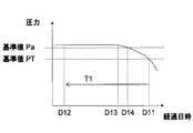
- FIG. 3 is data obtained by digitizing a signal acquired from a sensor attached to a device (not shown) to be diagnosed by the abnormality diagnosis device 1, and is a diagram showing time-series data of pressure sensor values. It shows how the pressure changes with the passage of time. An abnormality occurs in the device around time D13, and the pressure sensor value is gradually decreased due to the abnormality.
- the time-series data primary diagnosis unit 121 takes in time-series data of pressure sensor values and carries out a diagnosis process. While continuing the diagnostic process, at time D11, the time-series data management unit 123 is notified of an abnormality of the device.
- the time-series data management unit 123 as time-series data relating to the primary diagnosis result, is time-series data with a preset time width T1 going back from time D11 as a base point, that is, pressure sensor values from time D12 to time D11.
- the series data is read out from the data holding unit 122, and is transmitted to the server-side diagnosis device 3 together with the diagnosis result (the abnormality determination result and the abnormality occurrence time) received from the time-series data primary diagnosis unit 121.
- the time-series data primary diagnosis unit 121 takes in time-series data of pressure sensor values (step s601), and takes in the time-series data taken in among the reference value information held in advance in the time-series data primary diagnosis unit 121.
- the reference value information corresponding to is read out (step s602).
- the reference value PT corresponding to the pressure sensor value is read out.
- the time-series data primary diagnosis unit 121 compares the time-series data of the pressure sensor value taken in with the reference value PT, and determines whether or not the pressure value is below the reference value PT (step s603).
- the normal state is treated as being equal to or higher than the reference value, the reference value differs depending on the sensor signal, and the normal range is also different. If the time-series data of the pressure sensor value taken in does not fall below the reference value PT, the device state is determined to be normal, and the process returns to step s601 and continues. If the time-series data of the pressure sensor value taken in is lower than the reference value PT, the device state is determined as abnormal, and the time-series data management is performed with the abnormality determination result and the abnormality occurrence time (here, time D11) as the primary diagnosis result. Output to the unit 123 (step s604).
- the server-side diagnostic device 3 receives the primary diagnostic result and the time-series data transmitted from the machine-side diagnostic device 2, and performs diagnosis using the time-series data received by the time-series data secondary diagnostic unit 131.
- the result of diagnosis by the time-series data secondary diagnostic unit 131 (hereinafter referred to as secondary diagnostic result) is the diagnostic result display unit 132 together with the primary diagnostic result transmitted from the machine side diagnostic device 2 and the diagnostic result comparison unit Output to 133.
- the time-series data secondary diagnostic unit 131 receives time-series data from the time-series data management unit 123 (step s701), and calculates an average value ⁇ and standard deviation ⁇ of the time-series data fetched (step s702).
- the time series data secondary diagnostic unit 131 compares the data values v0 to vN at each time.
- the determination of the abnormality occurrence time for example, a method is used in which normalized time-series data exceeding ⁇ 3 continuously appear, and the time when the number of consecutive times reaches a specified number is taken as the abnormality occurrence time.
- the abnormal occurrence timing is detected as D14 as shown in FIG.
- the time series data secondary diagnosis unit 131 compares the diagnosis result display unit 132 and the diagnosis result together with the primary diagnosis result received from the time series data management unit 123 as the abnormality diagnosis result and the abnormality occurrence time D14 as a secondary diagnosis result. Output to the unit 133.
- the diagnosis result comparison unit 133 compares the primary diagnosis result and the secondary diagnosis result received from the time-series data secondary diagnosis unit 131, and determines whether the abnormality determination results are identical or the abnormality occurrence times are identical. Determine if it is. Whether or not the abnormality occurrence timings coincide is determined based on whether the difference between the occurrence timings falls within a predetermined period.
- the diagnosis result comparison unit 133 outputs the comparison result to the diagnosis result display unit 132.
- the diagnosis result comparison unit 133 reads the time series data from time D12 to time D14 from the time series data secondary diagnosis unit 131, and The lower limit value of the data is calculated as a new reference value Pa, and is output to the diagnostic setting update unit 134 as diagnostic setting change instruction information, and the diagnostic setting update unit 134 outputs the diagnostic setting change instruction information as time series data primary It is transmitted to the diagnosis unit 121.
- the time-series data primary diagnosis unit 121 sets a reference value Pa included in the received diagnostic setting change instruction information as a new reference value.
- the time-series data primary diagnosis unit 121 executes the diagnosis procedure of the machine-side diagnostic device 2 and the primary diagnosis result performed by the diagnosis result comparison unit 133 of the server-side diagnostic device 3 It may be configured to repeat until the comparison processing of the secondary diagnosis results in agreement. Further, the diagnosis result comparison unit 133 outputs diagnosis setting change instruction information to the diagnosis result display unit 132.
- the diagnosis result display unit 132 displays each information output from the time series data secondary diagnosis unit 131 and the diagnosis result comparison unit 133 on a monitor (not shown) and presents it to a user, for example, a manager (not shown). Do.
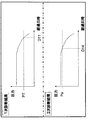
- FIG. 9 is a view showing a display example of a primary diagnosis result (first diagnosis result) and a secondary diagnosis result (second diagnosis result) output by the time-series data secondary diagnosis unit 131.
- the diagnosis result display unit 132 displays the secondary diagnosis result side by side with the primary diagnosis result.
- FIG. 10 is a diagram showing a display example of the comparison result of the primary diagnosis result and the secondary diagnosis result output by the diagnosis result comparison unit 133. As shown in FIG. In the display example of FIG. 10, the diagnostic result display unit 132 displays “pressure difference” of the determination reference value and “day difference” of the abnormality detection date as comparison information of the primary diagnosis result and the secondary diagnosis result. There is.
- FIG. 10 is a diagram showing a display example of the comparison result of the primary diagnosis result and the secondary diagnosis result output by the diagnosis result comparison unit 133.
- the diagnostic result display unit 132 displays “pressure difference” of the determination reference value and “day difference” of the abnormality detection date as comparison information of the primary diagnosis result and the secondary diagnosis result. There is.
- FIG. 11 is a diagram showing a display example of diagnostic setting change instruction information output by the diagnostic result comparison unit 133. As shown in FIG. In the display example of FIG. 11, the diagnostic result display unit 132 displays that the determination reference value of the sensor value has been changed from PT to Pa. It is preferable that the diagnostic setting value change instruction information be displayed together with the comparison result of the primary diagnosis result and the secondary diagnosis result shown in FIG.
- FIG. 12 shows a display example in the case where the administrator gives an instruction to permit the change of the diagnostic processing
- the screen 1101 is a display example for permitting the change of the judgment reference value
- the screen 1102 permits the rewriting of the whole diagnostic program. It is a display example to do.
- the diagnostic result comparison unit 133 outputs the diagnostic setting change instruction information via the diagnostic setting update unit 134
- the administrator confirms the setting change, and setting Update reliability is increased.
- the entire diagnostic program may be rewritten.
- the administrator can confirm the change of the diagnostic program and the reliability of the diagnostic program update is Increase.
- the abnormality diagnosis device 1 since the abnormality diagnosis device 1 is configured by the machine-side diagnosis device 2 and the server-side diagnosis device 3 and is multiplexed, the computer disposed on the machine side does not have sufficient processing capability. Even in this case, diagnostic accuracy can be improved.
- the machine-side diagnostic device 2 extracts time-series data related to the first diagnostic result and outputs the time-series data to the server-side diagnostic device 3, the communication data amount can be reduced and the communication capacity can be reduced.
- the diagnosis result display unit 132 displays the comparison result comparing both and further displays the update information of the diagnosis setting information, so that the diagnosis result or diagnosis by a human being It becomes possible to check the update status of the information.
- the diagnosis result display unit 132 displays the comparison result comparing both and further displays the update information of the diagnosis setting information, so that the diagnosis result or diagnosis by a human being It becomes possible to check the update status of the information.
- the primary diagnostic result is used as reference information to estimate the cause of the abnormality or the necessity or timing of maintenance / repair
- preventive maintenance measures can be considered, and reliable maintenance management and preventive maintenance can be performed.
- the diagnosis algorithm itself can be improved to perform more appropriate diagnosis, thereby further improving the diagnostic accuracy (see the second embodiment).
- the time series data secondary diagnosis unit 131 updates the diagnosis setting information of the time series data primary diagnosis unit 121 based on the comparison result of the primary diagnosis result and the secondary diagnosis result, whereby the time series data primary can be obtained. Since the diagnostic setting information of the diagnostic unit 121 is automatically updated, diagnostic accuracy can be improved also in this respect.
- Second Embodiment A second embodiment according to the present invention will be described with reference to FIG. 7 and FIGS. 1, 2 and 4 described above.
- the configuration, function, and operation of the abnormality diagnosis apparatus 1 of the present invention shown in FIGS. 1 and 2 are the same as the contents shown in the first embodiment, and thus will not be described.
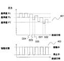
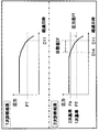
- FIG. 7 shows data obtained by digitizing a signal acquired from a sensor attached to a device (not shown) to be diagnosed by the abnormality diagnosis device 1, wherein time-series data 401 of pressure sensor values and the activation state of the device Is a diagram showing time-series data 402 of a signal indicating.
- the figure also shows that the pressure sensor value fluctuates along with the start and stop while repeating the start and stop as time passes.
- an abnormality occurs in the device around time D24, and the pressure sensor value gradually drops due to the abnormality.
- the time-series data primary diagnosis unit 121 takes in time-series data of pressure sensor values and carries out a diagnosis process.
- the time series data management unit 123 While continuing the diagnosis processing, at time D21 when the time series data of the pressure sensor value falls below the reference value PT, the time series data management unit 123 is notified of the abnormality of the device. However, thereafter, at time D22 when the time-series data of the pressure sensor value exceeds the reference value PT, the time-series data management unit 123 is notified of the normality of the device.
- the time-series data primary diagnosis unit 121 takes in time-series data of pressure sensor values (step s601), and takes in the time-series data taken in among the reference value information held in advance in the time-series data primary diagnosis unit 121.
- the reference value information corresponding to is read out (step s602).
- the reference value PT corresponding to the pressure sensor value is read out.
- the time-series data primary diagnosis unit 121 compares the time-series data of the pressure sensor value taken in with the reference value PT, and determines whether or not the pressure value is below the reference value PT (step s603).
- the normal state is treated as being equal to or higher than the reference value, the reference value differs depending on the sensor signal, and the normal range is also different. If the time-series data of the pressure sensor value taken in does not fall below the reference value PT, the device state is determined to be normal, and the process returns to step s601 and continues. If the time-series data of the pressure sensor value taken in is lower than the reference value PT, the device state is determined as abnormal, and time-series data management is performed with the abnormality determination result and the abnormality occurrence time (here, time D21) as the primary diagnosis result. Output to the unit 123 (step s604).
- the determination changes that the one determined as abnormal is normal.
- the anomaly detected once changes to normal and as a result, the server-side diagnostic device 3 is not notified of the diagnostic result of the abnormality occurrence state. It can happen. Alternatively, it may happen that the abnormal and normal states are repeatedly notified even though the abnormality actually continues. Even when the machine-side diagnostic device 2 notifies the server-side diagnostic device 3 as an abnormality, since the actual occurrence of the abnormality is time D24, it can be understood that the detection time of the abnormality is quite late.
- the reference value to be set is based on the pressure value at the time of stop and the place lower than that. Therefore, the difference from the actual pressure value at the time of start-up becomes large, and it becomes difficult to detect. If the reference value is based on the value at the time of start-up, there is a possibility that the pressure drop at the time of stop may be erroneously detected.
- the diagnosis processing using the normalization processing of time-series data performed by the time-series data secondary diagnosis unit 131 of the server-side diagnosis device 3 as described in the first embodiment is also possible. I can not detect normality and abnormality correctly. In the diagnosis processing using the normalization processing, since the reference value is set to Pb, an abnormality can be detected at time D23, but it is erroneously determined as a normal state again at time D25, and the abnormality continues. Regardless, it is not judged correctly.
- the administrator on the server side can grasp the diagnosis status as described above based on the display information of the diagnosis result display unit 132.
- the administrator on the server side improves the time-series data secondary diagnostic unit 131 of the server-side diagnostic device 3 and adds both the signal 401 indicating the pressure value and the signal 402 indicating the activation state to the pressure value.
- the diagnostic process (diagnostic program or diagnostic algorithm) of the time-series data primary diagnostic unit 121 of the machine-side diagnostic device 2 and the time-series data secondary diagnostic unit 131 of the server-side diagnostic device 3 is detected so that rewrite.
- the time-series data management unit 123 of the machine-side diagnostic device 2 adds the time-series data 401 of the pressure sensor value to the server-side diagnosis device together with the primary diagnosis result and the time-series data 402 of the signal indicating the activation state of the device. It will output to 3.
- the normalized value of the time-series data in the stopped state and the normalized value in the activated state are separately calculated, and the presence or absence of abnormality is determined by each normalized value. If both are determined to be abnormal, the diagnostic process is rewritten to determine that it is abnormal.
- Rewriting of the diagnostic processing (diagnostic algorithm) in the time-series data primary diagnostic unit 121 of the machine side diagnostic device 2 may be performed directly to the machine side diagnostic device 2, but in the case of this embodiment, the server side This is performed by the diagnostic setting update unit 134 of the diagnostic device 3.
- what the diagnosis setting update unit 134 transmits to the time series data primary diagnosis unit 121 is information of the new diagnosis processing itself that is determined using not only the new reference value but also a plurality of signals and the reference value. is there. Since the time-series data primary diagnostic unit 121 has means for updating itself in this way, not only new setting values but new diagnostic processing can be used. Can be further improved.
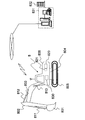
- FIG. 8 is a view showing an overall configuration of a large hydraulic excavator and an abnormality diagnosis device which are an example of an industrial machine to which the abnormality diagnosis device of the present invention is applied.
- the large hydraulic shovel 8 can perform operations such as excavation by each provided operation mechanism.
- the bucket 801, the arm 802 and the boom 803 constitute a working machine, which are driven by hydraulic cylinders 811, 812, 813.
- the hydraulic shovel 8 is provided with a swing body 806, a swing mechanism 804 for rotating the swing body 806, and left and right crawler (track) devices 805 (only one side is shown) as a travel mechanism of the entire hydraulic shovel.
- the turning mechanism 804 is provided with a turning hydraulic motor (not shown), and each crawler device 805 is provided with a traveling hydraulic motor.
- the revolving unit 806 is equipped with, for example, two engines 820 (only one is shown) and a plurality of main pumps 821 (only one shown) driven by these engines 820.
- the hydraulic cylinders 811 812 813 and hydraulic actuators such as hydraulic motors are driven by the discharge oil of the main pump 821.
- the hydraulic shovel 8 is mounted with a vehicle controller 830 for controlling each operation mechanism and collecting and monitoring information from sensors.
- the vehicle controller 830 has a communication function and communicates with the server 831.
- the server 831 is installed at a management office (for example, an office of a manufacturer, a dealer, a dealer, a rental company, etc. of the hydraulic shovel 1) 832.
- the machine-side diagnostic device 2 constituting the abnormality diagnosis device 1 of the present invention is incorporated in the vehicle body controller 830, and the server-side diagnostic device 3 is incorporated in the server 831. Further, in the present embodiment, the abnormality diagnosis device 1 diagnoses, for example, the main pump 821, and pressure sensors (not shown) for detecting the discharge pressure are attached to each of the main pump 821, so that the machine The side diagnostic device 2 takes in the signals output from those pressure sensors as time series data. In this case, since there are a plurality of main pumps 821, the machine-side diagnostic device 2 takes in time series data from the sensor for each pump and processes for each pump. Similarly, the server-side diagnostic device 3 takes in time-series data output from the machine-side diagnostic device 2 for each pump and processes it for each pump.
- the diagnosis target of the abnormality diagnosis device 1 may be the engine 820 or another device.
- 1 abnormality diagnosis device 2 machine side diagnosis device (first diagnosis device) 3 Server-side diagnostic device (second diagnostic device) 8 Large hydraulic excavator (industrial machine) 121 Time series data primary diagnosis unit (1st time series data diagnosis unit) 122 Data Holding Unit 123 Time Series Data Management Unit 131 Time Series Data Secondary Diagnosis Unit (Second Time Series Data Diagnosis Unit) 132 Diagnosis result display unit 133 Diagnosis result comparison unit 134 Diagnosis setting update unit 820 Engine (device) 821 Main pump (equipment) 830 Body controller 831 server
Abstract
センサが発生させる時系列データに基づいて機械または機器の状態診断を行うに当たって、機械側に配置された計算機が十分な処理能力を持たない場合であっても、診断精度を向上できるとともに、通信データ量が減少し通信容量を低減することができる異常診断装置およびその異常診断装置を備えた産業機械を提供する。機械側診断装置(2)は、センサが発生させる時系列データを診断して1次診断結果を取得し、かつその一次診断結果に関連する時系列データを抽出して一次診断結果とともにサーバ側診断装置(3)に出力し、サーバ側診断装置(3)は、その時系列データを診断して2次診断結果を取得し、2次診断結果を1次診断結果とともに表示する。また、それらの診断結果を比較し、比較結果が異なる場合は機械側診断装置(2)の診断処理を更新する。
Description
本発明は、機械または機器に取り付けて機械または機器の状態を診断する異常診断装置およびその異常診断装置を備えた産業機械に関する。
産業機械には、1日24時間ほとんど停止することなく365日連続稼動することが要求されるものがある。そのような産業機械として、例えば、鉱山等で稼動する大型油圧ショベル等の作業機械やプラントなどがある。このような産業機械(以下、適宜、単に機械という)は、故障などによって停止した場合に影響が大きいため、故障停止することがないように、保守によって機械或いは機械の一部(コンポーネント部分)である各種機器を最適な状態にするなどの措置が取られている。
保守は時間を基準にした定期保守(時間基準保守)が一般的である一方で、近年では機械または機器の状態に応じて保守を実施する状態基準保守が注目されている。定期保守は経過時間あるいは機械または機器の稼働時間などに基づいて点検や保守を行うスケジュールを決定する。一方、状態基準保守はセンサなどの計測データによって得られた情報を計算機によって処理し、予め定められた基準値に達しているかによって機械または機器の状態を把握し、把握した状態に基づいて点検や保守のスケジュールを決定する。保守と関連する機器の異常検知は、機械側に備わった制御コントローラなどによって実施され、制御コントローラは機械または機器の故障またはその直前にアラームを発報する。
状態基準保守は、時間基準保守と比較して点検や保守作業が効率的になる。しかし、計測データに基づく診断処理の性能によって保守作業効率が左右され、特に上述の診断処理のための基準値の設定が難しいとされている。そこで、診断性能を向上するために、より高度な診断判定を行うためのアルゴリズムを活用しようとする動きがある。
また、機器の診断装置を開示するものとして特許文献1~3がある。特許文献1には、機器の異常状態を検知し、それに応じて転送するデータの圧縮量を変更するという技術が開示されている。特許文献2には、診断装置の基準データを更新する技術が開示されている。特許文献3には、機械側の組込み診断装置に対して、診断に必要な診断モデルを更新する技術が開示されている。
制御コントローラなどの機械側に配置された計算機はCPUやメモリなどのリソースの制約から複雑な診断アルゴリズムを搭載することは難しい。一方で、例えば閾値判定などの簡易的な診断アルゴリズムでは、実際には設計想定時と異なる動作条件で機器が用いられるなどの理由で、誤報が発生する。より正確な診断を行うには複雑なアルゴリズムを実行する必要があるが、これは、管理事務所に配置されたサーバなどのCPUやメモリのリソースに余裕のある計算機でしか行えず、そのためには機械側に配置された制御コントローラからセンサデータをネットワークなどを経由して直接サーバまで送信する必要がある。しかし、機械側の制御コントローラからすべてのセンサデータを直接サーバに送信するには、通信やストレージの容量やコストに課題が生じるため、何らかの対策を講じる必要があった。
特許文献1では、機器の異常状態を検知し、それに応じて転送するデータの圧縮量を変更している。しかし、その技術を用いても、診断の性能の良否によってデータの圧縮量が変わるため、制御コントローラなどの機械側に配置された計算機で実施される精度の良くない診断では、データ量を十分に削減することができない可能性がある。
特許文献2では、診断装置の基準データを更新しているが、基準データの更新の根拠となるものが品質の検査結果であるため、自動化が難しいなどの課題がある。
特許文献3では、機械側の組込み診断装置に対して、診断に必要な診断モデルを更新している。しかし、引用文献3には、診断モデルの修正方法や修正に必要となる診断ミスの情報を得る手法についての開示がなされていない。
本発明は、このような課題に鑑みてなされたもので、その目的は、機械または機器に取り付けられたセンサが発生させる時系列データに基づいて機械または機器の状態診断を行うに当たって、機械側に配置された計算機が十分な処理能力を持たない場合であっても、診断精度を向上させることができるとともに、通信データ量が減少し通信容量を低減することができる異常診断装置およびその異常診断装置を備えた産業機械を提供することにある。
上記課題を解決するため、本発明は、機械または機器に取り付けられたセンサが発生させる時系列データに基づいて前記機械または機器の状態診断を行う異常診断装置において、前記機械側の計算機に組み込まれた第1診断装置と、前記第1診断装置と通信を行うサーバに組み込まれた第2診断装置とを備え、前記第1診断装置は、前記センサが発生させる時系列データを診断して第1診断結果を取得し、その第1診断結果に応じて、前記第1診断結果に関連する時系列データを抽出して、前記第1診断結果に関連する時系列データを前記第1診断結果とともに出力し、前記第2診断装置は、前記第1診断装置から前記第1診断結果と前記第1診断結果に関連する時系列データを受け取り、この時系列データを診断して第2診断結果を取得し、その第2診断結果を前記第1診断結果とともに出力するものとする。
このように異常診断装置を、機械側の計算機に組み込まれた第1診断装置とサーバ側に組み込まれた第2診断装置とで構成して多重化したことにより、機械側に配置された計算機が十分な処理能力を持たない場合であっても、診断精度を向上させることができる。また、機械側の計算機に組み込まれた第1診断装置は、第1診断結果に関連する時系列データを抽出してサーバ側の第2診断装置に出力するため、通信データ量が減少し通信容量を削減することができる。
好ましくは、前記第2診断装置は、前記第2診断結果を前記第1診断結果と比較し、その比較結果を前記第1診断結果及び前記第2診断結果とともに出力する。
また、好ましくは、前記第2診断装置は、前記第2診断結果を前記第1の診断結果と比較し、その比較結果に基づいて前記第1診断装置の診断情報を更新する。
また、好ましくは、前記第2診断装置は、前記第1診断結果及び前記第2診断結果を表示部に表示する。その場合、前記第1診断結果及び前記第2診断結果と前記比較結果かつ/または前記診断情報の更新に係わる情報とともに表示部に表示する。
このように第1および第2診断結果に加えて、第2診断結果を第1診断結果と比較した比較結果を出力したり、その比較結果かつ/または診断情報の更新に係わる情報を表示部に表示することにより、人間による診断結果や診断情報の更新状態の確認が可能となる。また、第1診断結果と第2診断結果を比較した結果、両者が一致しない場合は、第1診断結果を参考情報として用いて、異常の原因を推定したり、保守修理の必要性或いは時期等、更には予防保全対策を検討することができ、信頼性の高い保守管理と予防保全を行うことができる。更には、第1診断結果と第2診断結果の時間的遷移を監視し、第1および第2診断装置が用いる診断アルゴリズムが診断に適切であるかどうかを判断することができ、適切でない場合は診断アルゴリズムそのものを改良し、より適切な診断を行えるようにすることで、更なる診断精度の向上を図ることができる。
また、第2診断装置が、第2診断結果と第1の診断結果の比較結果に基づいて第1診断装置の診断情報を更新することで、第1診断装置の診断情報が自動で更新されるため、この点でも診断精度を向上することができる。
本発明によれば、機械または機器に取り付けられたセンサが発生させる時系列データに基づいて機器の状態診断を行うに当たって、機械側に配置された計算機が十分な処理能力を持たない場合であっても、診断精度を向上させ、機器の予防保全に寄与することができる。また、通信データ量が減少し通信容量を削減することができる。
<第1の実施の形態>
本発明に係わる第1の実施の形態について図1~図5を用いて説明する。
本発明に係わる第1の実施の形態について図1~図5を用いて説明する。
図1は、本発明の異常診断装置の構成を示す図である。異常診断装置1は、機械側の計算機に組み込まれた機械側診断装置2(第1診断装置)とサーバに組み込まれたサーバ側診断装置3(第2診断装置)とで構成される。機械側診断装置2は、時系列データ1次診断部121(第1時系列データ診断部)とデータ保持部122と時系列データ管理部123とで構成される。サーバ側診断装置3は、時系列データ2次診断部131(第2時系列データ診断部)と診断結果表示部132と診断結果比較部133と診断設定更新部134とで構成される。
図2は、機械側診断装置2とサーバ側診断装置3の機能と動作を示すフローチャートである。
機械側診断装置2には、機器から出力されたセンサ信号などの時系列データが入力され、入力された時系列データは、時系列データ1次診断部121とデータ保持部122に入力される。時系列データ1次診断部121は受け取った時系列データを診断し、機器の状態が正常であるか異常であるかを判定する。判定した結果は、1次診断結果(第1診断結果)としてデータ保持部122と時系列データ管理部123に出力される(ステップs201)。データ保持部122は、機器から受け取った時系列データと時系列データ1次診断部121から受け取った1次診断結果を保持する(ステップs202)。このとき、データ保持部122は、データ保持部122が受け取った時系列データおよび1次診断結果のすべてを保持しても良いが、好ましくはそれらのデータの全てを一時的に保持した後、時系列データ管理部123の読み出しデータに対応するデータのみを保持する。時系列データ管理部123は、時系列データ1次診断部121から受け取った1次診断結果が機器の異常を示すものであるときは、データ保持部122が保持している1次診断結果に関する時系列データを読み出して、1次診断結果とともにサーバ側診断装置3に出力する(ステップs203)。
サーバ側診断装置3では、時系列データ2次診断部131が機械側診断装置2から受け取った1次診断結果およびそれに関する時系列データを受け取り、受け取った時系列データを診断し、機器の状態が正常であるか異常であるかを判定する(ステップs204)。判定した結果は、2次診断結果(第2診断結果)として1次診断結果とともに診断結果表示部132と診断結果比較部133に出力する。診断結果比較部133では、受け取った1次診断結果と2次診断結果を比較し(ステップs205)、比較結果を診断結果表示部132に出力する(ステップs207)。比較結果が1次診断結果と2次診断結果が異なる場合には(ステップs206)、診断結果比較部133は診断設定更新部134に診断設定変更指示情報を出力し、診断設定更新部134はその診断設定変更指示情報を時系列データ1次診断部121に出力する。時系列データ1次診断部121はその診断設定変更指示情報を受け取ると、時系列データ1次診断部121の設定情報を変更する(ステップs208)。また、診断結果比較部133は診断結果表示部132に診断設定変更指示情報を出力する。診断結果表示部132は、2次診断結果(第2診断結果)を1次診断結果(第1診断結果)と並べて表示する。また、1次診断結果と2次診断結果の比較結果と診断設定変更指示情報を合わせて表示する。
機械側診断装置2とサーバ側診断装置3の機能と動作を、数値化した時系列データを用いて、図3~図6により更に詳細に説明する。
図3は、異常診断装置1がその診断対象とする機器(図示なし)に取り付けらたセンサから取り込んだ信号を数値化したデータであって、圧力センサ値の時系列データを示す図である。時間経過に伴って圧力が変化している様子を示している。時刻D13付近で機器に異常が発生し、その異常によって圧力センサ値が徐々に降下している状況を表している。機械側診断装置2において、時系列データ1次診断部121は、圧力センサ値の時系列データを取り込み、診断処理を実施する。診断処理を継続している中で、時刻D11時点で、時系列データ管理部123に機器の異常が通知される。時系列データ管理部123は、1次診断結果に関する時系列データとして、時刻D11を基点として予め設定された時間幅T1分遡った時系列データ、すなわち時刻D12から時刻D11までの圧力センサ値の時系列データを、データ保持部122から読み出すとともに、時系列データ1次診断部121から受け取った診断結果(異常判定結果および異常発生時期)とともに、サーバ側診断装置3に送信する。
時系列データ1次診断部121における上述の診断処理は、図4に示すようなフローで実施される。まず、時系列データ1次診断部121は圧力センサ値の時系列データを取り込み(ステップs601)、予め時系列データ1次診断部121に保持している基準値情報のうち、取り込んだ時系列データに対応した基準値情報を読み出す(ステップs602)。この場合、圧力センサ値に対応した基準値PTを読み出す。時系列データ1次診断部121は、取り込んだ圧力センサ値の時系列データと基準値PTを比較し、基準値PTを下回っていないかを判定する(ステップs603)。本実施の形態では基準値以上であることを正常状態として扱うが、センサ信号によって基準値は異なり、またその正常範囲も異なる。取り込んだ圧力センサ値の時系列データが基準値PTを下回っていなければ、機器状態を正常と判定し、ステップs601に戻って処理を継続する。取り込んだ圧力センサ値の時系列データが基準値PTを下回っていれば、機器状態を異常と判定し、異常判定結果および異常発生時期(ここでは時刻D11)を1次診断結果として時系列データ管理部123に出力する(ステップs604)。
次に、サーバ側診断装置3は、機械側診断装置2から送信された1次診断結果および時系列データを受け取り、時系列データ2次診断部131が受け取った時系列データを用いて診断を行う。時系列データ2次診断部131が診断した結果(これを以下2次診断結果と呼ぶ)は、機械側診断装置2から送信された1次診断結果とともに診断結果表示部132、および診断結果比較部133に出力する。
ここで時系列データ2次診断部131が行う診断処理は、図5に示すようなフローで実施される。時系列データ2次診断部131は時系列データ管理部123から時系列データを受け取り(ステップs701)、取り込んだ時系列データの平均値μおよび標準偏差σを算出する(ステップs702)。次に、時系列データが図6のようであったとすると(各時刻t0 ~tNは等間隔であったとすると)、時系列データ2次診断部131は各時刻のデータ値v0 ~vNに対して正規化値Ui(i=0~N)を、平均値μおよび標準偏差σにより(式1)を用いて計算する(ステップs703)。

続いて、この各時刻の正規化された時系列データUi(i=0~N)が±3を超えるものを異常と判定し(ステップs704)、これにより異常発生時期を決定する。異常発生時期の判定は、例えば正規化された時系列データが±3を超えるものが連続して出現し、その連続数が規定回数に達した時点を異常発生時期とするなどの方法を用いる。ここでは、上記方法によって異常であるという判定結果を得て、異常発生時期が図3に示すようなD14として検出されたとする。時系列データ2次診断部131は、これら異常判定結果と異常発生時期D14とを2次診断結果として時系列データ管理部123から受け取った1次診断結果とともに、診断結果表示部132および診断結果比較部133に出力する。
次に、診断結果比較部133は、時系列データ2次診断部131から受け取った1次診断結果および2次診断結果を比較し、異常判定結果が一致しているか、また異常発生時期が一致しているかを判定する。異常発生時期が一致しているかは、発生時期の差が予め定められた期間内に収まっているかで判定する。診断結果比較部133は、比較結果を診断結果表示部132に出力する。
また、1次診断結果と2次診断結果を比較して異なっている場合、診断結果比較部133は、時系列データ2次診断部131から時刻D12から時刻D14までの時系列データを読み出し、そのデータの下限値を新たな基準値Paをとして算出し、これを診断設定変更指示情報として診断設定更新部134に出力し、診断設定更新部134はその診断設定変更指示情報を時系列データ1次診断部121に送信する。時系列データ1次診断部121では、受け取った診断設定変更指示情報に含まれる基準値Paを新たな基準値として設定する。基準値が変更された場合に、時系列データ1次診断部121は、機械側診断装置2の診断手順を実施し、サーバ側診断装置3の診断結果比較部133にて行う1次診断結果と2次診断結果の比較処理が一致するまで繰り返すように構成してもよい。また、診断結果比較部133は診断結果表示部132に診断設定変更指示情報を出力する。
診断結果表示部132は、時系列データ2次診断部131および診断結果比較部133が出力する各情報をモニタ(図示せず)に表示して、利用者、例えば管理者(図示なし)に提示する。
図9は、時系列データ2次診断部131が出力する1次診断結果(第1診断結果)と2次診断結果(第2診断結果)の表示例を示す図である。この図9の表示例では、診断結果表示部132は、2次診断結果を1次診断結果と並べて表示している。図10は、診断結果比較部133が出力する1次診断結果と2次診断結果の比較結果の表示例を示す図である。この図10の表示例では、診断結果表示部132は、1次診断結果と2次診断結果の比較情報として、判定基準値の「圧力差」と異常検出日の「日数差」を表示している。図11は、診断結果比較部133が出力する診断設定変更指示情報の表示例を示す図である。この図11の表示例では、診断結果表示部132はセンサ値の判定基準値をPTからPaに変更したことを表示している。この診断設定値変更指示情報は、図10に示す1次診断結果と2次診断結果の比較結果と合わせて表示することが好ましい。
図12は、管理者が診断処理の変更を許可する指示を与える場合の表示例であり、画面1101は判定基準値の変更を許可するための表示例、画面1102は診断プログラム全体の書き換えを許可するための表示例である。診断結果比較部133が診断設定更新部134を介して診断設定変更指示情報を出力する場合、その出力前に画面1101を表示することで、設定の変更を管理者に確認させることができ、設定更新の信頼性が高まる。後述する如く、診断プログラム全体を書き換えてもよく、その場合も、その出力前に画面1102を表示することで、診断プログラムの変更を管理者に確認させることができ、診断プログラム更新の信頼性が高まる。
本実施の形態によれば、異常診断装置1を、機械側診断装置2とサーバ側診断装置3とで構成して多重化したため、機械側に配置された計算機が十分な処理能力を持たない場合であっても、診断精度を向上させることができる。また、機械側診断装置2は、第1診断結果に関連する時系列データを抽出してサーバ側診断装置3に出力するため、通信データ量が減少し、通信容量を削減することができる。
また、診断結果表示部132に1次診断結果および2次診断結果に加えて、両者を比較した比較結果を表示し、更には診断設定情報の更新情報を表示するため、人間による診断結果や診断情報の更新状態の確認が可能となる。また、1次診断結果と2次診断結果を比較した結果、両者が一致しない場合は、1次診断結果を参考情報として用いることで、異常の原因を推定したり、保守修理の必要性或いは時期等、更には予防保全対策を検討することができ、信頼性の高い保守管理と予防保全を行うことができる。更には、1次診断結果と2次診断結果の時間的遷移を監視し、時系列データ1次診断部121および時系列データ2次診断部131が用いる診断アルゴリズムが診断に適切であるかどうかを判断することができ、適切でない場合は診断アルゴリズムそのものを改良し、より適切な診断を行えるようにすることで、更なる診断精度の向上を図ることができる(第2の実施の形態参照)。
また、時系列データ2次診断部131が、1次診断結果と2次診断結果の比較結果に基づいて時系列データ1次診断部121の診断設定情報を更新することで、時系列データ1次診断部121の診断設定情報を自動で更新されるため、この点でも診断精度を向上することができる。
<第2の実施の形態>
本発明に係わる第2の実施の形態について、図7と、先の図1、図2および図4を用いて説明する。図1および図2に示した本発明の異常診断装置1の構成と機能および動作については、第1の実施の形態に示した内容と同じであるので、省略する。
<第2の実施の形態>
本発明に係わる第2の実施の形態について、図7と、先の図1、図2および図4を用いて説明する。図1および図2に示した本発明の異常診断装置1の構成と機能および動作については、第1の実施の形態に示した内容と同じであるので、省略する。
以下、本実施の形態の機能と動作の詳細について説明する。図7は、異常診断装置1がその診断対象とする機器(図示なし)に取り付けられたセンサから取り込んだ信号を数値化したデータであって、圧力センサ値の時系列データ401と機器の起動状態を示す信号の時系列データ402を示す図である。時間経過に伴って起動と停止を繰り返しながら、その起動と停止に伴って圧力センサ値も変動している様子を示している。この実施の形態では、時刻D24付近で機器に異常が発生し、その異常によって圧力センサ値が徐々に降下している状況を表している。機械側診断装置2において、時系列データ1次診断部121は、圧力センサ値の時系列データを取り込み、診断処理を実施する。診断処理を継続している中で、圧力センサ値の時系列データが基準値PTを下回った時刻D21時点で、時系列データ管理部123に機器の異常が通知される。しかし、その後、圧力センサ値の時系列データが基準値PTを上回った時刻D22時点で、時系列データ管理部123に機器の正常が通知される。
時系列データ1次診断部121における上述の診断処理は、第1の実施の形態と同様に図4に示すフローで実施される。まず、時系列データ1次診断部121は圧力センサ値の時系列データを取り込み(ステップs601)、予め時系列データ1次診断部121に保持している基準値情報のうち、取り込んだ時系列データに対応した基準値情報を読み出す(ステップs602)。この場合、圧力センサ値に対応した基準値PTを読み出す。時系列データ1次診断部121は、取り込んだ圧力センサ値の時系列データと基準値PTを比較し、基準値PTを下回っていないかを判定する(ステップs603)。本実施の形態では基準値以上であることを正常状態として扱うが、センサ信号によって基準値は異なり、またその正常範囲も異なる。取り込んだ圧力センサ値の時系列データが基準値PTを下回っていなければ、機器状態を正常と判定し、ステップs601に戻って処理を継続する。取り込んだ圧力センサ値の時系列データが基準値PTを下回っていれば、機器状態を異常と判定し、異常判定結果および異常発生時期(ここでは時刻D21)を1次診断結果として時系列データ管理部123に出力する(ステップs604)。
しかしながら、上述のように、時刻がD22に達すると、一度異常として判定されたものが、正常になったと判定が変化する。機械側診断装置2がサーバ側診断装置3に通知するタイミングによっては、一度検知された異常が正常に変化するため、結果としてサーバ側診断装置3に異常発生状態の診断結果が通知されないということが起こりうる。あるいは、実際には異常が継続しているにも関わらず、異常と正常の状態が繰り返し通知されるということが起こりうる。異常として機械側診断装置2がサーバ側診断装置3に通知した場合にも、実際の異常発生は時刻D24であるので、異常の検知時期がかなり遅いことが分かる。これは、正常状態での運転期間(ここでは時刻D24までの期間)においても、起動と停止が繰り返され、起動や停止の状態に応じて圧力値が変化するため、圧力値の異常低下を検知するための基準値を停止時の圧力値を基準に、それよりも低いところを基準とするためである。そのため、起動時の実際の圧力値との差異が大きくなり、検知しにくくなるためである。もし基準値を起動時にあわせた値をもとにすれば、停止時の圧力低下を誤検知する可能性が出てしまう。
本実施の形態のような場合、第1の実施の形態で示したようなサーバ側診断装置3の時系列データ2次診断部131が行う時系列データの正規化処理を用いた診断処理によっても正しく正常と異常を検知できない。正規化処理を用いた診断処理では、基準値がPbに設定されるため、時刻D23において異常を検知できるようになるが、時刻D25において再び正常状態として誤判定され、異常が継続しているにも関わらず、正しく判定されない。
サーバ側の管理者は、診断結果表示部132の表示情報に基づいて上記のような診断状況を把握することができる。
そこで、サーバ側の管理者は、サーバ側診断装置3の時系列データ2次診断部131を改良し、圧力値を示す信号401と起動状態を示す信号402の両方を加味した上で、圧力値の異常低下が検知されるように、機械側診断装置2の時系列データ1次診断部121およびサーバ側診断装置3の時系列データ2次診断部131の診断処理(診断プログラム或いは診断アルゴリズム)を書き換える。具体的には、時系列データ1次診断部121の診断処理においては、圧力センサ値の時系列データ401に加えて機器の起動状態を示す信号の時系列データ402を取り込み、停止状態においては基準値Pbを用い、起動状態においては基準値Pcを用いて判定するように診断処理を書き換える。このように変更することで、時刻D24を境として、常に異常として正しく判定されるようになる。このとき、機械側診断装置2の時系列データ管理部123においては、圧力センサ値の時系列データ401に加えて機器の起動状態を示す信号の時系列データ402を一次診断結果とともにサーバ側診断装置3に出力するようになる。また、時系列データ2次診断部131の診断処理においては、停止状態における時系列データの正規化値と起動状態における正規化値を別々に計算し、それぞれの正規化値で異常の有無を判定し、両方で異常有りと判定された場合に、異常と判定するように診断処理を書き換える。
機械側診断装置2の時系列データ1次診断部121にける診断処理(診断アルゴリズム)の書き換えは、機械側診断装置2に対して直接行ってもよいが、本実施の形態の場合、サーバ側診断装置3の診断設定更新部134が行う。その場合、診断設定更新部134が時系列データ1次診断部121に送信するのは、新たな基準値だけではなく、複数の信号と基準値を用いて判定するという新しい診断処理そのものの情報である。このように時系列データ1次診断部121が自分自身を更新する手段を持つことで、新たな設定値だけではなく、新たな診断処理を用いることができるようになるため、機器側における診断精度を更に向上させることが可能になる。
<第3の実施の形態>
次に、本発明の異常診断装置の適用例を図8を用いて説明する。図8は、本発明の異常診断装置が適用される産業機械の一例である大型油圧ショベルの全体構成と異常診断装置を示す図である。
<第3の実施の形態>
次に、本発明の異常診断装置の適用例を図8を用いて説明する。図8は、本発明の異常診断装置が適用される産業機械の一例である大型油圧ショベルの全体構成と異常診断装置を示す図である。
大型油圧ショベル8は、備えられた各操作機構によって掘削などの動作を行うことができる。バケット801、アーム802、ブーム803は作業機を構成し、これらは油圧シリンダ811,812,813によって駆動される。また、油圧ショベル8には、旋回体806と、旋回体806を回転させる旋回機構804と、油圧ショベル全体の走行機構としての左右のクローラー(履帯)装置805(片側のみ図示)が備わっている。旋回機構804は旋回用の油圧モータ(図示せず)を備え、クローラー装置805は、それぞれ、走行用の油圧モータを備えている。旋回体806には例えば2台のエンジン820(1台のみ図示)とこれらのエンジン820で駆動される複数台のメインポンプ821(1台のみ図示)が装備されている。油圧シリンダ811,812,813や油圧モータ等の油圧アクチュエータはメインポンプ821の吐出油により駆動される。
また、油圧ショベル8には、各操作機構を制御し、かつセンサからの情報を収集・監視するための車体コントローラ830が搭載されている。車体コントローラ830は通信機能を有し、サーバ831と通信を行う。サーバ831は管理事務所(例えば油圧ショベル1のメーカ、販売店、ディーラ、レンタル業者等の事務所)832に設置されている。
本発明の異常診断装置1を構成する機械側診断装置2は車体コントローラ830に組み込まれ、サーバ側診断装置3はサーバ831に組み込まれている。また、本実施の形態では、異常診断装置1は、例えば、メインポンプ821の診断を行うものであり、メインポンプ821のそれぞれに吐出圧を検出する圧力センサ(図示せず)が取り付けられ、機械側診断装置2は、それらの圧力センサが出力する信号を時系列データとして取り込む。この場合、メインポンプ821は複数台あるため、機械側診断装置2はセンサからの時系列データをポンプ毎に取り込んでポンプ毎に処理する。サーバ側診断装置3も、同様に、機械側診断装置2から出力された時系列データをポンプ毎に取り込んでポンプ毎に処理する。
なお、異常診断装置1の診断対象はエンジン820、その他の機器であってもよい。
1 異常診断装置
2 機械側診断装置(第1診断装置)
3 サーバ側診断装置(第2診断装置)
8 大型油圧ショベル(産業機械)
121 時系列データ1次診断部(第1時系列データ診断部)
122 データ保持部
123 時系列データ管理部
131 時系列データ2次診断部(第2時系列データ診断部)
132 診断結果表示部
133 診断結果比較部
134 診断設定更新部
820 エンジン(機器)
821 メインポンプ(機器)
830 車体コントローラ
831 サーバ
2 機械側診断装置(第1診断装置)
3 サーバ側診断装置(第2診断装置)
8 大型油圧ショベル(産業機械)
121 時系列データ1次診断部(第1時系列データ診断部)
122 データ保持部
123 時系列データ管理部
131 時系列データ2次診断部(第2時系列データ診断部)
132 診断結果表示部
133 診断結果比較部
134 診断設定更新部
820 エンジン(機器)
821 メインポンプ(機器)
830 車体コントローラ
831 サーバ
Claims (11)
- 機械または機器に取り付けられたセンサが発生させる時系列データに基づいて前記機械または機器の状態診断を行う異常診断装置において、
前記機械側の計算機に組み込まれた第1診断装置と、
前記第1診断装置と通信を行うサーバに組み込まれた第2診断装置とを備え、
前記第1診断装置は、前記センサが発生させる時系列データを診断して第1診断結果を取得し、その第1診断結果に応じて、前記第1診断結果に関連する時系列データを抽出して、前記第1診断結果に関連する時系列データを前記第1診断結果とともに出力し、
前記第2診断装置は、前記第1診断装置から前記第1診断結果と前記第1診断結果に関連する時系列データを受け取り、この時系列データを診断して第2診断結果を取得し、その第2診断結果を前記第1診断結果とともに出力することを特徴とする異常診断装置。 - 請求項1記載の異常診断装置において、
前記第2診断装置は、前記第2診断結果を前記第1診断結果と比較し、その比較結果を前記第1診断結果及び前記第2診断結果とともに出力することを特徴とする異常診断装置。 - 請求項1記載の異常診断装置において、
前記第2診断装置は、前記第2診断結果を前記第1診断結果と比較し、その比較結果に基づいて前記第1診断装置の診断情報を更新することを特徴とする異常診断装置。 - 請求項1記載の異常診断装置において、
前記第2診断装置は、前記第1診断結果及び前記第2診断結果を表示部に表示することを特徴とする異常診断装置。 - 請求項2記載の異常診断装置において、
前記第2診断装置は、前記第1診断結果及び前記第2診断結果と前記比較結果を表示部に表示することを特徴とする異常診断装置。 - 請求項3記載の異常診断装置において、
前記第2診断装置は、前記第1診断結果及び前記第2診断結果と前記診断情報の更新に係わる情報を表示部に表示することを特徴とする異常診断装置。 - 請求項1記載の異常診断装置において、
前記第1診断装置は、
前記センサが発生させる時系列データを診断して前記第1診断結果を出力する第1時系列データ診断部と、
前記センサが発生させる時系列データを保持するデータ保持部と、
前記第1時系列データ診断部が出力する前記第1診断結果に応じて、前記データ保持部から前記第1診断結果に関連する時系列データを読み出して、前記第1診断結果とともに出力する時系列データ管理部とを有することを特徴とする異常診断装置。 - 請求項1または7記載の異常診断装置において、
前記第2診断装置は、
前記第1診断装置から前記第1診断結果と前記第1診断結果に関連する時系列データを受け取り、この時系列データを診断して前記第2診断結果を出力する第2時系列データ診断部と、
前記第2時系列データ診断部が出力する前記第2診断結果を前記第1診断結果とともに表示する診断結果表示部とを有することを特徴とする異常診断装置。 - 請求項8記載の異常診断装置において、
前記第2診断装置は、
前記第2時系列データ診断部が出力する前記第2診断結果を前記第1の診断結果と比較する診断結果比較部を更に有し、
前記診断結果表示部は、前記診断結果比較部の比較結果を前記第1診断結果及び前記第2診断結果とともに表示することを特徴とする異常診断装置。 - 請求項8記載の異常診断装置において、
前記第2診断装置は、
前記第2時系列データ診断部が出力する前記第2診断結果を前記第1の診断結果と比較する診断結果比較部と、
前記診断結果比較部の比較結果に応じて前記第1時系列データ診断部の診断情報を更新する診断設定更新部とを更に有し、
前記診断結果表示部は、前記診断結果比較部の比較結果と前記診断設定更新部の前記診断情報の更新に係わる情報とを前記第1診断結果及び前記第2診断結果とともに表示することを特徴とする異常診断装置。 - 前記センサが取り付けられ、請求項1または7記載の第1診断装置を備えたことを特徴とする産業機械。
Priority Applications (3)
| Application Number | Priority Date | Filing Date | Title |
|---|---|---|---|
| CN201180052092.2A CN103180793B (zh) | 2010-10-28 | 2011-10-20 | 异常诊断装置以及工业机械 |
| EP11836137.7A EP2634660B1 (en) | 2010-10-28 | 2011-10-20 | Anomaly diagnostic device and industrial machine |
| US13/881,543 US9678845B2 (en) | 2010-10-28 | 2011-10-20 | Abnormality diagnostic system and industrial machinery |
Applications Claiming Priority (2)
| Application Number | Priority Date | Filing Date | Title |
|---|---|---|---|
| JP2010-242180 | 2010-10-28 | ||
| JP2010242180A JP5455866B2 (ja) | 2010-10-28 | 2010-10-28 | 異常診断装置および産業機械 |
Publications (1)
| Publication Number | Publication Date |
|---|---|
| WO2012057001A1 true WO2012057001A1 (ja) | 2012-05-03 |
Family
ID=45993713
Family Applications (1)
| Application Number | Title | Priority Date | Filing Date |
|---|---|---|---|
| PCT/JP2011/074218 WO2012057001A1 (ja) | 2010-10-28 | 2011-10-20 | 異常診断装置および産業機械 |
Country Status (5)
| Country | Link |
|---|---|
| US (1) | US9678845B2 (ja) |
| EP (1) | EP2634660B1 (ja) |
| JP (1) | JP5455866B2 (ja) |
| CN (1) | CN103180793B (ja) |
| WO (1) | WO2012057001A1 (ja) |
Cited By (3)
| Publication number | Priority date | Publication date | Assignee | Title |
|---|---|---|---|---|
| WO2014207789A1 (ja) * | 2013-06-24 | 2014-12-31 | 株式会社 日立製作所 | 状態監視装置 |
| AU2014200815B2 (en) * | 2013-02-20 | 2016-01-28 | Hitachi Construction Machinery Co., Ltd. | Condition monitoring system, condition monitoring system unit, and terminal system unit |
| CN108027611A (zh) * | 2015-09-18 | 2018-05-11 | 赛峰飞机发动机公司 | 利用受专家意见监督的决策模式学习的用于机器维护的决策辅助系统和方法 |
Families Citing this family (25)
| Publication number | Priority date | Publication date | Assignee | Title |
|---|---|---|---|---|
| JP5988740B2 (ja) * | 2012-07-13 | 2016-09-07 | 日立建機株式会社 | 稼働機械の保守管理装置 |
| JP5836222B2 (ja) * | 2012-08-14 | 2015-12-24 | 日立オートモティブシステムズ株式会社 | 車両制御装置および車両制御システム |
| JP2015084176A (ja) * | 2013-10-25 | 2015-04-30 | 日立建機株式会社 | 故障診断装置および稼働機械 |
| EP2887236A1 (en) * | 2013-12-23 | 2015-06-24 | D square N.V. | System and method for similarity search in process data |
| JP5863763B2 (ja) * | 2013-12-27 | 2016-02-17 | 三菱重工業株式会社 | 油圧機械の診断方法及び診断装置 |
| WO2015132838A1 (ja) * | 2014-03-03 | 2015-09-11 | 株式会社日立製作所 | 機械の材料疲労の表示方法、及びその装置 |
| JP6445859B2 (ja) * | 2014-12-16 | 2018-12-26 | 株式会社東芝 | プラント監視装置 |
| JP6705903B2 (ja) * | 2016-09-02 | 2020-06-03 | 株式会社日立製作所 | 診断装置、診断方法及び診断プログラム |
| US10430021B2 (en) * | 2016-10-05 | 2019-10-01 | Snap-On Incorporated | System and method for providing an interactive vehicle diagnostic display |
| JP6842299B2 (ja) * | 2016-12-28 | 2021-03-17 | 三菱パワー株式会社 | 診断装置、診断方法及びプログラム |
| WO2018135171A1 (ja) * | 2017-01-19 | 2018-07-26 | 株式会社日立製作所 | 保全管理システム及びそれに用いる保全管理確認装置 |
| JP6712354B2 (ja) * | 2017-02-24 | 2020-06-17 | 株式会社日立製作所 | 異常診断システム |
| JP6829158B2 (ja) * | 2017-07-18 | 2021-02-10 | 株式会社東芝 | データ処理装置、データ処理方法、およびプログラム |
| CN110096036A (zh) * | 2018-01-29 | 2019-08-06 | 阿里巴巴集团控股有限公司 | 一种设备状态的确定方法、装置及设备 |
| JP7074489B2 (ja) * | 2018-02-08 | 2022-05-24 | 株式会社Screenホールディングス | データ処理方法、データ処理装置、および、データ処理プログラム |
| JP7186518B2 (ja) * | 2018-06-05 | 2022-12-09 | 株式会社東芝 | 異常診断装置、異常診断システムおよび異常診断方法 |
| CN112334924A (zh) * | 2018-07-10 | 2021-02-05 | 住友重机械工业株式会社 | 施工机械的显示方法及施工机械的支持装置 |
| US11093314B2 (en) * | 2018-07-23 | 2021-08-17 | Mitsubishi Electric Corporation | Time-sequential data diagnosis device, additional learning method, and recording medium |
| DE102018121270B4 (de) | 2018-08-31 | 2023-12-21 | Volkswagen Aktiengesellschaft | Diagnoseverfahren, Diagnosesystem und Kraftfahrzeug |
| CN111340250A (zh) * | 2018-12-19 | 2020-06-26 | 富泰华工业(深圳)有限公司 | 设备检修装置、方法及计算机可读存储介质 |
| DE102019219727A1 (de) | 2018-12-26 | 2020-07-02 | Presenso Ltd. | System und Verfahren zum Detektieren von Anomalien in Sensordaten von industriellen Maschinen, die in einer vorbestimmten Umgebung angeordnet sind |
| JP6625280B1 (ja) * | 2018-12-27 | 2019-12-25 | 三菱電機株式会社 | 異常診断装置および異常診断方法 |
| JP7357450B2 (ja) * | 2019-02-28 | 2023-10-06 | コマツ産機株式会社 | 学習データを収集するためのシステム、及び方法 |
| CN112988501B (zh) * | 2019-12-17 | 2023-02-03 | 深信服科技股份有限公司 | 一种告警信息生成方法、装置、电子设备及存储介质 |
| KR102340395B1 (ko) * | 2020-01-02 | 2021-12-15 | 두산중공업 주식회사 | 플랜트의 고장을 진단하기 위한 장치 및 이를 위한 방법 |
Citations (5)
| Publication number | Priority date | Publication date | Assignee | Title |
|---|---|---|---|---|
| JP2002006942A (ja) * | 2000-06-22 | 2002-01-11 | Hitachi Ltd | 遠隔監視診断システム、及び遠隔監視診断方法 |
| JP2003015734A (ja) | 2001-07-02 | 2003-01-17 | Toshiba Corp | 時系列データ圧縮方法および時系列データ格納装置およびプログラム |
| JP2005043138A (ja) | 2003-07-25 | 2005-02-17 | Hitachi Ltd | 車両情報端末装置 |
| JP2008176404A (ja) * | 2007-01-16 | 2008-07-31 | Toshiba Corp | 遠隔監視・診断システム |
| JP2009200208A (ja) | 2008-02-21 | 2009-09-03 | Fujifilm Corp | 製造設備の診断装置及び方法 |
Family Cites Families (9)
| Publication number | Priority date | Publication date | Assignee | Title |
|---|---|---|---|---|
| US4258421A (en) * | 1978-02-27 | 1981-03-24 | Rockwell International Corporation | Vehicle monitoring and recording system |
| JP2000210800A (ja) * | 1999-01-27 | 2000-08-02 | Komatsu Ltd | 産業機械のモニタ方法およびその装置 |
| EP1272380B1 (de) * | 2000-03-09 | 2005-12-07 | Continental Teves AG & Co. oHG | Anordnung und vorrichtung zur erfassung von gierbewegungen mittels redundanter messkanäle |
| US7079982B2 (en) * | 2001-05-08 | 2006-07-18 | Hitachi Construction Machinery Co., Ltd. | Working machine, trouble diagnosis system of working machine, and maintenance system of working machine |
| DE102005005995A1 (de) * | 2004-02-23 | 2006-06-22 | Continental Teves Ag & Co. Ohg | Verfahren und Vorrichtung zum Überwachen von Signalverarbeitungseinheiten für Sensoren |
| EP1850229B1 (de) * | 2006-04-28 | 2012-10-10 | Marquardt GmbH | Vorrichtung und Verfahren zur Überwachung einer Funktionseinheit in einem Fahrzeug |
| JP2008097363A (ja) * | 2006-10-12 | 2008-04-24 | Okuma Corp | 異常診断方法及びその装置 |
| WO2009020229A1 (ja) * | 2007-08-09 | 2009-02-12 | Hitachi Construction Machinery Co., Ltd. | 作業機械の機器診断装置及び機器診断システム |
| JP4876136B2 (ja) * | 2009-02-17 | 2012-02-15 | 株式会社日立製作所 | 異常診断装置および異常診断方法 |
-
2010
- 2010-10-28 JP JP2010242180A patent/JP5455866B2/ja active Active
-
2011
- 2011-10-20 WO PCT/JP2011/074218 patent/WO2012057001A1/ja active Application Filing
- 2011-10-20 CN CN201180052092.2A patent/CN103180793B/zh active Active
- 2011-10-20 US US13/881,543 patent/US9678845B2/en active Active
- 2011-10-20 EP EP11836137.7A patent/EP2634660B1/en active Active
Patent Citations (5)
| Publication number | Priority date | Publication date | Assignee | Title |
|---|---|---|---|---|
| JP2002006942A (ja) * | 2000-06-22 | 2002-01-11 | Hitachi Ltd | 遠隔監視診断システム、及び遠隔監視診断方法 |
| JP2003015734A (ja) | 2001-07-02 | 2003-01-17 | Toshiba Corp | 時系列データ圧縮方法および時系列データ格納装置およびプログラム |
| JP2005043138A (ja) | 2003-07-25 | 2005-02-17 | Hitachi Ltd | 車両情報端末装置 |
| JP2008176404A (ja) * | 2007-01-16 | 2008-07-31 | Toshiba Corp | 遠隔監視・診断システム |
| JP2009200208A (ja) | 2008-02-21 | 2009-09-03 | Fujifilm Corp | 製造設備の診断装置及び方法 |
Non-Patent Citations (1)
| Title |
|---|
| See also references of EP2634660A4 |
Cited By (3)
| Publication number | Priority date | Publication date | Assignee | Title |
|---|---|---|---|---|
| AU2014200815B2 (en) * | 2013-02-20 | 2016-01-28 | Hitachi Construction Machinery Co., Ltd. | Condition monitoring system, condition monitoring system unit, and terminal system unit |
| WO2014207789A1 (ja) * | 2013-06-24 | 2014-12-31 | 株式会社 日立製作所 | 状態監視装置 |
| CN108027611A (zh) * | 2015-09-18 | 2018-05-11 | 赛峰飞机发动机公司 | 利用受专家意见监督的决策模式学习的用于机器维护的决策辅助系统和方法 |
Also Published As
| Publication number | Publication date |
|---|---|
| JP2012094044A (ja) | 2012-05-17 |
| EP2634660A4 (en) | 2016-04-13 |
| US9678845B2 (en) | 2017-06-13 |
| JP5455866B2 (ja) | 2014-03-26 |
| EP2634660B1 (en) | 2017-12-27 |
| EP2634660A1 (en) | 2013-09-04 |
| US20130218522A1 (en) | 2013-08-22 |
| CN103180793A (zh) | 2013-06-26 |
| CN103180793B (zh) | 2016-01-20 |
Similar Documents
| Publication | Publication Date | Title |
|---|---|---|
| WO2012057001A1 (ja) | 異常診断装置および産業機械 | |
| CN110023862B (zh) | 诊断装置、诊断方法及计算机可读取的记录介质 | |
| EP3271583B1 (en) | Pump monitoring apparatus and method | |
| JP2012094044A5 (ja) | ||
| EP2193413B1 (en) | System for preserving and displaying process control data associated with an abnormal situation | |
| AU2011252963B2 (en) | Predictive analysis for remote machine monitoring | |
| EP2175134B1 (en) | Methods and systems for determining operating states of pumps | |
| US20050134284A1 (en) | Control system health test system and method | |
| EP3159519A2 (en) | Variable geometry turbocharger prognostics | |
| EP2571739A2 (en) | System, method, and apparatus for oilfield equipment prognostics and health management | |
| WO2017083141A1 (en) | Electric submersible pump health assessment | |
| JP2012058937A (ja) | 原子力プラントの機器診断方法および機器診断装置 | |
| EP2026159A2 (en) | A method and system for automatically evaluating the performance of a power plant machine | |
| JP5485441B2 (ja) | 異常診断装置および産業機械 | |
| CN116595657A (zh) | 一种发动机质量预测系统 | |
| CN116164994A (zh) | 一种采煤机故障诊断方法、装置、设备及存储介质 | |
| EP3910432A1 (en) | System and method for real time health monitoring of a machine component | |
| CN110165969B (zh) | 机床的控制装置 | |
| JP2015084176A (ja) | 故障診断装置および稼働機械 | |
| JP4937006B2 (ja) | 状態監視装置及び方法 | |
| US20200122859A1 (en) | Predictive monitoring system and method | |
| JP2005157608A (ja) | プラント設備の予防保全支援装置 | |
| JP7453049B2 (ja) | 異常予兆監視システム、異常予兆監視方法、及びプログラム | |
| JP2023076924A (ja) | エッジコンピューティング装置 | |
| CN115270862A (zh) | 一种柱塞泵的故障检测方法、装置及电子设备 |
Legal Events
| Date | Code | Title | Description |
|---|---|---|---|
| 121 | Ep: the epo has been informed by wipo that ep was designated in this application |
Ref document number: 11836137 Country of ref document: EP Kind code of ref document: A1 |
|
| WWE | Wipo information: entry into national phase |
Ref document number: 13881543 Country of ref document: US |
|
| WWE | Wipo information: entry into national phase |
Ref document number: 2011836137 Country of ref document: EP |
|
| NENP | Non-entry into the national phase |
Ref country code: DE |