WO2012056801A1 - めっき処理装置及びめっき処理方法並びにめっき処理プログラムを記録した記録媒体 - Google Patents
めっき処理装置及びめっき処理方法並びにめっき処理プログラムを記録した記録媒体 Download PDFInfo
- Publication number
- WO2012056801A1 WO2012056801A1 PCT/JP2011/069010 JP2011069010W WO2012056801A1 WO 2012056801 A1 WO2012056801 A1 WO 2012056801A1 JP 2011069010 W JP2011069010 W JP 2011069010W WO 2012056801 A1 WO2012056801 A1 WO 2012056801A1
- Authority
- WO
- WIPO (PCT)
- Prior art keywords
- plating
- substrate
- treatment liquid
- unit
- processing
- Prior art date
- Legal status (The legal status is an assumption and is not a legal conclusion. Google has not performed a legal analysis and makes no representation as to the accuracy of the status listed.)
- Ceased
Links
Images








Classifications
-
- B—PERFORMING OPERATIONS; TRANSPORTING
- B05—SPRAYING OR ATOMISING IN GENERAL; APPLYING FLUENT MATERIALS TO SURFACES, IN GENERAL
- B05B—SPRAYING APPARATUS; ATOMISING APPARATUS; NOZZLES
- B05B12/00—Arrangements for controlling delivery; Arrangements for controlling the spray area
- B05B12/14—Arrangements for controlling delivery; Arrangements for controlling the spray area for supplying a selected one of a plurality of liquids or other fluent materials or several in selected proportions to a spray apparatus, e.g. to a single spray outlet
-
- B—PERFORMING OPERATIONS; TRANSPORTING
- B05—SPRAYING OR ATOMISING IN GENERAL; APPLYING FLUENT MATERIALS TO SURFACES, IN GENERAL
- B05D—PROCESSES FOR APPLYING FLUENT MATERIALS TO SURFACES, IN GENERAL
- B05D7/00—Processes, other than flocking, specially adapted for applying liquids or other fluent materials to particular surfaces or for applying particular liquids or other fluent materials
- B05D7/50—Multilayers
-
- C—CHEMISTRY; METALLURGY
- C23—COATING METALLIC MATERIAL; COATING MATERIAL WITH METALLIC MATERIAL; CHEMICAL SURFACE TREATMENT; DIFFUSION TREATMENT OF METALLIC MATERIAL; COATING BY VACUUM EVAPORATION, BY SPUTTERING, BY ION IMPLANTATION OR BY CHEMICAL VAPOUR DEPOSITION, IN GENERAL; INHIBITING CORROSION OF METALLIC MATERIAL OR INCRUSTATION IN GENERAL
- C23C—COATING METALLIC MATERIAL; COATING MATERIAL WITH METALLIC MATERIAL; SURFACE TREATMENT OF METALLIC MATERIAL BY DIFFUSION INTO THE SURFACE, BY CHEMICAL CONVERSION OR SUBSTITUTION; COATING BY VACUUM EVAPORATION, BY SPUTTERING, BY ION IMPLANTATION OR BY CHEMICAL VAPOUR DEPOSITION, IN GENERAL
- C23C16/00—Chemical coating by decomposition of gaseous compounds, without leaving reaction products of surface material in the coating, i.e. chemical vapour deposition [CVD] processes
- C23C16/44—Chemical coating by decomposition of gaseous compounds, without leaving reaction products of surface material in the coating, i.e. chemical vapour deposition [CVD] processes characterised by the method of coating
- C23C16/54—Apparatus specially adapted for continuous coating
-
- B—PERFORMING OPERATIONS; TRANSPORTING
- B05—SPRAYING OR ATOMISING IN GENERAL; APPLYING FLUENT MATERIALS TO SURFACES, IN GENERAL
- B05B—SPRAYING APPARATUS; ATOMISING APPARATUS; NOZZLES
- B05B12/00—Arrangements for controlling delivery; Arrangements for controlling the spray area
- B05B12/02—Arrangements for controlling delivery; Arrangements for controlling the spray area for controlling time, or sequence, of delivery
- B05B12/04—Arrangements for controlling delivery; Arrangements for controlling the spray area for controlling time, or sequence, of delivery for sequential operation or multiple outlets
-
- B—PERFORMING OPERATIONS; TRANSPORTING
- B05—SPRAYING OR ATOMISING IN GENERAL; APPLYING FLUENT MATERIALS TO SURFACES, IN GENERAL
- B05D—PROCESSES FOR APPLYING FLUENT MATERIALS TO SURFACES, IN GENERAL
- B05D1/00—Processes for applying liquids or other fluent materials
- B05D1/02—Processes for applying liquids or other fluent materials performed by spraying
-
- C—CHEMISTRY; METALLURGY
- C23—COATING METALLIC MATERIAL; COATING MATERIAL WITH METALLIC MATERIAL; CHEMICAL SURFACE TREATMENT; DIFFUSION TREATMENT OF METALLIC MATERIAL; COATING BY VACUUM EVAPORATION, BY SPUTTERING, BY ION IMPLANTATION OR BY CHEMICAL VAPOUR DEPOSITION, IN GENERAL; INHIBITING CORROSION OF METALLIC MATERIAL OR INCRUSTATION IN GENERAL
- C23C—COATING METALLIC MATERIAL; COATING MATERIAL WITH METALLIC MATERIAL; SURFACE TREATMENT OF METALLIC MATERIAL BY DIFFUSION INTO THE SURFACE, BY CHEMICAL CONVERSION OR SUBSTITUTION; COATING BY VACUUM EVAPORATION, BY SPUTTERING, BY ION IMPLANTATION OR BY CHEMICAL VAPOUR DEPOSITION, IN GENERAL
- C23C18/00—Chemical coating by decomposition of either liquid compounds or solutions of the coating forming compounds, without leaving reaction products of surface material in the coating; Contact plating
- C23C18/16—Chemical coating by decomposition of either liquid compounds or solutions of the coating forming compounds, without leaving reaction products of surface material in the coating; Contact plating by reduction or substitution, e.g. electroless plating
-
- C—CHEMISTRY; METALLURGY
- C23—COATING METALLIC MATERIAL; COATING MATERIAL WITH METALLIC MATERIAL; CHEMICAL SURFACE TREATMENT; DIFFUSION TREATMENT OF METALLIC MATERIAL; COATING BY VACUUM EVAPORATION, BY SPUTTERING, BY ION IMPLANTATION OR BY CHEMICAL VAPOUR DEPOSITION, IN GENERAL; INHIBITING CORROSION OF METALLIC MATERIAL OR INCRUSTATION IN GENERAL
- C23C—COATING METALLIC MATERIAL; COATING MATERIAL WITH METALLIC MATERIAL; SURFACE TREATMENT OF METALLIC MATERIAL BY DIFFUSION INTO THE SURFACE, BY CHEMICAL CONVERSION OR SUBSTITUTION; COATING BY VACUUM EVAPORATION, BY SPUTTERING, BY ION IMPLANTATION OR BY CHEMICAL VAPOUR DEPOSITION, IN GENERAL
- C23C18/00—Chemical coating by decomposition of either liquid compounds or solutions of the coating forming compounds, without leaving reaction products of surface material in the coating; Contact plating
- C23C18/16—Chemical coating by decomposition of either liquid compounds or solutions of the coating forming compounds, without leaving reaction products of surface material in the coating; Contact plating by reduction or substitution, e.g. electroless plating
- C23C18/1601—Process or apparatus
- C23C18/1619—Apparatus for electroless plating
- C23C18/1632—Features specific for the apparatus, e.g. layout of cells and of its equipment, multiple cells
-
- C—CHEMISTRY; METALLURGY
- C23—COATING METALLIC MATERIAL; COATING MATERIAL WITH METALLIC MATERIAL; CHEMICAL SURFACE TREATMENT; DIFFUSION TREATMENT OF METALLIC MATERIAL; COATING BY VACUUM EVAPORATION, BY SPUTTERING, BY ION IMPLANTATION OR BY CHEMICAL VAPOUR DEPOSITION, IN GENERAL; INHIBITING CORROSION OF METALLIC MATERIAL OR INCRUSTATION IN GENERAL
- C23C—COATING METALLIC MATERIAL; COATING MATERIAL WITH METALLIC MATERIAL; SURFACE TREATMENT OF METALLIC MATERIAL BY DIFFUSION INTO THE SURFACE, BY CHEMICAL CONVERSION OR SUBSTITUTION; COATING BY VACUUM EVAPORATION, BY SPUTTERING, BY ION IMPLANTATION OR BY CHEMICAL VAPOUR DEPOSITION, IN GENERAL
- C23C18/00—Chemical coating by decomposition of either liquid compounds or solutions of the coating forming compounds, without leaving reaction products of surface material in the coating; Contact plating
- C23C18/16—Chemical coating by decomposition of either liquid compounds or solutions of the coating forming compounds, without leaving reaction products of surface material in the coating; Contact plating by reduction or substitution, e.g. electroless plating
- C23C18/1601—Process or apparatus
- C23C18/1633—Process of electroless plating
- C23C18/1646—Characteristics of the product obtained
- C23C18/165—Multilayered product
- C23C18/1651—Two or more layers only obtained by electroless plating
-
- C—CHEMISTRY; METALLURGY
- C23—COATING METALLIC MATERIAL; COATING MATERIAL WITH METALLIC MATERIAL; CHEMICAL SURFACE TREATMENT; DIFFUSION TREATMENT OF METALLIC MATERIAL; COATING BY VACUUM EVAPORATION, BY SPUTTERING, BY ION IMPLANTATION OR BY CHEMICAL VAPOUR DEPOSITION, IN GENERAL; INHIBITING CORROSION OF METALLIC MATERIAL OR INCRUSTATION IN GENERAL
- C23C—COATING METALLIC MATERIAL; COATING MATERIAL WITH METALLIC MATERIAL; SURFACE TREATMENT OF METALLIC MATERIAL BY DIFFUSION INTO THE SURFACE, BY CHEMICAL CONVERSION OR SUBSTITUTION; COATING BY VACUUM EVAPORATION, BY SPUTTERING, BY ION IMPLANTATION OR BY CHEMICAL VAPOUR DEPOSITION, IN GENERAL
- C23C18/00—Chemical coating by decomposition of either liquid compounds or solutions of the coating forming compounds, without leaving reaction products of surface material in the coating; Contact plating
- C23C18/16—Chemical coating by decomposition of either liquid compounds or solutions of the coating forming compounds, without leaving reaction products of surface material in the coating; Contact plating by reduction or substitution, e.g. electroless plating
- C23C18/31—Coating with metals
-
- C—CHEMISTRY; METALLURGY
- C23—COATING METALLIC MATERIAL; COATING MATERIAL WITH METALLIC MATERIAL; CHEMICAL SURFACE TREATMENT; DIFFUSION TREATMENT OF METALLIC MATERIAL; COATING BY VACUUM EVAPORATION, BY SPUTTERING, BY ION IMPLANTATION OR BY CHEMICAL VAPOUR DEPOSITION, IN GENERAL; INHIBITING CORROSION OF METALLIC MATERIAL OR INCRUSTATION IN GENERAL
- C23C—COATING METALLIC MATERIAL; COATING MATERIAL WITH METALLIC MATERIAL; SURFACE TREATMENT OF METALLIC MATERIAL BY DIFFUSION INTO THE SURFACE, BY CHEMICAL CONVERSION OR SUBSTITUTION; COATING BY VACUUM EVAPORATION, BY SPUTTERING, BY ION IMPLANTATION OR BY CHEMICAL VAPOUR DEPOSITION, IN GENERAL
- C23C18/00—Chemical coating by decomposition of either liquid compounds or solutions of the coating forming compounds, without leaving reaction products of surface material in the coating; Contact plating
- C23C18/54—Contact plating, i.e. electroless electrochemical plating
-
- C—CHEMISTRY; METALLURGY
- C25—ELECTROLYTIC OR ELECTROPHORETIC PROCESSES; APPARATUS THEREFOR
- C25D—PROCESSES FOR THE ELECTROLYTIC OR ELECTROPHORETIC PRODUCTION OF COATINGS; ELECTROFORMING; APPARATUS THEREFOR
- C25D17/00—Constructional parts, or assemblies thereof, of cells for electrolytic coating
- C25D17/001—Apparatus specially adapted for electrolytic coating of wafers, e.g. semiconductors or solar cells
Definitions
- the present invention relates to a plating processing apparatus, a plating processing method, and a recording medium on which a plating processing program is recorded.
- wirings are formed on a substrate such as a semiconductor wafer or a liquid crystal substrate in order to form a circuit on the surface.
- This wiring is made of a copper material having a low electrical resistance and high reliability instead of an aluminum material.
- the surface of copper wiring is easily plated with palladium, nickel, and gold in order to easily oxidize the surface and have low solder joint strength (for example, see Japanese Patent Application Laid-Open No. 2005-29810). .)
- a palladium plating unit for performing palladium plating on the substrate and a nickel plating unit for performing nickel plating on the substrate are provided inside the plating apparatus.
- a plurality of plating processes are performed by sequentially transporting the substrate to each unit using a transport unit.
- the conventional plating apparatus has a configuration in which processing units for performing different plating processes are provided separately and separately, so that the plating apparatus has been enlarged.
- One embodiment of the present invention is a plating apparatus that performs plating by supplying a plating solution to the surface of a substrate, and is held by a substrate rotation holding unit that rotates and holds the substrate, and the substrate rotation holding unit
- a plurality of plating processing solution supply means for supplying different types of plating processing solutions to the surface of the substrate, and the plating processing solution scattered around the substrate provided around the substrate rotation holding means.
- Plating treatment liquid discharge means for separating and discharging for each type, the substrate rotation holding means, the plurality of plating treatment liquid supply means, and the plating treatment liquid discharge means, the substrate rotation holding means, and the plurality of platings
- a plating apparatus comprising a processing liquid supply means and a control means for controlling the plating processing liquid discharge means.
- the control means sequentially drives the plurality of plating solution supply means in a state where the substrate is rotated and held by the substrate rotation holding means, and sequentially performs a plurality of plating processes on the surface of the substrate. May be.
- the plating solution discharge means is connected to the plurality of discharge openings provided in a plurality of layers in a stacked manner, and the discharge openings are moved up and down relative to the substrate rotation holding means. And elevating means to be provided.
- control means may drive the elevating means to discharge the plating treatment liquid supplied from the plurality of plating treatment liquid supply means from the different outlets depending on the type.
- a cleaning processing liquid supply means for supplying a cleaning processing liquid to the surface of the substrate
- a rinsing processing liquid supply means for supplying a rinsing processing liquid to the surface of the substrate, and the cleaning processing liquid scattered from the substrate
- a plating treatment liquid recovery flow path for flowing the reused plating treatment liquid and a plating treatment liquid disposal flow path for flowing the discarded plating treatment liquid to each of the discharge ports of the plating treatment liquid discharge means may be connected.
- the control means discards the plating treatment liquid from the plating treatment liquid disposal channel.
- the plating solution discharging means may be controlled.
- the plurality of plating treatment liquid supply means includes a replacement plating treatment liquid supply means for supplying a plating treatment liquid for performing substitution plating, and a chemical reduction plating treatment liquid for supplying a plating treatment liquid for performing chemical reduction plating.
- Supply means, and the control means may drive the chemical reduction plating solution supply means after driving the displacement plating treatment solution supply means.
- a composite plating unit that sequentially performs a plurality of types of plating on the surface of the substrate;
- a single plating process unit that applies one type of plating process to the surface of the substrate, a substrate transfer unit that transfers the substrate between the composite plating process unit and the single plating process unit, and the composite plating process
- a control unit that is connected to the unit, the single plating processing unit, and the substrate transport unit, and controls the composite plating processing unit, the single plating processing unit, and the substrate transport unit, and the composite plating processing unit includes the substrate Substrate rotation holding means for rotating and holding the substrate held by the substrate rotation holding means
- a plurality of plating processing solution supply means for supplying different types of plating processing solutions to the surface of the substrate, and the plating processing solution scattered around the substrate provided around the substrate rotation holding device for each type.
- a plating processing apparatus having a plating processing liquid discharge means for separating
- control means performs a plurality of types of plating processes sequentially on the surface of the substrate by the composite plating unit, and then transfers the substrate from the composite plating unit to the single plating unit by the substrate transport unit.
- the composite plating unit, the single plating unit, and the substrate transfer unit may be controlled so as to be transferred and to perform one type of plating on the surface of the substrate by the single plating unit.
- the number of the composite plating units may be larger than the number of the single plating units.
- control means may change the rotation speed of the substrate rotation holding means according to the type of the plating treatment liquid supplied from the plating treatment liquid supply means.
- control means controls the plating treatment liquid supply means so that the amount of the plating treatment liquid supplied to the surface of the substrate is larger in the peripheral portion than in the central portion of the substrate. Also good.
- control means may control the plating treatment liquid supply means so that the temperature of the plating treatment liquid supplied to the surface of the substrate is higher in the peripheral portion than in the central portion of the substrate. good.
- the substrate temperature increasing means further increases the temperature of the substrate, and the substrate temperature increasing means contacts the back surface of the substrate with a bag-like member expanded by a high-temperature fluid, thereby causing the temperature of the substrate to increase. May be configured to raise.
- control means may change the heating temperature of the substrate temperature raising means according to the type of the plating treatment liquid supplied from the plating treatment liquid supply means.
- the plating apparatus rotates and holds the substrate.
- a plating treatment liquid discharge means for separating and discharging the plating treatment liquid scattered from the substrate for each type, and the plating treatment method is one of the plurality of plating treatment liquid supply means.
- the plating treatment liquid discharge means has a plurality of discharge ports, and the plating treatment liquid supplied from the one plating treatment liquid supply means and the plating treatment supplied from the other plating treatment liquid supply means.
- the liquid may be discharged from a different outlet of the plating treatment liquid discharge means.
- the plating apparatus in the plating method for performing plating by supplying a plating solution to the surface of the substrate using the plating apparatus, the plating apparatus is disposed on the surface of the substrate.
- a composite plating processing unit that sequentially performs a plurality of types of plating treatments, a single plating processing unit that applies one type of plating treatment to the surface of the substrate, and the substrate between the composite plating processing unit and the single plating processing unit.
- a substrate transport unit that transports the substrate, and the plating process method uses the composite plating process unit to sequentially supply different types of plating treatment liquids to the surface of the substrate.
- a step of sequentially performing a plurality of plating processes on the surface, and using the substrate transfer unit the substrate is removed from the composite plating unit.
- the plating processing program is for performing a plating processing method.
- the plating apparatus includes a plurality of substrate rotation holding means for rotating and holding the substrate, and a plurality of different types of plating treatment liquids respectively supplied to the surface of the substrate held by the substrate rotation holding means.
- a plating process liquid supply unit; and a plating process liquid discharge unit that is provided around the substrate rotation holding unit and separates and discharges the plating process liquid scattered from the substrate for each type, and the plating process The method supplies a plating solution to the surface of the substrate from one of the plurality of plating solution supply units.
- the plating apparatus can be downsized.
- a plurality of plating treatments are sequentially performed on the surface of the substrate by sequentially supplying different plating treatment liquids to the surface of the substrate while the substrate is rotated and held.
- the processing time required for the plating process can be shortened and the throughput can be improved.
- the present invention by performing a plurality of plating processes sequentially on the surface of the substrate, it is possible to prevent the surface of the substrate from being oxidized and to satisfactorily perform the plating process on the surface of the substrate. it can.
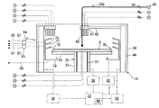
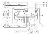
- the top view which shows the metal-plating processing apparatus by one embodiment of this invention The side view which shows the composite plating processing unit of the plating processing apparatus by one embodiment of this invention.
- a plating apparatus 1 is provided at the front end, and carries a plurality of substrates (here, 25 semiconductor wafers) (for example, 25 wafers) together and carried in and out by a carrier 3.
- the substrate 4 is provided at the rear of the substrate loading / unloading table 4, and is provided at the substrate loading / unloading chamber 5 for loading and unloading the substrates 2 accommodated in the carrier 3 by a predetermined number, and the substrate loading / unloading chamber 5 at the rear And a substrate processing chamber 6 for performing various processes such as a plating process and a cleaning process.
- the substrate loading / unloading table 4 is configured so that the four carriers 3 can be placed in close contact with the front wall 7 of the substrate loading / unloading chamber 5 and with a gap between the carriers 3.
- a transfer chamber 9 that houses the transfer device 8 is provided on the front side of the substrate carry-in / out chamber 5.
- a substrate transfer chamber 11 that houses the substrate transfer table 10 is provided on the rear side of the substrate carry-in / out chamber 5.
- the transfer chamber 9 and the substrate delivery chamber 11 are connected in communication via a delivery port 12.
- the substrate loading / unloading chamber 5 loads and unloads a predetermined number of substrates 2 between any one of the carriers 3 placed on the substrate loading / unloading table 4 and the substrate transfer table 10 using the transfer device 8. Is configured to do.
- a substrate transfer unit 13 extending in the front-rear direction is provided at the center of the substrate processing chamber 6.
- four composite plating units 14 to 17 capable of sequentially performing different types of plating processes are provided side by side.
- two composite plating processing units 18, 19 and two single plating processing units 20, 21 capable of performing one type of plating processing are provided side by side. ing.
- a substrate transfer device 22 that can move in the front-rear direction is accommodated in the substrate transfer unit 13.
- the substrate transfer unit 13 communicates with the substrate transfer table 10 in the substrate transfer chamber 11 via the substrate transfer port 23.
- the substrate transfer chamber 11 and the single plating processing units 20, 21 are provided between the substrate transfer chamber 11 and the composite plating processing units 14-19. Or between the composite plating processing units 14 to 19 and the single plating processing units 20 and 21, the substrates 2 are transported while being held horizontally one by one. In each of the plating units 14 to 21, the substrate 2 is washed and plated one by one.
- the six composite plating processing units 14 to 19 have the same configuration, and the two single plating processing units 20 and 21 also have the same configuration. Therefore, in the following description, the configuration of the composite plating processing unit 14 and the configuration of the single plating processing unit 20 will be described.
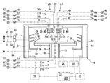
- the composite plating unit 14 includes a casing 24, substrate rotation holding means 25 for rotating the substrate 2 in a state where the substrate 2 is held horizontally inside the casing 24, and a cleaning treatment liquid on the substrate 2.
- Cleaning treatment liquid supply means 26 for supplying the substrate 2
- rinse treatment liquid supply means 27 for supplying the rinse treatment liquid to the substrate 2
- drying treatment means 28 for supplying the drying treatment agent to the substrate 2 and drying the substrate 2
- a plurality of Plating treatment means here, replacement plating treatment liquid supply means 29 for supplying a plating treatment liquid for subjecting the substrate 2 to substitution plating, and chemical reduction for supplying a plating treatment liquid for subjecting the substrate 2 to chemical reduction plating
- Plating solution supply means 30 treatment solution discharge means 31 (plating treatment solution discharge means) for discharging various treatment liquids (cleaning treatment liquid, rinse treatment liquid, drying treatment liquid, plating treatment liquid) supplied to the substrate 2; Have .
- a control means 32 is connected to the processing liquid discharge means 31.
- the control means 32 is also connected to the composite plating processing units 14 to 19, the single plating processing units 20, 21 and the substrate transfer unit 13, so as to drive and control the entire plating processing apparatus 1.
- the substrate rotation holding means 25 is rotatably attached to the casing 24 and extends in the casing 24 up and down in a hollow cylindrical rotation shaft 33, and a turntable 34 horizontally attached to the upper end portion of the rotation shaft 33.
- the wafer chuck 35 is attached to the outer peripheral portion of the upper surface of the turntable 34 at intervals in the circumferential direction.
- a rotation mechanism 36 is connected to the rotation shaft 33 of the substrate rotation holding means 25.
- the rotation mechanism 36 is connected to the control means 32 and is driven and controlled by the control means 32.
- the rotation shaft 33 of the substrate rotation holding means 25 is rotated by the rotation mechanism 36, and accordingly, the substrate 2 held horizontally by the wafer chuck 35 is rotated.
- the cleaning processing liquid supply means 26 includes first and second cleaning processing liquid supply means 26 a and 26 b that supply the cleaning processing liquid to the surface of the substrate 2, and a third cleaning that supplies the cleaning processing liquid to the back surface of the substrate 2. And a processing liquid supply means 26c.
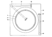
- the first cleaning treatment liquid supply means 26a is rotatably attached to one side of the casing 24 and extends vertically, and a rotation mechanism 38 such as a motor or an actuator connected to the support shaft 37, An arm 39 whose base end is attached horizontally to the upper end of the support shaft 37, a nozzle head 40 attached to the tip of the arm 39, and attached to the nozzle head 40 downward (upper surface of the substrate 2) Nozzle 41 is provided.
- the nozzle 41 has a cleaning treatment liquid supply source 42 for supplying a chemical solution made of an inorganic acid containing hydrofluoric acid or an organic acid containing malic acid or the like as a cleaning treatment liquid via a flow rate adjusting valve 43.
- the rotation mechanism 38 and the flow rate adjusting valve 43 are connected to the control means 32 and controlled by the control means 32.
- the second cleaning treatment liquid supply means 26b is rotatably attached to the other side of the casing 24 and extends vertically, and a rotation mechanism 45 such as a motor or an actuator connected to the support shaft 44, An arm 46 whose base end is attached horizontally to the upper end of the support shaft 44, a nozzle head 47 attached to the tip of the arm 46, and attached to the nozzle head 47 downward (upper surface of the substrate 2) Nozzle 48.
- the nozzle 48 is supplied with a cleaning processing liquid supply source 49 (a cleaning processing liquid supply source 42 and a cleaning processing liquid supply source 42) for supplying a chemical liquid made of an inorganic acid including hydrofluoric acid or an organic acid including malic acid as a cleaning processing liquid. May be the same), but is connected via a flow rate adjusting valve 50.
- the rotating mechanism 45 and the flow rate adjusting valve 50 are connected to the control means 32 and controlled by the control means 32.
- the third cleaning treatment liquid supply means 26c is fixed to the casing 24 and has a cylindrical shaft body 51 accommodated in the hollow portion of the rotation shaft 33 of the substrate rotation holding means 25 with a space from the rotation shaft 33. And a nozzle 52 formed on the shaft body 51.
- the nozzle 52 is supplied with a cleaning processing liquid supply source 53 (cleaning processing liquid supply source 42, cleaning liquid supplying a chemical liquid made of an inorganic acid containing hydrofluoric acid or an organic acid containing malic acid or the like as a cleaning processing liquid. 49 may be the same as 49.), but is connected via a flow rate adjusting valve 54.
- the flow rate adjusting valve 54 is connected to the control means 32 and is controlled by the control means 32.
- the cleaning liquid supply means 26 rotates the support shaft 37 (44) by the rotation mechanism 38 (45) so that the nozzle 41 (48) is retracted to the outside of the outer peripheral portion of the substrate 2.
- the cleaning processing liquid whose flow rate is adjusted by the flow rate adjusting valve 43 (50) from the nozzle 41 (48) to the upper side of the substrate 2 is moved from the nozzle 41 (48) to the supply position above the central portion of the substrate 2 Supply.
- the cleaning processing liquid supply means 26 (26c) supplies the cleaning processing liquid whose flow rate is adjusted by the flow rate adjusting valve 54 from the nozzle 52 toward the lower side of the substrate 2.
- the nozzle 41 (48) may be disposed above the center of the substrate 2 and the cleaning solution may be supplied toward the center above the substrate 2, and the nozzle 41 (48) may be provided on the substrate 2. You may make it supply a cleaning process liquid toward the upper surface of the board
- the rinse treatment liquid supply means 27 also includes first and second rinse treatment liquid supply means 27a and 27b for supplying the rinse treatment liquid to the surface of the substrate 2, and a third rinse for supplying the rinse treatment liquid to the back surface of the substrate 2. And a processing liquid supply means 27c.
- the first rinse treatment liquid supply means 27a shares the support shaft 37, the rotation mechanism 38, the arm 39, and the nozzle head 40 with the first cleaning treatment liquid supply means 26a, and the nozzle 55 attached to the nozzle head 40.
- a rinse treatment liquid supply source 56 that is connected to the nozzle 55 via a flow rate adjusting valve 57 and supplies pure water as a rinse treatment liquid.
- the flow rate adjusting valve 57 is connected to the control means 32 and is controlled by the control means 32.
- the second rinse treatment liquid supply means 27b shares the support shaft 44, the rotation mechanism 45, the arm 46 and the nozzle head 47 with the second cleaning treatment liquid supply means 26b, and a nozzle 58 attached to the nozzle head 47.
- a rinsing process liquid supply source 59 (which may be the same as the rinsing process liquid supply source 56) connected to the nozzle 58 via a flow rate adjusting valve 60 and supplying pure water as a rinsing process liquid.
- the flow rate adjusting valve 60 is connected to the control means 32 and is controlled by the control means 32.
- the third rinse treatment liquid supply means 27c shares the shaft body 51 with the third cleaning treatment liquid supply means 26c.
- the nozzle 61 formed on the shaft body 51 and the nozzle 61 via the flow rate adjustment valve 63 are shared.
- a rinse treatment liquid supply source 62 for supplying pure water as a rinse treatment liquid may be the same as the rinse treatment liquid supply sources 56 and 59).
- the flow rate adjusting valve 63 is connected to the control means 32 and is controlled by the control means 32.
- the rinsing treatment liquid supply means 27 rotates the support shaft 37 (44) by the rotation mechanism 38 (45), so that the nozzle 55 (58) is retracted to the outside of the outer peripheral portion of the substrate 2.
- the rinsing liquid whose flow rate is adjusted by the flow rate adjusting valve 57 (60) is moved from the nozzle 55 (58) to the upper side of the substrate 2 from the nozzle 55 (58) to the supply position above the center of the substrate 2 Supply.
- the rinsing process liquid supply means 27 (27c) supplies the rinsing process liquid whose flow rate is adjusted by the flow rate adjusting valve 63 from the nozzle 61 toward the lower side of the substrate 2.
- the nozzle 55 (58) may be disposed above the center of the substrate 2 and the rinsing liquid may be supplied toward the center above the substrate 2, and the nozzle 55 (58) may be provided on the substrate 2.
- the rinse treatment liquid may be supplied toward the upper surface of the substrate 2 while being moved between the center portion and the outer peripheral edge portion.
- the drying processing means 28 includes a first drying processing means 28a that performs a drying process on the surface of the substrate 2 and a second drying processing means 28b that performs a drying process on the back surface of the substrate 2.
- the first drying processing means 28a shares the support shaft 37, the rotation mechanism 38, the arm 39 and the nozzle head 40 with the first cleaning processing liquid supply means 26a and the first rinsing processing means 27a.
- a drying processing liquid supply source 65 that is connected to the nozzle 64 via a flow rate adjusting valve 66 and supplies IPA (isopropyl alcohol) as a drying processing liquid.
- the flow rate adjusting valve 66 is connected to the control means 32 and is controlled by the control means 32.
- the second drying processing means 28b shares the shaft body 51 with the third cleaning processing liquid supply means 26c and the third rinsing processing liquid supply means 27c, and includes a nozzle 67 formed on the shaft body 51, a nozzle A dry processing agent supply source 68 for supplying nitrogen as a dry processing agent is connected to 67 through a flow rate adjusting valve 69.
- the flow rate adjusting valve 69 is connected to the control means 32 and is controlled by the control means 32.
- the drying processing means 28 (28a) rotates the support shaft 37 by the rotation mechanism 38, whereby the nozzle 64 is moved from the retracted position outside the outer peripheral portion of the substrate 2 to the supply position above the center portion of the substrate 2. , And the dry processing liquid whose flow rate is adjusted by the flow rate adjusting valve 66 is supplied from the nozzle 64 toward the upper side of the substrate 2. Further, the drying processing means 28 (28b) supplies the drying processing agent whose flow rate is adjusted by the flow rate adjusting valve 69 from the nozzle 67 to the lower side of the substrate 2. In this case, the nozzle 64 may be disposed above the center portion of the substrate 2 to supply the drying processing liquid toward the upper center portion of the substrate 2. You may make it supply a drying process liquid toward the upper surface of the board
- the displacement plating treatment liquid supply means 29 includes a support shaft 37, a rotation mechanism 38, an arm 39, and a nozzle head 40, a first cleaning treatment liquid supply means 26a, a first rinse treatment means 27a, and a first drying treatment means 28a.
- a nozzle 70 attached to the nozzle head 40 is connected to the nozzle 70 via a flow rate adjusting valve 72, and a plating solution containing, for example, palladium is supplied as a plating solution for performing substitution plating.
- a displacement plating solution supply source 71 is connected to the control means 32 and is controlled by the control means 32.
- the replacement plating solution supply source 71 supplies the replacement plating solution at a predetermined temperature.
- the replacement plating solution supply means 29 rotates the support shaft 37 by the rotation mechanism 38, so that the nozzle 70 moves from the retracted position outside the outer peripheral portion of the substrate 2 to the supply position above the center portion of the substrate 2.
- the displacement plating process liquid whose flow rate is adjusted by the flow rate adjusting valve 72 is supplied from the nozzle 70 toward the upper side of the substrate 2.
- the nozzle 70 may be disposed above the center portion of the substrate 2 and the replacement plating solution may be supplied toward the upper center portion of the substrate 2.
- the displacement plating solution may be supplied toward the upper surface of the substrate 2 while moving between the upper edge portions.
- the chemical reduction plating treatment liquid supply means 30 shares the support shaft 44, the rotation mechanism 45, the arm 46 and the nozzle head 47 with the second cleaning treatment liquid supply means 26b and the second rinse treatment means 27b, and the nozzle head Nozzle 73 attached to 47 and a chemical reduction plating process connected to nozzle 73 via flow rate adjusting valve 75 and supplying a plating treatment liquid containing, for example, nickel or cobalt as a plating treatment liquid for performing chemical reduction plating A liquid supply source 74.
- the flow rate adjusting valve 75 is connected to the control means 32 and is controlled by the control means 32.
- the chemical reduction plating treatment liquid supply source 74 supplies the chemical reduction plating treatment liquid at a predetermined temperature.
- the chemical reduction plating solution supply means 30 rotates the support shaft 44 by the rotation mechanism 45 so that the nozzle 73 moves from the retracted position outside the outer peripheral portion of the substrate 2 to the supply position above the center portion of the substrate 2. 2, the chemical reduction plating solution whose flow rate is adjusted by the flow rate adjusting valve 75 is supplied from the nozzle 73 toward the upper side of the substrate 2.
- the nozzle 73 may be disposed above the center of the substrate 2 and the chemical reduction plating solution may be supplied toward the center above the substrate 2, and the nozzle 73 may be disposed above the center of the substrate 2. You may make it supply a chemical reduction plating process liquid toward the upper surface of the board
- the treatment liquid discharge means 31 is disposed outside the turntable 34, has a cup 79 having discharge ports 76, 77, 78 stacked in three upper and lower stages for discharging each processed liquid after treatment, and the uppermost and middle stages.
- Recovery passages 80, 81 and waste passages 82, 83 connected to the outlets 76, 77 via the passage changers 84, 85, and a waste passage 86 connected to the lowermost outlet 79, have.
- the flow path switches 84 and 85 are connected to the control means 32 and are controlled by the control means 32.
- the recovery channels 80 and 81 are channels for allowing the processing liquid to be reused after being recovered
- the discard channels 82, 83, and 86 are channels for discarding the processing liquid. is there.
- the processing liquid discharge means 31 has an elevating mechanism 87 connected to the cup 79.
- the elevating mechanism 87 is connected to the control means 32 and is driven and controlled by the control means 32.
- the elevating mechanism 87 elevates and lowers the cup 79 relative to the substrate 2.
- the elevating mechanism 87 may be provided in the substrate rotation holding means 25 to elevate the substrate 2.
- the processing liquid discharge means 31 moves the cup 79 up and down by the lifting mechanism 87 so that one of the discharge ports 76, 77, 78 is positioned directly outside the substrate 2, thereby causing the processing scattered from the substrate 2. Separate and drain the liquid.
- the processing liquid discharge means 31 reuses the processing liquid recovered at the discharge ports 76 and 77 by switching the flow path to the recovery flow paths 80 and 81 by the flow path switches 84 and 85. Then, the processing liquid collected at the discharge ports 76 and 77 and the discharge port 78 is discarded by switching the flow channel to the discard flow channels 82 and 83 side by the flow channel switches 84 and 85.
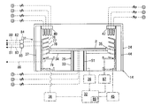
- the single plating processing unit 20 includes a substrate rotation holding means 25 and cleaning processing liquid supply means 26 (first and third cleaning processing liquid supply means 26a, 26c, as in the case of the composite plating processing unit 14. ), Rinse treatment liquid supply means 27 (first and third rinse treatment liquid supply means 27a, 27c), dry treatment means 28 (first and second dry treatment means 28a, 28b), and one plating treatment liquid. Supply means (substitution plating treatment liquid supply means 29) and treatment liquid discharge means 31 are provided.
- the substrate rotation holding means 25, the cleaning treatment liquid supply means 26, the rinse treatment liquid supply means 27, the drying treatment means 28, the plating treatment liquid supply means, and the treatment liquid discharge means 31 are accommodated in the casing 88.
- the substrate rotation holding means 25, the cleaning treatment liquid supply means 26, the rinse treatment liquid supply means 27, the drying treatment means 28, the displacement plating treatment liquid supply means 29, and the treatment liquid discharge means 31 are connected to the control means 32.
- the replacement plating treatment liquid supply means 29 is provided as the plating treatment liquid supply means, and the chemical reduction plating treatment liquid supply means 30 is not provided.
- a plating processing solution containing gold is used as a plating processing solution for performing replacement plating supplied by the replacement plating processing solution supply means 29.
- the plating apparatus 1 includes the composite plating processing units 14 to 19, the single plating processing units 20 and 21, and the composite plating processing units 14 to 19 and the single plating processing units 20 and 21. And a substrate transfer unit 13 for carrying.
- Each of the composite plating processing units 14 to 19 includes a substrate rotation holding means 25, a plurality of plating treatment liquid supply means (here, a replacement plating treatment liquid supply means 29 and a chemical reduction plating treatment liquid supply means 30), and a plating treatment liquid. It has a discharge means (treatment liquid discharge means 31), and these means are accommodated in the casing 24 so that the surface of the substrate 2 is sequentially subjected to a plurality of plating processes.
- the single plating processing units 20 and 21 each have a substrate rotation holding means 25, a single plating processing liquid supply means (here, a replacement plating processing liquid supply means 29), and a plating processing liquid discharge means (processing liquid discharge means 31). These means are accommodated in the casing 88, and the surface of the substrate 2 is plated once.
- the plating apparatus 1 can appropriately use the composite plating processing units 14 to 19 and / or the single plating processing units 20 and 21 according to the type of plating processing to be performed on the substrate 2.
- the number of composite plating units 14 to 19 (here, four) is larger than the number of single plating units 20, 21 (here, two). . Therefore, the composite plating processing units 14 to 19 having a long processing time and the single plating processing units 20 and 21 having a short processing time can be efficiently operated, and the throughput of the plating processing apparatus 1 can be improved.
- the above-described plating processing apparatus 1 gold plating is separated from the composite plating processing units 14 to 19 and performed by the single plating processing units 20 and 21. Therefore, the maintainability of the composite plating units 14 to 19 is improved and, for example, after the palladium plating and nickel (or cobalt) plating or palladium plating is performed in the composite plating units 14 to 19, the single plating units 20 and 21 are performed.
- the surface of palladium or nickel (or cobalt) can be gold-plated, and can be used properly according to the plating treatment.
- the plating apparatus 1 performs plating with an acidic plating solution containing nickel, palladium, etc., in the composite plating units 14 to 19, and performs single plating with an alkaline plating solution containing gold.
- the plating units 20 and 21 it is possible to prevent processes having different atmospheres from being mixed.
- the plating apparatus 1 is configured as described above, and is driven and controlled by the control means 32 according to various programs recorded on the recording medium 89 provided in the control means 32 so as to process the substrate 2.
- the recording medium 89 stores various setting data and various programs such as a plating process program to be described later, a computer-readable memory such as ROM and RAM, a hard disk, a CD-ROM, a DVD-
- a computer-readable memory such as ROM and RAM
- a hard disk such as a CD-ROM, a DVD-
- a known device such as a disk-shaped storage medium such as a ROM or a flexible disk can be used.
- the plating process is performed on the substrate 2 as described below according to the plating process program recorded in the recording medium 89 provided in the control means 32 (see FIG. 5).
- palladium plating is applied to the substrate 2 by displacement plating in the composite plating processing unit 14
- nickel plating is then applied by chemical reduction plating
- gold plating is then applied to the substrate 2 in the single plating processing unit 20. The case where it applies by will be described.
- the plating processing program executes the substrate carry-in step S1.
- one substrate 2 is carried into the composite plating processing unit 14 from the substrate delivery chamber 11 using the substrate carrying device 22 of the substrate carrying unit 13.
- the plating processing program executes the substrate receiving step S2 in the composite plating processing unit 14.
- the cup 79 is lowered to a predetermined position by the lifting mechanism 87, and one substrate 2 carried into the casing 24 from the substrate transfer device 22 is moved by the wafer chuck 35. Then, the cup 79 is moved up to a position where the lowermost discharge port 78 and the outer peripheral edge of the substrate 2 face each other. At this time, the plating processing program rotates the support shafts 37 and 44 by the rotation mechanisms 38 and 45 to retract the nozzle heads 40 and 47 to the retreat position outside the outer periphery of the turntable 34.
- the plating processing program executes the pre-substrate cleaning step S3 in the composite plating processing unit 14.
- the rotating shaft 33 is rotated by the rotating mechanism 36 of the substrate rotation holding means 25 to rotate the substrate 2 together with the turntable 34, and the first rinsing treatment liquid
- the support shaft 37 is rotated by the rotation mechanism 38 of the supply means 27a to move the nozzle 55 to the supply position above the center portion of the substrate 2.
- the rinsing process liquid adjusted to a predetermined flow rate by the flow rate adjusting valve 57 of the first rinsing process liquid supply means 27 a is supplied from the nozzle 55 toward the upper surface of the substrate 2.
- substrate 2 is performed.
- the rinse treatment liquid after the treatment is collected at the lowermost discharge port 78 of the cup 79 of the treatment liquid discharge means 31, and is discarded from the disposal flow path 86. Thereafter, the supply of the rinse treatment liquid by the first rinse treatment liquid supply means 27a is stopped.
- the support shaft 37 is rotated by the rotating mechanism 38 of the first cleaning processing liquid supply means 26a to bring the nozzle 41 to the supply position above the center of the substrate 2.
- the cleaning processing liquid adjusted to a predetermined flow rate by the flow rate adjusting valve 43 of the first cleaning processing liquid supply means 26 a is supplied from the nozzle 41 toward the upper surface of the substrate 2.
- the treated cleaning treatment liquid is collected at the lowermost discharge port 78 of the cup 79 of the treatment liquid discharge means 31 and discarded from the disposal flow path 86.
- the supply of the cleaning processing liquid by the first cleaning processing liquid supply means 26a is stopped.
- the top surface of the substrate 2 is rinsed in the same manner as the rinse before the cleaning (see FIG. 7).
- the plating processing program executes the replacement plating processing step S4 in a state where the substrate 2 immediately after the rinsing processing in the substrate pre-cleaning step S3 is not dried.
- the displacement plating process step S4 in a state where the substrate 2 is not dried, it is possible to prevent copper or the like on the surface to be plated of the substrate 2 from being oxidized and failing to perform the displacement plating process satisfactorily. Can do.
- the cup 79 is moved to the middle outlet by the lifting mechanism 87 of the processing liquid discharge means 31 while the substrate 2 is rotated by the rotation mechanism 36 of the substrate rotation holding means 25. 77 and the outer peripheral edge of the substrate 2 are lowered to a position where they face each other, and the support shaft 37 is rotated by the rotation mechanism 38 of the replacement plating solution supply means 29 to move the nozzle 70 to the supply position above the center of the substrate 2.
- a normal temperature substitution plating treatment liquid containing palladium adjusted to a predetermined flow rate by the flow rate adjustment valve 72 of the substitution plating treatment liquid supply means 29 is supplied from the nozzle 70 toward the upper surface of the substrate 2.
- the replacement plating solution is collected at the middle outlet 77 of the cup 79 of the treatment solution discharge means 31.
- the rinse treatment solution, the cleaning treatment solution, and the replacement plating treatment solution are changed. If they are mixed, discard them from the waste flow path 83, and if the rinse treatment liquid and cleaning liquid are not mixed, collect them from the recovery flow path 81 and reuse the recovered displacement plating treatment liquid. ing. Thereafter, the supply of the replacement plating solution by the replacement plating solution supply means 29 is stopped.
- the flow path switching of the flow path switching device 85 may be switched over time, or the flow path may be switched by detecting the presence or absence of the rinse treatment liquid by a sensor.
- the movement speed of the nozzle 70 of the displacement plating solution supply means 29 is made slower on the outer peripheral portion of the substrate 2 than the inner peripheral portion of the substrate 2, or the discharge amount of the plating treatment liquid is increased.
- the temperature of the substrate 2 can be controlled to be uniform by increasing the temperature of the discharged plating treatment liquid.
- the top surface of the substrate 2 is rinsed in the same manner as the rinse treatment in the substrate pre-cleaning step S3 (see FIG. 7).
- the plating processing program executes the substrate intermediate cleaning step S5 in the composite plating processing unit 14.
- the substrate intermediate cleaning step S5 may be omitted.
- the first rinse treatment liquid supply means 27a rinses the upper surface of the substrate, and the third rinse treatment liquid supply means 26a cleans the lower surface of the substrate, and then the third rinse.
- the lower surface of the substrate is rinsed by the processing liquid supply means 27c.
- the support shaft 37 is rotated by the rotation mechanism 38 so that the nozzle head 40 is retracted to the retracted position outside the outer periphery of the turntable 34.
- the plating processing program 14 performs the chemical reduction plating processing step S6 following the rinsing processing in the substrate intermediate cleaning step S5 (or the replacement plating processing step S4 when the substrate intermediate cleaning step S5 is omitted). Execute.
- the displacement plating treatment step S4 and the chemical reduction plating treatment step S6 can be performed inside one unit. Therefore, the displacement plating treatment step S4 and the chemical reduction plating treatment step S6 are performed. There is no need to transport the substrate 2 between the two, and the drying process of the substrate 2 can be omitted, so that the throughput can be improved. Further, the surface of the substrate 2 can be prevented from being oxidized, and the surface of the substrate 2 can be satisfactorily plated.
- the substrate 2 is driven at a low speed by rotating the turntable 34 at a lower speed than the rotation speed in the replacement plating process S4 by the rotation mechanism 36 of the substrate rotation holding means 25. Rotate. Further, the elevating mechanism 87 of the processing liquid discharge means 31 lowers the cup 79 to a position where the uppermost discharge port 76 and the outer peripheral edge of the substrate 2 face each other. Further, the support shaft 44 is rotated by the rotation mechanism 45 of the chemical reduction plating solution supply means 30 to move the nozzle 73 to the supply position above the center of the substrate 2. Thereafter, a high-temperature (80 ° C.
- chemical reduction plating solution containing nickel adjusted to a predetermined flow rate by the flow rate adjustment valve 75 of the chemical reduction plating solution supply means 30 is supplied from the nozzle 73 to the upper surface of the substrate 2. Supply towards Thereby, nickel plating is performed on the upper surface of the substrate 2 by chemical reduction plating.
- the treated chemical reduction plating solution is recovered at the uppermost discharge port 76 of the cup 79 of the treatment solution discharge means 31, and by switching the flow path switch 84, the rinse treatment solution and the cleaning treatment solution are combined with the chemical reduction plating. If the treatment liquid is mixed, discard it from the waste flow path 82, and if the rinse treatment liquid or cleaning treatment liquid is not mixed, collect it from the collection flow path 80 and remove the collected chemical reduction plating treatment liquid.
- the channel switching of the channel switching unit 84 may be performed over time, or the channel may be switched by detecting the presence or absence of the rinsing liquid using a sensor.
- the substrate 2 is rotated at a lower speed than the rotation speed of the substrate 2 in the displacement plating process S4.
- the substrate is rotated by the substrate rotation holding means 25 according to the type (temperature) of the plating treatment liquid supplied from the plurality of plating treatment liquid supply means (the replacement plating treatment liquid supply means 29 and the chemical reduction plating treatment liquid supply means 30).
- the rotation speed of 2 it is possible to suppress the substrate 2 and the plating solution from being cooled by heat dissipation by rotating the substrate 2, and particularly when using a high-temperature plating solution.
- By lowering the rotation speed of the substrate 2 it is possible to satisfactorily perform plating with a predetermined thickness on the substrate 2 while suppressing the temperature drop of the plating solution.
- the chemical reduction plating treatment liquid is discharged from the discharge port 76 different from the discharge port 77 of the cup 79 in the replacement plating treatment step S4, depending on the type of the plating treatment solution.
- the plating solution is discharged from the different discharge ports 76 and 77 to prevent mixing of the plating solution.
- the moving speed of the nozzle 73 of the chemical reduction plating treatment liquid supply means 30 is made slower at the outer peripheral portion of the substrate 2 than the inner peripheral portion of the substrate 2, and the discharge amount of the plating treatment liquid is reduced.
- the temperature of the substrate 2 can be controlled to be uniform by increasing the temperature or increasing the temperature of the discharged plating treatment liquid.
- the cup 79 is raised to a position where the lowermost discharge port 78 and the outer peripheral edge of the substrate 2 face each other by the lifting mechanism 87 of the treatment liquid discharge means 31.
- the support shaft 44 is rotated by the rotation mechanism 45 of the second rinse treatment liquid supply means 27b to move the nozzle 58 to the supply position above the center of the substrate 2.
- the rinse treatment liquid adjusted to a predetermined flow rate by the flow rate adjustment valve 60 of the second rinse treatment liquid supply means 27 b is supplied from the nozzle 58 toward the upper surface of the substrate 2. Thereby, the rinse process of the upper surface of the board
- substrate 2 is performed.
- the rinse treatment liquid after the treatment is collected at the lowermost discharge port 78 of the cup 79 of the treatment liquid discharge means 31, and is discarded from the disposal flow path 86. Thereafter, the supply of the rinse treatment liquid by the second rinse treatment liquid supply means 27b is stopped.
- the plating processing program executes the post-substrate cleaning step S7 in the composite plating processing unit 14.
- the support shaft 44 is rotated by the rotation mechanism 45 of the second cleaning processing liquid supply means 26b to move the nozzle 48 to the supply position above the center of the substrate 2.
- the cleaning processing liquid adjusted to a predetermined flow rate by the flow rate adjusting valve 50 of the second cleaning processing liquid supply means 26 b is supplied from the nozzle 48 toward the upper surface of the substrate 2.
- the treated cleaning treatment liquid is collected at the lowermost discharge port 78 of the cup 79 of the treatment liquid discharge means 31 and discarded from the disposal flow path 86.
- the supply of the cleaning treatment liquid by the second cleaning treatment liquid supply means 26b is stopped.
- the first rinsing process liquid supply means 27a rinses the upper surface of the substrate, and the third cleaning process liquid supply means 26c cleans the lower surface of the substrate.
- the bottom surface of the substrate is rinsed by the rinse treatment liquid supply means 27c.
- the support shaft 44 is rotated by the rotation mechanism 45 to move the nozzle head 47 to the retracted position outside the outer periphery of the substrate 2.
- the plating processing program executes the substrate drying step S8 in the composite plating processing unit 14.
- the support shaft 37 is rotated by the rotation mechanism 38 of the first drying processing means 28a to move the nozzle 64 to the supply position above the center of the substrate 2.
- the drying processing liquid adjusted to a predetermined flow rate by the flow rate adjusting valve 66 of the drying processing means 28 is supplied from the nozzle 64 toward the upper surface of the substrate 2, and the flow rate adjusting valve 69 of the second drying processing means 28b.
- the drying treatment agent adjusted to a predetermined flow rate is supplied from the nozzle 67 toward the lower surface of the substrate 2. Thereby, the drying process of the upper and lower surfaces of the substrate 2 is performed.
- the processed dry processing liquid is collected at the lowermost discharge port 78 of the cup 79 of the processing liquid discharging means 31, and is discarded from the disposal flow path 86. Thereafter, the drying processing by the first and second drying processing means 28a, 28b is stopped, and the support shaft 37 is rotated by the rotation mechanism 38 to move the nozzle head 40 to the retracted position outside the outer periphery of the substrate 2.
- the plating processing program executes the substrate delivery process S9.
- the cup 79 is lowered to a predetermined position by the elevating mechanism 87, and the substrate 2 held horizontally by the substrate rotation holding means 25 is delivered to the substrate transport device 22.
- the plating processing program executes the substrate transfer step S10.
- a single substrate 2 is transferred from the composite plating processing unit 14 to the single plating processing unit 20 using the substrate transfer device 22 of the substrate transfer unit 13.
- the plating process program is similar to the processes S2 to S4 and S7 to S9 in the composite plating process unit 14, with the substrate receiving process S11, the substrate pre-cleaning process S12, and the displacement plating process S13. Then, the post-substrate cleaning step S14, the substrate drying step S15, and the substrate delivery step S16 are sequentially executed.
- gold is plated on the substrate 2 by displacement plating using a plating treatment liquid containing gold as the displacement plating treatment step S 13.
- the substrate 2 is rotated at a lower speed than the rotation speed in the replacement plating process S4 in the composite plating unit 14, and the replacement plating process is performed.
- a high temperature (80 ° C. to 85 ° C.) substitution plating treatment liquid containing gold is supplied from the liquid supply source 71.
- the replacement plating treatment liquid mixed with the rinse treatment liquid is also collected.
- the plating processing program executes the substrate unloading step S17.
- one substrate 2 is unloaded from the single plating processing unit 20 to the substrate delivery chamber 11 using the substrate transfer device 22 of the substrate transfer unit 13.
- the plating apparatus 1 a plurality of platings for supplying different types of plating treatment liquids (here, a palladium-containing substitution plating treatment liquid and a nickel-containing chemical reduction plating treatment liquid) to the surface of the substrate 2. Since the treatment liquid supply means (here, the displacement plating treatment liquid supply means 29 and the chemical reduction plating treatment liquid supply means 30) are provided, the size of the plating apparatus 1 can be reduced. Also, different plating treatment liquids are sequentially supplied to the surface of the substrate 2 while the substrate 2 is held in rotation, and a plurality of plating treatments are sequentially performed on the surface of the substrate 2.
- plating treatment liquids here, a palladium-containing substitution plating treatment liquid and a nickel-containing chemical reduction plating treatment liquid
- the time required for transporting and drying the substrate 2 can be omitted, the processing time required for the plating process can be shortened, and the throughput of the plating apparatus 1 can be improved. Furthermore, by sequentially performing a plurality of plating processes on the surface of the substrate 2, it is possible to prevent the surface of the substrate 2 from being oxidized and to satisfactorily perform the plating process on the surface of the substrate 2.
- the substrate 2 when the plating process is performed with the high-temperature plating process liquid, the substrate 2 is rotated at a low speed to prevent the temperature of the plating process liquid from decreasing.
- the temperature drop of the plating solution can be prevented by the substrate temperature raising means that raises the temperature.
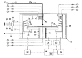
- the substrate temperature raising means 90 includes a donut bag-like flexible expandable / shrinkable heating body 91 disposed on the turntable 34, and a heated fluid (heating fluid: It may be liquid or gas.) And a circulation channel 93 connected to the tank 92.
- a heating body 91 is connected to the forward path side of the circulation flow path 93 via an opening / closing valve 94, and a heating body 91 is connected to the return path side of the circulation flow path 93 via a suction pump 95, so that the tank 92 A heater 96 is built in.
- the on-off valve 94, the suction pump 95, and the heater 96 are connected to the control means 32 and controlled by the control means 32.
- the nozzles 52, 61, and 67 are positioned in the central portion of the heating body 91 so that the discharge of the processing liquid from the nozzles 52, 61, and 67 is not hindered.
- the substrate temperature raising means 90 heats the heating fluid stored in the tank 92 by the heater 96 to a predetermined heating temperature, opens the opening / closing valve 94 and drives the suction pump 95 to heat the heating fluid.
- Supply to body 91 The heating body 91 is expanded by the supply pressure and brought into contact (contact) with the lower surface (back surface) of the substrate 2, and the substrate 2 is heated from the lower surface of the substrate 2 to raise the temperature.
- the substrate temperature raising means 90 closes the opening / closing valve 94 and drives the suction pump 95 for a predetermined time to suck the heating fluid from the heating body 91 and contract the heating body 91 by the suction pressure, Between the lower surface of the substrate 2 and the turntable 34, a gap through which the processing liquid discharged from the nozzles 52, 61, 67 flows is secured.
- the heating fluid is supplied into the bag-shaped heating body 91 so that the heating fluid and various processing liquids are not mixed.
- the substrate temperature raising means 90 can also change the heating temperature of the heating fluid according to the type (temperature) of the plating treatment solution.
- the substrate temperature raising means 90 divides the lower surface of the substrate 2 into a plurality of regions, and disposes a different heating element for each region, thereby changing the lower surface of the substrate 2 for each region (for example, the inner circumference of the substrate 2
- the temperature of the substrate 2 is increased to the region on the part side and the region on the outer peripheral part side, the temperature drop of the plating treatment liquid supplied to the substrate 2 is more reliably suppressed, the plating temperature is made uniform, and the plating thickness is increased. It can also be made uniform.
Landscapes
- Chemical & Material Sciences (AREA)
- Engineering & Computer Science (AREA)
- Organic Chemistry (AREA)
- Metallurgy (AREA)
- Chemical Kinetics & Catalysis (AREA)
- Materials Engineering (AREA)
- Mechanical Engineering (AREA)
- General Chemical & Material Sciences (AREA)
- Electrochemistry (AREA)
- Life Sciences & Earth Sciences (AREA)
- Sustainable Development (AREA)
- Wood Science & Technology (AREA)
- Chemically Coating (AREA)
- Cleaning Or Drying Semiconductors (AREA)
- Electrodes Of Semiconductors (AREA)
Abstract
Description
Claims (20)
- 基板の表面にめっき処理液を供給してめっき処理を行うめっき処理装置において、
前記基板を回転保持する基板回転保持手段と、
前記基板回転保持手段によって保持された前記基板の前記表面に、それぞれ互いに異なる種類の前記めっき処理液を供給する複数のめっき処理液供給手段と、
前記基板回転保持手段の周囲に設けられ、前記基板から飛散した前記めっき処理液をその種類ごとに分離して排出するめっき処理液排出手段と、
前記基板回転保持手段、前記複数のめっき処理液供給手段及び前記めっき処理液排出手段に接続され、前記基板回転保持手段、前記複数のめっき処理液供給手段及び前記めっき処理液排出手段を制御する制御手段とを備えた、めっき処理装置。 - 前記制御手段は、前記基板回転保持手段によって前記基板を回転保持した状態のまま、前記複数のめっき処理液供給手段を順に駆動して、前記基板の前記表面に対して順次複数のめっき処理を施す、請求項1に記載のめっき処理装置。
- 前記めっき処理液排出手段は、互いに上下に積層させて多段に設けられた複数の排出口と、前記排出口に接続され、前記排出口を前記基板回転保持手段に対して相対的に昇降させる昇降手段とを有する、請求項1に記載のめっき処理装置。
- 前記制御手段は、前記昇降手段を駆動することにより、前記複数のめっき処理液供給手段から供給される前記めっき処理液を、その種類に応じて異なる前記排出口から排出する、請求項3に記載のめっき処理装置。
- 前記基板の前記表面に洗浄処理液を供給する洗浄処理液供給手段と、前記基板の前記表面にリンス処理液を供給するリンス処理液供給手段と、前記基板から飛散した前記洗浄処理液と前記リンス処理液とを排出する処理液排出手段とをさらに備えた、請求項1に記載のめっき処理装置。
- 前記めっき処理液排出手段の各前記排出口に、再利用される前記めっき処理液を流すめっき処理液回収流路と、廃棄される前記めっき処理液を流すめっき処理液廃棄流路とがそれぞれ接続されている、請求項3に記載のめっき処理装置。
- 前記制御手段は、前記排出口から排出される前記めっき処理液に前記洗浄処理液又は前記リンス処理液が混入している場合、前記めっき処理液を前記めっき処理液廃棄流路から廃棄するように前記めっき処理液排出手段を制御する、請求項6に記載のめっき処理装置。
- 前記複数のめっき処理液供給手段は、置換めっきを行うためのめっき処理液を供給する置換めっき処理液供給手段と、化学還元めっきを行うためのめっき処理液を供給する化学還元めっき処理液供給手段とを有し、
前記制御手段は、前記置換めっき処理液供給手段を駆動した後に前記化学還元めっき処理液供給手段を駆動する、請求項1に記載のめっき処理装置。 - 基板の表面にめっき処理液を供給してめっき処理を行うめっき処理装置において、
前記基板の前記表面に順次複数種類のめっき処理を施す複合めっき処理ユニットと、
前記基板の前記表面に1種類のめっき処理を施す単発めっき処理ユニットと、
前記複合めっき処理ユニットと前記単発めっき処理ユニットとの間で前記基板の搬送を行う基板搬送ユニットと、
前記複合めっき処理ユニット、前記単発めっき処理ユニット及び前記基板搬送ユニットに接続され、前記複合めっき処理ユニット、前記単発めっき処理ユニット及び前記基板搬送ユニットを制御する制御手段とを備え、
前記複合めっき処理ユニットは、
前記基板を回転保持する基板回転保持手段と、
前記基板回転保持手段によって保持された前記基板の前記表面に、それぞれ互いに異なる種類の前記めっき処理液を供給する複数のめっき処理液供給手段と、
前記基板回転保持手段の周囲に設けられ、前記基板から飛散した前記めっき処理液をその種類ごとに分離して排出するめっき処理液排出手段とを有する、めっき処理装置。 - 前記制御手段は、前記複合めっき処理ユニットにより前記基板の前記表面に順次複数種類のめっき処理を施した後に、前記基板搬送ユニットにより前記基板を前記複合めっき処理ユニットから前記単発めっき処理ユニットへ搬送し、前記単発めっき処理ユニットにより前記基板の前記表面に1種類のめっき処理を施すように、前記複合めっき処理ユニット、前記単発めっき処理ユニット及び前記基板搬送ユニットを制御する、請求項9に記載のめっき処理装置。
- 前記複合めっき処理ユニットの個数を前記単発めっき処理ユニットの個数よりも多くした、請求項9に記載のめっき処理装置。
- 前記制御手段は、前記めっき処理液供給手段から供給される前記めっき処理液の種類に応じて、前記基板回転保持手段の回転速度を変更する、請求項1に記載のめっき処理装置。
- 前記制御手段は、前記基板の前記表面に供給される前記めっき処理液の量が前記基板の中心部よりも周縁部の方が多くなるように、前記めっき処理液供給手段を制御する、請求項1に記載のめっき処理装置。
- 前記制御手段は、前記基板の前記表面に供給する前記めっき処理液の温度が前記基板の中心部よりも周縁部の方が高くなるように、前記めっき処理液供給手段を制御する、請求項1に記載のめっき処理装置。
- 前記基板の温度を上昇させる基板温度上昇手段を更に備え、前記基板温度上昇手段は、高温流体によって膨張させた袋状部材を前記基板の前記裏面に接触させることにより、前記基板の前記温度を上昇させるように構成されている、請求項1に記載のめっき処理装置。
- 前記制御手段は、前記めっき処理液供給手段から供給される前記めっき処理液の種類に応じて、前記基板温度上昇手段の加熱温度を変更する、請求項15に記載のめっき処理装置。
- めっき処理装置を用いて、基板の表面にめっき処理液を供給してめっき処理を行うめっき処理方法において、
前記めっき処理装置は、前記基板を回転保持する基板回転保持手段と、前記基板回転保持手段によって保持された前記基板の前記表面に、それぞれ互いに異なる種類の前記めっき処理液を供給する複数のめっき処理液供給手段と、前記基板回転保持手段の周囲に設けられ、前記基板から飛散した前記めっき処理液をその種類ごとに分離して排出するめっき処理液排出手段とを有し、
前記めっき処理方法は、
前記複数のめっき処理液供給手段のうち一のめっき処理液供給手段から、前記基板の前記表面にめっき処理液を供給して、前記基板の前記表面にめっき処理を施す工程と、
前記複数のめっき処理液供給手段のうち他のめっき処理液供給手段から、前記基板の前記表面に前記一のめっき処理液供給手段から供給される前記めっき処理液と異なる種類のめっき処理液を供給して、前記基板の前記表面にめっき処理を施す工程とを有する、めっき処理方法。 - 前記めっき処理液排出手段は複数の排出口を有し、前記一のめっき処理液供給手段から供給される前記めっき処理液と、前記他のめっき処理液供給手段から供給される前記めっき処理液とは、前記めっき処理液排出手段の異なる前記排出口から排出される、請求項17に記載のめっき処理方法。
- めっき処理装置を用いて、基板の表面にめっき処理液を供給してめっき処理を行うめっき処理方法において、
前記めっき処理装置は、前記基板の前記表面に順次複数種類のめっき処理を施す複合めっき処理ユニットと、前記基板の前記表面に1種類のめっき処理を施す単発めっき処理ユニットと、前記複合めっき処理ユニットと前記単発めっき処理ユニットとの間で前記基板の搬送を行う基板搬送ユニットとを有し、
前記めっき処理方法は、
前記複合めっき処理ユニットを用いて、前記基板の前記表面に互いに異なる種類のめっき処理液を順次供給して、前記基板の前記表面に順次複数のめっき処理を施す工程と、
前記基板搬送ユニットを用いて、前記基板を前記複合めっき処理ユニットから前記単発めっき処理ユニットに搬送する工程と、
前記単発めっき処理ユニットを用いて、前記基板の前記表面に1種類のめっき処理液を供給して前記基板の前記表面にめっき処理を施す工程とを備えた、めっき処理方法。 - めっき処理装置を用いて基板の表面をめっき処理するめっき処理プログラムを記録した記録媒体において、
前記めっき処理プログラムは、めっき処理方法を実施するためのものであり、
前記めっき処理装置は、前記基板を回転保持する基板回転保持手段と、前記基板回転保持手段によって保持された前記基板の前記表面に、それぞれ互いに異なる種類の前記めっき処理液を供給する複数のめっき処理液供給手段と、前記基板回転保持手段の周囲に設けられ、前記基板から飛散した前記めっき処理液をその種類ごとに分離して排出するめっき処理液排出手段とを有し、
前記めっき処理方法は、
前記複数のめっき処理液供給手段のうち一のめっき処理液供給手段から、前記基板の前記表面にめっき処理液を供給して、前記基板の前記表面にめっき処理を施す工程と、
前記複数のめっき処理液供給手段のうち他のめっき処理液供給手段から、前記基板の前記表面に前記一のめっき処理液供給手段から供給される前記めっき処理液と異なる種類のめっき処理液を供給して、前記基板の前記表面にめっき処理を施す工程とを有する、記録媒体。
Priority Applications (2)
| Application Number | Priority Date | Filing Date | Title |
|---|---|---|---|
| US13/881,431 US9731322B2 (en) | 2010-10-27 | 2011-08-24 | Plating apparatus, plating method and storage medium having plating program stored thereon |
| KR1020137010818A KR101639628B1 (ko) | 2010-10-27 | 2011-08-24 | 도금 처리 장치 및 도금 처리 방법 그리고 도금 처리 프로그램을 기록한 기록 매체 |
Applications Claiming Priority (2)
| Application Number | Priority Date | Filing Date | Title |
|---|---|---|---|
| JP2010240543A JP5379773B2 (ja) | 2010-10-27 | 2010-10-27 | めっき処理装置及びめっき処理方法並びにめっき処理プログラムを記録した記録媒体 |
| JP2010-240543 | 2010-10-27 |
Publications (1)
| Publication Number | Publication Date |
|---|---|
| WO2012056801A1 true WO2012056801A1 (ja) | 2012-05-03 |
Family
ID=45993531
Family Applications (1)
| Application Number | Title | Priority Date | Filing Date |
|---|---|---|---|
| PCT/JP2011/069010 Ceased WO2012056801A1 (ja) | 2010-10-27 | 2011-08-24 | めっき処理装置及びめっき処理方法並びにめっき処理プログラムを記録した記録媒体 |
Country Status (5)
| Country | Link |
|---|---|
| US (1) | US9731322B2 (ja) |
| JP (1) | JP5379773B2 (ja) |
| KR (1) | KR101639628B1 (ja) |
| TW (1) | TWI479054B (ja) |
| WO (1) | WO2012056801A1 (ja) |
Families Citing this family (4)
| Publication number | Priority date | Publication date | Assignee | Title |
|---|---|---|---|---|
| KR101637248B1 (ko) * | 2015-12-10 | 2016-07-07 | (주)엔에스케이 엔지니어링 | 용융아연도금공정의 아연 분말 제거설비 |
| CN109082699B (zh) * | 2018-08-23 | 2019-12-17 | 中国人民解放军海军航空大学青岛校区 | 一种电子元件用可旋转全方位电镀装置 |
| US11352711B2 (en) * | 2019-07-16 | 2022-06-07 | Applied Materials, Inc. | Fluid recovery in semiconductor processing |
| JP7345403B2 (ja) * | 2020-01-22 | 2023-09-15 | 東京エレクトロン株式会社 | 基板処理装置及びパージ方法 |
Citations (6)
| Publication number | Priority date | Publication date | Assignee | Title |
|---|---|---|---|---|
| JPH07122523A (ja) * | 1993-10-28 | 1995-05-12 | Toshiba Corp | 半導体製造装置 |
| JP2000064087A (ja) * | 1998-08-17 | 2000-02-29 | Dainippon Screen Mfg Co Ltd | 基板メッキ方法及び基板メッキ装置 |
| JP2002129344A (ja) * | 2000-10-26 | 2002-05-09 | Ebara Corp | 無電解めっき装置 |
| JP2004149824A (ja) * | 2002-10-29 | 2004-05-27 | Murata Mfg Co Ltd | 金めっき液と該金めっき液を使用しためっき方法、及び電子部品の製造方法、並びに電子部品 |
| JP2004200273A (ja) * | 2002-12-17 | 2004-07-15 | Sony Corp | 半導体装置の製造方法 |
| JP2004339579A (ja) * | 2003-05-16 | 2004-12-02 | Ebara Corp | 電解処理装置及び方法 |
Family Cites Families (7)
| Publication number | Priority date | Publication date | Assignee | Title |
|---|---|---|---|---|
| US6660139B1 (en) | 1999-11-08 | 2003-12-09 | Ebara Corporation | Plating apparatus and method |
| JP2002026491A (ja) * | 2000-07-06 | 2002-01-25 | Seiko Epson Corp | プリント基板のメッキ方法、実装構造体、液晶装置および液晶装置の製造方法 |
| US6858084B2 (en) * | 2000-10-26 | 2005-02-22 | Ebara Corporation | Plating apparatus and method |
| JP3939124B2 (ja) * | 2001-10-15 | 2007-07-04 | 株式会社荏原製作所 | 配線形成方法 |
| JP4308577B2 (ja) * | 2003-04-14 | 2009-08-05 | 東京エレクトロン株式会社 | 基板処理方法及び基板処理装置 |
| JP4245996B2 (ja) | 2003-07-07 | 2009-04-02 | 株式会社荏原製作所 | 無電解めっきによるキャップ膜の形成方法およびこれに用いる装置 |
| JP4940008B2 (ja) * | 2007-04-25 | 2012-05-30 | 株式会社東芝 | めっき成膜装置および成膜制御方法 |
-
2010
- 2010-10-27 JP JP2010240543A patent/JP5379773B2/ja active Active
-
2011
- 2011-08-24 KR KR1020137010818A patent/KR101639628B1/ko active Active
- 2011-08-24 US US13/881,431 patent/US9731322B2/en active Active
- 2011-08-24 WO PCT/JP2011/069010 patent/WO2012056801A1/ja not_active Ceased
- 2011-10-26 TW TW100138892A patent/TWI479054B/zh active
Patent Citations (6)
| Publication number | Priority date | Publication date | Assignee | Title |
|---|---|---|---|---|
| JPH07122523A (ja) * | 1993-10-28 | 1995-05-12 | Toshiba Corp | 半導体製造装置 |
| JP2000064087A (ja) * | 1998-08-17 | 2000-02-29 | Dainippon Screen Mfg Co Ltd | 基板メッキ方法及び基板メッキ装置 |
| JP2002129344A (ja) * | 2000-10-26 | 2002-05-09 | Ebara Corp | 無電解めっき装置 |
| JP2004149824A (ja) * | 2002-10-29 | 2004-05-27 | Murata Mfg Co Ltd | 金めっき液と該金めっき液を使用しためっき方法、及び電子部品の製造方法、並びに電子部品 |
| JP2004200273A (ja) * | 2002-12-17 | 2004-07-15 | Sony Corp | 半導体装置の製造方法 |
| JP2004339579A (ja) * | 2003-05-16 | 2004-12-02 | Ebara Corp | 電解処理装置及び方法 |
Also Published As
| Publication number | Publication date |
|---|---|
| US9731322B2 (en) | 2017-08-15 |
| KR20130139955A (ko) | 2013-12-23 |
| KR101639628B1 (ko) | 2016-07-14 |
| US20140302242A1 (en) | 2014-10-09 |
| TW201233851A (en) | 2012-08-16 |
| TWI479054B (zh) | 2015-04-01 |
| JP2012092390A (ja) | 2012-05-17 |
| JP5379773B2 (ja) | 2013-12-25 |
Similar Documents
| Publication | Publication Date | Title |
|---|---|---|
| JP7574304B2 (ja) | 基板のspm加工 | |
| JP5893823B2 (ja) | 基板液処理装置及び基板液処理方法並びに基板液処理プログラムを記録したコンピュータ読み取り可能な記録媒体 | |
| JP5460633B2 (ja) | 基板液処理装置及び基板液処理方法並びに基板液処理プログラムを記録した記録媒体 | |
| JP5494146B2 (ja) | 基板処理装置、基板処理方法及び記憶媒体 | |
| JP2004353048A (ja) | めっき装置及びめっき方法 | |
| CN106960807A (zh) | 基板处理装置和基板处理装置的清洗方法 | |
| JP4514700B2 (ja) | 基板処理装置および基板処理方法 | |
| KR100915645B1 (ko) | 기판 처리 장치 및 기판 처리 방법 | |
| JP2003059884A (ja) | 基板処理装置及び基板処理方法 | |
| CN114203583A (zh) | 衬底洗净装置、衬底处理装置及衬底洗净方法 | |
| JP5666419B2 (ja) | めっき処理装置、めっき処理方法および記憶媒体 | |
| JP5379773B2 (ja) | めっき処理装置及びめっき処理方法並びにめっき処理プログラムを記録した記録媒体 | |
| JP3171822B2 (ja) | 洗浄装置及び洗浄方法 | |
| JPWO2019163531A1 (ja) | 多層配線の形成方法および記憶媒体 | |
| TW202405994A (zh) | 基板處理裝置 | |
| JP3850226B2 (ja) | 基板処理装置 | |
| KR20070061337A (ko) | 무전해 도금 장치 및 무전해 도금 방법 | |
| JP2003100687A (ja) | 基板処理装置及びその洗浄方法 | |
| JP5667550B2 (ja) | めっき処理装置、めっき処理方法および記憶媒体 | |
| KR102008305B1 (ko) | 기판 처리 장치 및 기판 처리 방법 | |
| JP7806259B2 (ja) | めっき処理方法およびめっき処理装置 | |
| KR102357841B1 (ko) | 기판 이송 장치 | |
| KR20230132532A (ko) | 기판 처리 장치 및 기판 처리 방법 | |
| CN118248585A (zh) | 衬底处理装置及衬底处理方法 | |
| KR20200078794A (ko) | 부품 세정 장치 및 방법 |
Legal Events
| Date | Code | Title | Description |
|---|---|---|---|
| 121 | Ep: the epo has been informed by wipo that ep was designated in this application |
Ref document number: 11835942 Country of ref document: EP Kind code of ref document: A1 |
|
| ENP | Entry into the national phase |
Ref document number: 20137010818 Country of ref document: KR Kind code of ref document: A |
|
| NENP | Non-entry into the national phase |
Ref country code: DE |
|
| 122 | Ep: pct application non-entry in european phase |
Ref document number: 11835942 Country of ref document: EP Kind code of ref document: A1 |
|
| WWE | Wipo information: entry into national phase |
Ref document number: 13881431 Country of ref document: US |